

Page 1
SPK007
MARINE STEREO 6x9 2 WAY
COAXIAL SPEAKERS
TECHNICAL SPECIFICATIONS & CUTTING TEMPLATE
A Division of
MELBOURNE ADELAIDE PERTH BRISBANE SYDNEY AUCKLAND
7 Micro Circuit Unit 1, 14 Phillips Street Unit 1, 10-12 Harvard Way Unit 1, 89-101 Factory Road Unit B, 22-24 College Street Unit
DANDENONG STH 3165 THEBARTON 5031 CANNING VALE 6155 OXLEY 4075 GLADESVILLE 2111 East Tamaki, MANUKAU 2013
Tel: (03) 9798 0988 Tel: (08) 8234 2633 Tel: (08) 9455 5744 Tel: (07) 3278 6444 Tel: (02) 9879 8888 Tel: (09) 274 0955Fax: (03)
9798 0177 Fax: (08) 8234 5138 Fax: (08) 9455 3110 Fax: (07) 3278 6555 Fax: (02) 9816 4722 Fax: (09) 274 0959
For customers outside Australia and New Zealand please contact your local GME Distributor or email: export@gme.net.au
www.gme.net.au
Standard Communications Pty. Ltd.
Head Offi ce: SYDNEY
- Locked Bag 2086, North Ryde, NSW 1670, Australia. Tel: +61 (0)2 9844 6666 Fax : +61 (0)2 9844 6600
2, 24 Bishop Dunn Place
Part Number: 310436 Drawing Number: 44316-2
Page 2
MOUNTING INSTRUCTIONS
SPEAKER DRIVER SPECIFICATIONS
PRECAUTIONS
1. Please avoid contact with inside speaker wire
2. Do not change the polarity of the speaker
terminal
assembly
3. Make sure lead and speaker terminals do not
contact metal.
4. When making connections, please refer to the
instruction manual of marine stereo used.
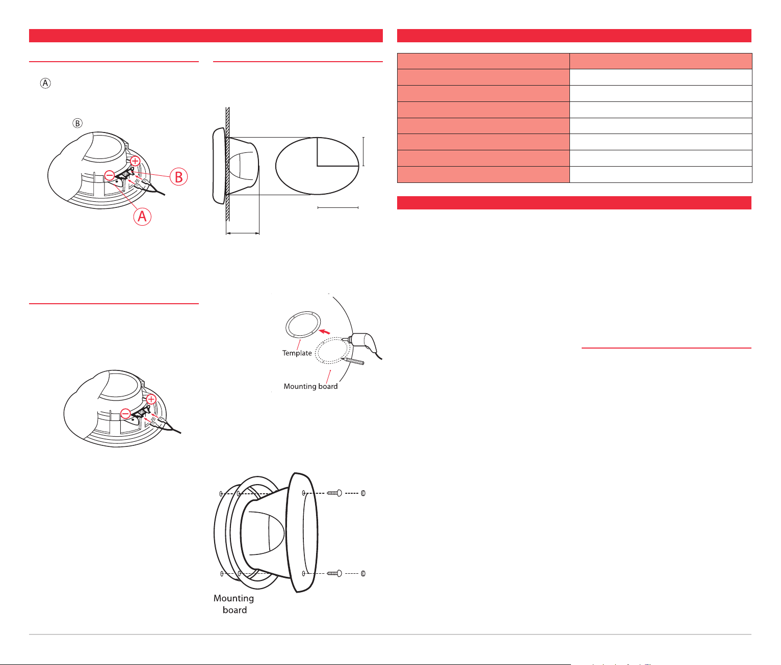
CONNECTING
1. Attach the speaker wires (supplied) to the
speaker terminals be sure to connect the
correct spade connector to the correct size
terminal.
To Amp
/Stereo
2. Connect the other end of the speaker wires to
your amplifier/stereo ensuring ‘+’ goes to ‘+’
and ‘–’ goes to ‘–’.
MOUNTING
1. When mounting the SPK007 in the kick panel,
make sure there is a clearance of 90 mm (3.5”)
behind the well.
76.5
mm
(3”)
111.5 mm
(4.4”)
86 mm
(3.4”)
2. Push out the template from this leaflet and use
to mark the position of the mounting screws
and the outline of the speaker hole.
Drill the mounting
holes and cut
the hole for
the speaker.
3. Place gasket around hole. Place speaker in hole
and using screws supplied screw speaker into
place.
4. Cover screws with cover plugs supplied.
System Coaxial speaker
Power (Watts) 170
Tweeter - mm (inches) 13.28 mm (½) Neo PEI Dome
Efficiency (1W/1 M) 90 db
Frequency Response 60 Hz–22 kHz
Impedance (Ohms) 4
Weight - kgs (lbs) 1.69 (3.73)
WARRANTY
GME limit this warranty to the original purchaser of
the equipment.
GME warrant the SPK007 to be free from defects in
material and workmanship for a period of thirty six
(36) months from the date of purchase from their
authorised retailer.
Should the product require servicing during this
period, all labour and parts used to effect repairs will
be supplied free of charge. GME reserve the right to
determine whether damage has been occasioned by
accident, misuse or improper installation whereby the
warranty would be void, including equipment which
has been damaged due to:
(a) Incorrect or reverse polarity connection to
a battery or power supply or to an incorrect
supply voltage.
(b) Operation without an antenna or by connection
to an antenna which has been incorrectly
installed, resulting in damage to the speaker’s
output circuit.
SPK007
Procedure to be followed by claimant: In the
event of a defect occurring during the warranty
period, the original purchaser may return the
defective unit along with suitable proof of purchase
date (i.e. receipt, docket, credit card slip etc.) and
a full description of the defect to the retailer from
whom the unit was purchased. All freight charges
incurred for transportation by the retailer or GME are
the purchaser’s responsibility.
GME AFTER SALES SERVICE
Your speaker is especially designed for the
environment encountered in land and marine
installations. The use of all solid state circuitry, careful
design and rigorous testing, result in high reliability.
Should failure occur however, GME maintain a fully
equipped service facility and spare parts stock to
meet the customer’s requirements long after expiry of
the warranty period.
(c) Effects of water or moisture penetration.
(d) Non-factory modifications.
SPK007 TECHNICAL SPECIFICATION AND CUTTING TEMPLATE
Page 3

Tear off here
)
t
u
o
h
s
u
P
(
e
l
l
i
r
g
r
e
k
a
e
p
s
f
o
e
g
d
e
r
e
t
u
O
e
p
S
e
l
o
h
r
e
k
a
)
t
u
o
h
s
u
P
(
Mounting Template for SPK007
Please push out.
SPK007 TECHNICAL SPECIFICATION AND CUTTING TEMPLATE
Page 4

SPK007 Cutting Template
SPK007 TECHNICAL SPECIFICATION AND CUTTING TEMPLATE
 Loading...