

Page 1

SPK001
SPK002
MARINE STEREO 2 WAY
COAXIAL SPEAKERS
TECHNICAL SPECIFICATIONS & CUTTING TEMPLATE
Page 2
MOUNTING INSTRUCTIONS
To Amp
/Stereo
PRECAUTIONS
1 Please avoid contact with inside speaker wire
2 Do not change the polarity of the speaker terminal assembly
3 Make sure lead and speaker terminals do not contact metal.
4 When making connections, please refer to the instruction manual
of marine stereo used.
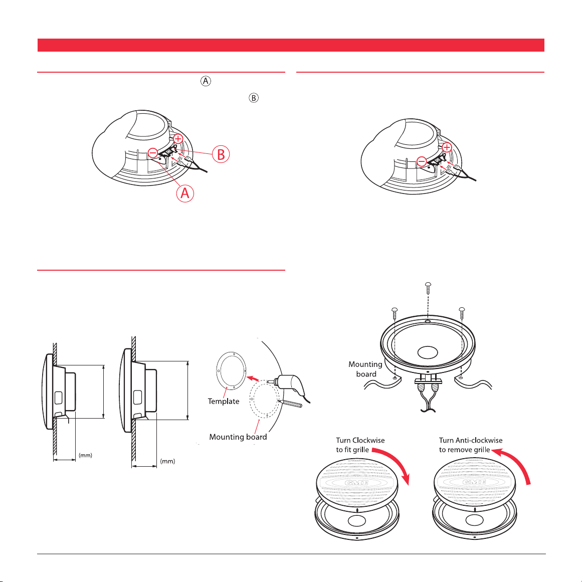
MOUNTING
1. When mounting the SPK001 in the kick panel, make sure there
is a clearance of 55 mm (2.17”) behind the well.
When mounting the SPK002 in the kick panel, make sure there
is a clearance of 65 mm (2.56”) behind the well.
SPK001 SPK002
CONNECTING
1. Attach the speaker wires (supplied) to the speaker terminals be sure to
connect the striped wire to the negative (–) terminal, and the other wire
to the positive (+) terminal of the speaker.
Connect the other end of the speaker wires to your amplifier/stereo.
2. Remove the speaker grille (turn anti-clockwise). Fit the speaker into the
cutout and secure the speaker using the screws (supplied).
Replace the speaker grille on the speaker (turn clockwise) until the grille
locks into place.
145
(5.7”)
55
(2.17”)
(4.8”)
123
65
(2.56”)
2. Push out the template from this leaflet and use to mark the position
of the mounting screws and the outline of the speaker hole. Drill the
mounting holes and cut the hole for the speaker.
PAGE 2 TECHNICAL SPECIFICATION AND CUTTING TEMPLATE SPK001/SPK002
Page 3
)
t
u
o
h
s
u
P
(
e
l
il
r
g
r
e
k
a
e
p
s
f
o
e
g
d
e
r
e
t
u
O
l
o
h
r
e
k
a
e
p
S
)
t
u
o
h
s
u
P
(
e
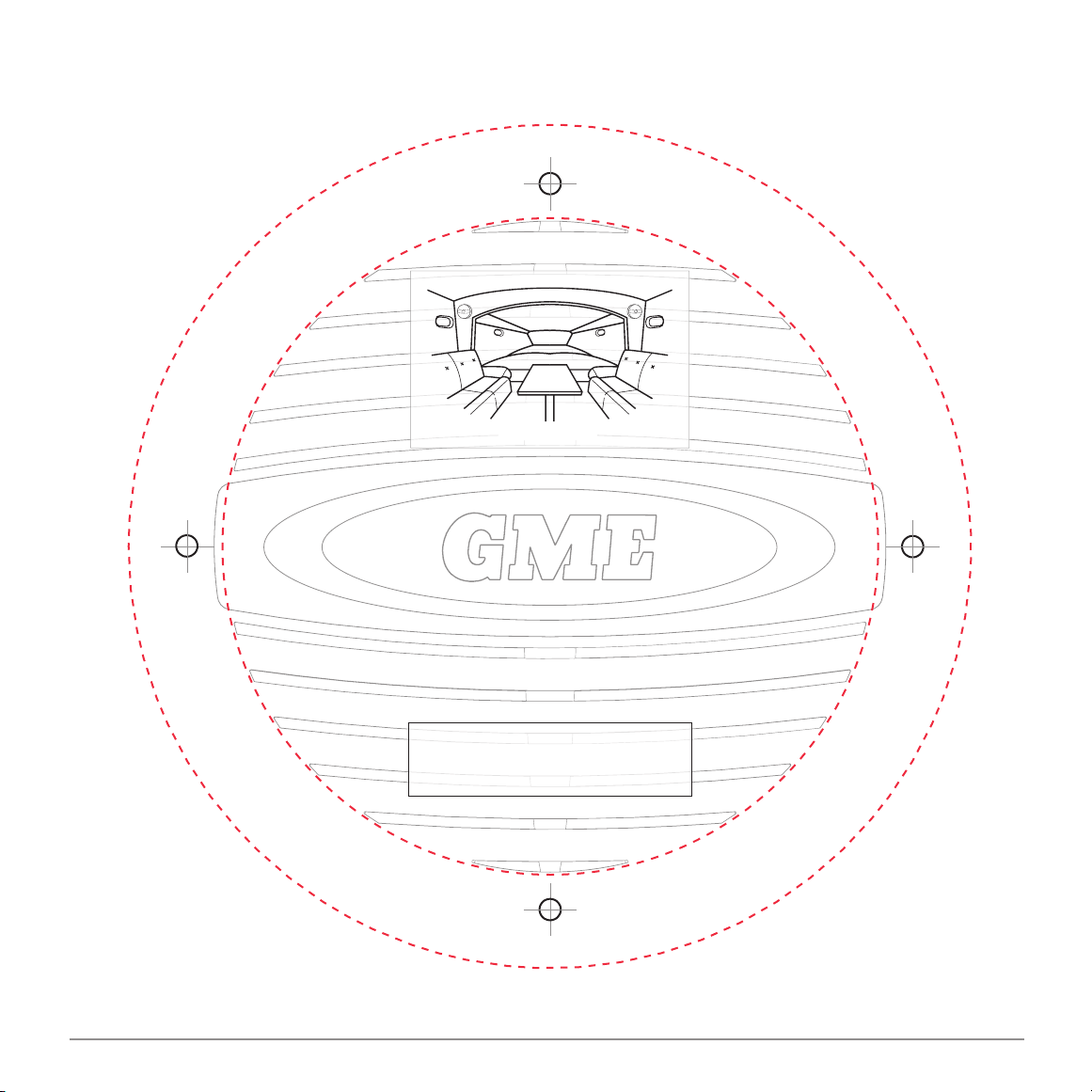
Mounting Example
Mounting Template for SPK001
Please push out.
SPK001 TEMPLATE
SPK001/SPK002 TECHNICAL SPECIFICATION AND CUTTING TEMPLATE PAGE 3
Page 4

SPK001 Cutting Template
PAGE 4 TECHNICAL SPECIFICATION AND CUTTING TEMPLATE SPK001/SPK002
Page 5

)
t
u
o
h
s
u
P
(
e
l
il
r
g
r
e
k
a
e
p
s
f
o
e
g
d
e
r
e
t
u
O
e
l
o
h
r
e
k
a
e
p
S
)
t
u
o
h
s
u
P
(
Mounting Example
Mounting Template for SPK002
Please push out.
SPK002 TEMPLATE
SPK001/SPK002 TECHNICAL SPECIFICATION AND CUTTING TEMPLATE PAGE 5
Page 6

SPK002 Cutting Template
PAGE 6 TECHNICAL SPECIFICATION AND CUTTING TEMPLATE SPK001/SPK002
Page 7

SPEAKER DRIVER SPECIFICATIONS
SPK001 SPK002
System Coaxial woofer/tweeter Coaxial woofer/tweeter
Power (Watts) 110 140
Tweeter Neo PEI Dome Neo PEI Dome
Efficiency (1W/1M) 88 db 89 db
Frequency Response 80 Hz–20 kHz 70 Hz–20 kHz
Impedance (Ohms) 4 4
Weight - kgs, (lbs) 0.78 (1.72) 1.34 (2.95)
Speaker Depth - mm (inches) 55 (2.17) 65 (2.56)
WARRANTY
GME limit this warranty to the original purchaser of the equipment.
GME warrant the SPK001/SPK002 to be free from defects in material
and workmanship for a period of thirty six (36) months from the date of
purchase from their authorised retailer.
Should the product require servicing during this period, all labour and parts
used to effect repairs will be supplied free of charge. GME reserve the right
to determine whether damage has been occasioned by accident, misuse
or improper installation whereby the warranty would be void, including
equipment which has been damaged due to:
(a) Incorrect or reverse polarity connection to a battery or power supply
or to an incorrect supply voltage.
(b) Operation without an antenna or by connection to an antenna which
has been incorrectly installed, resulting in damage to the speaker’s
output circuit.
Procedure to be followed by claimant: In the event of a defect
occurring during the warranty period, the original purchaser may return
the defective unit along with suitable proof of purchase date (i.e. receipt,
docket, credit card slip etc.) and a full description of the defect to the
retailer from whom the unit was purchased. All freight charges incurred for
transportation by the retailer or GME are the purchaser’s responsibility.
GME AFTER SALES SERVICE
Your speaker is especially designed for the environment encountered in
land and marine installations. The use of all solid state circuitry, careful
design and rigorous testing, result in high reliability. Should failure occur
however, GME maintain a fully equipped service facility and spare parts
stock to meet the customer’s requirements long after expiry of the
warranty period.
(c) Effects of water or moisture penetration.
(d) Non-factory modifications.
SPK001/SPK002 TECHNICAL SPECIFICATION AND CUTTING TEMPLATE PAGE 7
Page 8

Part Number: 310439 Drawing Number: 44307-3
T ECHNICAL SPECIFICATIO N AND CUTT ING TEMP LAT E S PK001/S PK002
 Loading...