

GME RC900 User Manual

CD/MP3 Player AM/FM Radio
INSTRUCTION MANUAL

GME STRONGLY RECOMMENDS THAT YOU KEEP THIS MANUAL
IN A SAFE PLACE FOR FUTURE REFERENCE
CONTENTS
FEATURES
ACCESSORIES SUPPLIED
INTRODUCTION
CONTROL LOCATIONS
INSTALLATION
Precautions ..........................4
Handling Compact Discs .................4
Moisture /Condensation .................4
Location .............................4
Installing the RC900 into a DIN sized recess ..4
Electrical Wiring .......................5
Fuse Replacement ......................6
OPERATION
General Functions ......................6
...............................2
....................2
..........................3
. . . . . . . . . . . . . . . . . . . . . . 3
...........................4
.............................6
Radio Operation .......................7
CD/MP3 Operation .....................8
MP3 MUSIC SEARCH ...................9
CONFIGURATION MENU TABLE
AUXILIARY INPUTS & OUTPUTS
Front Panel Inputs .....................10
Connecting an iPod*. . . . . . . . . . . . . . . . . . . 10
Rear Output .........................10
OPTIONAL ACCESSORIES
RC900 TROUBLE SHOOTING GUIDE
SPECIFICATIONS
STANDARD C OMMUNICATIONS
CONTRACT WARRANTY AGAINST DEFECTS
FLUSH MOUNT CUTTING TEMPLATE
.........................13
...............9
..............10
...................11
...........12
.....14
..........15
FEATURES
MP3 via CD/USB/SD card and auxiliary input
•
4 x 45 watt power output
•
Backlit LCD screen
•
iPod* connectivity via optional
•
interconnect cable
*iPod is a trademark of Apple Computer Inc., registered in the US and
other countries.
PAGE 2 INSTRUCTION MANUAL RC900 SERIES
ACCESSORIES SUPPLIED
The RC900 is supplied with the following
standard accessories:
Main unit
•
Remote control
•
DC/speaker cable harness
•
Din mounting kit
•
Instruction manual
•
Please immediately contact your point of purchase
if any of these components are missing
.
INTRODUCTION
Congratulations on your purchase of the GME RC900
CD/MP3 Player/ AM FM Radio, arguably the finest audio
product available today. Your RC900 has been designed
with the music buff in mind. By way of a host of features
never before found in a in vehicle stereo system, the RC900
offers music enthusiasts the same level of audio quality
normally reserved for high end home systems.
The RC900 series has been developed utilising the very
latest in digital electronic technology combined with the
design expertise gained by GME engineers over several
decades of product development. The RC900 has all
the attributes expected from a superior stereo system,
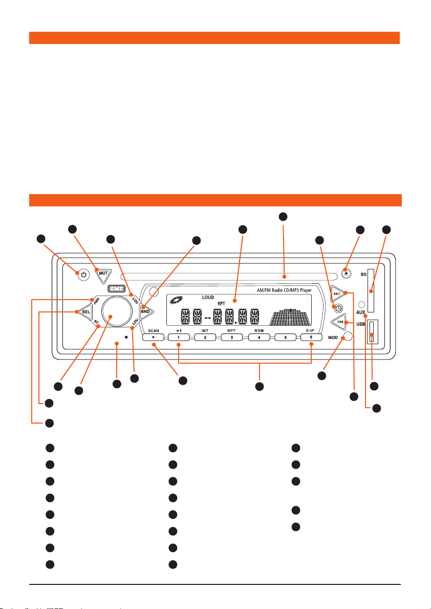
CONTROL LOCATIONS
1
5
8
10
RC900
RESET
furthermore, inclusions of SD and USB inputs and iPod®
compatibility, will ensure the RC900 is destined to become
the standard by which all in vehicle stereo systems are
measured.
Please read this instruction booklet carefully, drop in your
favourite music selection, sit back and enjoy the
sounds that cannot fail to impress even the most
critical audiophile.
16
15
6
4x45
Watts
D-DN
20
12
7
11
17
Auxiliary Input
18
USB Input
19
Preset memory Keys and
CD/MP3 functions.
20
SD Card Input
21
Reset Button
18
17
9
2
3
13
1
Power On/Off
2
Volume Control
3
Select
4
Loudness
5
Mute
6
Clock/Time Selector
7
Mode Switch
8
LOC/DX Selector
4
21
14
9
Stereo/Mono
10
Band Selector
11
Tuning/Selecting Tracks
12
Eject
13
Auto Music Search
14
Scan
15
LCD Display
16
CD Slot
19
RC900 SERIES INSTRUCTION MANUAL PAGE 3
INSTALLATION
PRECAUTIONS
If you are connecting your RC900 for the first time or
have just reconnected your vehicle battery and you are
experiencing problems with the unit’s operation, we
suggest you try resetting the unit. The reset button is
located on the front panel below the volume control. Gently
press the reset button with a paper clip or similar object.
The preset station memories and clock time are retained
only while the yellow ‘Memory’ lead is connected to a
continuous + 12 V DC supply (see Electrical Wiring section).
If the battery is disconnected or switched off at the master
switch, or the unit is removed from the vehicle, the station
memories will be lost and the clock will need to be reset.
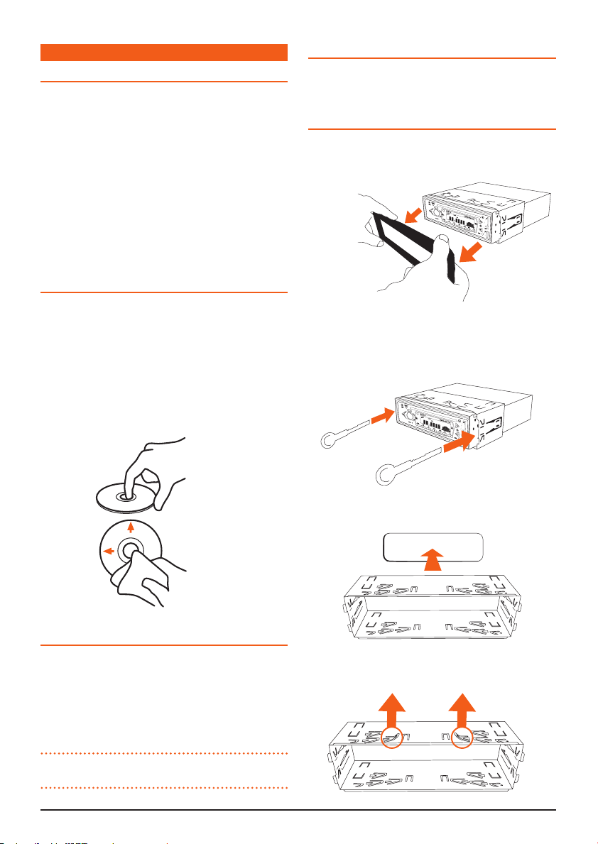
HANDLING COMPACT DISCS
Handle the CD by it’s edge, avoid touching the
•
disc surface.
Store your CDs away from direct sunlight or heat
•
sources. Keeping the CD in it’s original case will help to
keepit flat.
Clean the CD with a soft cloth from the centre to the
•
outer edge, (see diagram) rather than in a ci lar
motion. Do not use solvents.
LOCATION
GME recommends that the unit should be mounted in a
position that is free from direct sunlight and
excessive vibration.
INSTALLING RC900 INTO A DIN SIZED RECESS
The RC900 is designed to be installed with the mounting
accessories provided.
1. Remove the front panel surround.
2. Insert release keys between the RC900
and the DIN sized mounting frame, so that the locking
tabs on the mount frame are released. Remove the
RC900 from the mounting frame.
3. Insert the mounting frame into the DIN sized recess.
MOISTURE /CONDENSATION
Your RC900 uses optical laser technology. Occasionally
damp or humid conditions may cause condensation to
appear on the lenses inside the unit. Should this occur, the
unit might not operate correctly. Simply eject the CD and
leave the unit turned on for a while until the
moisture evaporates.
NOTE: The RC900 should not be mounted at angles
greater than 30° above or below the horizontal.
PAGE 4 INSTRUCTION MANUAL RC900 SERIES
4. Bend the tabs to secure the frame in the recess.
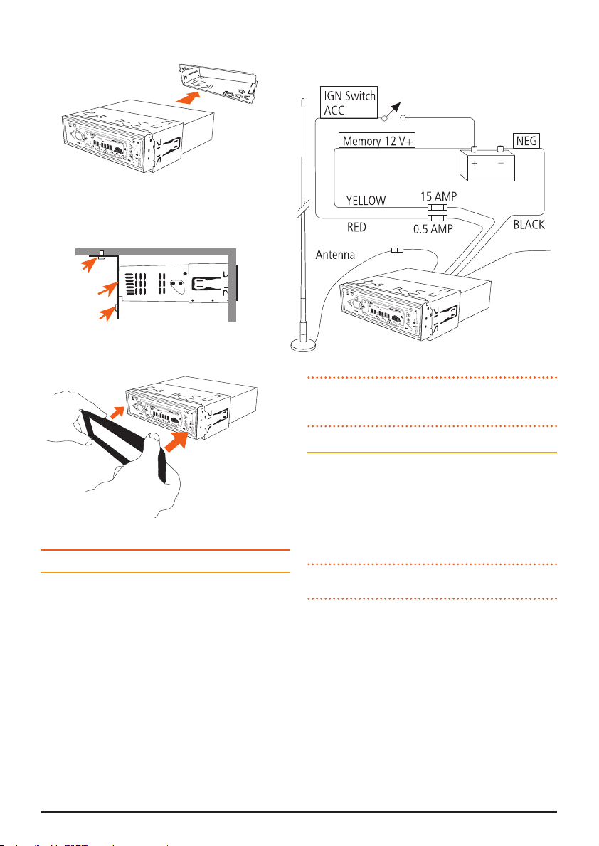
6. Insert the RC900 in the Mounting Frame.
7. Attach the support strap provided to the rear of the
RC900 and fastened strap to dash framework or
added support.
Screw
Strap
Screw
8. Reattach the front panel surround.
ELECTRICAL WIRING
DC Connections
Caution:
The RC900 is designed for vehicles with a 12 volt
negative ground electrical system only!
Referring to the wiring diagram on this page:
1. Connect the YELLOW wire directly to the positive
terminal of the vehicle’s battery, or to a point that has
+12 Volts available at all times. This lead maintains
the memories within the RC900 and is the main power
source for the unit.
2. Connect the RED wire to the vehicle’s +12 V supply
via an appropriate isolating switch or circuit breaker.
This lead enables the radio to be switched ON and OFF.
Alternatively, this wire can be connected directly to the
battery’s positive terminal and the RC900 switched ON
and OFF using it’s own controls.
3.
Connect the BLACK wire to the battery’s negative
or to the common negative bus in the electrical system.
NOTE: The blue wire on the wiring loom supplies 12 volts
when the RC900 is switched on and can be used to turn on
an external device, like the GME GA9800 amplifier.
Speaker Connections
When connecting the speakers, observe the correct polarity as
shown in the diagram above right. Incorrect polarity will result in a
reduction of bass response and stereo effect. The use of speakers
with an impedance of less that 4 Ohms is not recommended, as
they will cause excessive loading of the RC900’s output circuit
and may result in the radio overheating.
CAUTION: The RC900 is a four-speaker system that
requires 2 separate wires for each speaker.
A range of GME speakers is available from your local
GME retailer.
Connect all four speakers as shown in the diagram above.
Adjust the Fader control for the required front/rear balance.
terminal
BLUE
AUTO ANTENNA
12 V+ OUT
RC900 SERIES INSTRUCTION MANUAL PAGE 5
 Loading...