

Page 1
Hepworth Heating Ltd.,
Nottingham Road, Belper, Derbyshire. DE56 1JT
General/Sales enquiries:
Tel: (01773) 824141 Fax: (01773) 820569
One Contact Local Service
Customer Services:
Tel: (01773) 828100
Fax: (01773) 828070
This is a Cat I2H Appliance
8023
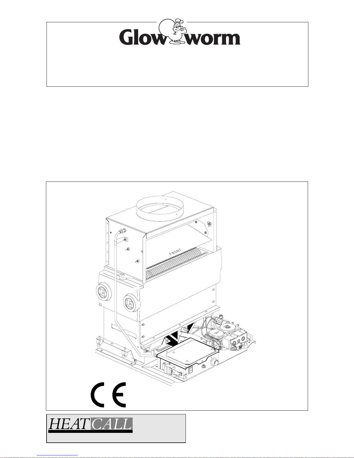
INSET BBU 50
Installation & Servicing Instructions
221723B.10.00
To be left with the user
G.C. No. 44 047 02
For Use Only With Specially Designed Fire Fronts
Page 2

2
221723B
General Data 1 3
Types of Installation 2 6
Flue and Ventilation 3 7
Installation 4 8
Electrical Wiring 5 13
Commissioning 6 16
Fire Installation 7 18
Servicing 8 18
Fault Finding 9 22
Replacement Parts 10 24
Spare Parts 11 28
CONTENTS DESCRIPTION SECTION PAGE No.
INSTALLATION
INSTRUCTIONS
SERVICING
INSTRUCTIONS
B.S.I Certification
It is important that no alteration is made to the boiler without permission, in writing, from Hepworth Heating Ltd.
Any alteration that is not approved by Hepworth Heating Ltd., could invalidate the B.S.I. Certification, the boiler warranty and could
also infringe the current issue of the Statutory Requirements, see Section 1.1.
CE Mark
The boiler meets the requirements of Statutory Instrument, No. 3083 The Boiler (Efficiency) Regulations, and therefore is deemed
to meet the requirements of Directive 92/42 EEC on the efficiency requirements for new hot water boilers fired with liquid or gaseous
fuels.
Type test for purposes for Regulation 5 certified by: Notified body 0086.
Product/production certified by: Notified by 0086.
1. Directive 90/396/EEC on the approximation of the Laws of the Member States relating to appliances burning gaseous fuels.
2. Directive 73/23/EEC on the harmonization of the Laws of the Member States relating to electrical equipment designed for use
within certain voltage limits.
3. Directive 89/336/EEC on the approximation of the Laws of the Member States relating to electromagnetic compatibility.
INFORMATION FOR THE INSTALLER AND SERVICE ENGINEER.
Under Section 6 of The Health and Safety at Work Act 1974, we are required to provide information on substances hazardous to
health.
The adhesives and sealants used in this appliance are cured and give no known hazard in this state.
RADIANTS, FUELBEDS, ARTIFICIAL FUEL
After handling wash hands thoroughly.
INSULATION PADS/CERAMIC FIBRE, GLASSYARN, MINERAL WOOL
These can cause irritation to skin, eyes and the respiratory tract.
If you have a history of skin complaint you may be susceptible to irritation. High dust levels are usual only if the material is broken.
Normal handling should not cause discomfort, but follow normal good hygiene and wash your hands before eating, drinking or going
to the lavatory.
If you do suffer irritation to the eyes or severe irritation to the skin seek medical attention.
THERMOSTATS
These contain very small amounts of trichlorofluoromethane in the sealed phial and capillary. If broken, under normal circumstances
the fluid does not cause a problem, but it can, in exceptional cases cause freeze burns.
If there is skin burn or irritation to the eyes or skin seek medical attention.
These contain very small amounts of xylene in the sealed phial and capillary. If broken, under normal circumstances the fluid does
not cause a problem, but in cases of skin contact, wash with cold water.
If swallowed drink plenty of water and seek medical attention.
CUT-OFF DEVICES
These contain a very small amount of ethylene glycol and methanol in the capillary. If broken, under normal circumstances the fluid
does not cause a problem, but in cases of skin or eye contact, wash with cold water.
If swallowed drink plenty of water and seek medical attention.
Important Information
Page 3

3 221723B
1 General
References in these instructions to British Standards, Statutory
Regulations and Requirements apply only to the United Kingdom.
For Ireland the rules in force must be used.
The instructions consist of three parts, Installation and Servicing
Instructions for the Back Boiler Unit, Installation and Servicing
Instructions for the specified Fire Front and Instructions for Use
and the Guarantee Registration Card. The instructions are an
integral part of the appliance and must, to comply with the
current issue of The Gas Safety (Installation and Use)
Regulations, be handed to the user on completion of the
installation.
The Glow-worm Inset 50 Back Boiler Unit, GC No. 44 047 02 is
for use only with the Glow-worm Inset Fire Fronts.
1 General Notes and Information
IMPORTANT NOTICE
This boiler is for use only on G20 gas.
The back boiler unit is fitted with a flue blockage safety device
which will shut it down if there is a lack of oxygen resulting from
a build up of combustion products, the flame on the pilot light will
become unstable and lift up off the thermocouple. This will
deactivate the mag unit in the gas control valve, cutting off the
gas supply.
If the back boiler unit shuts down frequently for no apparent
reason the first things to check are the chimney and air inlets
into the room. Any problems found must be put right, by a
competent person, and a full operational test carried out before
the fire is used again.
The flue blockage safety device incorporates the electrode,
thermocouple and pilot assemblies.
The flue blockage safety device MUST NOT be adjusted or
disconnected. It must be serviced strictly in accordance
with the instructions in this book. Any unauthorised
interference could result in the device failing to operate,
creating a potentially dangerous situation. If replacing, use
only the correct and approved parts.
Wherever possible, all materials, appliances and components
to be used shall comply with the requirements of applicable
British Standards.
Where no British Standard exists, materials and equipment
should be fit for their purpose and of suitable quality and
workmanship.
This boiler, together with its fire can be used on a precast flue,
see Section 3.4.
Sheet Metal Parts
WARNING. When installing or servicing this back boiler care
should be taken when handling the edges of sheet metal parts
to avoid any possibility of personal injury.
1 General
1.1 Statutory Requirements
The installation of this back boiler unit must be carried out by a
competent person in accordance with the current issue and
relevant requirements of:
Manufacturer’s instructions, supplied.
The Gas Safety (Installation and Use) Regulations, The Building
Regulations, The Building Standards (Scotland) Regulations,
applicable in Scotland, Local Gas Undertaking, Bye-laws of the
Local Water Company, The Health and Safety at Work Act,
Control of Substances Hazardous to Health, The Electricity at
Work Regulations and any applicable local regulations.
Detailed recommendations are contained in the current issue of
the following British Standard codes of practice,
BS1251, BS5440 Part 1 and 2, BS5449, BS5546, BS5871,
BS6798, BS6891, BS7593, BS7671.
Manufacturer’s notes must not be taken as overriding statutory
obligations.
1.2 Data BBU 50
Gas connection Rc1/
2
(1/2inBSPT)
Water connection Supplied in fittings pack
Electrical supply 230V~50Hz fused 3A
Weight, about 40kg
(81.6lb)
Water content 3.11Litres
(0.68gall)
Injector 3.5mm
Dimensions, except as noted, shown on diagrams are in
millimetres.
Data Label: On the base of the boiler next to the electrical
control box.
The Seasonal Efficiency Domestic Boilers UK (SEDBUK)
is 76.8%.
The value is used in the UK Government’s Standard Assessment
Procedure (SAP) for energy rating of dwellings. The test data
from which it has been calculated have been certified by B.S.I.
1.3 Gas Supply
The gas installation must be in accordance with the current
issue of BS6891.
The supply from the governed gas meter must be of adequate
size to provide a steady inlet working pressure of 20mbar (8in
wg) at the boiler.
On completion test the gas installation for soundness using the
pressure drop method and suitable leak detection fluid, purge
in accordance with the above standard.
1.4 Electrical Supply
WARNING. This boiler must be earthed.
All system components shall be of an approved type and shall
be connected in accordance with the current issue of BS7671
and any applicable local regulations.
Connection of the boiler and system controls to the mains
supply should be through a common isolator , a double pole
isolating switch, fused 3A, should be used, having a minimum
contact separation of 3mm in both poles.
Alternatively, a fused 3A 3pin plug and unswitched shuttered
socket both to the current issue of BS1363 may be used.
Wiring to the boiler must be PVC (85
o
C) insulated type to the
current issue of BS6500 Table 9, not less than 0.75mm
2
(24/
0.20mm).
Page 4
4
221723B
1 General
C
L of Flue
C
L
FLUE
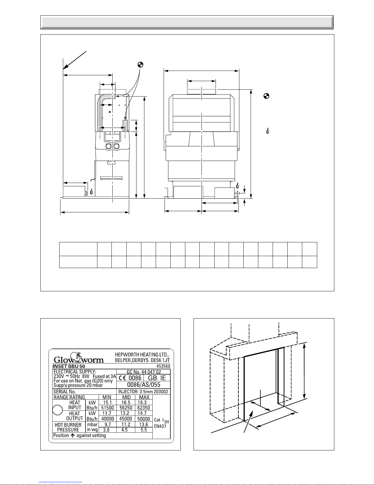
OVERALL DIMENSIONS
(RIGHT HAND WATER CONNECTION SHOWN)
6173
Diagram 1.1
DIMENSION A B C D E F G H J K L M N P R
50 / BBU 550 400 337 245 130 164 146 193 174 39 348 65 530 80 50
D
A
B
C
E
F
G
H
J
K
WATER
CONNECTIONS
22mm COPPER PIPE
GAS CONNECTION
RC (1/2 in BSPT)
SIDE ELEVATION
FRONT ELEVATION
H
L
M
FIRE FIXING WALL FACE
N
P
R
TABLE 1
INSET BBU 50
RANGE RATING
Diagram 1.2
6302
405mm MIN
500mm MAX
560mm MIN
590mm MAX
PREPARED
BASE
350mm
MIN
Page 5
5 221723B
Diagram 1.4
Diagram 1.5
6242
6243
BOILER
22mm
CENTRAL
HEATING
RETURN
28mm
DISTRIBUTOR
TUBE IN RETURN
CONNECTION
22mm
CENTRAL
HEATING
FLOW
FLOW
RETURN
INDIRECT
CYLINDER
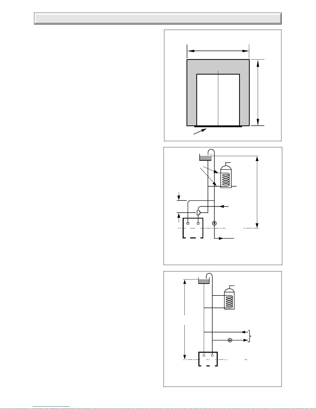
27 METRES
MAXIMUM
FIXED
DIMENSION
C
L
INDIRECT
CYLINDER
PUMP
TO HEATING
CIRCUIT
1 METRE MIN
27 METRE MAX
RETURN
FLOW
BOILER
C
L
PUMPED HEATING & GRAVITY DOMESTIC HOT
WATER (DIAGRAMMATIC)
FULLY PUMPED SYSTEM
(DIAGRAMMATIC)
1.5 Contents of Packaging
The boiler is delivered in one pack which contains all the parts
required for installation.
1.6 Site Requirements
For all types of installation a standard 16inch builder’s opening
is required, see diagram 1.2.
Note: The depth of the fire opening is IMPORTANT, it MUST
therefore conform to the dimensions given in diagram 1.2.
Any larger opening will need to be reduced, with non-combustible
material to conform to this requirement.
It is important that the opening is cleared of debris and mortar
etc.
The prepared base for the back boiler must be level.
Refer to diagram 1.3 for dimensions of the fire fixing wall face
which MUST be true.
1.7 Water System - Open Vented
This boiler can be used on an unrestricted open vented system
with the water supply taken from a feed and expansion cistern,
having a head between 1m (3ft 3in) minimum and 27m (90ft)
maximum.
Diagrammatic layouts of systems are shown in diagram 1.4 and
1.5.
Sealed Water System
A Kit and instructions, Part No. 459033, is available to enable
the back boiler to be used on a sealed water system.
Please give the serial number of the back boiler unit when
ordering the kit.
1.8 Hot Water Cylinder
The back boiler is suitable for open vented systems using an
indirect cylinder (including single feed self priming type). The
cylinder must be fitted to the manufacturer’s recommendations
and the system must conform to the requirements of the current
issue of BS5449.
It is recommended that the cylinder be fitted with some form of
temperature control.
1.9 Frost Protection
If the position of the boiler is such that it may be vulnerable to
freezing it should be protected as specified in the current issue
of BS5422.
It is also recommended that a frost thermostat is fitted.
1.10 Draining Tap
A draining tap must be provided at the lowest point of the system
which will allow the entire system, the boiler and hot water
cylinder to be drained.
Draining taps shall be to the current issue of BS2879.
1.11 Safety Valve
A safety valve need not be fitted to an open vented system.
1.12 Boiler Location
This back boiler unit MUST NOT be installed in a private garage
or in a room containing a bath or shower or a room used or
intended to be used as sleeping accommodation.
1 General
Diagram 1.3
C
L
5506
690
Minimum flat area and fixture or
surround protection clearance
PREPARED BASE
800 MIN WIDE FRAME
780 MIN STANDARD FRAME
Page 6
6
221723B
Diagram 2.1
Diagram 2.2
2 Types of Installation
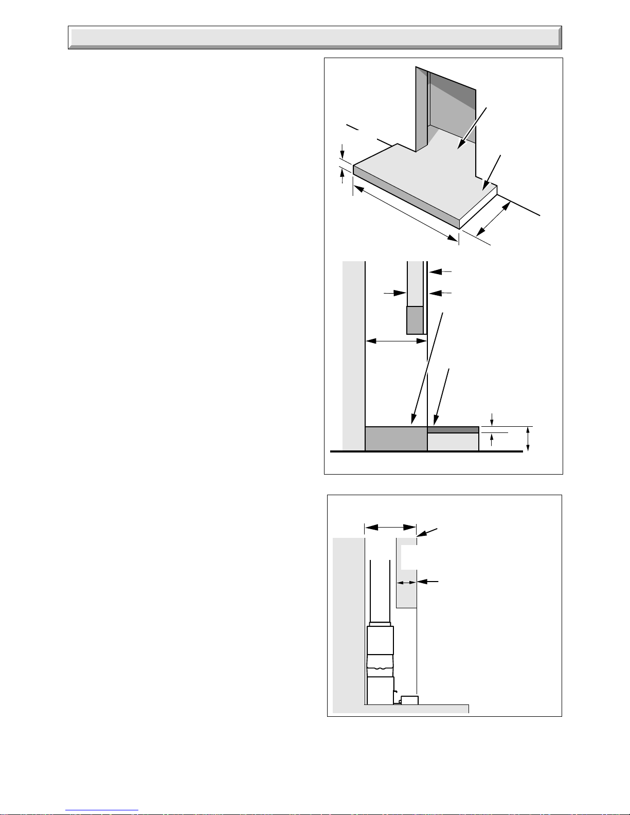
2.1 Hearth
In ALL cases there MUST be a non-combustible hearth under
the fire front.
For minimum dimensions of a hearth see diagram 2.1.
Carpet or similar floor covering must not be placed on the
hearth.
If the boiler is to be mounted above the prepared hearth the
hearth must still conform to the instructions above and the
dimensions given in diagram 2.1.
2.2 Fire Surround
The combined thickness of the surround and the lintel must be
checked, to ensure that the back boiler can be positioned within
the opening to allow easy connection of the flue into the boiler
flue socket, see diagram 2.2.
For fireplaces where the wall is not plastered and not covered
by BS1251 it is important that such installations comply with the
current issue of The Building Regulations.
Any combustible material, for example, blown vinyl wall coverings,
on the fire fixing face area of the surround must be removed, see
diagram 1.3.
2.3 Without Fire Surround
The builder’s opening, with lintel must have minimum dimensions
as shown in diagrams 1.2 and 2.2.
5423
6196
PREPARED
BOILER
BASE
HEARTH
300mm
650mm
50mm MIN
FIRE WALL FACE
165mm
MAX
PREPARED BASE
TOPS OF HEARTH
MUST NOT BE
ABOVE PREPARED
BASE
13mm MIN
NON-COMBUSTIBLE
MATERIAL
50mm
MIN
350mm MIN
FIRE FIXING
WALL FACE
*NOTE
This dimension can
be increased up to
190mm if builder’s
opening depth is at
least 375mm deep
*165mm
MAX
FLUE
PIPE
350mm
MIN
Page 7
7 221723B
Diagram 3.2
BACK
BOILER
UNIT
6197
SEALING AND
CLAMPING
PLATE
AIR
SPACE
150mm (6in) plug of Mineral Wool or similar
600mm
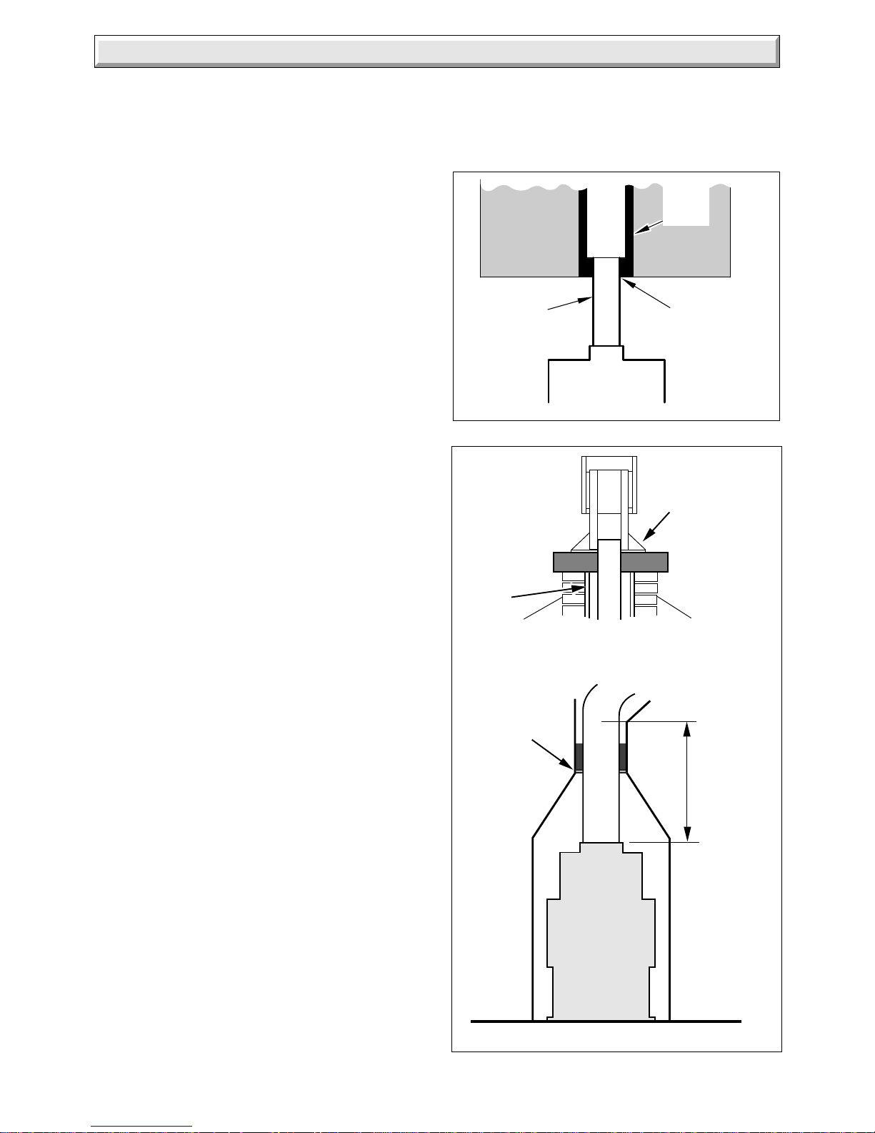
3 Flue and Ventilation
Diagram 3.1
3.1 General
The general recommendations of the current issue of BS5440
Part 1 should be followed.
In all cases the flue should be lined, preferably with a flexible
liner.
It is essential that the flue has an equivalent height of at least
2.5m (8.2ft) measured from the flue connection on the appliance.
The first 600mm, at least, above the draught diverter must be
vertical.
Where the installation is new it is essential to make sure that the
annular space between the boiler flue liner and the chimney is
sealed at the base and at the top of the chimney, as shown in
diagram 3.2.
The flue socket is designed to take flue pipe to BS567. If flue
pipe conforming to a different standard is used a suitable
adapter must be fitted and secured to the flue socket. A flexible
flue liner may be used, with connection to the back boiler flue
socket, see diagram 3.1.
The existing flue may not be completely sound. Therefore, to
prevent the possibility of leakage to an adjacent flue, additional
sealing MUST be carried out between the base of the chimney
and the flue liner.
The end of the flue liner at the chimney top must be adequately
sealed and clamped, using proprietary fittings suitable for the
flue liner used, see diagram 3.2.
The flue should, preferably, end above ridge height but at the
least above the eaves of a pitched roof. Use a certificated
terminal.
If the flue is to pass through or near any combustible material it
should be installed in accordance with the current issue of
BS5440 Part 1. If in doubt seek advice from the local gas
undertaking or Hepworth Heating Ltd.
3.2 Existing Chimney
An existing brick chimney must be thoroughly swept and all
debris cleared away before lining.
Remove any damper or register plate. Alternatively it may be
locked in the open position,
A flexible flue liner is preferred but a rigid liner may be used, with
connection to the back boiler flue socket made with a short
vertical piece of flexible liner, see diagram 3.1.
Any air supply that enters the builder’s opening other than by the
front opening, that is underdraught openings and the like must
be completely sealed off.
The sealing plate also prevents debris falling and gives the flue
better insulation, reducing the possibility of condensation, see
diagram 3.2.
Check the flue system efficiency before installing the back
boiler.
3.3 New Chimney
A newly built chimney can be lined with a moisture resistant
lining, such as salt glazed pipe, of an appropriate diameter as
specified in the Building Regulations
In the case of a salt glazed lined flue, it is recommended that a
short vertical length of flue pipe, preferably flexible metallic be
used. Fix and seal it to the back boiler flue socket, make good
with approved packing and parge with fire cement, see diagram
3.1.
If a flue and false chimney breast are to be constructed all
openings for pipework to upper floors etc., must be sealed. The
only opening for the back boiler must be at the front, being of the
dimensions as shown in diagram 1.2.
1593
APPROVED
SEAL
FLEXIBLE
LINER
BACK BOILER
RIGID
FLUE
LINER
If a specially built compartment is constructed for the back
boiler, it must conform to the requirements of the current issue
of BS5440 Part 1 and BS5871.
The flue should, preferably, end above ridge height but at least
above the eaves of a pitched roof. Use a certificated terminal.
SEALING
PLATE
Page 8

8
221723B
3 Flue and Ventilation
3.4 Precast Flue
The appliance is suitable for fitting to a properly constructed
non-impeded precast flue.
Note: It is not recommended that this boiler is fitted to a pre-cast
flue where plaster/rendering has been applied directly on to the
face of the flue block as this could lead to high surface temperature
and cracking of the plaster.
There must be a minimum vertical effective height of 3metres.
The flue cross sectional area must not be less than
198mmx97mm.
It is essential that the correct recess blocks, cover block and
offset blocks suitable for back boiler units have been used.
A sealed connection must always be made between the boiler
socket and the precast flue.
Note: It is possible, if this is a replacement, that the previous
appliance may have been more tolerant in respect of flue
requirements.
It is essential, therefore, as for ALL installations to make sure
that there is no spillage of the products of combustion from this
new appliance.
3.5 Ventilation - Back Boiler and Fire
The room in which the back boiler unit is installed must have
adequate air inlets to ensure correct operation as specified in
the current issue of BS5440 Part 2.
Ventilation requirement for the BBU 50 is 84cm
2
(13in2).
This ventilation area takes into account the total requirement of
the back boiler unit and fire.
The ventilation openings may be direct to the outside air or with
an internal room or space (such as a hall) which itself has a
permanent air vent of the same effective area. The permanent
air vent should be in a position which will cause the least
nuisance to occupants, due to draughts.
This vent MUST NOT be placed in the builder’s opening.
If the appliance is to be installed in a room already containing
another fuel burning unit, the air supply required for this other
unit MUST be added to the figure above.
Any air vent taken through a cavity wall must be ducted.
3.6 Extract Fans
If an extract fan is fitted in the premises, there is a possibility that
if adequate air inlet openings are not provided spillage of the
products of combustion could occur.
When openings are fitted in accordance with the
recommendations of the current issue of BS5440 Part 2, extract
fans should not cause spillage.
Where such a fan installation is found, a clearance of products
test must be conducted as described in the fire front Installation
Instructions, Section 4.5.
This test must be carried out with the back boiler fitted with its
fire front.
See also Section 6.3 of these instructions.
Note: Refer again to Section 1.7 and diagram 1.2 and make
sure that there is sufficient depth for the back boiler unit.
4.1 Preparation
Remove draught diverter, flueway baffles and fittings pack from
carton.
Check contents of fittings pack against packed list.
Remove back boiler body assembly from carton.
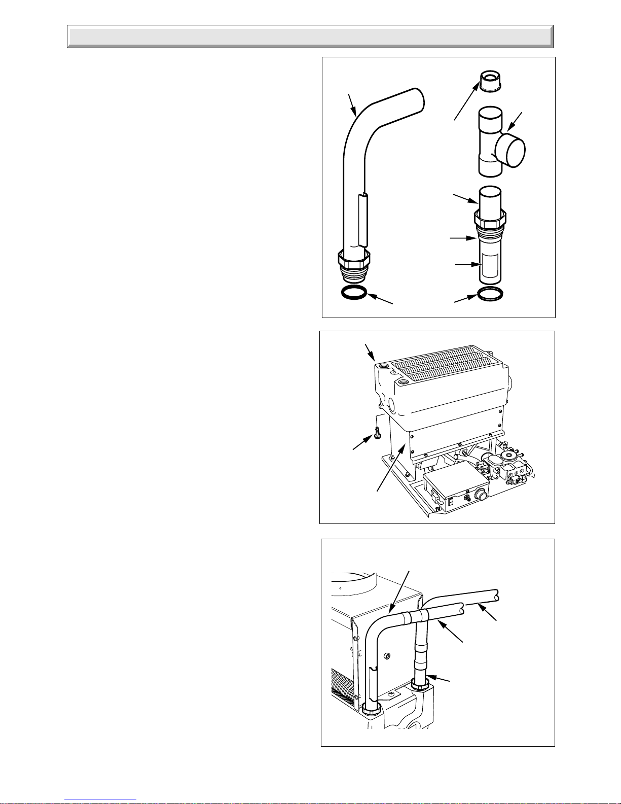
4.2 Water Connections
IT IS EXTREMELY IMPORTANT THAT NO SERVICE PIPES
ARE ROUTED IN FRONT OF THE BOILER. If the builder’s
opening was previously used for solid fuel all pipework within
should be protected with PVC tape or equal. Pipework passing
through walls of the opening should be sleeved and made good.
The two heat exchanger connections are supplied in the fittings
pack and MUST be used, see diagram 4.1.
IMPORTANT: Make sure that the return pipe assembly is
fitted the correct way, that is, the brazed joint must be
positioned downward into the heat exchanger - remove
label before fitting - see diagrams 4.1 and 4.4.
NOTE: Take care when soldering the copper connections not to
damage the fibre washers.
4.3 Pumped Heating with Gravity Domestic
Hot Water
NOTE: The draught diverter and capillaries are shown to aid
plumbing, but would not be fitted at this stage.
All pipework must comply with the current issue of BS5546.
The domestic hot water flow and return pipes must be 28mm.
Refer to diagram 1.4 for a diagrammatic layout.
4 Installation
If it is necessary to route pipework from both sides of the
builder’s opening, it is recommended that the heat exchanger is
positioned on the combustion chamber so that the gravity
circuits exit on the same side as the boiler connections.
If the heat exchanger connections are opposite hand to that
required, the heat exchanger can be turned, as follows, remove
the four screws securing the heat exchanger to combustion
chamber, see diagram 4.2. Turn heat exchanger, refit the four
screws.
It is recommended that pumped heating connections are prepiped as in diagram 4.4.
IMPORTANT: Make sure that the return pipe assembly is
fitted the correct way, that is, the brazed joint must be
positioned downward into the heat exchanger - remove
label before fitting - see diagrams 4.1 and 4.4.
Note: The diagram 4.4 shows two methods “A” and “B” of
plumbing the flow pipe.
The central heating return must have the injector fitted on both
methods “A” and “B”, see diagram 4.4 for fitting the injector.
4.4 Pumped Heating and Hot Water
NOTE: The draught diverter and capillaries are shown to aid
plumbing, but would not be fitted at this stage.
Refer to diagram 1.5 for a diagrammatic layout.
If it is necessary to route pipework from both sides of the
builder’s opening it is recommended that the heat exchanger is
positioned on the combustion chamber such that the flow pipe
exits on the same side as the boiler connections.
It is recommended that the pumped return is pre-piped as in
diagram 4.3.
Page 9
9 221723B
4 Installation
If the heat exchanger connections are opposite hand to that
required, turn in the same manner as described in Section 4.3
paragraph 5.
4.5 Heat Shield Assembly
If the boiler electrical supply cable has to be routed down the left
hand side of the combustion chamber you must fit the heat
shield assembly supplied in the fittings pack. Refer to Section
5.1 and diagrams 5.2 and 5.3.
4.6 Circulating Pump
Isolating valves, integral if possible, must be fitted each side of
the circulating pump.
4.7 Gas Supply
The gas installation must be fitted in accordance with the
recommendations of the current issue of BS6891.
Do not use pipe of a smaller diameter than Rc
1
/2 (1/2BSP) inlet
or 15mm, see diagram 1.1 for position of gas connection.
The gas meter must be capable of passing natural gas at the
following rates: 49.5ft
3
/h to 82.1ft3/h (1.40m3/h to 2.32m3/h).
This rate is in addition to all other natural gas appliances
supplied from the same meter.
It is recommended that the gas supply enters the builder’s
opening on the right hand side.
If the gas supply enters from the left hand side it will be
necessary to route the pipe behind the combustion chamber
before final fixing.
4.8 Positioning the Back Boiler
To position the back boiler lift by the heat exchanger casting and
place centrally in the builder’s opening. The installation centre
line is indicated on the base by a notch on the front of the plate
and the fire fixing wall face positioning line by the front corner
edges of the base, see diagram 4.5.
The back boiler must be positioned so that a line across the
opening of the fire fixing wall face coincides with the fire fixing
wall face positioning line, see diagram 4.5. Use a straight edge
across the fire fixing wall face to make sure that the back boiler
is square to it.
Check that the back boiler is level. If packing is required to
adjust the level of the back boiler, use metal shims and pack
under the full width of the base.
Mark through the three fixing holes on the floor protection plate,
see diagram 4.6. Remove the back boiler unit. Drill three holes
using a 5mm masonry drill bit to accept the plugs and fixings
provided.
4.9 Positioning the Back Boiler - continued
Fit the flueway baffles, ensuring that they are positioned centrally
in the flueways, see diagram 4.7.
NOTE: The front flueway does not have a baffle.
NOTE: If the heat exchanger has been turned the baffles must
still be fitted into the back and middle flue ways only.
Fit the draught diverter onto the heat exchanger with the two
securing screws supplied in the fittings pack, see diagram 4.8.
Push fit the sensing tube onto the flue blockage safety device
and draught diverter. Secure the sensing tube assembly with
the securing screw, see diagram 4.9.
Where a flexible flue liner is being used, fully fit the No8x
3
/8in self
tapping screw provided into the rear of the flue socket as in
diagram 4.10.
Diagram 4.2
Diagram 4.3
6175
HEAT EXCHANGER
SECURING
SCREWS
(4)
COMBUSTION
CHAMBER
8024
22mm
FLOW
22mm
RETURN
22mm COPPER PIPE SUPPLIED
WITH APPLIANCE (Do not cut)
22mm COPPER
PIPE SUPPLIED
WITH APPLIANCE
(Do not cut)
Pumped Heating and Hot Water
22mm RETURN
PIPE ASSEMBLY
SUPPLIED WITH
APPLIANCE
(Do not cut)
Diagram 4.1
6254
UNEQUAL
TEE PIECE
SEALING WASHERS
INJECTOR
22mm COPPER PIPE
SUPPLIED WITH APPLIANCE
(Do not cut)
BRAZED JOINT
LABEL
Page 10

10
221723B
4 Installation
Diagram 4.4
FITTING THE
INJECTOR
22mm CENTRAL
HEATING RETURN
28mm DOMESTIC HOT
WATER FLOW
(Must rise to allow air to
escape from the system)
22mm CENTRAL
HEATING FLOW
Note: If the tee piece is
fitted away from the
boiler, the central
heating flow pipe must
be increased to 28mm
as shown.
28mm DOMESTIC
HOT WATER
RETURN
28mm
COPPER
PIPE
22mm
CENTRAL
HEATING
RETURN
28mm
DOMESTIC
HOT WATER
FLOW
28mm
DOMESTIC
HOT
WATER
RETURN
22mm COPPER
PIPE SUPPLIED
WITH APPLIANCE
(Do not cut)
METHOD B
22mm CENTRAL
HEATING FLOW
(Must run down
to allow air in
system to
escape)
22mm COPPER
PIPE SUPPLIED
WITH APPLIANCE
(Do not cut)
FIXED
DIMENSION
FIXED
DIMENSION
22mm COPPER
PIPE SUPPLIED
WITH APPLIANCE
(Do not cut)
22mm COPPER PIPE
SUPPLIED WITH
APPLIANCE
(Do not cut)
METHOD A
8027
8026
8025
INJECTOR
(Supplied)
22mm CENTRAL
HEATING RETURN
FIXED
DIMENSION
22mm COPPER PIPE
SUPPLIED WITH
APPLIANCE (Do not cut)
UNEQUAL TEE
(supplied)
22mm
28mm
A
A
SECTION A-A
6763
BRAZED
JOINT
RETURN PIPE
ASSEMBLY
22mm
COPPER PIPE
SUPPLIED
WITH
APPLIANCE
(Do not cut)
Page 11

11 221723B
Diagram 4.8
8060
DRAUGHT
DIVERTER
SECURING SCREWS (2)
Pipework removed for clarity
(Left hand water connection shown)
4 Installation
Reposition the back boiler unit into the builder’s opening.
Connect the system pipework to the back boiler unit/preplumbed pipework.
Connect gas supply to gas service cock. Leave gas service
cock and gas fire front cock in the “OFF” position, see diagram
4.11 and 6.2.
If a flexible flue liner is being used, position the liner in to the flue
socket. Using two No8x
1
/2in self tapping screws, coloured
black, from the fittings pack, screw through the two remaining
holes in the flue socket to centralise and secure the flue liner,
see diagram 4.10. Seal with a suitable fire clay cement.
Diagram 4.5
6179
NOTCH
BASE
FIXING
WALL
FACE
HEAT
EXCHANGER
CASTING
C
L
150
13
12.5
150
126.5
Diagram 4.6
6204
FIXING
HOLES
FIRE
FIXING
WALL
FACE
TOP VIEW INSIDE
BUILDERS OPENING
FIXING
HOLES
Diagram 4.7
7980
BAFFLES (centre in flueway)
HEAT EXCHANGER
BACK
FLUEWAY
MIDDLE
FLUEWAY
Pipework removed for clarity
(Left hand water connection shown)
Page 12

12
221723B
Diagram 4.10
8030
Diagram 4.11
6176
GAS
SERVICE
COCK
(OFF)
No. 8 3/
8 in.
SCREWS
REAR
SOCKET
FRONT
No. 8 1/
2 in.
SCREWS
(BLACK)
Fully fit No. 8 3/
8 in.
screw into rear of
socket. Centralise
flexible flue liner
using the two
No. 8 1/
2 in.
screws provided.
4 Installation
Diagram 4.9
8029
SENSING
TUBE
(push fit)
“O” RING
SEALS ON THE
FLUE
BLOCKAGE
SAFETY
DEVICE
SENSING
TUBE
ASSEMBLY
SENSING
TUBE
SECURING
SCREW
DRAUGHT
DIVERTER
SENSING
TUBE
(push fit)
(Left hand water connection shown)
Page 13

13 221723B
5.1 General
WARNING. This boiler must be earthed.
ISOLATE THE ELECTRICAL SUPPLY BEFORE DOING ANY
WIRING
All of the electrical installation must be correctly earthed and be
in accordance with the current issue of BS7671 and be carried
out by a competent person.
The boiler electrical supply is 230V~ 50Hz, fused at 3A. A
double pole isolating switch, having a minimum contact
separation of 3mm in both poles should be used.
The boiler does not require a permanent live. External controls
are connected to the live 'L' terminal in the 3 way plug as an
example see diagram 5.1.
Supply cable should be (85
o
C) PVC insulated type to the
current issue of BS6500 Table 16, not less than 0.75mm2 (24/
0.20mm).
NOTE: The supply to the boiler and any remote control must be
through the same isolating switch or plug and socket.
It is preferable to have the boiler electrical supply cable entering
the builder’s opening at the left.
If the cable has to be routed down the left hand side of the
combustion chamber the heat shield assembly supplied in the
fittings pack must be used and the cable routed through the
clips, see diagram 5.2.
If right hand access is required and the boiler electrical supply
cable has to be routed down the right hand side of the combustion
chamber keep the cable well clear of hot surfaces. The cable
must also be routed in front of the gas control valve, down the
side and rear of the electrical control box and restrained using
the cable ties supplied in the fittings pack, see diagram 5.3.
NOTE: The boiler electrical supply cable must not be
routed along the back of the appliance.
The cable must be kept well clear of hot surfaces.
When fitting the back boiler unit do not trap the cable.
5 Electrical Wiring
Diagram 5.2
Diagram 5.3
8062
6355a
SECURING
SCREW (2)
HEAT
SHIELD
ASSEMBLY
CABLE TIE
ELECTRICAL
SUPPLY
CABLE
CABLE
CLIPS (2)
ELECTRICAL
SUPPLY
CABLE
Diagram 5.1
6452
Froststat
Pipestat
RoomstatProgrammer
Pump
L
N
E
L
N
E
Double
Pole
Switchspur
3 Way
Plug at
Appliance
Page 14

14
221723B
Diagram 5.5
N
E
L
6181
MAINS
SUPPLY
PLUG
CONTROL BOX
SOCKET
CONTROL
BOX
5.2 Thermostat Phial
Unwind the capillary avoid kinking. Route the capillary well clear
of any part of the back boiler which becomes hot. Use the
capillary clips, supplied. Secure the capillary and push the phial
into the pocket, see diagram 5.4. Again make sure that the
capillary is not touching the casting.
NOTE: When fitting the phial into the phial pocket use the heat
sink compound supplied in the fittings pack.
5.3 Boiler Control Box
Taking care that the POWER IS OFF, wire the incoming mains
cable to the mains plug supplied in the fittings pack. Do not
connect the mains supply plug to the control box socket, see
diagram 5.5.
NOTE: The ignition sequence is fully automatic and will
commence when mains voltage is applied.
5.4 Testing - Electrical
Checks to ensure electrical safety must be carried out by a
competent person.
After installation of the system, preliminary electrical system
checks as below should be carried out,
1. Test insulation resistance to earth of mains cable.
2. Test the earth continuity and short circuit of all cables.
3. Test the polarity of the mains.
4. With the mains supply off. Plug the mains supply plug into the
control box socket, see diagram 5.5.
5 Electrical Wiring
Diagram 5.4
8031
LEFT HAND CLIPPING POSITIONS A and B
RIGHT HAND CLIPPING POSITIONS C and D
OVERHEAT
CUT-OFF
DEVICE
(sealed
systems only)
CONTROL
THERMOSTAT
PHIAL
A
B
C
D
(Left hand water connection shown)
Page 15

15 221723B
L
N
FLUE BLOCKAGE
SAFETY DEVICE
GAS
VALVE
CONTROL
THERMOSTAT
RESET /
LOCKOUT
3 PIN
MAINS
SOCKET
EARTH
POST
OVER HEAT
CUT-OFF
SAFETY DEVICE
(sealed systems only)
TC-GND
TC-SGN
CN1
CN2
CN3
EVI
FUSE
F1A
HV
p
r
bk
br
b
br
L
br - brown
bk - black
b - blue
or - orange
y - yellow
g/y - green/yellow
p - purple
wh - white
r - red
KEY
N
or
wh
wh
g/y
g/y
br b bk
g/y b
or r p
p
p
yy
CN4
EVN EV2
CN5
CN6
NL
g/y
g/y
g/y
5 Electrical Wiring
Diagram 5.6CONTROL BOX AND GAS VALVE WIRING
6675
SWITCHED
CONTROLLED
SUPPLY
230V~50Hz
Page 16

16
221723B
LOCKOUT
RESET
0
MAX
MIN
RED
GREEN
6 Commissioning
6.1 Commissioning the Back Boiler
Before commissioning the back boiler, the whole of the system
should be thoroughly flushed out with cold water with the
circulation pump removed. Replace the pump, fill the system
and examine for water soundness. Vent air from the system and
pump.
The back boiler unit is fitted with a flue blockage safety device,
which will shut it down if there is a lack of oxygen. The principle
by which this operates is that when there is a depletion of
oxygen resulting from a build up of combustion products. The
flame on the pilot light will become unstable and lift up off the
thermocouple. This will deactivate the mag unit in the gas
control valve, cutting off the gas supply.
If the back boiler unit shuts down frequently for no apparent
reason the first things to be checked are the chimney and air
inlets into the room. Any problems found must be put right, by
a competent person, and a full operational test carried out
before the back boiler unit is used again.
The flue blockage safety device incorporates the electrode,
thermocouple and pilot assemblies.
The flue blockage safety device MUST NOT be adjusted or
disconnected. It must be serviced strictly in accordance
with the instructions in this book. Any unauthorised
interference could result in the device failing to operate,
creating a potentially dangerous situation. If replacing, use
only the correct and approved parts.
CAUTION: The following work should be carried out by a
competent person.
Identify the back boiler controls by reference to diagram 6.1.
Note: Overheat cut-off, see diagram 6.1 is applicable only
where the back boiler unit is incorporated in a sealed water
system.
Open all windows and put out any naked lights,cigarettes etc.
Test the gas supply for soundness. Purge air in accordance with
the current issue of BS6891.
Check that the electrical supply to the back boiler is switched off.
Set the control thermostat knob “A” to “0”, “Off” position that is,
fully anti-clockwise, see diagram 6.1.
Make sure the thermostat phial is fitted correctly, see diagram
5.4.
Loosen the back boiler burner pressure test screw “B” and
connect a suitable pressure gauge.
Turn gas service cock “C” to the “On” position making sure that
the fire front service cock “D” is in the “Off” position, see diagram
6.2.
Technical Sequence of Operation
When an external control calls for heat there is approximately
a 30 second purge. The control board (PCB) energises the
thermoelectric valve and spark unit. With the thermoelectric
valve open gas is allowed to pass to the flue blockage safety
device which will be ignited by the sparks. This ignition attempt
will continue until the milli-voltage generated by the thermocouple
is sufficient to hold open the the pilot valve. At this point the
thermoelectric valve and spark unit are de-energised and the
green light on the lockout reset button “E” will illuminate, see
diagram 6.1. The main gas control valve is energised through
the closed contacts of the control thermostats. When the water
temperature has reached the set point the control thermostat
contacts open, the main gas control valve is closed. The pilot
will, however, remain alight since the thermocouple is generating
the required milli-voltage.
When the the water temperature falls below the set point the
control thermostat control will close, thus energising the main
gas control valve and allow the main burner to light from the pilot
light.
The boiler will continue to cycle in this manner until the external
control stops its demand for heat. At this point external power
is removed the main gas control valve and the thermocouple
milli-voltage is reduced to zero.
That is to say whilst ever there is a demand for heat from an
external control the pilot will remain alight despite the boiler
thermostat cycling on or off.
Check the pilot flame is stable and has a length as shown in
diagram 6.3.
Note: Should the red light on the lockout reset button “E” come
on, it indicates that the pilot light is not operating correctly, or the
flue blockage safety device has been activated.
Depress the lockout reset button “E”, when the fault has been
corrected indicated by the green light illuminating, see diagram
6.1.
Diagram 6.1
6201
CONTROL BOX
LOCKOUT
RESET
BUTTON “E”
CONTROL
THERMOSTAT
KNOB “A”
OVERHEAT CUTOFF DEVICE
(sealed systems only)
PRESSURE TEST POINT “B”
ELECTRICAL
PLUG
GAS
CONTROL
VALVE
FIRE FRONT GAS
SERVICE COCK
“D”
POINTER
“F”
ADJUSTER “G”
Page 17

17 221723B
LIGHTING SEQUENCE OF OPERATION
1. Switch on the electrical supply to the boiler
and heating sytsems.
2. Set external controls if fitted, to demand heat.
3. Turn the boiler control thermostat knob
fully clockwise to the maximum setting.
The lighting sequence is automatic as follows:-
4. Approximate 30 second purge.
5. Ignition initiated sparking at electrode
EV1 energised, (Pilot solenoid)
pilot lights.
6. EV2 energised, (Main burner solenoid)
main burner lights.
6 Commissioning
Turn control thermostat knob “A” clockwise until “MAX” is
against the pointer positioned on the control box front cover “F”.
The main burner will light.
Test for gas soundness using a suitable leak detection fluid.
The back boiler is supplied preset to the maximum heat input
but may be adjusted to suit design requirements. Refer to Data
Label or Table 1 for details, Section 1.2.
If adjustment is required, TEN MINUTES after lighting, turn
adjustment screw “G”, anti-clockwise to suit system design heat
input, see diagram 6.1 and 6.2.
Should any doubt exist, the gas rate should be checked at the
gas meter.
The rate of the back boiler should be within the range:
For the BBU 50: 1.40m
3
/h to 1.70m3/h,
(49.5ft
3
/h to 60.0ft3/h)
Note, if the gas rate is checked, make sure that all other gas
appliances and pilot lights are turned off.
Turn control thermostat knob “A” anti-clockwise to “0”, “Off”
position. Remove pressure gauge and replace test point screw
ensure a gas tight seal is made.
Relight the back boiler by turning thermostat knob “A” clockwise
to “MAX”.
Use the self adhesive arrow from the fittings pack and stick it
against the relevant heat input figure on the Data Label.
Refer to sequence of operation below.
Diagram 6.2
ADJUSTER “G”
GAS
VALVE
CONTROL
FIRE FRONT GAS
SERVICE COCK “D”
(SHOWN IN THE OFF
POSITION)
GAS SERVICE COCK “C”
(SHOWN IN THE OFF
POSITION)
6679
Diagram 6.3
6357
13mm
FLAME
DIMENSION
6.2 Testing the Back Boiler Controls
To test the lockout device, turn the boiler on. After about 3
minutes, turn the gas off at the gas service cock, the lockout
device should now operate. This is indicated by the red light
coming on at the reset button.
To restart the boiler, turn on the gas supply at the gas service
cock and press the lockout reset button “E”.
DO NOT ATTEMPT TO RELIGHT UNTIL AT LEAST 3 MINUTES
HAVE GONE BY.
Check that the boiler thermostat control and any external
controls operate the back boiler correctly.
6.3 Clearance of Products
A clearance of products (spillage) test must be carried out after
installation of the back boiler and it's fire.
Before fitting the fire, check that the heat exchanger baffles are
fitted and seated correctly, see Section 4.9.
Details of the necessary tests to be carried out will be found
under “TEST FOR CLEARANCE OF PRODUCTS” in the Fire
Front Installation Instruction Booklet.
Note: This test must only be carried out after the fire front has
been fitted to the back boiler unit.
Page 18

18
221723B
Fire Front Installation and Servicing Instructions are packed
with the fire.
7.1 Completion - After Installation of the Fire
Front
Instruct and demonstrate to the user, the efficient and safe
operation of the boiler, heating and hot water system and fire
front.
Hand the Instructions for Use to the user, making sure that they
are understood.
Advise the user that to ensure the continued efficient and safe
operation of the appliance it is recommended that it is checked
and serviced as necessary at regular intervals. The frequency
of the servicing will depend upon the particular installation
conditions and usage, but in general once a year should be
enough.
Draw attention, if applicable, to the current issue of the Gas
Safety (Installation and Use) Regulations, Section 35, which
imposes a duty of care on all persons who let out any property
containing a gas appliance.
It is the law that any servicing must be carried out by a
competent person.
Set any remote controls for the system to settings requested by
the user.
Advise that the boiler is fitted with a flue blockage safety device
and refer to the Instructions for Use.
Advise the user of the importance to keep any purpose built
ventilation system where the appliance is installed, clear of any
obstruction that would impede its efficiency.
Reminder, leave these instructions with the user.
Advise the user that the ‘Benchmark’ logbook should be
completed by the installation engineer on completion of
commissioning or servicing.
6 Commissioning
Diagram 6.4
6.4 Commissioning the System
Set all controls to operate the heating system. Adjust circulating
pump and balance the system to give a temperature drop
across the boiler of 11
o
C (20oF). At the appropriate flow rate, the
resistance of the back boiler can be found by reference to
diagram 6.4.
There should be no undue noise in the pipework or heat
emitters. There must be NO pumping over of water or entry of
air at the open vent pipe above the feed and expansion cistern.
Make sure the back boiler control thermostat knob “A” is turned
clockwise to “MAX”, which is about 82
O
C (180O F), against the
setting point, allow the water to reach maximum working
temperature. Examine the system for water soundness.
Turn the control thermostat knob “A” anti-clockwise to “Off” and
rapidly drain the system whilst still hot, to complete the flushing
process.
Refill the system, vent and check again for water soundness.
PRESSURE LOSS (mm head of water)
FLOW RATE (litres / minute)
700
600
500
400
300
200
100
0 5 10 15 20 25 30
0
-100
6240
7 Fire Installation
8 Servicing
Servicing Notes
a) To ensure the continued efficient and safe operation
of the appliance it is recommended that it is checked
and serviced as necessary at regular intervals. The
frequency of the servicing will depend upon the
particular installation conditions and usage, but in
general once a year should be enough.
b) It is the Law that servicing must be carried out by a
competent person.
c) Remove the fire front
d) Refer to the Gas Fire Front Installation and Servicing
Instructions for full details of fire front removal.
e) After completing any servicing always test for gas
soundness with a suitable leak detection fluid and
carry out functional check on controls.
f) Unless stated otherwise reassembly of all components
is in the reverse order to that for removal.
8.1 Isolation of Services
With the fire front removed.
Refer to diagram 6.1 to identify the controls.
Turn control thermostat knob “A” anti-clockwise to “0” “Off”
position.
Isolate the electrical supply to the back boiler.
Turn appliance gas service cock to “Off”, see diagram 6.2.
8.2 Sensing Tube Assembly.
Remove the sensing tube securing screw, carefully pull the
sensing tube assembly away from the sensing tube fitting on the
draught diverter and from the flue blockage safety device.
Remove the sensing tube fitting and the tubing nut to access the
filter.
Clean or replace the filter, check the “O” rings for damage,
replace if necessary, see diagram 8.1.
IMPORTANT NOTE: When replacing the sensing tube check
the “O” rings and filter are fitted.
Page 19

19 221723B
Diagram 8.2
6205
CONTROL BOX
GAS
CONTROL
VALVE
COMBUSTION
CHAMBER
GAS SERVICE
COCK
FIRE FRONT
GAS SERVICE
COCK
MAINS
ELECTRICAL
PLUG
FLOOR PROTECTION
PLATE
COMBUSTION CHAMBER
SECURING SCREWS (4)
GAS MANIFOLD
SECURING SCREW
COMBUSTION
CHAMBER
FRONT COVER
UNION
BURNER SECURING
SCREWS (3)
8 Servicing
8.3 Controls Assembly and Burner.
Disconnect the union at the gas service cock, see diagram 8.2.
Remove the thermostat phial and overheat cut-off device phial
if fitted (sealed systems only), from the phial pockets, unclip the
capillary tubes, see diagram 5.4.
Disconnect the mains electrical plug from the control box, see
diagram 8.2.
Remove the four combustion chamber securing screws.
Remove the gas manifold securing screw and slide the control/
burner assembly forwards to remove, see diagram 8.2.
8.4 Burner
Disconnect the pilot tube nut and the thermocouple nut from the
gas control valve, see diagram 8.3.
Disconnect the ignition lead at the electrode.
Remove the extended screws which locate the gas manifold to
burner, see diagram 8.3.
The control box and gas control valve can now be lifted clear of
the burner.
Clean the burner as necessary, do not use a brush with metallic
bristles.
8.5 Lint Arrester
Remove the four securing screws to disengage the two lint
arresters, see diagram 8.4.
Clean the lint arresters as required.
Diagram 8.1
6300
FILTER
SENSING TUBE
FITTING
SECURING
SCREW
SENSING TUBE
“O” RINGS
SENSING TUBE
DRAUGHT
DIVERTER
FLUE
BLOCKAGE
SAFETY DEVICE
TUBING
NUT
RETAINING NUT
Page 20

20
221723B
8 Servicing
Diagram 8.3
Diagram 8.4
6191
6206
GAS
CONTROL
VALVE
PILOT TUBE
NUT
GAS
MANIFOLD
EXTENDED
SECURING
SCREWS
THERMOCOUPLE
NUT
LINT ARRESTER
SECURING SCREW (4)
8.6 Main Burner - Injector
Inspect the main burner injector for damage or blockage, clean
or replace as necessary. If replacing ensure the new copper
washer is fitted, see diagram 8.5.
Do not use a wire or sharp instrument to clean the injector hole.
Diagram 8.6
6301
EARTH
POST
FRONT
VIEW
Diagram 8.7
6207
FLUE
BLOCKAGE
SAFETY
DEVICE
EARTH
POST
ELECTRODE
TOP VIEW
SPARK GAP
3 +1 or -0.5
SECURING
SCREW (2)
PILOT TUBE
NUT
THERMOCOUPLE
Diagram 8.5
6259
COPPER
WASHER
MAIN BURNER
INJECTOR
Page 21

21 221723B
Diagram 8.8
8 Servicing
8.7 Flue Blockage Safety Device Assembly
Gain access as relevant part of Section 8.3. Remove any dust
and lint, inspect the pilot for damage. Remove the sensing tube
adapter, to clean, blow through, do not use a wire or sharp
instrument. If necessary replace the flue blockage safety device.
Check for the correct spark gap, see diagram 8.6.
To remove the safety device, remove the two securing screws,
see diagram 8.7.
8.8 Ignition Lead
Inspect the ignition lead for wear or damage, clean or replace
as necessary.
8.9 Electrode
Ensure the electrode is in line with the earth post and the spark
gap is as shown in diagram 8.6.
Inspect the electrode for wear or damage, clean, or replace the
flue blockage safety device, see diagram 8.7.
To remove the safety device, disconnect the pilot tube nut and
two securing screws, see diagram 8.7.
8.10 Thermocouple
Inspect the thermocouple for wear or damage, clean or replace
as necessary the flue blockage safety device, see diagram 8.7.
To remove the safety device see diagram 8.7.
Note: When reassembling the burner assembly the following
points should be observed:
a) Make sure that the lint arresters are engaged in the correct
position on the burner support bracket.
b) DO NOT replace the combustion chamber control/burner
assembly into the back boiler until the boiler flueways servicing
has been carried out.
8.11 Back Boiler Flueways
Undo the four screws securing the lower draught diverter plate,
see diagram 8.8 and remove.
Lift out the flue baffles, see diagram 8.9.
Place a sheet of paper in the base of the combustion chamber.
Clean the boiler flueways with a suitable stiff brush.
To make sure that the flueways are clean, view with the aid of
a mirror or reflector.
Remove the paper and debris.
When refitting make sure that the baffles are correctly orientated
and seated and are centred in the flueways see diagram 8.9.
NOTE: There is no baffle in the front flue way.
NOTE: If the heat exchanger has been turned the baffles must
still be fitted into the back and middle flue ways.
Refit the lower draught diverter plate using the four screws
previously removed.
NOTE: The draught diverter is stamped FRONT to aid fitting,
see diagram 8.8 for correct position.
Now refit the control/burner assembly.
8032
SECURING
SCREWS (4)
DRAUGHT
DIVERTER
LOWER DRAUGHT
DIVERTER PLATE
(Left hand water connection shown)
Diagram 8.9
7981
BAFFLES
HEAT
EXCHANGER
BACK
FLUEWAY
MIDDLE
FLUEWAY
(Left hand water connection shown)
(Baffles must be
positioned centrally
in the flueways)
Page 22

22
221723B
9 Fault Finding
Diagram 9.1
ELECTRICAL FAULT-FINDING BACK BOILER
7428
9.1 Electrical
Carry out the preliminary electrical system checks as contained
in a multimeter instruction book.
Refer to electrical fault finding chart, diagram 9.1 and functional
flow wiring diagram 9.2.
On completion of the fault finding task which has required the
breaking and remaking of electrical connections, the checks for
earth continuity, short circuit, polarity and resistance to earth
must be repeated.
Ensure all connections are correctly made, that gas supply is available free of obstruction
and purged of air. Ensure that external controls, if fitted, are calling for heat.
YES
YES
Does sparking take
place, does milli-voltage
increase towards 5mV?
Pilot not lit.
Check condition of
electrode and HT lead.
Replace as necessary.
30 seconds after
a call for heat, is there
230V ac on
L and N CN6
NO
Is milli-voltage > 5mV?
Faulty PCB. Replace.
NO
Faulty thermocouple.
Replace.
Faulty gas control valve.
Replace.
Appliance working
satisfactorily.
NO
Faulty PCB.
Replace.
NO
YES
Does green light on
lockout reset button
illuminate and sparking
stop when milli-voltage
is >5mV?
YES
Is there 230V at
both connections on
the thermostat control
with reference
to neutral?
Is there 230V at
PIN EV2 on CN3 on
PCB with reference
to neutral?
YES
Check continuity of
lead from PCB to
gas control valve,
is there continuity?
YES
NO
NO
Faulty thermostat
control. Replace.
NO
Faulty PCB.
Replace.
NO
Faulty lead.
Replace.
NO
YES
The flue blockage
safety device
has operated, the main
burner has gone out.
Check adequate
ventilation is available,
check flue has not
become blocked.
YES
Turn control thermostat
knob to maximum.
Does main burner light?
YES
Does red light on
lockout reset button
illuminate?
Press lockout reset
button. Ignition should
take place, appliance
should work satisfactorily.
Connect a multimeter
set to mVDC to pins
TC-GND and TC-SGN
on CN1 on the PCB
START
Page 23

23 221723B
9 Fault Finding
Diagram 9.2
FUNCTIONAL FLOW
7427
9.2 Thermocouple
To test the thermocouple, a meter with a range of
0 - 30mV is required together with a thermocouple interrupter
test unit.
9.3 Electrical Fault Finding Back Boiler
Refer to diagram 9.1.
9.4 Flue Blockage Safety Device and Ignition
Fault Finding
To check the safety device and ignition, refer to fault finding
chart, diagram 9.1.
br BROWN
b BLUE
w WHITE
KEY
bk BLACK
or ORANGE
3 WAY SOCKET CONNECTIONS
PCB CONNECTIONS
SPARK
ELECTRODE
HV
CN4
CN3 EV2
TH
FUSE
TYPE
F1A
br
b
N
L
bk
w
w
CONTROL THERMOSTAT
PILOT SOLENOID
LINK (OVERHEAT THERMOSTAT
IF FITTED)
MAIN SOLENOID
br
b
b
or
TH
CN3 EV1
CN5
N
Page 24

24
221723B
10 Replacement of Parts
Diagram 10.1
6192
IGNITION LEAD
THERMOCOUPLE
NUT
PILOT PIPE NUT
FLUE BLOCKAGE
SAFETY DEVICE
SECURING
SCREW (2)
Notes.
a) Replacement of parts must be carried out by a
competent person.
b) Unless stated otherwise all parts are replaced in the
reverse order to that of removal.
c) After replacing any gas carrying parts always test for
gas soundness using a suitable leak detection fluid.
Also carryout functional check of controls.
d) Refer to the Gas Fire Installation Instructions for
details of the removal of the fire front.
e) Isolate the electrical supply to the back boiler.
f) Refer to diagram 6.1 to identify the back boiler
controls.
Turn the thermostat control knob clockwise to “0”, “Off” position.
Turn the appliance gas service cock anticlockwise to “0”, “Off”
position, see diagram 6.2.
10.1 Sensing Tube Assembly.
Refer to Section 8.2.
10.2 Flue Blockage Safety Device
Follow the instructions in Section 8.2 and 8.3 to remove the
sensing tube assembly and controls assembly and burner.
Refer to diagram 10.1.
Remove the ignition lead from the electrode.
Disconnect the thermocouple nut.
Disconnect the pilot pipe nut.
Remove the safety device securing screws.
Remove the safety device.
10.2 Thermocouple
Proceed as in Section 10.2.
Diagram 10.2
Diagram 10.3
6209
7472
THERMOCOUPLE NUT
PILOT
TUBING
NUT
SECURING
SCREW
REAR HOOK
CONTROL
BOX LID
CONTROL BOX
INTERRUPTER
SECURING
SCREWS (4)
SECURING
SCREWS (4)
ELECTRICAL
CONNECTIONS
GAS
CONTROL
VALVE
PLUG
10.3 Electrode
Proceed as in Section 10.2.
10.4 Ignition Lead
Remove the control box lid.
Remove the lead from the electrode.
Remove the lead from the control board (PCB).
When replacing make sure the lead passes through the grommet
in the rear of the control box and the protective silicone sleeve
is replaced.
10.5 Injector - Main Burner
Follow the instructions in Section 8.4 to remove the burner.
Replace the main injector, Ensure you fit the new copper
washer, see diagram 8.5.
Page 25

25 221723B
Diagram 10.6
6199
LOCKOUT
RESET
BUTTON
ELECTRICAL
PLUG
RELEASE
TABS
Diagram 10.7
7473
IGNITION
LEAD
ELECTRICAL
PLUG (4)
MAINS
TERMINAL
STRIP
CONTROL
BOARD
(PCB)
SUPPORT (4)
FRONT VIEW
SHOWING HOLE IN
FRONT OF
CONTROL BOX
HOLE IN FRONT
OF CONTROL BOX
ELECTRICAL
PLUG
EARTH
LEAD
10 Replacement of Parts
Diagram 10.4
6195
CONTROL
KNOB
ELECTRICAL
CONNECTIONS
(2)
CONTROL
THERMOSTAT
SPLIT
GROMMET
SECURING
SCREWS
10.6 Gas Valve
Refer to the relevant parts of Section 8.3 to remove the controls
assembly.
Refer to diagram 10.2.
Disconnect electrical plug.
Disconnect the thermocouple nut at the gas valve and ease out.
Disconnect interrupter electrical connections.
Disconnect the pilot tubing nut at the gas valve.
Undo the securing screws to separate the valve from the supply
pipe flange and gas manifold.
Note. When replacing the thermocouple only tighten the nut a
quarter turn beyond finger tight.
Fit the new “O” ring seals supplied with the new gas control
valve.
Should the solenoids require replacing, refer to Section 10.12.
10.7 Burner
Follow the relevant instructions in Section 8.3 and 8.4 to remove
the burner.
Transfer the flue blockage safety device to the new burner, see
diagram 10.1.
10.8 Control Thermostat
Remove the control thermostat phial and unclip the capillary
tube, see diagram 5.4.
Remove the electrical control box lid securing screw and lift the
lid back to release the rear hook, see diagram 10.3.
Remove the control knob, see diagram 10.4.
Remove the two electrical connections from the thermostat, see
diagram 10.4.
Remove the two securing screws and remove the control
thermostat and capillary from the split grommet, see diagram
10.4.
Note: When fitting the new control thermostat, make sure that
the capillary connection to the thermostat is placed at the
bottom of the control box.
Refit the electrical connections.
The capillary should pass through the split grommet on the
control box.
Page 26

26
221723B
10 Replacement of Parts
Diagram 10.9
6226
GAS CONTROL PLUG
SECURING
SCREW
SOLENOIDS
FIRE
FRONT
GAS
SERVICE
COCK
UNION
NUT
6682
Diagram 10.8
ELECTRICAL
CONNECTORS
OVER HEAT
CUTOFF DEVICE
LOCKNUT
CAPILLARY
CUT OUT
SLOT
SPLIT
GROMMET
SUPPORT
PLATE
Take care to make sure that the hook at the back of the lid hooks
onto the control box before fitting the securing screw.
The capillary tube must not touch any part of the back boiler that
becomes hot, re-clip the capillary tube and push the phial into
the pocket.
NOTE: When fitting the phial use heat sink compound.
When refitting refer to diagram 5.4.
10.9 Lockout Reset Button
Remove the control box lid, see diagram 10.3.
Remove the lockout reset button electrical plug from the control
board, release the tabs to remove the lockout reset button, see
diagram 10.6.
NOTE: Turn the electrical plug and carefully ease through the
hole in the front of the control box as shown in diagram 10.6.
When refitting refer to the wiring diagram 5.6.
10.10 Control Board (PCB)
Remove the control box lid, see diagram 10.3.
Refer to diagram 10.7.
Disconnect the ignition lead.
Disconnect the electrical connections from the control thermostat.
Disconnect the four electrical plugs.
Disconnect the earth lead.
Release the wires from the mains terminal strip.
Carefully pull the board from its supports.
When refitting refer to the wiring diagram 5.6.
10.11 Over Heat Cut-off Device (Sealed
systems only)
Remove the over heat phial and unclip the capillary tube, see
diagram 5.4.
Remove the control box lid, see diagram 10.3.
Remove the locknut, see diagram 10.8.
Remove the over heat electrical connections, see diagram
10.8.
Remove the over heat cutoff device and capillary from the cut
out slot, see diagram 10.8.
NOTE: When refitting, the capillary should pass through the cut
out slot on the control box, see diagram 10.8.
When refitting refer to the wiring diagram 5.6.
Take care make sure that the hook at the back of the control box
lid hooks into the slot on the control box before refitting the
securing screw.
The capillary tube must not touch any part of the back boiler that
becomes hot, re-clip the capillary tube and push the phial into
either pocket on the 22mm copper pipe.
10.12 Solenoids
Refer to diagram 10.9.
Remove the fire front gas service cock.
Remove the support plate.
Remove the gas control plug at the gas control valve.
Remove the solenoid securing screw.
Remove the solenoids.
Page 27

27 221723B
10 Replacement of Parts
6188
Diagram 10.11
SECURING
SCREW (4)
COMBUSTION
CHAMBER
FRONT COVER
SIDE
INSULATION
PIECE
REAR INSULATION
PIECE
SIDE INSULATION
PIECE
FRONT
INSULATION PIECE
Diagram 10.10
6227
THERMOCOUPLE NUT
ELECTRICAL
CONNECTIONS
INTERRUPTER
10.13 Interrupter
Refer to diagram 10.10.
Carefully disconnect the thermocouple nut.
Remove the electrical connections.
Remove the interrupter.
10.14 Insulation
Follow the relevant instructions in Section 8.3 to remove the
controls assembly and burner.
Remove the three burner securing screws to remove the
combustion chamber front cover from the controls assembly
and burner, see diagram 8.2.
Refer to diagram 10.11.
Remove the front cover insulation,
Slide out the side insulation pieces.
With the side insulation pieces removed, lift out the rear insulation.
Note: Remove any debris that falls when the insulation has
been replaced.
Page 28

28
221723B
11 Spare Parts
Key No. Part No. Description GC Part No.
1 WX5501 Ignition lead *******
2 800929 Gas control valve E03 982
3 800930 Injector E03 980
4 202015 Fuse 334 750
5 227009 Control board (PCB) E26789
6 451477 Flue blockage safety device - SIT Ref: 9403 191 310
7 202577P Lock out reset button E04 330
8 202580 Control thermostat E26792
9 800928 Control knob E03 970
10 800999 Overheat cut off device E03 997
11 801002 Flue blockage safety device 'O' Rings E04 001
12 208693 Sensing Tube Filter E03 987
6678
Diagram 11.1
2
5
6
1
3
4
7
8
9
10
12
11
When spare parts are required apply to your local supplier.
Please quote the name of the appliance, Glow-worm Inset BBU 50, with a Dovedale or Chatsworth BBU Fire Front, also the serial
number of the boiler, to be found on the data label on the appliance.
If ordering from the local gas undertaking the appropriate appliance GC number should also be quoted together with the GC number
of the part.
Because of our constant endeavour for improvement details may vary slightly from those in the instructions.
 Loading...