

Glow-worm Economy Plus C 40, economy plus c 50, economy plus c 30 Instructions For Use Installation And Servicing
Page 1
Supplied By www.heating spares.co Tel. 0161 620 6677
Instructions for Use
Installation and Servicing
T o be left with the user
221461C.01.00
C
40
G.C. No. 41 319 38
Open Flue Boiler
BS 6332
BS 5258
This is a Cat I2H Appliance
Reference in these instructions to British Standards and Statutory
Regulations/Requirements apply only to the United Kingdom.
The instructions consist of three parts, User, Installation and Servicing Instructions, which includes the Guarantee Registration
For Ireland the rules in force must be used.
Card. The instructions are an integral part of the appliance and must, to comply with the current issue of the Gas Safety
(Installation and Use) Regulations, be handed to the user on completion of the installation.
2402
Guarantee Registration
Thank you for installing a new Glow-worm appliance in your home.
Glow-worm appliances' are manufactured to the very highest standard so we are pleased
to offer our customers' a Comprehensive First Year Guarantee.
Attached to the center of these instructions is your Guarantee Registration Card, which we recommend you
complete and return as soon as possible.
If this card is missing you can obtain a copy or record your registration by telephoning the Heatcall Customer
Service number 01773 828100.
Our Guarantee gives you peace of mind plus valuable protection against breakdown by covering the cost of:
✔
All replacement parts
❏
✔
All labour charges
❏
All call-out charges
✔
❏
One Contact Local Service
REGISTER YOUR GLOW-WORM APPLIANCE
FOR 1ST YEAR GUARANTEE PROTECTION
CALL 0181 380 2555
Customer Services:
Tel: (01773) 828100
Fax: (01773) 828070
Nottingham Road, Belper, Derbyshire. DE56 1JT
Tel: (01773) 824141 Fax: (01773) 820569
Hepworth Heating Ltd.,
General/Sales enquiries:
Page 2

Supplied By www.heating spares.co Tel. 0161 620 6677
Important Information
Testing and Certification
This boiler is tested and certificated for safety and performance. It is therefore important that no alteration is made to the boiler, without
permission, in writing, from Hepworth Heating Ltd.
Any alteration not approved by Hepworth Heating Ltd., could invalidate the certification, boiler warranty and may also infringe the
current issue of the Statutory Requirements, see Section 1.3.
CE Mark
This boiler meets the requirements of Statutory Instrument No. 3083 The boiler (Efficiency) Regulations, and therefore is deemed
to meet the requirements of Directive 92/42/EEC on the efficiency requirements for new hot water boilers fired with liquid or gaseous
fuels.
Type test for purposes of Regulation 5 certified by: Notified body 0086.
Product/productioncertifiedby: Notified body 0086.
The CE mark on this appliance shows compliance with:
1. Directive 90/396/EEC on the approximation of the laws of the Member States relating to appliances burning gaseous fuels.
2. Directive 73/23/EEC on the harmonization of the Laws of the Member States relating to the electrical equipment designed
for use within certain voltage limits.
3. Directive 89/336/EEC on the approximation of the Laws of the Member States relating to electromagnetic compatibility.
INFORMATION FOR THE INSTALLER AND SERVICE ENGINEER.
Under Section 6 of The Health and Safety at Work Act 1974, we are required to provide information on substances hazardous to
health.
REFRACTORY CERAMIC FIBRE
This product uses insulation material containing Refractory Ceramic Fibre (RCF), which are man-made vitreous silicate fibres.
Excessive exposure to these materials may cause temporary irritation to eyes, skin and respiratory tract, consequently, it makes
sense to take care when handling these articles to ensure that the release of dust is kept to a minimum.
To ensure that the release of fibres from these RCF articles is kept to a minimum, during installation and servicing we recommend
that you use a HEPA filtered vacuum to remove any dust accumulated in and around the boiler before and after working on the boiler.
When replacing these articles we recommend that the replaced items are not broken up, but are sealed within heavy duty polythene
bags, clearly labelled as RCF waste. This is not classified as “hazardous waste” and may be disposed of at a tipping site licensed
for the disposal of industrial waste. Protective clothing is not required when handling these articles, but we recommend you follow
the normal hygiene rules of not smoking, eating or drinking in the work area and always wash your hands before eating or drinking.
INSULATION PADS, GLASSYARN.
These can cause irritation to skin, eyes and the respiratory tract. If you have a history of skin complaint you may be susceptible to
irritation. High dust levels are usual only if the material is broken. Normal handling should not cause discomfort, but follow normal
good hygiene and wash your hands before eating, drinking or going to the lavatory. If you do suffer irritation of the eyes or severe
irritation to the skin seek medical attention.
THERMOSTATS
These contain very small amounts of xylene in the sealed phial and capillary. If broken, under normal circumstances the fluid does
not cause a problem, but in case of skin contact, wash with cold water. If swallowed drink plenty of water and seek medical attention.
COMBUSTION PRODUCTS DISCHARGE SAFETY DEVICE
These contain very small amounts of ethylene glycol and methanol in the capillary. If broken, under normal circumstances the fluid
does not cause a problem, but in cases of skin or eye contact, wash with cold water. If ingested, drink plenty of water and seek medical
attention.
CONTENTS DESCRIPTION SECTION PAGE No.
INSTRUCTIONS
FOR USE
Introduction 3
Lighting the Boiler 4
General Data 1 5
INSTALLATION
INSTRUCTIONS
Flue and Ventilation 2 7
Water Systems 3 8
Installation 4 10
Electrical Wiring 5 11
Commissioning 6 12
SERVICING
INSTRUCTIONS
221461C
Servicing and Replacement Parts 7 14
Fault Finding 8 19
Spare Parts 9 24
2
Page 3
Supplied By www.heating spares.co Tel. 0161 620 6677
Instructions for Use
General Notes and Information
Please read these instructions and follow them carefully for the
safe and economical use of your boiler.
Important Notice
This boiler is for use only on G20 gas.
The convection air openings on the boiler must NEVER be
obstructed.
The Gas Safety (Installation and Use)
Regulations
In your interests and that of gas safety it is the Law that ALL gas
appliances are installed by a competent person in accordance
with the current issue of the above regulations.
Maintenance
To ensure the continued efficient and safe operation of the boiler
it is recommended that it is checked and serviced at regular
intervals. The frequency of servicing will depend upon the
particular installation and usage, but in general once a year
should be enough.
To obtain service, please call your installer, or Heatcall (Glowworm’s own service organisation) using the telephone number
given on the controls tray.
If the appliance is installed in a rented property there is a duty of
care imposed on the owner of the property by the current issue
of the Gas Safety (Installation and Use) Regulations, Section 35.
It is the Law that servicing is carried out by a competent person.
Please be advised that the ‘Benchmark’ logbook should be
completed by the installation engineer on completion of
commissioning and servicing.
All CORGI Registered Installers carry a CORGI ID card, and
have a registration number. Both should be recorded in your
boiler Logbook. You can check your installer is CORGI registered
by calling CORGI direct on :- 01256 372300.
Gas Leak or Fault
If a gas leak or fault exists or is suspected the boiler must be
turned off also the electrical supply. Advice/help should be
obtained from your installation/servicing company or the local
gas company.
Boiler Identification
The type of boiler and its output can be checked against the
details inside the controls cover.
Overheat Cutoff Device
The boiler is fitted with a safety device to prevent damage
through overheating. Should the boiler go out together with the
pilot for no apparent reason, allow the system to cool down, then
relight the boiler.
Should the problem persist, turn the boiler off and consult your
installation/servicing company.
Electrical Supply
WARNING. The boiler must be earthed.
The boiler must only be connected to a 240V~50Hz supply,
protected by a 3A fuse, maximum.
All wiring must be in accordance with the current issue of
BS7671.
2
Heat resistant cable having a conductor size of 0.75mm
0.20mm) to BS6500 Table 16 must be used.
The colours of three core flexible cable are, Brown - live, Blue -
neutral, Green and yellow - earth.
As the marking on your plug may not correspond with these
colours continue as follows:
The wire coloured brown must be connected to the terminal
marked “L” or “Red”.
The wire coloured blue must be connected to the terminal
marked “N” or “Black”.
The wire coloured green and yellow must be connected to the
terminal marked “E”, Green or the earth symbol
MINIMUM
CLEARANCES
B
, (24/
.
2390
Protection Against Freezing
If the boiler is to be out of use for any long period of time during
severe weather conditions we recommend that the whole of the
system, including the boiler be drained off to avoid the risk of
freezing up. If an immersion heater is fitted in the domestic hot
water cylinder make sure that it is switched off.
If you have a sealed water system you should contact your
installer/servicing company as a sealed water system should
only be drained, refilled and pressurised by a competent person.
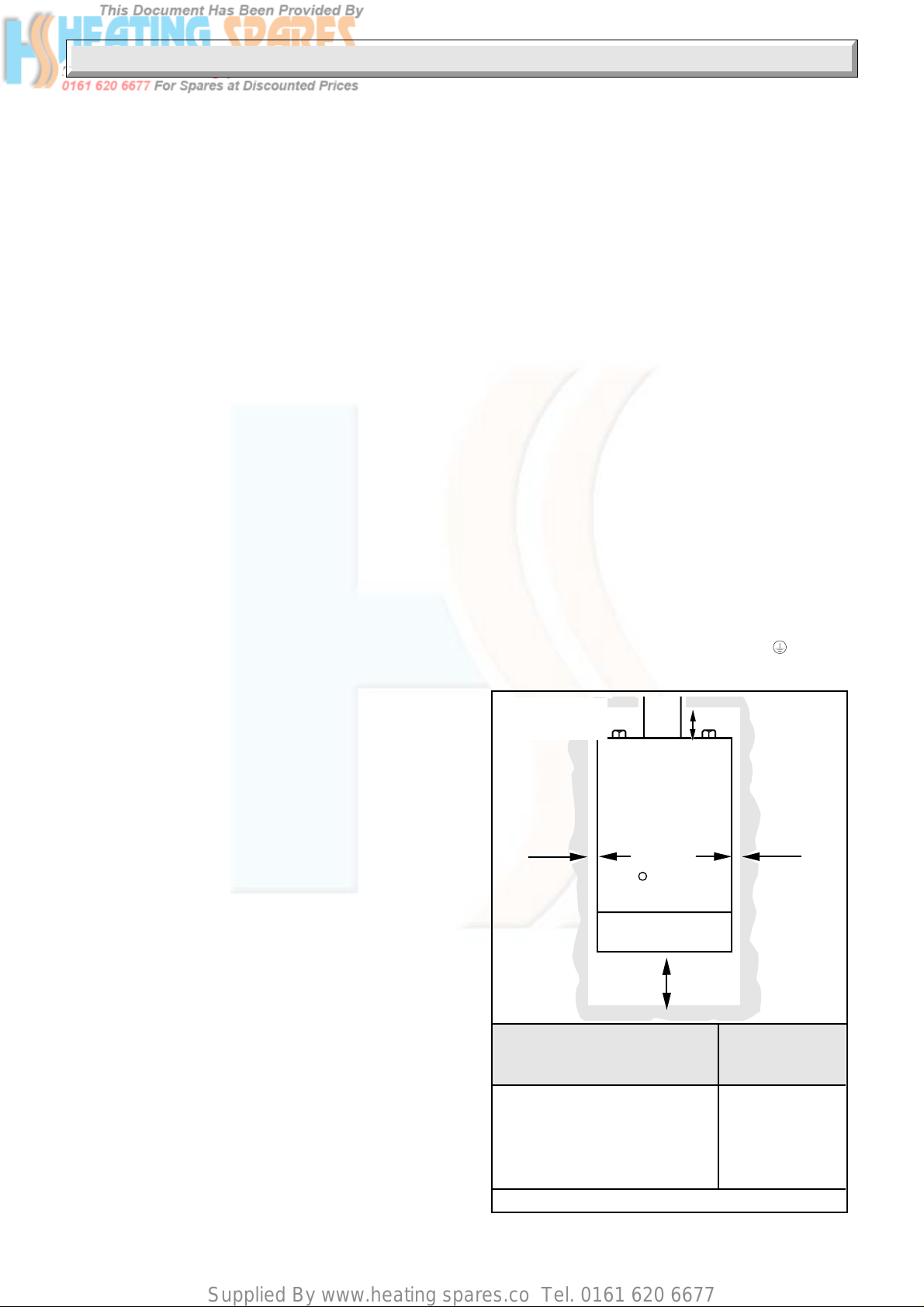
Boiler Clearance
The boiler must be positioned so that at least the minimum
operational and servicing clearances are provided, see diagram
1.
If fixtures are positioned close to the boiler they should be made
removable for access to pipework.
Enough space must be left in front of the boiler for servicing.
Boiler in a Compartment
If the boiler is fitted in a compartment or cupboard, purpose built
ventilation must be provided and kept clear.
Do not use the enclosed space for storage.
A
C
OPEN FLUE BOILERS
Minimum Clearances from
Walss, Ceiling, Floor, etc.
A L.H. and R.H. side of casing 25
B Top of casing 75
C Bottom of casing 150
D Front of boiler (from a
permanent surface 305
3
A
Diagram 1
221461C
Page 4

Supplied By www.heating spares.co Tel. 0161 620 6677
Instructions for Use
Safety Device
This appliance is fitted with a flue blockage safety device which
will shut down the appliance in the event of abnormal flue
conditions. This device is NOT a substitute for an independently
mounted Carbon Monoxide detector.
The safety device is reset, after three minutes by pushing in the
button “ F ” shown in diagram 3.
Note: The pilot will stay alight but the device must be reset.
Shut down can occur during certain climate conditions, but if it
recurs the chimney flue and air inlet into the room must be
checked and any problems found corrected by a competent
person, before the boiler is used again.
Lighting the Boiler
CAUTION
If the pilot flame goes out, either intentionally or by accident, no
attempt should be made to relight for at least three minutes.
Slide the controls cover off and clear, see diagram 2.
Make sure that the electrical supply to the boiler is switched off.
Identify the controls by referring to diagram 3.
Turn the control thermostat knob “A” fully anticlockwise to the
“OFF” position.
Push and hold in gas control knob “B”. Push and release igniter
button “C” until the pilot burner lights, look through window “D”.
When the pilot is alight keep gas control knob “B” pushed in for
about 15 seconds and then release.
If the pilot does not light or fails to stay alight, wait three minutes
and repeat the lighting operation, only this time keep knob “B”
pushed on for a little longer.
The flue blockage safety device may also need resetting, refer
to safety device instructions.
Make sure that the pilot is alight and stable.
Switch on the electrical supply to the boiler.
Check that all external controls are calling for heat.
Turn control thermostat knob “A” fully clockwise to “MAX” and
the main burner will light fully in about three to five seconds, look
through window “D”.
If the main burner does not light, the flue blockage safety device
may need resetting, refer to Safety Device instructions.
Adjust the control thermostat knob to the desired setting between
“MIN” and “MAX”. “MAX” is about 82
Replace controls cover.
o
C (180oF).
To Turn the Boiler Off
For short periods, turn control thermostat knob “A” anticlockwise
until “O” is against the setting point. The pilot will stay alight, to
relight the main burner turn control thermostat knob “A” clockwise
to the desired setting between “MIN” and “MAX”.
For longer periods, turn the control thermostat knob “A”
anticlockwise until “O” is against the setting point. Slide gas
control knob “B” to left and release, the control will automatically
reset. Switch off the electrical supply.
To relight, follow the full lighting procedure given above.
Cleaning
WARNING. This appliance contains metal parts (components)
and care should be taken when handling and cleaning, with
particular regard to edges.
Clean the casing by wiping it over occasionally with a wet cloth
or dry polishing duster.
Do not use abrasive cleaners.
CONTROLS
COVER
Diagram 2
2391
A. CONTROL THERMOSTAT KNOB
D
B. GAS CONTROL KNOB
C. IGNITER BUTTON
D. VIEWING WINDOW
F. FLUE BLOCKAGE SAFETY DEVICE
A
C
RESET BUTTON
BOILER
CONTROLS
221461C
F
4
5354
B
MODEL AND
SERIAL
NUMBER
PLATE
Diagram 3
Page 5

Supplied By www.heating spares.co Tel. 0161 620 6677
1 General Data
242
*
RETURN FLOW
115
DIA.
WATER
CONNECTIONS
GAS CONNECTION
360
36
*
INSIDE DIAMETER
OF SPIGOT FOR
100 mm (4in) NOMINAL
DIAMETER FLUE
11
600
40
WATER
CONNECTIONS
490
GAS
CONNECTION
110
225
FLUE
C
L
2409
86
43
98
OVERALL DIMENSIONS (given in millimetres)
1.1 Important Notice
This boiler is for use only on natural gas G20.
The boiler is delivered in one pack.
Wherever possible, all materials, appliances and components
to be used shall comply with the requirements of applicable
British Standards.
Where no British Standards exist, materials and equipment
should be fit for their purpose and of suitable quality and
workmanship.
This boiler must have fully pumped circuits, but is suitable for
use with open vented or sealed water systems.
This boiler is not suitable for fitting out of doors.
The boiler must not be installed in a bedroom, bed sitting room
or a room containing a bath or shower.
Open flue boilers must not be installed in private garages.
1.2 Sheet Metal Parts
WARNING. When installing or servicing the boiler care should
be taken when handling sheet metal parts to avoid any possibility
of personal injury.
1.3 Statutory Requirements
The installation of this boiler must be carried out by a competent
person in accordance with the relevant requirements of the
current issue of:
Manufacture’s instructions, supplied.
The Gas Safety (Installation and Use) Regulations, The Building
Regulations, The Building Standards (Scotland) Regulations
(applicable in Scotland), local Water Company Byelaws, The
Health and Safety at Work Act, Control of Substances Hazardous
to Health, The Electricity at Work Regulations and any local
applicable regulations.
300
Detailed recommendation are contained in the current issue of
the following British Standards and Codes of Practice:
BS4814, BS5400 Part and 2, BS5449, BS5446, BS6700,
BS6798, BS6891, BS7074 Part and 2, BS7478, BS7593,
BS7671.
Manufacturers’ instructions must not be taken as overriding
statutory requirements.
Diagram 1.1
1.4 Data
Weight of boiler: 40C - 20.1kg (44.3lb)
Water content: 40C - 0.50Litre (0.11gal)
Gas connection: Rc1/
Water connection: 22mm copper flow at right
Electrical supply: 240V - 50Hz fused at 3A
Data label: Bottom of inner case door.
Injector: 40C - Cat 98 - 1150
The Seasonal Efficiency Domestic Boilers UK (SEDBUK)
is 71.9%.
The value is used in the UK Government’s Standard Assessment
Procedure (SAP) for energy rating of dwellings. The test data
from which it has been calculated have been certified by B.S.I.
2
1.5 Range Rating
The boiler is range rated and may be adjusted to suit individual
system requirements.
The respective Table 1 gives the ratings and settings.
5
221461C
Page 6
Supplied By www.heating spares.co Tel. 0161 620 6677
1 General Data
1.6 B.S.I. Certification
This boiler is certificated to the current issue of BS6332 Part 1,
invoking the current issue of BS5258 Part for performance and
safety. It is, therefore, important that no alteration is made to
boiler without permission, in writing, from Hepworth Heating
Ltd.
Any alteration that is not approved by Hepworth Heating Ltd.,
could invalidate the B.S.I., certification of the boiler, the warranty
and could also infringe the current issue of the Statutory
1.7 Gas Supply
The gas installation must be in accordance with the current
issue of BS6891.
The supply from the governed meter must be of adequate size
to provide a steady inlet working pressure of 20mbar (8in wg) at
the boiler.
On completion, test the gas installation for soundness using the
pressure drop method and suitable leak detection fluid, purge
in accordance with the current issue of BS6891.
1.8 Electrical Supply
WARNING. This boiler must be earthed.
All system components shall be of the approved type and be
wired and connected in accordance with requirements the
current issue of BS7671 and any applicable local regulations.
Connection of the boiler and system controls to the mains
supply must be through a common isolator and must be fused
3A maximum. This method of connection should be by a fused
double pole isolating switch, which has a minimum contact
separation of 3mm on both poles. This switch should be readily
accessible and preferably adjacent to the appliance. It should
supply the appliance only and be easily identifiable as so doing.
Wiring to the boiler must be insulated PVC flexible type to the
current issue of BS6500 Table 16, not less than 0.75mm
0.20mm).
2
(24/
1.12 Timber Frame Buildings
If the boiler is to be installed in a timber frame building it should
be fitted in accordance with the Institute of Gas Engineers
document IGE/UP/7/1998. If in doubt seek advice from the local
gas undertaking or Hepworth Heating Ltd.
1.13 Heating System Controls
The heating system should have installed: a programmer and
room thermostat controlling the boiler.
Thermostatic radiator valves may be installed in addition to the
room thermostat.
Note: For further information, see The Building Regulations
1991 - Conservation of fuel and power, 1995 edition - Appendix
G, table 4b.
B
0003M
1.9 Draining Tap
A draining tap must be provided at the lowest points of the
system which will allow the entire system, boiler and domestic
hot water cylinder to be drained.
Draining taps shall be to the current issue of BS2879.
1.10 Safety Valve
A safety valve need not be fitted to an open vented system.
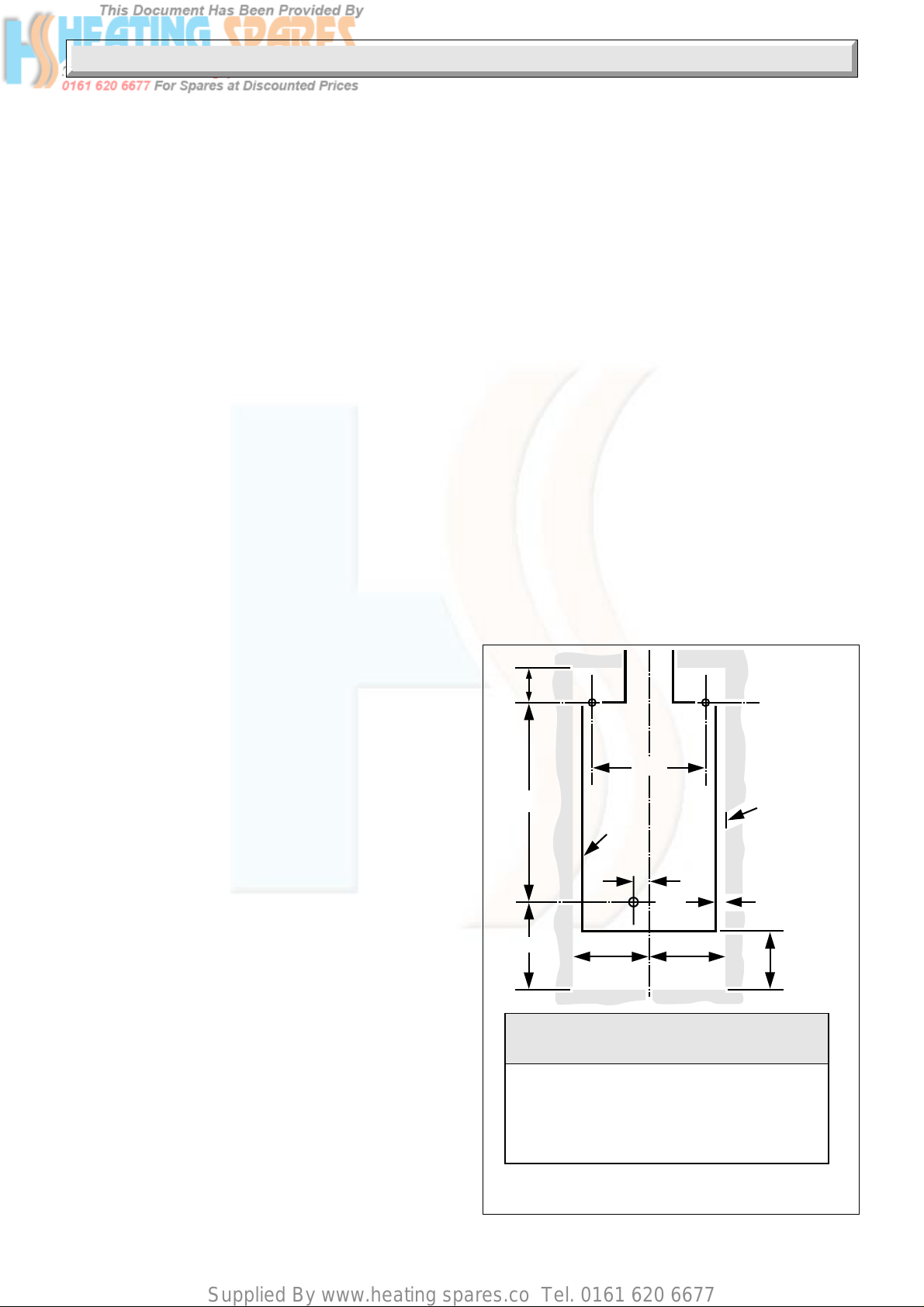
1.11 Clearances
The boiler position should be such that the clearances shown in
diagram 1.2 are achieved.
Additional clearances may be required for installation.
If fixtures are positioned next to the boiler they should be made
removable for access to pipework.
Sufficient clearance must be left in front of the boiler for
servicing.
The casing side grilles must be kept clear at all times.
The boiler must be mounted on a flat wall which is sufficiently
robust to take its weight.
300
518
232
Minimum Clearances
from Walls, Ceiling,
Floor, Cupboard, Worktops etc.
Boiler
Outline
46
200 200
A L.H. and R.H. side of casing 25
B Top of casing 75
C Bottom of casing 150
D Front of boiler (from a
permanent surface) 305
BOILER FIXING DIMENSIONS
AND MINIMUM CLEARANCES
Minimum
clearance
limit
A
C
Diagram 1.2
221461C
6
Page 7

Supplied By www.heating spares.co Tel. 0161 620 6677
2 Flue and Ventilation
Important note
The boiler is fitted with a Flue Blockage Safety Device, which
will shut down the boiler if there is an unacceptable spillage of
products at the draught diverter.
This safety device MUST NOT under any circumstances be
interferred with or put out of action.
The safety device must only be replaced with the Glow-worm
parts.
2 Flue Connection
The integral draught diverter on the boiler makes the combustion
performance independent of the conditions in the secondary
flue, but in common with other fuels an efficient flue is necessary
to ensure a trouble free installation.
The flue outlet on the boiler is designed to take flue pipes to
BS567. If a flue pipe to BS715 is to be used an adapter must
be fitted to the boiler flue socket.
The flue must be in accordance with the current issue of
BS5440 Part 1.
Give maximum possible vertical rise from the boiler, at least a
minimum of 600mm, before any offset or bend. The use of 90
bends is not recommended.
An existing flue must be lined and end, at least above ridge
height, with a certificated terminal.
A chimney previously used for solid fuel must be swept and any
damper or register plate left in the locked open position or
removed.
2.1 Boilers in a Compartment
Where the installation of the boiler will be in an unusual location,
special procedures are necessary, the current issue of BS6798
gives detailed guidance on this aspect.
A compartment used to enclose the boiler must be designed
and constructed specifically for this purpose.
An existing cupboard or compartment modified for the purpose
may be used. Details of essential features of cupboard or
compartment design are given in the current issue of BS6798.
The doorway opening should be of sufficient size to allow for
easy removal of the boiler.
Where the boiler is fitted in a cupboard or compartment,
permanent high and low level ventilation must be provided.
The minimum ventilation areas required are given in Table “A”.
2.2 Boiler Installed in a Room or Space
A purpose designed ventilation opening must be provided on an
outside wall of the premises, refer to the current issue of
BS5440 Part 2 for further information.
The opening may be either, directly into the room or space
containing the boiler or into an adjacent room or space which
has an internal permanent air vent of the same size as the room
containing the boiler.
DO NOT ventilate through a private garage, bedroom, bedsitting
room or a room containing a bath or shower.
Air vents through a cavity wall must be ducted.
When the boiler is installed in a space already containing a fuel
burning appliance account must be taken of the TOTAL air
requirement.
2.3 Extract Fans
If an extract fan is fitted in the premises there is a possibility that
if adequate air openings are not provided spillage of products
from the boiler may occur.
When openings are fitted in accordance with the
recommendations of the current issue of BS5440 Part 1 and this
Section, extract fans should not cause spillage, but where such
an installation is found spillage tests as the current issue of
BS5440 Part 1 must be carried out.
The necessary action should then be taken.
See also Section 6.6.
o
TABLE "A" COMPARTMENT AIR VENTS
ECONOMY PLUS 40C
Ventilation
Requirements
Air from room or
internal space
Air direct from
outside
TABLE "B" ROOM/SPACE AIR VENTS
ECONOMY PLUS 40C
Effective area
of vent
Table 1 ECONOMY PLUS 40C
Range Rating
Nominal kW
Heat
Input (GROSS)
Btu/h
Nominal kW
Heat
Output
Btu/h
Burner m bar
Setting
Pressure
in.w.g
Burner Injector Marking: 1.25
Burner Injector Size: 1.25 X 7
Pilot Injector Marking: 7218
High Level
Vent Area
132cm
66cm
2
2
35cm
Low Level
Vent Area
264cm
132cm
2
min medium max
11.14 12.90 14.65
38,000 44,000 50,000
8.80 10.26 11.70
30,000 35,000 40,000
7.8 10.4 13.1
3.1 4.2 5.3
2
2
7
221461C
Page 8

Supplied By www.heating spares.co Tel. 0161 620 6677
3 Water Systems
GALLONS/MINUTE
LITRES/MINUTE
FUELSAVER 40C
WATER PRESSURE LOSS
(m head of water)
WATER PRESSURE LOSS
(in head of water)
0
1
24
35
0
5
10
15 20 25
55
50
45
40
35
30
25
20
15
10
5
0
1.4
1.2
1.0
0.8
0.6
0.4
0.2
0
6927
Notes:
PUMP
The pump with integral valves, if possible, should be fitted in the
flow pipework from the boiler, to produce a temperature difference
across the boiler of 11
See diagram 3.1 for pressure loss across the boiler.
High resistance microbore systems may require a higher duty
pump.
BYPASS
A bypass
The flow through the boiler must not be allowed to fall below:
40C - 10.5L/min (2.3gall/min)
whilst the burner is alight.
must be fitted, see diagram 3.2.
3.1 Open (Vented) Water System
For an open (vented) water system the boiler must be supplied
from an unrestricted water supply taken from a cold feed and
expansion cistern situated at a maximum height of 27.5 metres
(90ft) above the boiler.
The cold feed supply must be 15mm minimum size.
It is important that the relative position of the pump, cold feed
and open vent are as shown in diagram 3.2.
3.2 Domestic Hot Water Cylinder
The domestic hot water cylinder must be of the double feed, fully
indirect type. Single feed, self priming cylinders are not
recommended.
3.3 Inhibitor
Attention is drawn to the current issue of BS5449 and BS7593
on the use of inhibitors in central heating systems.
If an inhibitor is to be used, contact a manufacturer for their
recommendations for the best product to use.
When installing a boiler in an existing system, whether or not
using an inhibitor, take special care to drain the entire system,
including the radiators, then thoroughly cleaning out before
fitting the boiler and adding the inhibitor.
3.4 Sealed Water Systems
The installation should comply with the appropriate requirements
of the current issue of BS4814, BS5449, BS6759, BS6798 and
BS7074 Part 1 and 2.
See diagram 3.3 for a diagrammatic layout.
3.5 Safety Valve
A safety valve must be fitted to a sealed water system.
It shall be preset, nonadjustable with a lift pressure of 3bar,
incorporating seating of a resilient material, a test device and a
connection for drain.
The drain from the safety valve must be routed clear of any
electrical fittings and positioned so that any discharge can be
seen.
221461C
o
C (20oF).
PRESSURE LOSS OF BOILER
8
450mm
MIN.
HEIGHT
1150mm
MIN.
150
mm
MIN.
BOILER
Open (vented) system.
Recommended
relationship between
pump, cold feed and
vent.
22 mm (MIN) VENT
FEED AND
EXPANSION
CISTERN
15mm (MINIMUM)
COLD FEED
15mm (MINIMUM)
BY-PASS WITH
LOCKSHIELD VALVE
ALTERNATIVE
PREFERRED
PUMP
150mm
MAX
Diagram 3.1
RET.
CYLINDER
Diagram 3.2
0392
FLOW
RET.
HEATING
FLOW
Page 9

Supplied By www.heating spares.co Tel. 0161 620 6677
3 Water Systems
(Make-up
alternatives)
3 LITRES (0.66 gals)
MAKE-UP BOTTLE
(if required)
NON-RETURN
VALVE
HEATING
CIRCUIT
AUTO
AIR
VENT
FLOW
RETURN
DRAIN
COCK
BOILER
15mm (min)
BY-PASS WITH
LOCKSHIELD
VALVE
SAFETY
VALVE
AIR
RELEASE
POINT
FILLING POINT
CIRCULATING
PUMP
PRESSURE
GAUGE
EXPANSION
VESSEL
5812
SEALED WATER SYSTEM DIAGRAMMATIC LAYOUT
3.6 Expansion Vessel
A diaphragm type expansion vessel, conforming to the current
issue of BS4814 (see also the current issue of BS7074 Part 1
and 2) must be connected at a point close to the inlet side of the
circulating pump, see diagram 3.3, unless laid down differently
by the manufacturer.
The expansion vessel volume depends on the total water
system volume and the initial system design pressure. For any
system an accurate calculation of vessel volume size is given
in the current issue of BS7074 Part 1.
Example: For an initial system design pressure of 0.7bar the
minimum total vessel volume required is 0.063xTotal System
volume.
Guidance is also given in the current issue of BS5449.
The charge pressure must not be less than the static head of the
system, that is, the height of the highest point of the system
above the expansion vessel.
The water capacity of the boiler is given in Section 1.
3.7 Pressure Gauge
A pressure gauge with a set pointer and covering at least the
range of 0 to 4 bar (0 to 60lb/in2) shall be permanently fitted to
the system in a position where it can be seen when filling the
system.
EXPANSION VESSEL SYSTEM
EXPANSION VESSEL
PRESSURE (BAR)
INTIAL SYSTEM
PRESSURE (BAR)
EXPANSION VESSEL
VOLUME (LITRES)
EXPANSION VESSEL
PRESSURE (BAR)
INTIAL SYSTEM
PRESSURE (BAR)
EXPANSION VESSEL
VOLUME (LITRES)
A = SYSTEM VOLUME
0.5 1.0
A X 0.075 A X 0.126
1.0 1.5
A X 0.098 A X 0.171
Diagram 3.3
0.5
1.0
Diagram 3.4
9
221461C
Page 10

Supplied By www.heating spares.co Tel. 0161 620 6677
3 Water Systems
3.8 Domestic Hot Water Cylinder
SINGLE FEED INDIRECT CYLINDERS ARE NOT SUITABLE.
The domestic hot water cylinder must be of the indirect coil type.
It must be suitable for working at a gauge pressure of 0.35bar
above the safety valve setting.
3.9 Water Make-up
Provision should be made for the replacing the water loss from
the system using a make up bottle mounted in a position higher
than the top point of the system, connected through a nonreturn valve to the return side of either the heating circuit of the
domestic hot water cylinder.
Alternatively, provision for make up can be made by using a
filling loop.
3.10 Filling a Sealed Water System
Provision for filling the system at low level must be made. Three
methods are shown in diagram 3.5. There must be no permanent
connection to the mains water supply, even through a nonreturn valve.
METHOD 1
TEMPORARY
HOSE
SUPPLY
PIPE
METHOD 2
TEMPORARY
HOSE
SUPPLY
PIPE
METHOD 3
CISTERN
HOSE
UNIONS
SUPPLY STOP
VALVE
DOUBLE CHECK
VALVE ASSEMBLY
HOSE
UNIONS
SUPPLY STOP
VALVE
OVERFLOW
SERVICING
VALVE
COMBINED
CHECK VALVE
AND VACUUM
BREAKER
SERVICING
VALVE
SERVICING
VALVE
PRESSURE
REDUCING
VALVE
HEATING
SYSTEM
HEATING
SYSTEM
HEATING
SYSTEM
3132
4 Installation
4.1 Appliance Preparation
Remove the controls cover by pulling it forwards and off, see
diagram 4.1.
Remove the boiler from the carton and lay it on its back.
The side grilles are packed in the bottom of the carton.
Remove the outer case by undoing the screws at the bottom
and unhooking at the top, see diagram 4.1.
Remove the two screws and attach the side grilles by hooking
over the top of the side panel and secure, see diagram 4.1.
SUPPLY
STOP VALVE
SUPPLY
PIPE
HOSE
UNIONS
DOUBLE CHECK
VALVE ASSEMBLY
FILLING SEALED
WATER SYSTEMS
Diagram 3.5
4.2 Appliance Fitting
Refer to diagram 1.2 for fixing screw positions and minimum
clearances.
Mark position of the three fixing screws.
Drill and plug the holes, suitable for No10x2in woodscrews.
Fit the screws, leave about 6mm proud.
Hook the boiler on to the lower screw and keyhole slots at the
top, tighten all screws.
Connect the system pipework to the boiler.
Fix the flue to the flue hood in accordance with normal practice.
221461C
10
Page 11

Supplied By www.heating spares.co Tel. 0161 620 6677
4 Installation
4.3 Gas and Water Connection
Connect the gas supply to the Rc1/2in gas cock.
The whole of the gas installation, including the meter, should be
inspected, tested for soundness and purged in accordance with
the current issue of BS6891.
Connect the water to the boiler, using nuts and olives supplied,
to BS2871 copper tube.
OUTER
CASE
2410
SIDE
GRILLE
4.4 Casing
Refit the outer casing by hooking on at the top and securing with
the screws previously removed, see diagram 4.1.
Make sure that the side grilles are kept clear.
5 Electrical Wiring
5.1 Electrical Connection
WARNING. The boiler must be earthed and have a permanent
mains supply.
To remove the control box release the two screws at the front,
see diagram 5.1, lower the box until it is clear then push
backwards to disengage the hinge at the rear, see diagram 5.1.
Take care not to damage the thermostat and capillaries.
Thread the mains lead through the clamp in the rear of the
control box cover and connect to the terminal strip.
The mains cable outer insulation must not be cut back external
to the cable clamp.
When making connections, make sure that the earth conductor
is made of a greater length than the current carrying conductors,
so that if the cable is strained the earth conductor would be the
last to become disconnected.
5.2 Pump and External Controls Connections
The pump must be wired into the boiler control box as shown in
diagram 5.2.
Any external controls must only be wired to interrupt the Red link
between terminals 9 and SL.
Take the strain relief grommets from the loose items pack.
Place around the external controls and pump connection cables
respectively.
Squeeze the sides of the grommets when pushing them into the
obround holes in the rear of the control box, see diagram 5.1.
Make sure the supply cable and all external cables are secured.
SECURING
SCREW
CONTROL
COVER
SECURING
SCREW
Diagram 4.1APPLIANCE PREPARATION
5.3 Testing - Electrical
Checks to ensure electrical safety should be carried out by a
competent person.
After installation of the system, preliminary electrical system
checks as below should be carried out.
1. Test insulation resistance to earth of mains cables.
2. Test the earth continuity and short circuit of all cables.
3. Test the polarity of the mains.
The installer is requested to advise and give guidance to the
user of the controls scheme used with the boiler.
STRAIN
SECURING
SCREWS
FASTENER
RELIEF
GROMMET
5352
11
TERMINAL
STRIP
RETAINING
STRAP
EARTH
POST
Diagram 5.1CONTROL BOX
221461C
Page 12

Supplied By www.heating spares.co Tel. 0161 620 6677
5 Electrical Wiring
CIRCULATION
PUMP
240V~ 50Hz
PERMANENT
MAINS SUPPLY
FUSED AT 3A
SWITCHED
CONTROL
TIME SWITCH
PROGRAMMER
ETC.
(if fitted)
Remove Red Link
between 9 and SL
when fitting a time
control etc.
(If link is not
removed the
circulation pump
will run constantly. )
BROWN
L
BLUE
N
GRN/YELLOW
BROWN
L
BLUE
N
LSL
N
SL
L
N
BROWN
BLUE
GRN/YELLOW
5353
GRN/YEL
CHASSIS
EARTH
89
POST
7
GAS VALVE
F.B.S.D.
BROWN
89
7
BLUE
PURPLE
RED
RED
BROWN
WHITE
7
89
3
6
COMBINED THERMOSTAT AND
PUMP OVERRUN
Diagram 5.2WIRING DIAGRAM FOR CONTROL BOX.
6 Commissioning
6.1 All Systems
Make sure that the system has been thoroughly flushed out with
cold water without the pump in place. Refit the pump, fill the
system with water, making sure that all the air properly vented
from the system and pump.
Before operating the boiler make sure that all external controls
are calling for heat.
6.2 Sealed Water Systems Only
Flush the whole system with cold water without the pump in
place. Refit the pump and fill until the pressure gauge registers
1.5bar (21.5lbf/in2). Clear any airlocks and check for water
soundness.
Check the operation of the safety valve, by allowing the water
pressure to rise until the valve opens. The valve should open
within +/-0.3bar (+/-4.3lbf/in
Where this is not possible conduct a manual check and test.
Release cold water to initial system design pressure.
The set pointer on the pressure gauge should be set to coincide
with the indicating pointer.
6.3 Initial Lighting and Testing - All Systems
Refit the outer case, see diagram 4.1.
Identify the controls be reference to diagram 6.1.
Turn the control thermostat control knob “A” to “O” the Off
position, see diagram 6.1.
2
) of the 3bar preset pressure.
Remove the pressure test point screw “K” and fit a suitable
pressure gauge.
Turn the electrical supply on and check that the pump is
working.
Open all windows and put out any naked lights, pipes, cigarettes
and the like.
Turn on the main gas supply and purge in accordance with the
current issue of BS6891.
Turn the boiler gas service cock “J” to On.
Note. Make sure that the flue blockage safety device reset
button “M” is fully pushed in.
Push in control button “B”, keep pushed in and at the same time
operate the piezo button “C” until the pilot burner lights. After the
pilot burner lights keep the button “B” pushed in for about 15
seconds. If the pilot burner fails to light or stay alight a safety
device prevents immediate relighting. Do not attempt to relight
until the safety device has reset.
Note. Should the boiler fail to operate correctly refer to Fault
Finding Section.
Check the length of the pilot flame, it should envelop the
thermocouple tip as shown in diagram 7.7. The pilot rate can be
adjusted by turning screw “H”, having first removed the gas
valve cover by releasing the screws, see diagram 6.1.
Test pilot supply connections for soundness with a suitable leak
detection fluid.
221461C
12
Page 13

Supplied By www.heating spares.co Tel. 0161 620 6677
6 Commissioning
Fit the outer case, secure with the screws previously removed.
Make sure that the pilot is alight and stable, view through
window “G”.
Set the control thermostat knob “A” between “MIN” and “MAX”
(“MAX” is about 82
smoothly. Check all gas connections for soundness with a
suitable leak detection fluid.
Note. Should the boiler fail to operate correctly refer to Fault
Finding Section.
To set the burner pressure operate the boiler for 10 minutes,
remove the gas valve cover, if not already removed, adjust the
gas pressure by screw “H” until the required pressure is obtained,
see the relevant Table 1 for setting pressures.
Stick the self adhesive arrow, from the loose items pack, in the
appropriate space beneath “MIN” and “MAX” column on the
data label.
Should any doubt exist about the gas rate this should be
checked at the meter, using a stop watch to time at least one
cubic foot of gas consumption.
Replace the gas valve cover.
Remove the pressure gauge and refit the screw, make sure that
a gas tight seal is made.
o
C (180oF) and check that the burner lights
6.4 Testing
Check the operation of the flame failure device on the boiler to
make sure that the gas valve shuts down within 60 seconds,
indicated by a “click” from the valve.
6.5 Flushing
Allow the system to reach maximum working temperature and
examine for water leaks.
The boiler should then be turned off and the system drained as
rapidly as possible whilst still hot.
Refill the system and vent and check for water soundness as
before.
6.6 Adjustment - All Systems
When commissioning the system the boiler should first be fired
on full service, that is, central heating and domestic hot water.
The system should then be balanced, adjusting the pump and
lockshield valve as necessary. Having achieved a satisfactory
condition operate the boiler with the bypass fully closed on
minimum load, normally this will be central heating with one
radiator, in the main living area working. The valve should then
be gradually opened to achieve a flow rate of 7.8L/min (1.7gal/
min).
Under no circumstances should this valve be left in the fully
closed position.
Operate the boiler again on full service and check the balancing,
making further adjustments as necessary.
If thermostatic radiator valves are fitted care must be taken to
make sure adequate flow through the boiler when they close,
refer to the current issue of BS7478.
Do not attempt to adjust the thermostat calibration screw.
Test the boiler for spillage of the flue products at the draught
diverter as detailed in the current issue of BS5440 Part 1. See
also Section 2.3.
A
C
M
A. CONTROL THERMOSTAT KNOB
B. GAS CONTROL KNOB
C. IGNITER BUTTON
G. VIEWING WINDOW
H. GAS RATE ADJUSTMENT SCREW
(UNDER COVER SCREW)
G
H
K
L
J. GAS SERVICE COCK
K. PRESSURE TEST POINT
L. PILOT BURNER
ADJUSTMENT SCREW
M. FLUE BLOCKAGE SAFETY
DEVICE RESET SWITCH
5354
B
J. (Shown Off)
MODEL AND SERIAL
NUMBER PLATE
Diagram 6.1
13
221461C
Page 14

Supplied By www.heating spares.co Tel. 0161 620 6677
6 Commissioning
6.7 Adjustment - Sealed Water Systems
Sealed water systems should be adjusted to the initial design
pressure and the set pointer repositioned.
6.8 Instruct the User in the Correct Operation
of the Boiler
Hand the User Instructions to the user for their use.
Instruct and demonstrate the safe and efficient operation of the
boiler, heating system and domestic hot water system.
Advise the user, that to ensure the continued efficient and safe
operation of the boiler it is recommended that it is checked and
serviced at regular intervals. The frequency of servicing will
depend upon the particular installation and usage, but in general
once a year should be enough.
7 Servicing and Replacement of Parts
For the continued efficient and safe operation of the boiler it is
recommended that it is checked and serviced at regular intervals.
The frequency will depend upon the particular installation and
usage, but in general once a year should be enough.
It is the Law that any servicing be carried out by a competent
person.
Replacement of parts must be carried out by a competent
person.
Before starting a service or replacing parts isolate the gas and
electrical supplies.
Unless stated otherwise all parts are replaced in the reverse
order to removal.
It is the Law that servicing is carried out by a competent person.
Draw attention, if applicable, to the current issue of the Gas
Safety (Installation and Use) Regulations section 35, which
imposes a duty of care on all persons who let out any property
containing a gas appliance.
Advise that the boiler is fitted with a safety device and refer to
the instructions for use.
Advise the user of the precautions necessary to prevent damage
to the system and building in the event of the heating system
being out of use during frost and freezing conditions.
Reminder. Leave these instructions with the user.
Advise the user that the ‘Benchmark’ logbook should be
completed by the installation engineer on completion of
commissioning or servicing.
7.2 Main Burner - Service
Generally follow the instructions given in Section 7.1.
With the main burner removed brush or vacuum any deposits
away, make sure that the flame ports are clear.
Do not use a brush with metallic bristles.
Note. Alternative type of burner are fitted to some models.
Remove lint arrester from main burner and clean it thoroughly
by brushing or vacuuming, see diagram 7.5 for Bray burner and
diagram 7.6 for Furigas burner.
7.1 Heating Body - Service
Remove the controls cover by pulling it forwards and off.
Remove the outer casing by releasing the screw at the bottom
and unhooking at the top.
Remove the inner casing by releasing the wing nuts at the top
and the screws at the bottom, see diagram 7.1.
Remove the combustion chamber front by unscrewing the wing
nut at the bottom front and the four screws, see diagram 7.2.
Disconnect the ignition lead from the electrode and unscrew
thermocouple nut to release, see diagram 7.3.
Support the main burner and release pilot tubing nut at the base
of burner, release pilot tube. The pilot injector can now be
removed by unscrewing, see diagram 7.3.
Disengage the main burner from the main injector. Raise the
burner up through the combustion chamber to remove. Take
care not to damage the side insulation.
Place the burner to one side.
Cover the combustion chamber and injector with a sheet of
paper.
Remove the flue cleaning door, see diagram 7.1.
Remove the screws securing the draught diverter baffle and
lower out as shown in diagram 7.4.
Brush away any deposits from the heat exchanger paying
particular attention to the gap between the fins.
Remove the paper together with any debris.
When replacing parts make sure that the draught diverter is
refitted correctly.
FLUE CLEANING DOOR
WING
NUT(S)
INNER CASING
SECURING
SCREWS
ACCESS FOR SERVICING
2398
INNER
CASE
Diagram 7.1
221461C
14
Page 15

Supplied By www.heating spares.co Tel. 0161 620 6677
7 Servicing and Replacement of Parts
7.3 Main Injector
Generally follow the instructions given in Section 7.1.
With the main burner removed the injector can be unscrewed
and replaced as necessary, using a new sealing washer.
If cleaning do not use a wire or sharp instrument on the hole.
When replacing the main burner make sure that it is pushed fully
home onto the injector and that the guides are engaged on the
injector manifold.
COMBUSTION
CHAMBER
FRONT
PANEL
SECURING
SCREWS
23971049
DRAUGHT DIVERTER
AND BAFFLE
BAFFLE
SECURING
SCREW(S)
DRAUGHT
DIVERTER
BAFFLE
Diagram 7.4
BURNER
ASSEMBLY
LINT ARRESTER
SECURING SCREW
AND WASHER
0929
0928
WING NUT
ACCESS FOR SERVICING
MICA WINDOW
PILOT
SHIELD
SECURING
SCREWS
PILOT
INJECTOR
ADAPTOR
OLIVE
PILOT
TUBING
NUT
PILOT ASSEMBLY
SIDE BAFFLES
Diagram 7.2
M3
SCREW
ELECTRODE
IGNITION
LEAD
(clear end)
THERMOCOUPLE
THERMOCOUPLE
NUT
Diagram 7.3
LINT ARRESTER
LINT ARRESTER
(BRAY)
BURNER
ASSEMBLY
LINT
ARRESTER
LINT ARRESTER
(FURIGAS)
Diagram 7.5
0927
LINT ARRESTER
SECURING PLATE
SCREWLOOSEN ONLY
Diagram 7.6
15
221461C
Page 16

Supplied By www.heating spares.co Tel. 0161 620 6677
7 Servicing and Replacement of Parts
7.4 Pilot Burner and Injector - Service
Generally follow the instructions given in Section 7.1.
With the main case, inner case and controls cover etc., removed
as above, pull off ignition lead from the electrode.
Unscrew the tubing nut at the base of the pilot burner, releasing
the pilot pipe. Remove the pilot injector by unscrewing from the
pilot burner.
Unscrew the thermocouple nut to release the thermocouple
from the pilot burner.
Support the main burner and remove the two screws and
washers securing the pilot burner and shield to burner.
Remove the complete assembly.
Lift the pilot burner off.
Take care not to damage the electrode.
When replacing make sure the spark gap is as shown in diagram
7.7.
Check the pilot burner flame lengths are as shown in diagram
7.7.
7.5 Thermocouple
Generally follow the instructions given in Section 7.1.
Unscrew the thermocouple nut to release from the pilot burner,
see diagram 7.3.
Disconnect the thermocouple from the gas valve, see diagram
7.9.
Use the old thermocouple as a pattern when fitting the new one.
Do not tighten more than a quarter turn beyond finger tight at the
gas valve.
Check the electrode spark gap, see diagram 7.7.
THERMOSTAT
PHIAL/OVERHEAT
CUT-OFF
EXT. SCREW (4)
PILOT
TUBE
NUT
CUT-OFF
SECURING
SCREW(S)
OVERHEAT
CUT-OFF
HEAT
EXCHANGER
RETAINING
CLIP
THERMOSTAT
PHIAL
Diagram 7.8
'O' RING
0951
2414
14 to 17mm
SPARK GAP
3 TO 4mm
ELECTRODE
PILOT FLAME AND
SPARK GAP
14 to 17mm
THERMOCOUPLE
Diagram 7.7
1053
GAS
VALVE
CONNECTORS
'O' RING
THERMOCOUPLE NUT
ELECTRICAL
INTERRUPTER
CONNECTOR
GAS VALVE ASSEMBLY
GAS SERVICE
COCK
(Shown Off)
EXT.
SCREW (4)
Diagram 7.9
221461C
16
Page 17

Supplied By www.heating spares.co Tel. 0161 620 6677
7 Servicing and Replacement of Parts
7.6 Electrode
Generally follow the instructions given in Section 7.1.
Unscrew the electrode from the pilot shield.
When refitting check that the spark gap is as diagram 7.7.
7.7 Over Heat Cutoff Device
Generally follow the instructions given in Section 7.1.
Remove the screws securing the over heat cutoff device to the
clamp, see diagram 7.8.
Release the cutoff connectors at the gas valve, see diagram 7.9.
Remove the screw retaining the grommet plate to the rear panel
to release plate, see diagram 7.10.
Carefully remove, one at a time, the cables of the cutoff through
the grommet.
When reassembling use a little of the heat sink compound,
supplied, on the face of the cutoff to make sure of a good contact
with the pipe also make sure it is correctly located.
7.8 Gas Valve
Generally follow the instructions given in Section 7.1.
Remove screw to release gas valve cover.
Disconnect all leads and pipes at valve.
Undo the four screws each side of the valve to release the
service cock and burner supply tube, take care not to damage
the “O” rings.
Remake all connections.
Do not tighten the thermocouple nut more than a quarter turn
beyond finger tight.
It will be necessary to purge pipework and gas valve before
relighting, refer to Commissioning.
7.12 Control Thermostat
Gain access generally as Section 7.1.
Remove and support the control box.
Remove the control knob and electrical connections from the
control thermostat body.
Pull off the connectors from the control thermostat terminals.
Remove the two screws securing the control thermostat to the
control box. The control thermostat can now be removed.
When replacing smear the control thermostat phial with a little
heat sink compound, supplied, before fitting into the pocket.
0787
SECURING
SCREW for
Grommet Plate
GROMMET
PLATE
(behind duct)
7.9 Electrical Control Box
Remove controls cover and outer casing as above.
Remove retaining clip from boiler thermostat phial pocket and
withdraw the phial, see diagram 7.8.
Remove the control box by undoing the two fixing screws at the
front and lower the front of the box until it is clear of the cover.
Push the box towards the rear of the boiler to disengage the hinge
and lower, see diagram 5.1.
Withdraw the control thermostat capillary through the bottom of
the air duct.
Disconnect cables (a) mains, L. N and E (b) pump at terminal 8,
7 and earth stud, (c) cables at gas valve, (d) disconnect any
remote controls at terminals 9 and SL.
When replacing refer to diagram 5.2 for electrical connections.
Smear the control thermostat phial with heat sink compound
and make sure it is secured with the retainer, in the pocket.
7.10 Piezo Unit
Gain access generally as Section 7.1.
Disconnect ignition lead and remove backing nut from piezo
unit.
7.11 Ignition Lead
Gain access generally as Section 7.1.
Disconnect the ignition lead at both ends.
When replacing the clear end fits to the electrode.
OVERHEAT CUT-OFF
REMOVAl
GAS VALVE
COVER
RETAINING
CLIP
SOLENOID
GROMMET
Diagram 7.10
3782
SECURING
SCREW
ELECTRICAL
CONNECTORS
Diagram 7. 11
17
221461C
Page 18

Supplied By www.heating spares.co Tel. 0161 620 6677
7 Servicing and Replacement of Parts
7.13 Replacement of Flue Blockage Safety
Device
Gain access generally as section 7.1 and Diagram 7.12
Inset A. Remove phial assembly by removing the brass knurled
screw(s).
Inset B. Carefully remove phial and capillary through back of
boiler.
Inset C. Having opened control box remove the electrical
connections from the flue blockage safety device, the locknut
and capillary retaining clip. Fit new flue blockage safety device
in reverse order, making sure that the capillary is secure and
there is sufficient slack at the control box to allow the box to be
opened and closed without damaging the capillary.
Important. Make sure the phial assembly is correctly located on
the two locating studs.
When refitting make sure that the capillary is clear of hot
surfaces, to avoid nuisance shut down of boiler.
BRASS
KNURLED
NUTS
BRACKET
INSET C
FLUE
BLOCKAGE
SAFETY
DEVICE
PHIAL
5389
INSET BINSET A
GROMMET
PLATE
(behind duct)
5390
SECURING
SCREW for
Grommet Plate
LOCKNUT
PLASTIC
RETAINING
CAPILLARY
CLIP
221461C
18
5400
Diagram 7.12
Page 19

Supplied By www.heating spares.co Tel. 0161 620 6677
8 Fault Finding
Fault and Cause
8.1 Pilot Goes Out after a Period
of Remaining Alight
Front cover not correctly fitted. Fit parts correctly.
Flue parts not fitted or sealed properly. Seal cavity or fit flue parts correctly as described in
Electrical supply failure causing
over heat device to operate. Relight pilot.
Pump incorrectly wired. Connect pump in accordance with diagram 5.2.
Overheat cutoff operating. Refer to Section 8.3.
8.2 Main Burner Will Not Light
External, remote controls not “On.” Check that any remote controls are calling for heat.
Control thermostat not on. Check control thermostat is in an “On” position, see also
Flue Blockage Safety Device tripped. Reset, refer to section 6
Remedy
Installation Instructions.
Section 8.9.
If Flue Blockage Safety Device repeatedly requires resetting, call a service engineer
8.3 Control Thermostat Will Not Cut Out
Control thermostat phial not fitted in pocket. Fit phial in pocket.
Faulty control thermostat. Replace control thermostat.
8.4 Overheat Cutoff Device
Cuts Out Prematurely
Air in heating body. Vent system. Alter system layout if necessary.
Water circulation low or stopped. Pump not functioning correctly. Check pump is
Overheat cutoff device operates before boiler
cycles on maximum control thermostat setting. Change faulty overheat cutoff device.
The correctly set overheat cutoff device operates
prematurely. There is no air in the heating body
and water circulation satisfactory. Change faulty heating body.
Pump not functioning correctly. Check pump is wire directly to the boiler.
8.5 Insufficient Heat
Control thermostat set too low. Increase setting.
Inlet gas pressure inadequate. Increase gas pressure.
Governor setting incorrect.
(make sure control thermostat is on maximum setting). Check burner pressure against data label.
8.6 Appliance Noisy in Operation*
Overgassed. Check burner pressure against data label and adjust only if
Complete lack of water. Check system controls for correct installation or correct type
Air in system. Remove air from system. When system is first commissioned
Water flow rate. Check that flow rate is correct. Check that pump is correct
There remains on most boilers a residual noise more noticeable at high temperatures. Normal operation of the boiler over a period should remove most noise.
*
wire directly to the boiler. Alter system if necessary.
Alter system if necessary.
Reset only if more than 10% away from required figure.
more than 10% away from stated required figure.
of controls.
the air dissolved may take some time to boil out, therefore
attempts should be made to vent air during the first weeks of
the installation. Check venting of system, as air bubbles can
remain suspended in the water if system is not well vented.
size and is correctly adjusted. Bypass not fitted or set
correctly.
19
221461C
Page 20

Supplied By www.heating spares.co Tel. 0161 620 6677
8 Fault Finding
8.7 Thermocouple and Overheat Cutoff Device
To test the thermocouple, a meter with a range of 0 to 30 mV is
required.
Symptom: The pilot burner fails to stay alight. Test the
thermocouple, overheat cutoff and thermocouple connectors,
as described in fault finding chart 8.2, see also diagram 8.1.
Check the millivoltage of the thermocouple closed circuit at
points “A” and “E”, see diagram 8.1. This should be within the
range of 6 to 13mV.
2487
CONNECTION 'A'
8.8 Electrical
Important: The preliminary electrical systems checks in a
multimeter instruction book are the first checks to be carried out
during a fault finding procedure. On completion of the servicing/
fault finding task which has required the breaking and remaking
of electrical connections then checks, earth continuity, polarity
and resistance to earth must be repeated.
To check the control thermostat and gas valve, see diagram 8.3
and functional flow wiring diagram 8.4.
To check control thermostat pump over run cutoff device circuit
see diagram 8.3 and functional flow wiring diagram 8.5.
8.9 Pilot
Refer to fault finding for pilot, see diagram 8.5.
With the boiler cold, check connections of the thermocouple, boiler overheat cut-off and gas valve.
Disconnect overheat cut-off connectors at points A and B at the gas valve, see diagram 3.4.
Test continuity of the overheat cut-off. Is there continuity?
YES
GAS VALVE
BOILER
OVERHEAT
CUT-OFF
CONNECTION 'C'
THERMOCOUPLE
Faulty boiler overheat cut-off,
renew.
CONNECTION 'E'
CONNECTION 'D'
CONNECTION 'B'
Diagram 8.1
2327\A
NO
Re-connect boiler overheat cut-off to points
A and B. Disconnect thermocouple at point
D of the gas valve. Test continuity between
point C and the body of the gas valve.
Is there continuity?
YES
NO
Test continuity of thermocouple between inner
connection point D and point E.
Is there continuity?
NO
YES
Thermocouple and boiler overheat circuit
satisfactory.
221461C
20
Faulty cut-off connectors into gas
valve, either at A or C.
Renew where faulty.
Faulty thermocouple, renew.
Diagram 8.2
Page 21

Supplied By www.heating spares.co Tel. 0161 620 6677
8 Fault Finding
ELECTRICAL FAULT FINDING
Ensure that all services are available at the appliance, that is Gas, Electricity, Water.
With Pilot Lit. Reset Flue Blockage Safety Device.
START
Isolate the supply. Gain access to the control
box, check all connections etc. Restore supply.
Using multimeter set at 240V.
YES
Is there 240 V between L and N ?
YES
Is there 240 V between 9 and N ?
YES
NO
NO
Check incoming supply and fuses.
Repair where required.
Faulty Brown bridge wire between L and 9
Repair where required.
5392
With Red Link removed between 9 and SL
and Remote Controls Calling for Duty.
Is there 240V between SL and N ?
YES
Is there 240 V between 9 and N ?
YES
Is there 240 V between 8 and N ?
YES
Is there 240 V between 3 and N ?
YES
Turn ON thermostat. With appliance cold.
Is there 240V between 6 and N ?
YES
Turn OFF thermostat.
Is there 240V between 6 and N ?
NO
Turn ON thermostat. Does main burner light ?
YES
YES
NO
NO
NO
NO
NO
Faulty Remote Controls, inform customer.
Faulty cable (BROWN), from terminal block to
thermostat, repair or renew.
Faulty cable (RED), from terminal block to
thermostat, repair or renew.
Faulty cable (RED), from terminal block to
thermostat, repair or renew.
Faulty thermostat, renew.
Isolate the supply. Remove gas valve cover.
Restore supply. Is there 240V between 'L'
and 'N' on gas valve ?
NO
NO
Faulty gas valve, renew.
YES
Turn ON thermostat. With appliance cold.
NO
Is there 240V between 7 and N ?
Isolate supply check continuity of white cable
and Flue Blockage Safety Device,
if faulty repair or renew.
YES
Turn ON thermostat.
Is there 240V between 7 and N ?
YES
YES
NO
Continued
Continued
21
MAIN TERMINAL STRIP
THERMOSTAT TERMINALS
Continued
Diagram 8.3
221461C
Page 22

Supplied By www.heating spares.co Tel. 0161 620 6677
Electrical Fault Finding Continued.
Continued
NO
Turn ON thermostat;
Is there 240V between 7 and N ?
YES
Does pump run ?
YES
With thermostat set to MAX. allow appliance
temperature to reach max.
When appliance cuts out on temp. is there
240V between 7 and N ?
YES
With Remote Controls NOT Calling for Duty
does pump stop when the appliance has
cooled down ?
YES
8 Fault Finding
Continued
NO
NO
NO
NO
Faulty Cable (PURPLE) between thermostat
and terminal block, repair or renew.
Faulty pump, inform customer
Faulty thermostat, renew.
4403A
MAIN TERMINAL STRIP
THERMOSTAT TERMINALS
CONTROLS IN ORDER
PERMANENT
LIVE
240V
50 Hz
FUSED
AT 3A
RED LINK
(If no switch
control is used)
MAIN TERMINAL
STRIP
THERMOSTAT
TERMINALS
BRN
FUNCTIONAL FLOW
9L
BROWN
SWITCH
CONTROL
(If used)
COMBINED
THERMOSTAT
AND PUMP
OVERRUN
SL
YES
WHITE
69 8
3
Diagram 8.3 Continued
RED
7
F.B.S.D.
PURPLE
BLUE
8
7
BLUE
BRN
L
N
TO
PUMP
Solenoid
GAS
VALVE
N
BLUE
BLUE
5393
N
Diagram 8.4
221461C
22
Page 23

Supplied By www.heating spares.co Tel. 0161 620 6677
8 Fault Finding
PILOT WILL NOT LIGHT
START HERE
Check gas line-open all cocks,
rectify any blockages, purge out
any air. Does pilot light?
NO
Apply match to pilot burner instead
of pressing piezo unit button.
Does pilot light?
NO
Undo tubing nut at pilot burner.
Press gas valve knob.
Does gas flow freely?
NO
Rectify blockage in pilot injector,
or renew pilot injector.
Undo tubing nut at pilot outlet
of gas valve.
Press gas valve knob.
Does gas flow freely?
NO
YES
YES
YES
YES
Does pilot stay alight when
gas valve knob is released?
NO YES
PILOT SATISFACTORY
Does pilot flame envelop
thermocouple?
NO
Check aeration. If necessary - Clean
pilot, rectify blockage in pilot
injector, or replace.
Check thermocouple circuit using
Thermocouple and Boiler Overheat
Cut off fault finding diagram.
YES
5950
Change blocked pilot tube.
Change gas valve.
On pressing piezo unit button is
there a spark across electrode
gap?
NO
Pull ignition lead off electrode.
Hold end of lead close to pilot
burner and operate piezo unit.
Is there a spark across gap?
NO
Pull ignition lead off piezo unit.
Using blade of a screwdriver, touch
unit chassis and leave approx.
4mm gap from connection tag on
piezo unit. Operate piezo.
Is there a spark across gap?
NO
Change
piezo unit.
YES
YES
YES
Change
ignition lead.
23
Check electrode gap. Reposition,
or replace electrode as necessary.
Diagram 8.5
221461C
Page 24

Supplied By www.heating spares.co Tel. 0161 620 6677
9 Spare Parts
9.1 Ordering
When ordering spare parts, quote the part number,
description, serial number and model name from the data
label on the boiler, see diagram 6.1.
Key No Part No Description GC No
2 900501 Piezo unit 384 146
3 416189 Control thermostat assembly 355 501
4 800014 Overheat cutoff device 313 064
5 800015 Gas valve assembly inc 14 313 067
6 900000 Thermocouple 394 162
7 203415 Pilot burner inc 12 394 161
8 202600 Electrode 384 149
9 416144 Control thermostat knob 355 401
10 WW4612 Ignition lead 355 500
11 203035 Injector - 40C 398 675
12 203509 Pilot injector 394 163
13 411194 Sight glass 355 153
14 208040 “O” ring - gas valve 334 592
15 203350 Solenoid 313 226
16 800786 Safety Device and bracket assy. 40C 278 502
7
8
5397
6
3
10
13
15
9
2
14
12
5
14
4
16
11
Because of our constant endeavour for improvement, details may vary slightly from those shown in these instructions.
221461C
24
Diagram 9.1
 Loading...