

Page 1

Instructions for Use
Installation and Servicing
To be left with the user
221907B.02.02
Chatsworth 4 BBU
Standard
Frame
illustrated
Brass Standard Frame
Black Wide Frame
Brass/Black Wide Frame
Silver/Black Wide Frame
Used with
Dovedale 4 BBU
Brass/Black Wide Frame
Glow-worm BBU 45/4 and
Glow-worm BBU 54/4
The instructions consist of three parts, User, Installation and Servicing Instructions, which includes the Guarantee Registration
Card. The instructions are an integral part of the appliance and must, to comply with the current issue of the Gas Safety
(Installation and Use) Regulations, be handed to the user on completion of the installation.
7625
Guarantee Registration
Thank you for installing a new Glow-worm appliance in your home.
Glow-worm appliances' are manufactured to the very highest standard so we are pleased
to offer our customers' a Comprehensive First Year Guarantee.
In the centre pages are to be found your Guarantee Registration Card, which we recommend you complete and
return as soon as possible.
If this card is missing you can obtain a copy or record your registration by telephoning the Heatcall Customer
Service number 01773 828100.
Our Guarantee gives you peace of mind plus valuable protection against breakdown by covering the cost of:
✔
All replacement parts
❏
✔
All labour charges
❏
All call-out charges
✔
❏
One Contact Local Service
REGISTER YOUR GLOW-WORM APPLIANCE
FOR 1ST YEAR GUARANTEE PROTECTION
CALL 0208 247 9857
Customer Services:
Tel: (01773) 828100
Fax: (01773) 828070
Nottingham Road, Belper, Derbyshire. DE56 1JT
Tel: (01773) 824141 Fax: (01773) 820569
Hepworth Heating Ltd.,
General/Sales enquiries:
Page 2

Important Information
Certification
This fire front is certificated for safety and performance. It is, therefore, important that no alteration is made to the fire front, without
permission, in writing, from Hepworth Heating Ltd.
Any alteration that is not approved by Hepworth Heating Ltd., could invalidate the cetification, the warranty and could infringe the
statutory requirements.
CE Mark
The CE mark on this appliance shows compliance with:
1. Directive 90/396/EEC on the approximation of the Laws of the Member States relating to appliances burning gaseous fuels.
2. Directive 73/23/EEC on the harmonization of the Laws of the Member States relating to electrical equipment designed for
use within certain voltage limits.
3. Directive 89/336/EEC on the approximation of the Laws of the Member States relating to electromagnetic compatibility.
INFORMATION FOR THE INSTALLER AND SERVICE ENGINEER.
Under Section 6 of the Health and Safety at Work Act 1974, we are required to provide information on substances hazardous to health.
The Adhesives and sealants used in this appliance are cured and give no known hazard in this state.
REFRACTORY CERAMIC FIBRE
This product uses fuel effect Pieces containing Refractory Ceramic Fibre (RCF), which are man-made vitreous silicate fibres.
Excessive exposure to these materials may cause temporary irritation to eyes, skin and respiratory tract, consequently, it makes
sense to take care when handling these articles to ensure that the release of dust is kept to a minimum.
To ensure that the release of fibres from these RCF articles is kept to a minimum, during installation and servicing we recommend
that you use a HEPA filtered vacuum to remove any dust and soot accumulated in and around the fire before and after working on
the fire. When replacing these articles we recommend that the replaced items are not broken up, but are sealed within heavy duty
polythene bags, clearly labelled as RCF waste. This is not classified as “hazardous waste” and may be disposed of at a tipping site
licensed for the disposal of industrial waste. Protective clothing is not required when handling these articles, but we recommend you
follow the normal hygiene rules of not smoking, eating or drinking in the work area and always wash your hands before eating or
drinking.
INSULATION and SEALS
Ceramic fibre and glass fibre used in insulation panels rope and gaskets.
These can cause irritation to skin, eyes and the respiratory tract.
If you have a history of skin complaint you may be susceptible to irritation. High dust levels are usual only if the material is broken.
Normal handling should not cause discomfort, but follow normal good hygiene and wash your hands before eating, drinking or going
to the lavatory.
If you do suffer irritation to the eyes or severe irritation to the skin seek medical attention.
Spare Parts
REMEMBER, When replacing a part on this appliance, use only spare parts that you can be assured conform to the safety and
performance specification that we require. Do not use reconditioned or copy parts that have not been clearly authorised by Hepworth
Heating Ltd.
CONTENTS DESCRIPTION SECTION PAGE No.
INSTRUCTIONS
FOR USE
Introduction 3
Lighting the Boiler and Fire Front 4
Cleaning 6
INSTALLATION
INSTRUCTIONS
SERVICING
INSTRUCTIONS
221907B
General Data 1 8
Types of Installation and Flue 2 10
Installation 3 11
Lighting, Testing and Fitting of Internal Parts 4 12
Instructions to User 5 16
Servicing 6 16
Fault Finding 7 19
Replacement Parts 8 20
Spare Parts 9 23
2
Page 3

Instructions for Use
690
Chatsworth
Illustrated
(same dimensions
for Dovedale)
MINIMUM FLAT AREA AND FIXTURES CLEARANCES
The Gas Safety (Installation and Use)
Regulations
In your interests and that of safety it is the Law that ALL gas
appliances are installed by a competent person in accordance
with the current issue of the above regulations.
Glow-worm Dovedale BBU or Chatsworth BBU
with Glow-worm BBU 45/4 or BBU 54/4.
These instructions should be read and carefully followed for the
safe and economical use of your combined fire front and central
heating boiler.
The fire front can be used only with special Glow-worm 45/4,
54/4 Back Boiler Units.
Chatsworth (black only). The brass coloured badge on the
appliance can be replaced with a black badge, which is supplied
in fret pack.
The fire front and back boiler must be installed as a complete
appliance.
The boiler and fire front can be used either together or
independently.
In the event of a power failure the fire front can still be used on
its own, see “Lighting the Fire Front”.
Important Notice
This appliance is for use only on G20 gas.
A slight smell may occur, for a short time, after initial lighting, this
is quite normal and it will quickly disappear.
With a little use the interior of the fire front will discolour and
acquire the appearance of a solid fuel fire.
CAUTION: Combustible furniture or materials should not be
placed closer than 1metre radius in front of the fire front, refer
to diagram 1 for side clearances.
Clothing or other flammable material must not be placed on the
fire front castings.
Soft wall coverings, for example, blown vinyl wallpaper, are
easily affected by heat, they may, therefore, scorch or become
discoloured when close to a heating appliance. Please bear this
in mind when having a heating appliance installed and when
redecorating
WARNING
The fire front has a naked flame.
A fireguard must be used for the protection of children, the infirm
or elderly.
150
150
800 WIDE FRAME
780 STANDARD FRAME
Diagram 1
A fireguard should comply with the current issue of BS6539
“Fireguards for use with solid fuel appliances” or the current
issue of BS6778 “Fireguards for use with portable, free standing
or wall mounted heating appliances”.
Do not allow any refuse or rubbish to be burnt on this fire front,
or any objects to be placed in the flue exit.
Maintenance/Servicing
To ensure the continued efficient and safe operation of the
appliance it is recommended that it is checked and serviced as
necessary at regular intervals. The frequency of servicing will
depend upon the particular installation conditions and usage,
but in general once a year should be enough.
If this appliance is installed in a rented property there is a duty
of care imposed on the owner of the property by the current
issue of the Gas Safety (Installation and Use) Regulations,
Section 35.
It is the law that this work be carried out by a competent person.
To obtain service, please call your installer or Heatcall (Glowworm’s own service organisation) using the telephone number
given on the front page of these instructions.
Regularly make sure that the purpose provided ventilation is
free from obstructions.
Please be advised that the ‘Benchmark’ logbook (supplied with
back boiler unit) should be completed by the installation engineer
on completion of commissioning and servicing.
All CORGI Registered Installers carry a CORGI ID card, and
have a registration number. Both should be recorded in your
boiler Logbook. You can check your installer is CORGI registered
by calling CORGI direct on :- 01256 372300.
Heat Output - Fire Front
The gas fire front will work for about 4 hours 20 minutes at full
on rate on one therm of gas. The price of a therm of gas will vary
according to the tariff.
See also “Lighting the Fire Front”
Gas Leak or Fault
If a gas leak or fault exists or is suspected the appliance MUST
be turned off, including the electrical supply and MUST NOT BE
USED UNTIL THE FAULT HAS BEEN PUT RIGHT. Advice/
help should be obtained from your installation or servicing
company or the local gas undertaking.
3
6215
221907B
Page 4

Instructions for Use
Clearances
A shelf or surround of a maximum depth of 150mm may be
fitted, provided that clearances are as diagram 1, however, for
every extra 25mm above the fire front the depth of the shelf may
be increased by 25mm.
On no account may carpet or other combustible material be laid
directly under the fire front.
Frost
If the boiler is to be out of use for any long time during severe
weather conditions we recommend that the whole of the system,
including the boiler be drained off to avoid the risk of freezing up.
If fitted, switch off the immersion heater in the domestic hot
water cylinder.
If you are in doubt your installation or servicing company or the
local gas undertaking should be contacted.
Electrical Supply
WARNING. The appliance must be earthed.
Connection of the appliance and any system controls to the
mains (230V~50Hz) must be through a 3A fused double pole
isolating switch, having a minimum double pole contact
separation of 3mm, serving only the boiler and system controls.
The colours of three core flexible cable are, Brown - live, Blue
- neutral, Green and yellow - earth.
Safety Device.
This appliance is fitted with a flue blockage safety device which
will shut down the appliance in the event of abnormal flue
conditions. This device is NOT a substitute for an independently
mounted Carbon Monoxide detector.
If the boiler or fire front shut down frequently, for no apparent
reason, the first things that must be checked are the chimney
and air inlets into the room.
An additional cause of the fire shutting down could be that the
filter in the gas tap is blocked.
Any problems found must be put right, by a competent person,
before the boiler and fire front are used again.
If the burners go out, wait three minutes before relighting, but
check as above.
Lighting the Boiler
The boiler user control is placed behind the ashpit cover.
To remove the ashpit cover unhook from the fret.
Refer to diagram 2 to identify the boiler user control.
See that all other controls are calling for heat.
The clock, room thermostat and programmer, if fitted, will
probably be some distance away from the unit.
To see how these items work and need to be set, read the
manufacturers instructions supplied with them.
Turn the control thermistor knob “A” fully anti-clockwise so that
the pointer is against the “Reset” position on the boiler user
control panel, see diagram 2.
Switch on electrical supply to the back boiler.
There will be a purge for approximately 30 seconds.
NOTE: If the electrical supply is switched rapidly off and on
without gas present the control will purge for 100 sec. Neither
of the indicators will be lit. The appliance will then operate
correctly.
The boiler will automatically light.
This is indicated by a green light on the boiler user control panel
coming on, see diagram 2.
Note: Should the red light on the boiler user control panel come
on, it indicates that the pilot light is not operating correctly, or the
flue blockage safety device has been activated.
When the fault has been corrected, turn the control thermistor
knob “A” fully anti-clockwise so that the pointer is against the
“Reset” position on the boiler user control panel,
see diagram 2.
NO ATTEMPT SHOULD BE MADE TO RELIGHT THE BOILER
UNTIL ANY FAULT HAS BEEN CORRECTED. EXPERT
ADVICE SHOULD BE SOUGHT.
Adjust the control thermistor knob to the required setting between
the minimum and maximum position.
Maximum is approximately 82
The temperature of the hot water cylinder should be periodically
raised to 60
Check that all external controls are also set to your requirements.
If the burner goes out for no apparent reason it is IMPORTANT
that the advice given under “Safety Device” is followed.
o
C.
o
C.
To turn the boiler off
For short periods, turn the control thermistor knob “A” fully anticlockwise so that the pointer is against the “Reset” position on
221907B
GREEN
LED
CONTROL BOX
CONTROL
THERMISTOR
KNOB “A”
ELECTRICAL
PLUG
4
BOILER
USER
CONTROL
GAS SERVICE
COCK
PRESSURE
TEST POINT
GAS FIRE
SUPPLY
COCK
GAS
CONTROL
VALVE
10102
Diagram 2
Page 5

Instructions for Use
the boiler user control panel, see diagram 2.
The pilot will remain alight if there is a call for heat. To relight
the main burner turn control thermistor knob “A” clockwise to the
desired setting between the minimum and maximum position.
For longer periods, turn control thermistor knob “A” anti-clockwise
so that the pointer is against the “Reset” position on the boiler
user control panel. Switch off the electrical supply to the
appliance.
To relight follow the full lighting instructions given above.
Lighting the Fire Front
Please read the information about the safety device at the
beginning of these User Instructions before lighting the fire.
IMPORTANT If the burner does not light (instructions below)
within three seconds, return the knob to the OFF position, wait
for 10 seconds and repeat the following lighting operation.
1) Slide the control knob down to the “ignition position”, against
its stop and hold in position, see diagram 2, clicking of the
ignition will be heard and the burner will light.
2) Keep the knob in the ignition position for fifteen seconds after
the burner has lit. The ignition system will continue to operate,
indicated by the clicking at this time.
Note: Before releasing, ensure the control knob is against its
stop, to engage the flame supervision device.
3) Move the control knob to the desired position.
Note: Setting 1 is Low, Setting 3 or Coke is High.
To change settings, refer to diagram 3.
Note: Coke setting gives off a high glow, but a low flame effect.
If the burner goes out, wait three minutes before relighting, for
any other reason wait for two minutes.
Lighting the Fire with a Match or Spill
As a temporary measure the fire may be lit with a spill or long
match as follows:-
WARNING. Take care as the burner has a naked flame.
Hold a lighted spill or long match and put it into the hole as
shown in diagram 4 Position the spill so that the flame is over
the burner.
Keep the spill in place, slide the control knob down to the
“ignition position”, against its stop and hold, see diagram 3, the
burner will light, remove the spill.
Keep the knob in the ignition position for fifteen seconds after
the burner has lit.
Before releasing, ensure the control knob is fully depressed
against its stop, to engage the flame supervision device.
Once lit move the control knob to the desired setting.
Note: Setting 1 is Low, Setting 3 or Coke is High.
Note: Coke setting gives off a high glow, but a low flame effect.
If the burner goes out, wait three minutes before relighting, for
any other reason wait for two minutes.
This is a temporary measure only The ignition system should
be repaired or the battery be replaced as soon as possible.
Lighting the Boiler
The boiler controls are placed behind the ashpit cover.
To remove the ashpit cover unhook from the fret.
Refer to diagram 2 to identify the boiler controls.
5897
CONTROL
KNOB
OFF POSITION
COKE SETTING
HEAT SETTING 3
HEAT SETTING 2
HEAT SETTING 1
IGNITION POSITION
Diagram 3
6035
Soot Accumulation
Note: A small amount of soot accumulating is quite natural and
will give the fire a more realistic effect.
If desired, these minor soot deposits can be burned off by
running at the coke setting for approx. one hour.
MATCH
Diagram 4
5
221907B
Page 6

Instructions for Use
Cleaning your Fire
WARNING. This fire contains metal parts (components) and
care should be taken when handling and cleaning, with particular
regard to edges.
Any cleaning must only be done when the fire is cold.
If large pieces of debris are found the chimney should be
inspected and the fire serviced before further use.
Under normal conditions dusting the surrounds of the fire
should be enough. An occasional wipe over with a damp cloth
will help to remove any marks.
Do not use an abrasive cleaning powder or liquid.
To Clean the Fuel and Fuel Supports - this can
be done by the User
Should any soot accumulation become excessive, the fuel
effect pieces should be removed from the fire for cleaning.
Cleaning should be carried out in a well ventilated area or in the
open air, by gently brushing with the pieces held away from your
face so that you avoid inhaling the dust. We do not recommend
the use of a normal domestic vacuum cleaner, which may blow
dust back into the air.
Remove the fret and ash pit cover, see diagram 5.
Take care not to damage the frame.
Following steps 1 to 8 in reverse order, remove the fuel effect
pieces and fuel effect supports, see diagram 6.
Be careful as with use they become fragile.
Clean the fuel effect pieces and fuel effect supports with a soft
brush, as above.
With the fuel effect pieces and fuel effect supports removed, the
base of the appliance may be cleaned with a vacuum cleaner.
Note: After cleaning, always adhere strictly to the instructions
when reassembling the fuel effect supports and fuel effect
pieces.
Use only the fuel effect approved for this fire.
Do not use more fuel effect pieces than specified.
9457
ASHPIT
COVER
FRET
RETAINING
BRACKET
Fuelbed Fitting
CAUTION. If the fuel effect supports and fuel effect pieces are
damaged, do not light the fire or further test until replacement
parts are fitted.
USE ONLY THE FUEL EFFECT APPROVED FOR THIS FIRE.
DO NOT USE MORE FUEL EFFECT PIECES THAN
SPECIFIED.
DO NOT CHANGE THE LAYOUT OF THE FUEL EFFECT
PIECES.
The importance of positioning the fuel effect pieces correctly
cannot be overemphasised if sooting is to be avoided. The
flame effect may also be impaired and the life of the fuel effect
pieces reduced if assembly directions are not followed.
Before positioning the fuel effect pieces, study carefully the
illustrations showing the layout procedure of the pieces, see
diagram 6.
Follow the steps which are shown numerically in the fuelbed
fitting sequence starting at Step 1, making sure that each stage
is completed before carrying on to the next and that all written
instructions are adhered to, see diagram 6.
STEP 1. When fitting the front support make sure the feet are
located at the back of the retaining lip and the support fits
between the brackets.
FRET
Chatsworth illustrated
STEP 2. Fit the side supports tightly into the front corners
touching the side and front of the appliance.
STEP 3. Fit the rear support, making sure it sits on the bottom
of the brackets, by pushing it down firmly.
STEP 4. Fit the middle support over the burner making sure it
sits behind the brackets on the burner. Keep the support clear
of the cross lighting ports.
STEP 5. Place the two large fuel effect pieces with the flat bases
and round indents down. Leave gaps around the pieces.
NOTE: The remaining fuel effect pieces can be turned as
requires to maintain a constant gap around each fuel effect
piece.
STEP 5 CONTINUED. Place four small fuel effect pieces
starting from the outside, leaving gaps around the pieces. The
left hand outside piece must touch the side of the fire. The right
hand outside piece must touch the left hand side of the burner
support bracket.
STEP 6. Place seven small fuel effect pieces on the middle
support starting from the outside, leaving gaps around the
pieces. The two outside pieces touch the sides of the fire.
Diagram 5
221907B
6
Page 7

Instructions for Use
STEP 1 - Front support
Make sure feet are behind retaining lip
STEP 2 - Side supports
Make sure cut-out
is on bottom
NOTE : The fuel effect pieces can be
rotated to achieve a random effect.
STEP 5 - 2 Large & 4 small fuel effect pieces
IMPORTANT Leave 3mm gap between
all fuel effect pieces and middle support
Touch
the side
Fit 4 small fuel
effect pieces
Place the 2 LARGE fuel effect pieces
with flat bases and round indents down
Middle support
To touch the
left hand side
of support
bracket
STEP 6 - 7 Small fuel effect pieces
Sit 7 fuel effect pieces on the
middle support
Touch
the side
Leave gaps around pieces
Touch
the side
5982
Position pieces to touch the front and side
STEP 3 - Rear support
Fit this
way up
Make sure the rear support sits on the bottom of the
brackets by pushing it down firmly
STEP 4 - Middle support
Keep cross lighting
ports clear
IMPORTANT This row of fuel effect pieces must not
overlap the front row of fuel effect pieces. Position as
shown on the front edge of the middle support
STEP 7 - 6 Small fuel effect pieces
Touch
the side
Leave
gaps
around
pieces
IMPORTANT This row of fuel effect pieces must not
overlap the middle row of fuel effect pieces.
STEP 8 - 5 Small fuel effect pieces
Fit 5 fuel effect pieces they must touch rear of fire
Not to touch
the side
This row of
fuel effect
pieces can
overlap
slightly
Not to touch
the side
Leave gaps
around
pieces
Touch
the side
Sit 6 small
fuel effect
pieces on
rear
support
Diagram 6
7
221907B
Page 8

Instructions for Use
STEP 7. Place six small fuel effect pieces on the six flat areas
of the rear support starting from the outside, leaving gaps
around the pieces. The two outside pieces touch the sides of
the fire.
STEP 8. Place five small fuel effect pieces on the top of the rear
support starting from the outside overlapping slightly the
previously fitted pieces and touching the rear of the fire. Leave
gaps around the front and side of the pieces. The two outside
pieces do not touch the sides of the fire.
When you have fitted all the small pieces you may have to adjust
some slightly to maintain constant gaps.
To Replace the Battery - this can be done by
the user
The battery, supplied, should, under normal usage last for
about 18 months.
The replacement is 9V and we recommend that it be of the
alkaline type which can be bought locally.
Remove the fret and ash pit cover, see diagram 5.
Replace the battery as shown in diagram 7.
Replacement Parts
If replacement parts are required apply to your local supplier.
Remove the ashpit cover, see diagram 5.
Quote the name of the appliance indicated on the rear of the
ashpit cover.
Quote the serial number of the fire front found on the label
attached to the chassis to the left of the electrical control box,
see diagram 7.
Quote the back boiler units name and serial number on the data
label which can be found on the base of the boiler, see
diagram 7.
9461
DATA LABEL
BATTERY
Diagram 7
1 General
590 WIDE FRAME
547 STANDARD FRAME
Dimensions are
the same for the
Dovedale except
where shown
GENERAL OVERALL
DIMENSIONS
Chatsworth illustrated
References in these instructions to British Standards and
Statutory Regulations and Requirements apply only to the
United Kingdom.
For Ireland the rules in force must be used.
1 General Notes and Information
There is one cardboard carton, which contains all the parts
necessary for the fitting of the fire front, see diagram 1.4.
Wherever possible, all materials, appliances and components
to be used should comply with the requirements of applicable
British Standards.
62 DOVEDALE
21
Where no British Standard exists, materials and equipment
should be fit for their purpose and of suitable quality and
workmanship.
76 CHATSWORTH
652 WIDE FRAME
630 STANDARD FRAME
6225
1.1 Important Notice
This fire front is for use only on G20 gas.
The back boiler is supplied pre-set to a maximum heat output
setting, for the 45/4 BBU: 11.72 kW (40000 Btu/h), for the 54/4
BBU: 14.21 kW (48500 Btu/h).
These values are permitted and must not be increased when
using the boiler in combination with a Chatsworth 4 or a
Dovedale 4 firefront.
221907B
8
Page 9

1 General
A new data label, supplied with fire front loose items pack, must
be stuck over the top of the BBU data label, see diagram 1.1.
Care must be taken when oversticking the label on top of the
original as not to obscure the boiler serial number.
The fire front is fitted with a flue blockage safety device which
will shut it down if there is a lack of oxygen. The principle by
which this operates is that when there is a depletion of oxygen
resulting from a build up of combustion products. The flame on
the pilot light will become unstable and lift up off the thermocouple.
This will deactivate the mag unit in the gas control valve, cutting
off the gas supply.
If the fire shuts down frequently for no apparent reason the first
things to check are the chimney and air inlets into the room. Any
problems found must be put right, by a competent person, and
a full operational test carried out before the fire is used again.
IN ALL cases the room must be ventilated before attempting to
relight the fire.
The flue blockage safety device incorporates the electrode,
thermocouple and pilot assemblies.
The flue blockage safety device MUST NOT be adjusted or
disconnected. It must be serviced strictly in accordance with the
instructions in this book. Any unauthorised interference could
result in the device failing to operate, creating a potentially
dangerous situation. If replacing, use only the correct and approved
parts.
Sealed components must not be interfered with.
Servicing instructions and identification of parts is given in
Sections 6, 7, 8 and 9.
It is essential that only genuine Glow-worm parts are used.
All WARNINGS and cautions in these instructions must be
observed.
DATA LABEL (FIRE)
OVERSTICK NEW
DATA LABEL (BBU)
HERE
SEALING AND
6197
CLAMPING
PLATE
AIR
SPACE
150mm (6in) plug of Mineral Wool or similar
9465
Diagram 1.1
Sheet Metal Parts
WARNING. When fitting or servicing this fire front, care should
be taken when handling sheet metal parts, to avoid any possibility
of personal injury.
1.2 Statutory Requirements
The fitting of this fire front must be done by a competent person,
in accordance with the current issue and relevant requirements
of:-
Manufacturer’s instructions, supplied.
The Gas Safety (Installation and Use) Regulations, The Building
Regulations, The Building Standards (Scotland) Regulations,
(applicable in Scotland), The Health and Safety at Work Act,
The Control of Substances Hazardous to Health, The Electricity
at Work Regulations and any applicable local regulations.
Detailed recommendations are contained in the current issue of
the following British Standards and Codes of Practice:-
BS1251, BS5440 Part 1 and 2, BS5871, BS6891.
Manufacturer’s instructions must not be taken as overriding
statutory requirements.
1.3 Certification
This fire front is certificated for performance and safety. It is,
therefore, important that no alteration is made to the fire front
without permission, in writing, from Hepworth Heating Ltd.
Any alteration that is not approved by Hepworth Heating Ltd.,
could invalidate the certification, the warranty and could also
infringe the statutory requirements.
SEALING
PLATE
600mm
BACK
BOILER
UNIT
Diagram 1.2
1.4 Data
Injector Part No. 205739
Pressure setting Hot 17.6mbar (7.1 in wg)
Heat input nominal 6.74kw (23000 Btu/h)
Total appliance
Unpacked weight (Approx. 20kg)
Data label is positioned, see diagram 1.1.
1.5 Fire Location
This fire front can only be fitted to Glow-worm 45/4 and 54/4
back boiler units which itself has been installed in accordance
9
221907B
Page 10

1 General
with the Glow-worm Installation and Servicing Instructions for
the back boiler.
Before fitting the fire front it is important to make sure that the
annular space between the back boiler flue liner and the
chimney is sealed at the base and top of the chimney, as shown
in diagram 1.2.
The combustion chamber flue spigot assembly projects into the
back boiler unit draught diverter assembly.
The gas supply is taken from the fire front gas service cock,
located in front of the back boiler unit.
The back boiler must be correctly positioned in the builder’s
opening as the fire front is located by connection to it.
1.6 Clearances
Restrictions must not be placed around the assembled fire, see
diagram 1.3.
690
Chatsworth
Illustrated
(same dimensions
for Dovedale)
A shelf or surround of a maximum depth of 150mm may be
fitted, provided clearances are as shown in diagram 1.3.
However, for every 25mm extra above the fire the depth of the
shelf may be increased by 25mm.
Combustible furniture or materials must not be placed closer
than 1metre in front of the fire.
1.7 Unpacking
There is one carton containing all parts necessary for fitting of
the fire including draught diverter and blanking plate.
Note: The contents will include either the Chatsworth or Dovedale
fret and ashpit cover.
Check contents of loose items pack against packed list.
Reminder: Overstick new data label over BBU data label, see
diagram 1.1.
150
6215
150
2 Types of Installation and Flue
2.1 Hearth
In ALL cases a fireproof hearth to the minimum dimensions as
shown in diagram 2.1, must be fitted.
2.2 With Surround
The surround must have a minimum clear flat area as shown in
diagram 1.3. Any projection on the surround must be outside
this area.
Any combustible material, for example, blown vinyl wall covering,
on the fire front fixing face area must be removed to a height of
625mm and 268.5mm each side of the centre line. These
dimensions will allow the standard frame, if fitted, to overlap the
remaining wall covering by 5mm.
This area, to the depth removed should then be rendered with
a sand/cement mixture.
2.3 Without Surround
The fire front fixing wall face must be flat over an area as shown
in diagram 1.3. This also shows the minimum clearances for
shelves or projections on the fire front fixing wall face.
The information regarding the fire front opening must be followed
together with the last three paragraphs of 2.2.“With Surround”.
2.4 Flue and Ventilation
Slide the draught diverter, supplied with the fire, into the draught
diverter body on the BBU and secure with two 5mm dog point
screws, see diagram 3.2.
800 WIDE FRAME
780 STANDARD FRAME
Diagram 1.3
The draught diverter assembly accepts the combustion flue
assembly.
Note: Provision must have been made during installation of the
back boiler for the total ventilation requirement of the combined
appliance. See the relevant Section in the Back Boiler Installation
and Servicing instructions.
13
50 MIN
MATERIAL
NON-COMBUSTIBLE
300
710
Diagram 2.1
10103
221907B
10
Page 11
3 Installation
3.1 Positioning the Fire Front
Note: Before fitting, make sure the wall surface to which the fire
front is to be fitted is vertical and flat. Any unevenness may
cause the whole assembly to become twisted or distorted when
fixing.
IMPORTANT. Ensure that the blanking plate, supplied with this
fire front, is fitted to the rear of the combustion chamber of the
back boiler unit before installing the fire front. Refer to the
installation and servicing instructions supplied with the back
boiler unit for fitting.
Fit the fire front flue seal supplied in the fittings pack around the
outside of the flue spigot, see diagram 3.1.
Fit the fire front wall seal, in three sections, supplied in the
fittings pack, first removing the backing strip, see diagram 3.1.
Place the fire front into the fire opening and make sure the flue
spigot fits into the draught diverter. Secure the fire front to the
back boiler assembly with two wing nuts plus plain washers and
the two securing screws provided, see diagram 3.2.
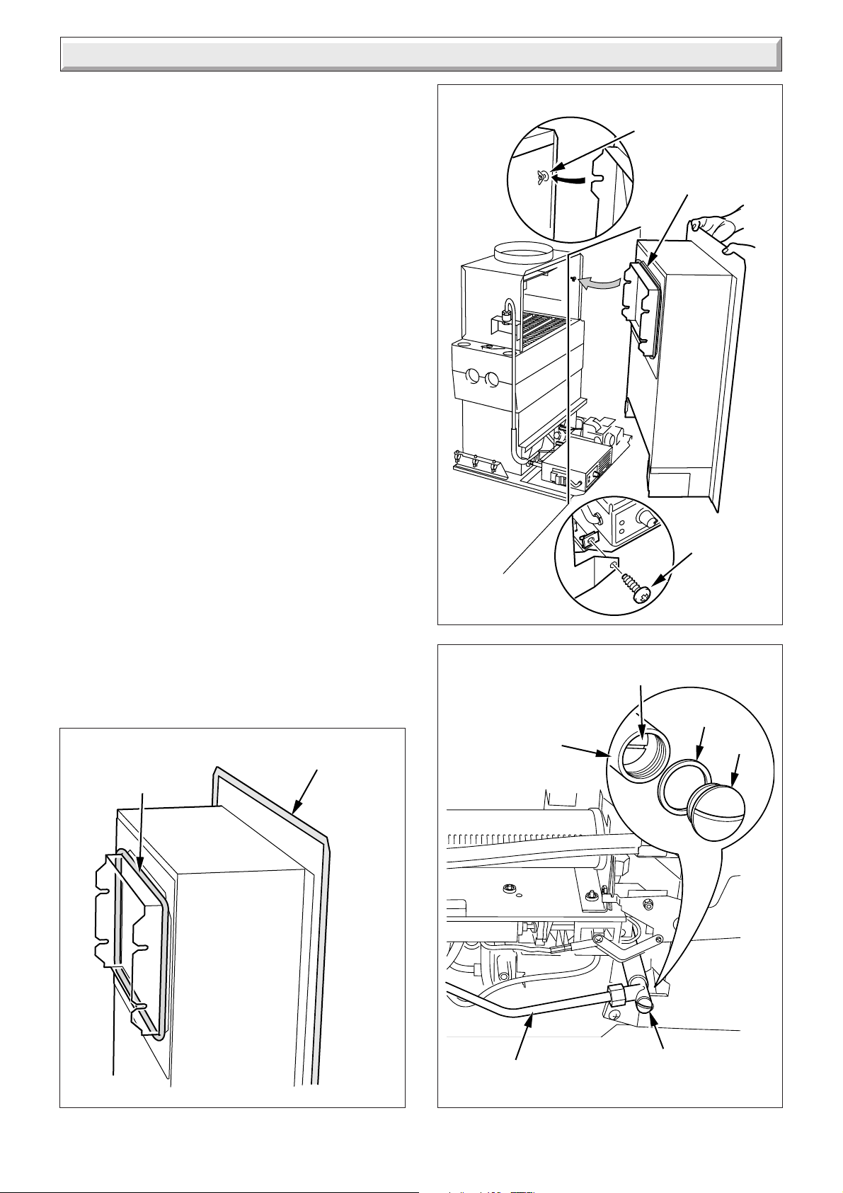
Fire Front Removal
This will be neccessary when servicing the back boiler unit.
Disconnect the union nut at the gas fire supply cock, see
diagram 3.3.
Remove the two securing screws, slacken the two wing nuts,
remove the fire front, see diagram 3.2.
IMPORTANT NOTE: Replace the fire front flue seal if neccessary.
Ensure the fire front flue seal is fitted before re-fitting the fire
front.
WING NUT
AND PLAIN
WASHER (2)
FIRE FRONT
FLUE SEAL
SECURING
SCREW (2)
10107
3.2 Gas Connection
Connect the gas supply tube, as diagram 3.3 tighten the nut at
the gas fire supply cock.
FIRE FRONT
FIRE FRONT
FLUE SEAL
WALL SEAL
10104
GAS FIRE
SUPPLY
COCK
RESTRICTOR
SCREW
WASHER
Diagram 3.2
10122
CAP
Diagram 3.1
11
GAS SUPPLY
TUBE
GAS FIRE
SUPPLY COCK
Diagram 3.3
221907B
Page 12

4 Lighting, Testing and Fitting of Internal Parts
Please ensure the “Benchmark” logbook (supplied with back
boiler unit) is completed and left with the user.
4.1 Lighting and Testing
The fire is fitted with a safety device.
The information in Section 1 must be observed.
Fit knob to slider control, see diagram 4.1.
The slider control will move up and down, as it does the locator
selects positions from off to ignition, see diagram 4.2.
It may be necessary to lubricate the slider plunger with a
suitable grease, i.e. Rocol tap grease, Spec. M23600, if the
slider is stiff.
Make sure that the gas control assembly is in the OFF position,
that is, the slider control is at the top, see diagram 4.2.
Fit the battery, see diagram 4.3.
Remove the pressure test nipple screw and fit a suitable
pressure gauge, see diagram 4.4.
Turn the gas supply on at the gas fire supply cock by removing
cap and turning restrictor screw anti-clockwise, see diagram
3.3.
To check for gas soundness, apply leak detection fluid to all
joints.
WARNING. Take care when doing the following check, as the
burner has a naked flame.
5897
CONTROL
KNOB
OFF POSITION
COKE SETTING
HEAT SETTING 3
HEAT SETTING 2
HEAT SETTING 1
Standard frame fitting
CONTROL
KNOB
SECURING
SCREW (2)
SLIDER CONTROL
CONTROL
KNOB
5922
SLIDER
IGNITION POSITION
LUBRICATE
HERE
Diagram 4.2
Wide frame fitting
221907B
SECURING
SCREW (2)
SLIDER CONTROL
Diagram 4.1
12
Page 13

4 Lighting, Testing and Fitting of Internal Parts
Slide the control knob all the way down to the ignition position,
against it’s stop, and hold, see diagram 4.2, clicking of the
ignition will be heard and the burner will light.
IMPORTANT If the burner does not light (instructions below)
within three seconds, return the knob to the OFF position, wait
for 10 seconds and repeat the following lighting operation.
1) Slide the control knob down to the “ignition position”, against
its stop and hold in position, see diagram 2, clicking of the
ignition will be heard and the burner will light.
2) Keep the knob in the ignition position for fifteen seconds after
the burner has lit. The ignition system will continue to operate,
indicated by the clicking at this time.
Note: Before releasing, ensure the control knob is against its
stop, to engage the flame supervision device.
Air may be present in the supply to the fire so that the initial
lighting operation may need to be repeated.
With the burner lit, check all joints for gas soundness, at all
control positions, in accordance with the current issue of BS6891.
Check that the gas pressure is as stated in the Data Section or
on the Data Label.
If there is any doubt about the gas rate, check at the meter,
having first turned off all other gas appliances and pilot lights.
The gas rate for this fire at heat setting 3 is 22.68ft
Check all heat settings, 1, 2, 3 and coke.
To turn the fire off, return the slider control to the top.
Remove the pressure gauge, refit the screw and make sure that
a gas tight seal is made.
Chatsworth only - fit the control shield, see diagram 4.5.
3
/h (0.8m3/h).
9461
BATTERY
Diagram 4.3
9465
4.2 Fire Frame
Remove the frame from the packaging.
Fit as shown in diagram 4.6
PRESSURE TEST
NIPPLE
Diagram 4.4
SECURING
SCREW (2)
10108
CONTROL SHIELD
Chatsworth only
13
Diagram 4.5
221907B
Page 14

4 Lighting, Testing and Fitting of Internal Parts
4.3 Fuelbed, Fret and Ashpit Fitting
For fuelbed fitting, see Instructions for Use
CAUTION. If the fuel effect supports and fuel effect pieces are
damaged, do not light the fire or further test until replacement
parts are fitted.
Fit the fret and ashpit cover as shown in diagram 4.7.
Take care not to damage the frame.
Chatsworth (black only). The brass coloured badge on the
appliance can be replaced with a black badge, which is supplied
in fret pack.
4.4 Heat Settings
Refer to diagram 4.2.
In the unlikely event of the burner going out whilst the fire is on,
return the slider to OFF. Wait three minutes before relighting.
If relighting for any other reason wait two minutes before doing
so.
4.5 Testing for Clearance of Products
The fire must be fitted with all its parts.
(a) WARNING. The fire front burner has an open flame.
(b) WARNING. Take care. The appliance will get hot during
testing.
(c) For the test you will need a smoke match and an extension.
(d) IN ALL CASES, if spillage continues after the specified test
periods steps must be taken to rectify the fault(s).
Possible causes include, flue obstruction, down draught or
restricted fresh air supply into the room.
If the problem cannot be put right the appliance must be
disconnected and expert advice sought.
TEST: WHERE NO FAN IS PRESENT
Close all outside doors, doors and windows in the room in which
the appliance is fitted.
Light the fire front only and run on heat setting 3. After 5 minutes
apply a spillage test as shown in diagram 4.8.
If spillage occurs, leave fire front alight for up to a further 10
minutes and repeat test. Turn the fire front off.
Next light the back boiler unit only. Run on maximum, after 10
minutes apply spillage test as shown diagram 4.8.
If spillage occurs, leave the boiler alight for up to a further 5
minutes and repeat tests.
Leave the boiler alight.
Now light the fire front. Run on heat setting 3, after 10 minutes
apply spillage tests as shown in diagram 4.9.
If spillage occurs leave the boiler and fire front alight for up to a
further 5 minutes and repeat the tests.
9468
FIRE FRAME
FIRE FRAME
SECURING SCREW (2)
Diagram 4.6
TEST: WHERE A FAN IS PRESENT
A fan means an extract fan or a fan for other open flued
appliances or a circulating fan for a warm air unit, (whether or
not gas fired). With the fan switched off carry out the appropriate
spillage test with all doors and windows closed, as above.
If the above spillage test is satisfactory proceed as follows:
Open all doors connecting the room containing the appliance
and the room in which the fan is fitted. Close all other doors and
windows in the premises.
If the fan is in the same room as the appliance, close all doors
and windows in that room. Switch the fan on and repeat the
spillage test as above.
In ALL cases, if spillage occurs the cause must be found and put
right before the fire is left.
IF THE FAULT CANNOT BE PUT RIGHT, THE FIRE MUST BE
DISCONNECTED AND EXPERT ADVICE SOUGHT.
221907B
14
Page 15

4 Lighting, Testing and Fitting of Internal Parts
ASHPIT
COVER
FRET
RETAINING
BRACKET
9457
15mm
35mm
FIRE FRONT
ONLY
BOILER
ONLY
15mm
60mm
90mm
90mm
9051
SMOKE
MATCH
AT END
OF
EMPLUME
TUBE
Diagram 4.8
9051
SMOKE
MATCH
AT END
OF
EMPLUME
TUBE
Chatsworth illustrated
FRET
Diagram 4.7
FIRE FRONT
AND BOILER
COMBINED
Diagram 4.9
15
221907B
Page 16

5 Instructions to User
Hand the Instructions for Use, Installation & Servicing to the
user and make sure that they are understood.
Refer to the Instructions for Use on how to light the fire.
Advise the customer that they should read their Users instructions
before operating the fire and always follow the advice in the
Section headed “Cleaning your Fire”.
Advise that any smell which may be apparent on initial lighting
is quite normal and it will quickly disappear.
Important. Advise that soft wall coverings, for example, blown
vinyl wallpaper, are easily affected by heat, they may, therefore,
scorch or become discoloured when close to a heating appliance.
This should be borne in mind when having a heating appliance
installed and when redecorating.
Advise that to ensure the continued efficient and safe operation
of the fire it is recommended that it is checked and serviced at
regular intervals. The frequency of servicing will depend upon
the particular installation and usage, but in general once a year
should be enough.
Advise that the chimney must be checked at least once a year
and any debris found removed.
Draw attention, if applicable, to the current issue of the Gas
Safety (Installation and Use) Regulations, 35, which imposes a
duty of care on all persons who let out any property containing
a gas appliance.
It is the Law that any servicing must be carried out by a
competent person.
Reminder - Leave these instructions and the “Benchmark”
logbook with the user.
6 Servicing
REMEMBER, When replacing a part on this appliance, use only
spare parts that you can be assured conform to the safety and
performance specification that we require. Do not use
reconditioned or copy parts that have not been clearly authorised
by Hepworth Heating Lt
6.1 Notes
To ensure the continued efficient and safe operation of the fire
it is recommended that it is checked and serviced at regular
intervals. The frequency of servicing will depend upon the
particular installation and usage, but in general once a year
should be enough.
It is the Law that any servicing is carried out by a competent
person.
Refer to Section 1.
Before starting make sure that the gas supply is turned off at the
gas fire supply cock, see diagram 6.1.
Make sure that the fire is cold before doing any servicing.
After servicing of parts always test for gas soundness with a
suitable leak detection fluid.
WARNING. Take care as the burner has a naked flame.
To test the gas control assembly apply leak detection fluid to all
joints, light the burner and check all joint for leakage at all
settings.
Carry out functional check of controls.
After removing or disconnecting any pipework always make
sure that it is refitted correctly and does not interfere with the
fitting of the fire.
Unless stated otherwise all parts are replaced in the reverse
order to removal.
6.2 Fret and Ashpit Cover
Remove fret and ashpit cover, see diagram 4.7.
Take care not to damage the frame.
Turn the gas supply off at the fire front service cock, see
diagram 6.1.
6.3 Fuel Bed Supports and Fuel Effect Pieces
Following steps 1 to 8 in reverse order, remove the fuel effect
pieces and fuel effect supports, see diagram 6 in Instructions for
Use section.
Care should be taken as they become fragile with use.
Clean the fuel effect pieces and the fuel effect supports with a
soft brush.
IMPORTANT: A VACUUM CLEANER MUST NOT BE USED
ON FUEL EFFECT PIECES OR FUEL EFFECT SUPPORTS.
With the fuel effect pieces and fuel effect supports removed, the
base of the appliance may be cleaned with a vacuum cleaner.
NOTE: The importance of positioning the fuel effect pieces
correctly cannot be overemphasised if sooting is to be avoided.
The flame effect may also be impaired and the life of the fuel
effect pieces reduced if assembly directions are not followed,
see section 4.3.
221907B
16
Page 17

6 Servicing
6.4 Burner and Injector
The burner can be cleaned, using a suitable soft brush or
vacuum cleaner.
Do not use a brush with wire bristles.
Disconnect the gas supply at the fire front gas service cock.
Remove the frame and fire front from the wall, refer to relevant
parts of Sections 4.3, 4.2, 3.2 and 3.1.
With the fire front removed lay it on its back. Remove the three
wires from the spark generator, see diagram 8.1.
Remove the shouldered securing screw, the burner securing
screws pull out the burner assembly, see diagram 6.1.
Disconnect the gas supply pipe union nut from the injector and
slacken the connection at the gas control valve, pull the pipe off
the injector, see diagram 6.2.
Remove the injector.
Do not clean the hole with a wire or sharp instrument.
6.5 Flue Blockage Safety Device
Refer to Section 1.1.
When cleaning make sure that all the holes in the safety device
are clear of dust and lint.
If damaged replace the safety device as Section 8.10.
GAS CONTROL VALVE
CONNECTION
BURNER
SECURING
SCREW (2)
BURNER
ASSEMBLY
6224
GAS SUPPLY
PIPE UNION
NUT
BURNER ASSEMBLY
SECURING SCREW
BURNER
ASSEMBLY
GAS FIRE
SUPPLY COCK
INJECTOR
SHOULDERED
SECURING SCREW
Diagram 6.2
9470
BURNER ASSEMBLY
SECURING SCREW
17
Diagram 6.1
221907B
Page 18

6 Servicing
EARTH POST
ELECTRODE
Make sure this hole is
clear of dust and lint
SPARK GAP
3 + 1 or - 0.5
THERMOCOUPLE
Diagram 6.3
SLIDE UNDER BURNER
SUPPORT TAB
6.6 Electrode
5924
Ensure that the electrode is in line with the earth post and that
the spark gap is as shown in diagram 6.3.
If damaged replace the safety device as Section 8.10.
6.7 Thermocouple
Inspect the thermocouple for wear and damage, clean with a
soft brush, see diagram 6.3.
If damaged replace the safety device as Section 8.10.
When replacing the burner assembly, refer to diagram 6.4
(Locating burner support tabs).
6.8 Ignition Lead
Inspect the ignition lead for wear and damage, replace if
necessary.
NOTE: When replacing the burner refer to diagram 6.4 (Locating
the burner support tabs).
10123
BURNER
BURNER ASSEMBLY
(Secure with previously
removed securing screws)
BURNER
221907B
Diagram 6.4
18
Page 19

7 Fault Finding
7.1 Fire Ignition
Refer to Fire Ignition Sequence of Operations, see diagram 7.1.
7.2 Safety Device
If the fire shuts down for no apparent reason the flue/chimney
and the air inlets into the room must be checked.
Check that gas supply is available, free of obstructions and purged of air. Ensure that linkage operates spindle
on gas valve. Ensure electrode is not cracked, the spark gap is correct and the ignition lead is in good condition.
Press control lever
down to ignition
position
Are sparks visible
at electrode
YES
Does pilot and burner
ignite at low rate
YES
Hold control lever
in ignition position
for several seconds.
Move control lever
to position 1.
Do ignition sparks
stop?
YES
Does fire remain
alight at low rate?
YES
NO
NO
NO
NO
Check battery voltage
and if fitted correctly.
If voltage is less than
7.5V, replace.
Press control lever
to ignition position.
Are sparks visible?
YES
Faulty gas
control valve.
Replace
Faulty microswitch 1
Replace
Hold control lever in ignition position.
If after several seconds the milli voltage is not
greater than 6mV. Replace faulty thermocouple
Any problems found must be put right, before the fire is used
again.
Also, check for dust and lint around the holes in the safety
device.
IN ALL cases the room must be ventilated before attempting to
relight the fire.
The safety device must not be bypassed or put out of action.
Disconnect black
NO
YES
wires from spark
generator.
Depress control
lever to ignition
position. Check
continuity of
micro-switch,
is there continuity?
NO
Faulty ignition.
Replace microswitch 2
6015
Move control lever
to position 2.
Does rate increase?
YES
Move control lever to
position 3.
Does rate increase?
YES
Move control lever to
COKE position.
Does flame picture
change to blue from yellow?
(when fire is hot)
YES
Move control lever to
off position. Does fire
go out?
YES
NO
NO
NO
NO
Faulty gas control
valve. Replace
Faulty gas control
valve. Replace
Check that aeration
plate on side of burner
NO
is moving when control
lever moves from coal
to coke position.
If faulty Replace
Faulty off
Replace microswitch 1.
19
Sequence of
operation correct
Diagram 7.1
221907B
Page 20

8 Replacement of Parts
For the replacement of parts it is advisable in most cases to
remove the fire front from the back boiler unit. Refer to relevant
parts of Sections 4.3, 4.2, 3.2 and 3.1 for removal.
Notes:
Refer to Section 1.
Make sure that the fire front is cold before replacing any parts.
Replacement of parts must be done by a competent person.
Isolate the gas supply to the fire front, see diagram 6.1.
After replacing or disconnecting any gas carrying part, always
test for gas soundness, using a suitable leak detection fluid and
carry out functional check of controls.
To test the gas control assembly apply leak detection fluid to all
joints, light the burner and check all the joints for leakage at all
tap settings.
After removing or disconnecting any pipework always make
sure that it is refitted correctly and does not interfere with the
fitting of the fire front.
Unless stated otherwise reassembly of all parts is in the reverse
order to removal.
8.1 Fret and Ashpit Cover
Remove the fret and ashpit cover, see diagram 4.7.
Take care not to damage the frame.
Turn the gas supply off at the fire front gas service cock, see
diagram 6.1.
8.6 Spark Generator
Remove the fire front from the back boiler unit.
Carefully lay the fire front on its back.
Disconnect the ignition lead and black cables, remove the
securing screws, see diagram 8.1.
When reconnecting, the polarity of the connection from the
generator to the microswitch is not important.
8.7 Battery
Remove the fret see diagram 4.7.
Take care not to damage the frame.
The battery is 9V and we recommend that it is of the alkaline
type, bought locally.
When fitting make sure that it is connected as shown in diagram
4.3.
8.2 Fuel effect pieces and fuel bed supports
Refer to Section 4.3 and follow steps 8 to 1 to remove the fuel
effect pieces and fuel bed supports, see diagram 6, in Instructions
for Use.
8.3 Frame
To remove refer to diagram 4.6.
8.4 Burner Assembly
Remove the fire front from the back boiler unit.
Follow the instructions in Section 6.4 to remove the burner
assembly.
To remove the burner disconnect the injector in Section 6.4,
then remove the burner securing screws, this will release the
burner.
8.5 Injector
Follow the relevant instructions in Section 6.4 to remove the
injector.
9V
BATTERY
SECURING
SCREW
10109
221907B
20
BLACK
CABLES
SPARK
GENERATOR
IGNITION LEAD
Diagram 8.1
Page 21

8 Replacement of Parts
8.8 Microswitch 1 and 2
Remove the fire front from the back boiler unit.
Follow instructions in Section 6.4 to remove the burner assembly.
To remove Microswitch 1, see diagram 8.2.
Remove the securing screws, nuts and electrical leads.
To remove Microswitch 2, see diagrams 8.1 and 8.2.
Remove the spark generator, diagram 8.1.
Remove the gas tap fitting block, diagram 8.2.
Remove the three securing screws to release the gas control
valve, diagram 8.2.
Remove the circlip, diagram 8.2.
Disconnect the black cables from the microswitch, diagram 8.2.
Remove the microswitch, diagram 8.2.
When re-assembling make sure to refit the spacers between
the gas control and burner assembly.
BLACK CABLES
MICROSWITCH 1
SECURING
SCREW (2)
MICROSWITCH 2
Must be fitted as shown
SECURING
SCREW
WASHER (2)
BLACK CABLES
NUT (2)
SCREWS (3)
ELECTRICAL
LEADS
WHITE
CABLES
6246
GAS TAP
FITTING
BLOCK
SECURING
SCREW
GAS TAP
SPINDLE
CIRCLIP
21
SPACERS (3)
Diagram 8.2
221907B
Page 22

8 Replacement of Parts
UNION NUTS
SECURING
SCREW (3)
THERMOCOUPLE
NUT
SPACERS (3)
8.9 Gas Control Valve
Remove the fire front from the back boiler unit.
Follow instructions in Section 6.4 to remove the burner assembly
Remove the gas control valve, disconnecting the union nuts,
thermocouple nut, gas tap fitting block, electrical leads and gas
control valve securing screws, this will release the gas control
valve, see diagram 8.3.
Remove the microswitch 2, see relevant parts of Section 8.8.
When re-assembling make sure to refit the spacers between
the gas control valve and burner assembly.
SECURING
SCREW
GAS CONTROL
VALVE
THERMOCOUPLE
NUT
ELECTRICAL
LEADS
SECURING
SCREW
GAS TAP
FITTING
BLOCK
Diagram 8.3
ELECTRICAL
CONNECTIONS
PILOT PIPE
UNION NUT
IGNITION
LEAD
6247
6222
8.10 Safety Device
Refer to Section 1.
Remove the fire front from the back boiler unit.
Follow instructions in Section 6.4 to remove the burner assembly
Refer to diagram 8.4, disconnect:
-the ignition lead
-the pilot pipe union at the safety device
-the thermocouple nut at the gas control valve
-the electrical connections
-the safety device bracket
-the safety device
8.11 Ignition Lead
Follow relevant parts of section 8.6.
Disconnect the ignition lead at the electrode and spark generator,
refer to diagrams 8.1 and 8.4.
CAPILLARY
SAFETY
DEVICE
SILICONE
COVER
SAFETY
DEVICE
BRACKET
SECURING
SCREW (2)
SECURING
SCREW (2)
Diagram 8.4
221907B
22
Page 23

9 Spare Parts
When spare parts are required use only genuine Glow-worm
parts and buy them from a recognised supplier.
Use only the fuel effect approved for this fire front.
Do not use more fuel effect pieces than shown.
Key No Part No Description G.C. No.
1 210269 Rear support E04764
2 210268 Middle support E04765
3 210272 Fuel effect pieces (small) E04767
4 210273 Fuel effect pieces (large) E04769
5 210270 Side support L/H E04770
6 210271 Side support R/H E04768
7 210267 Front support E11725
8 202179 Spark Generator 378351
9 230502 Gas control valve assy ********
10 205739 Injector - Bray Cat 82-500 E04735
11 203443 Flue blockage safety device - SIT Ref: 9409 E04758
12 202275 Microswitch 1 E04761
13 800886 Microswitch 2 E04747
14 WX5500 Ignition lead 278467
15 209310P Silver Badge (Black Chatsworth) E04772
15 209311P Brass Badge (Black Chatsworth) E04773
16 800895 Gas tap spindle Circlip E04748
17 212308 Fire Front Flue Seal ********
Please quote the name of the fire front “Dovedale” or
“Chatsworth”.
If ordering from British Gas also quote the GC numberof the fire
from the data label and the GC number of the spare part, from
the list.
1
17
5918
8
2
16
3
10
15
9
11
12
13
4
6
5
7
23
14
Diagram 9.1
221907B
Page 24

Because of our constant endeavour for improvement details may vary slightly from those in the instructions.
221907B
24
 Loading...