

Page 1
Clearly Solar
Solar Thermal Flat Plate Collector
Installation Instructions
www.glow-worm.co.uk
1
Vertical In-roof
mounting
15°- 22° & 22°- 75°
SRV 2.3
Page 2

Guarantee Registration
These Clearly Solar Flat Plate collectors come with a comprehensive manufacturer’s guarantee.
Details of the guarantee, and the terms and conditions that apply can be found on the Guarantee
registration card. We recommend you complete and return this as soon as possible.
Customer Service:
01773 596510
Technical Helpline:
01773 828300
General and Sales enquiries:
Tel. 01773 824639
Fax: 01773 820569
To register your Glow-worm appliance call:
0800 0732142
Benchmark places responsibilities on both manufacturers and installers. The purpose is to ensure that customers are provided
with the correct equipment for their needs, that it is installed, commissioned and serviced in accordance with the manufacturer’s
instructions by competent persons and that it meets the requirements of the appropriate Building Regulations. The Benchmark
Checklist can be used to demonstrate compliance with Building Regulations and should be provided to the customer for future
reference.
Installers are required to carry out installation, commissioning and servicing work in accordance with the Benchmark Code of
Practice which is available from the Heating and Hotwater Industry Council who manage and promote the Scheme.
Visit www.centralheating.co.uk for more information.
2
Page 3

These instructions must be handed to the user on completion of the installation.
CONTENTS DESCRIPTION SECTION PAGE
Warnings 4
GENERAL
INFORMATION
Important Information 4
Statutory Requirements 5
TECHNICAL
SPECIFICATION
ROOF MOUNTING
Technical Specication 1 6
Technical Data 2 7
Solar Collector and Hydraulic
Connection Arrangement 3 8
Hydraulic Connection Kits 4 9
Single Collector Flashing
Kit - 22-75º 5 10
Two Collector Flashing
Kit - 22-75º 6 16
One Collector Extension Kit - 22-75º 7 23
Two Collector Flashing
Kit - 15-22º 8 30
Three Collector Flashing
Kit - 15-22º 9 37
3
Page 4

WARNINGS
Metal Parts
This collector contains metal parts (components) and care should be taken when handling,
with particular regard to edges.
Risk of death from falls and falling objects
Observe the national regulations for working at heights.
Danger of burning and scalding
The collectors can reach 200°C.
Do not remove the factory tted sun protective lm until the commissioning is to be completed.
Sealed Components
Under no circumstances must the user interfere with or adjust sealed parts.
Important Information
General
These instructions must be handed to the user on completion
of the installation.
This installation instruction applies exclusively to the mounting
of the solar collector.
The solar collector is one component in a solar system and
it is recommended that you read all other component(s)
literature prior to installation.
We accept no liability for any damage caused by failure to
observe these instructions.
Control of Substances Hazardous to Health
Under Section 6 of The Health and Safety at Work Act
1974, we are required to provide information on substances
hazardous to health.
The adhesives and sealants used in this appliance are cured
and give no known hazard in this state.
Solar uid
For solar uid safety data, please refer to Clearly Solar
System Hydraulics literature.
Manual Handling
With regards to the “Manual Handling Operations, 1992
Regulations”, this product exceeds the recommended weight
for a one man lift.
Recommend 2 person lift. Ensure safe lifting techniques are
used – keep back straight – bend using legs. Keep load as
close to body as possible. Ensure co-ordinated movements
during lift. Clear the route before attempting the lift. If
removing from truck straddle the load and tilt forwards to
facilitate secure grip. Do not twist – reposition feet instead.
Take care to avoid trip hazards, slippery or wet surfaces and
when climbing steps or ladders. Always use assistance if
required.
Installation of the solar collector will require a risk
assessment.
Testing and Certication
This solar collector is tested and certicated for safety and
performance. It is, therefore, important that no alteration is
made, without permission, in writing, by Glow-worm.
Any alteration not approved by Glow-worm, could invalidate
the certication, warranty and may also infringe the current
issue of the statutory requirements.
CE Mark
The CE mark on the solar collector indicates that it complies
with the basic requirements of the applicable directives as
stated on the data label.
Damage from lightning
If the installation height is more than 20m, electro-conductive
components must be connected to a lightning protection
device.
Frost Protection
Under no circumstances should water be in the solar collector
if there is a danger of frost.
After pressurisation and ushing, the solar collector(s) may
contain water residue.
Water remaining in the solar circuit will dilute the uid.
Immediately ll the solar system with solar uid. Check the
uid concentration with a frost protection tester.
4
Page 5

Statutory Requirements
IMPORTANT
Where no British Standards exists, materials and equipment
should be t for their purpose and of suitable quality and
workmanship.
The installation of this solar collector must be carried out by
a competent person in accordance the rules in force in the
countries of destination.
Manufacturer’s instructions must not be taken as overriding
statutory requirements.
Statutory Requirements
In GB, the installation of the solar collector must comply
with the requirements of the current issue of the following
regulations:
The manufacturer’s instructions supplied.
The appropriate Buildings Regulations either The Building
Regulations, The Building Regulations (Scotland),The
Building Regulations (Northern Ireland).
Working at Heights Regulations 2005.
Lightning protection requirements.
Equipotential bonding of electrical installations.
The Health and Safety at Work Act
Control of Substances Hazardous to Health (COSHH).
The Current I.E.E. Wiring Regulations.
The Water Supply (water ttings) Regulations 1999 or the
Water Byelaws 2000 (Scotland).
Where no specic instructions are given, reference should be
made to the relevant British Standard Code of Practice.
Regulations for the prevention of accidents
At all times follow the national regulations on working at
heights.
Make sure there is suitable safety equipment such as
scaffolding or protective walls to prevent falling from roofs.
Fall protection systems such as the Glow-worm fall protection
system (item no. 0020054985) also has a fall arresting device
if the roof scaffold and protective roof wall are inappropriate
for the specic task.
Only use tools and equipment such as lifting gear or ladders
in accordance with the lifting regulations.
Cordon off areas below the working area sufciently to protect
people from falling objects.
Mark the working area, for example with warning signs as
described by the national regulations.
5
Page 6

1 Technical Specication
Design Description
The Clearly Solar collector, collects the available solar
radiation and transfers the heat through the solar uid to be
utilised by the system.
It has been designed to compliment the complete range of
Glow-worm solar system components.
The kits are suitable for roof pitches between 15°- 75°, please
choose from the table below.
The solar thermal at plate collector includes a saltwater-
resistant aluminium frame as well as a copper surface
absorber with a high selective coating.
The at plate collector has a CFC-free, standstill temperature-
resistant mineral wool insulation for long-life and excellent
heat insulation.
Hydraulic connections are push-t with double ‘O’ ring
sealing. The sensor sleeve is integrated into the hydraulic ow
connection.
The following kits are available and dependant upon the
number of collectors, the quantities required are listed in the
following tables and illustrated in the appropriate sections:-
15-22° roof angle
Number of collectors 2 3
Two panel collector flashing kit - Section 8
Part number 0020059886
Three panel collector flashing kit - Section 9
Part number 0020059888
Easy fit hydraulic connection set - Section 4
Part number 0020065271
Easy fit hydraulic extension set - Section 4
Part number 0020059909
1 -
- 1
1 1
1 2
22-75° roof angle
Number of collectors 1 2 3 4 5 6 7 8 9 10 11 12
Single panel collector flashing kit
- Section 5.
Part number 0020060316
Two panel collector flashing kit
- Section 6.
Part number 0020060318
One panel extension kit - Section 7
Part number 0020060327
Easy fit hydraulic connection set
- Section 4.
Part number 0020065271
Easy fit hydraulic extension set
- Section 4.
Part number 0020059909
1 - - - - - - - - - - -
- 1 1 1 1 1 1 1 1 1 1 1
- - 1 2 3 4 5 6 7 8 9 10
1
- 1 2 3 4 5 6 7 8 9 10 11
6
Page 7
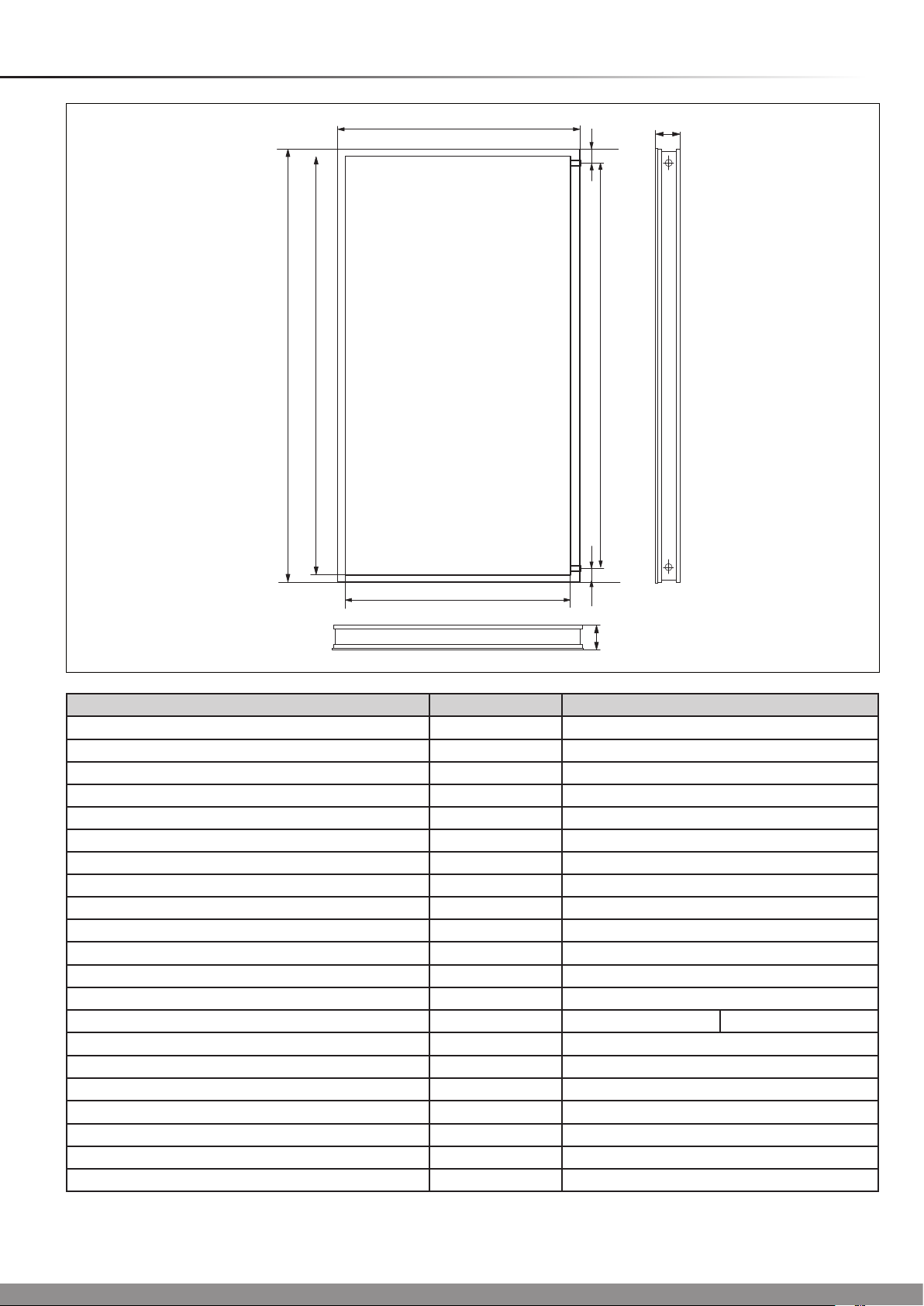
2 Technical Data
2033
1978
1233
79
80
14922
1875
1178
79
80
Diagram 2.1Vertical Collector
Appliance designation Unit. Clearly Solar
Absorber type Serpentine
Gross area m
Aperture surface area m
Absorber surface area m
2
2
2
Absorber Aluminium (vacuum coated) 0.5 x 1178 x 1978
Dimensions (L x W x H) mm 2033 x 1233 x 80
Weight (Dry) kg 38
Fluid content l 1.85
Copper pipe connection, at-face Ø mm G 3/4" (DN16)
Insulation thickness mm 40
Max. operating pressure bar 10
Glass type Solar safety glass (prismatic structure)
Glass covering mm 3.2 (thickness) x 1233 x 2033
Coating High selective (blue) α = 95% ε = 5%
Transmission %
2
Back wall insulation mm, W/m
K, kg/m340 λ = 0.035 ρ = 55
Stagnation temperature °C 210
Efciency η
0
% 80
Heat capacity Ws/m•K 5014
Heat loss factor k
Heat loss factor k
1
2
W/m2•K 3.7
W/m2•K
2
2.51
2.35
2.33
t = 91
0,012
7
Page 8
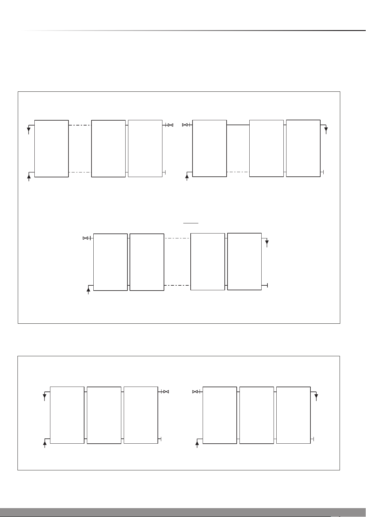
3 Solar Collector and Hydraulic Connection Arrangement
Solar Collector
The recommended collector arrangements are shown below.
Roof Pitch 220-75
0
1-5 Collectors
THE HYDRAULIC FLOW CAN BE TOP AND BOTTOM OR DIAGONAL
1 4 5...
TOP & BOTTOM DIAGONAL
6 and up to 12 max Collectors
THE HYDRAULIC FLOW MUST BE DIAGONAL
Hydraulic Connections
It is recommended that the hydraulic connections should be
made as shown below.
15025
1 4 5...
Roof Pitch 150-22
15139
1 2 3
1
0
2
...
DIAGONAL
11
12
1-3 max. Collectors
THE HYDRAULIC FLOW CAN BE TOP AND BOTTOM OR DIAGONAL
1 2 3
14915
Diagram 3.1
15140
TOP & BOTTOM DIAGONAL
8
Diagram 3.2
Page 9
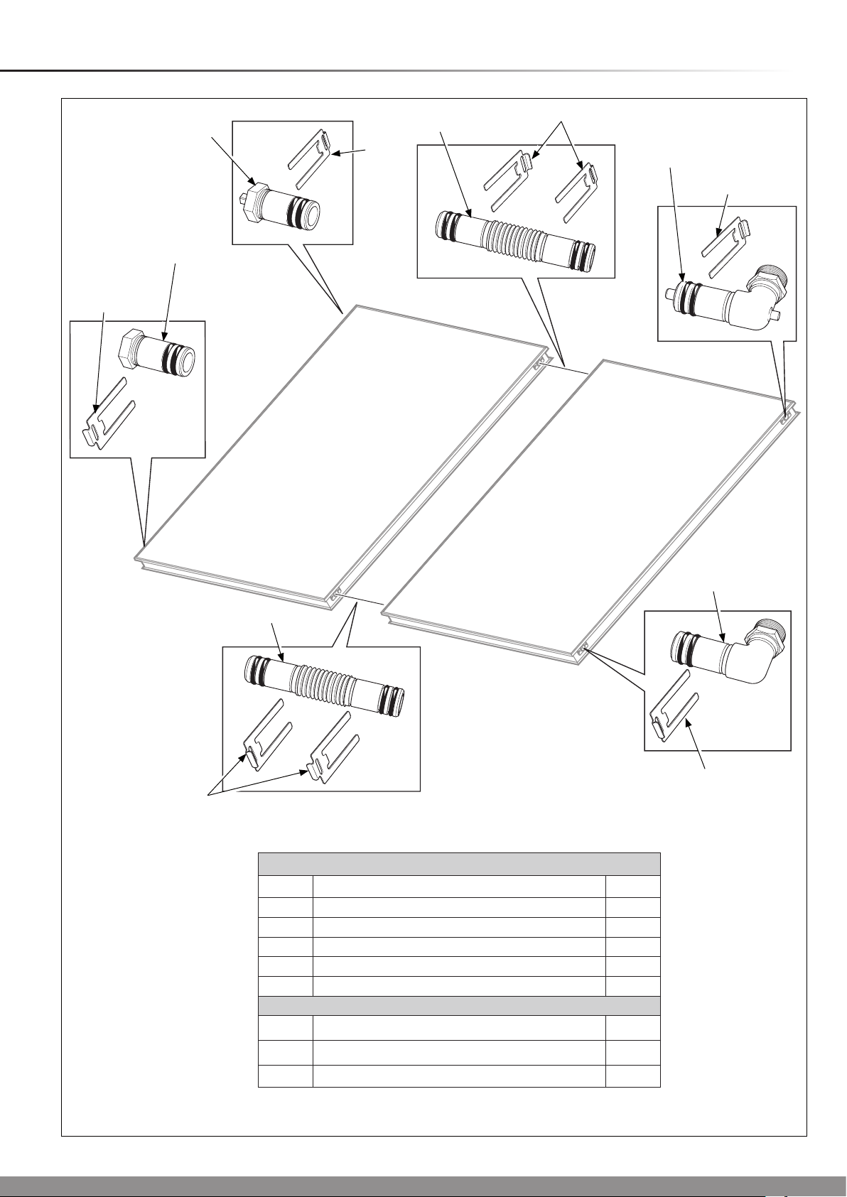
4 Hydraulic Connection Kits
5
1
6
14972
2
1
4
1
7
3
6
1
7
Easy fit hydraulic connection set - Part No. 0020065271
Part Description Qty.
1 Securing clip 4
2 Flow connection 1
3 Return (inlet) 1
4 Lower plug 1
5 Upper plug (with ventilation) 1
Easy fit hydraulic extension set - Part No. 0020059909
Part Description Qty.
6 Pipe coupling 2
7 Securing clip 4
9
Diagram 4.1
Page 10

TX25
SCREW
No.1
SCREW
No.2
SCREW
No.3
SCREW
No.4
5 Single Collector Flashing Kit - 220 - 75
2
1
12
7
4
11
3
0
15021
8
5
10
6
9
1 collector in-roof kit for roof angle 22-75° - Kit No. 0020060316
Part Description Qty.
1 Tile bar 1
2 Ridge plate 1
3 Right side section 1
4 Left side section 1
5 Profile end 2
6 Lower flashing 1
7 Roof batten 3
8 Inner clamp 9
Screws No.1
9
10 External clamp 10
11 Support plate 2
12 Support board 1
Screws No.2
Screws No.3
Screws No.4
16
15
7
6
10
Diagram 5.1
Page 11
5 Single Collector Flashing Kit - 220 - 75
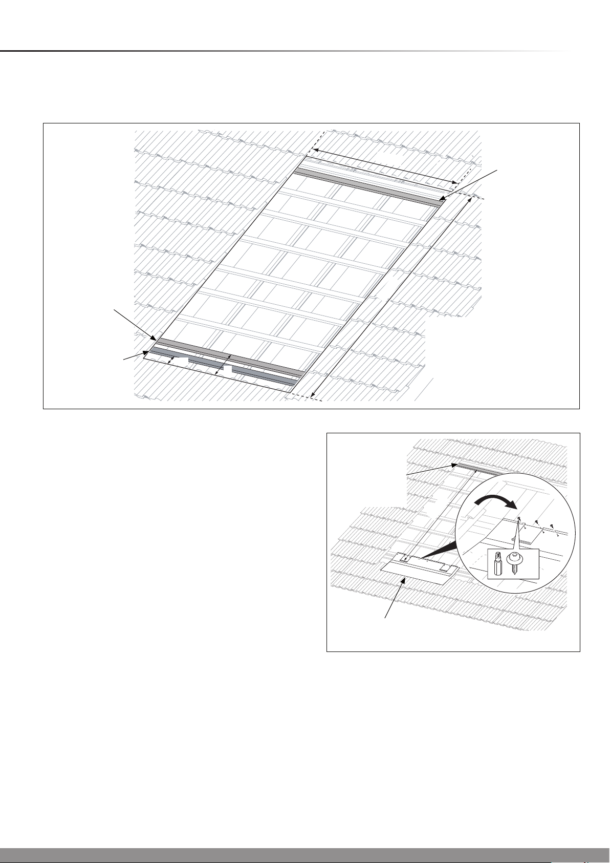
Roof Requirements
Refer to the diagram and table below and conrm the roof
requirements before installation.
0
The bottom
flashing is fixed
to this (original)
batten
Additional
batten to
support the
150
A
collector
IMPORTANT
● Do not remove the protection lm until the system is to be
commissioned.
● With due regard to the complete weight of the solar
collector system, (refer to technical data) ensure the
roof rafters and battens are in good condition and have
sufcient load carrying capacity and the battens are
secure.
● If you are using the existing roof battens for xing, ensure
that they are secured at each rafter.
2080
2725
Additional
batten for
securing the
top flashing
fixings
15197
TOP
BATTEN
Distance ‘A’ must
be between 280mm
and 309mm. Use an
additional batten if
required
Diagram 5.2
15022
2380
5.1 Installation
NOTE: Ensure adequate provision has been made for the
ow and return pipes to enter/exit the roof space, dependant
on their location. The preferred hydraulic scheme will
determine their location, refer to Section 3.
Refer to diagram 5.1 and check the contents of the kits prior
to commencing work on the roof.
Based on the dimensions, above, remove the roof covering.
Fix the lower ashing support batten, see diagram 5.2.
Position the lower ashing onto the roof batten and secure
with the six screws (no.1) and Torx bit supplied, see diagram
5.3.
No.1
LOWER FLASHING
Diagram 5.3
11
Page 12
5 Single Collector Flashing Kit - 220 - 75
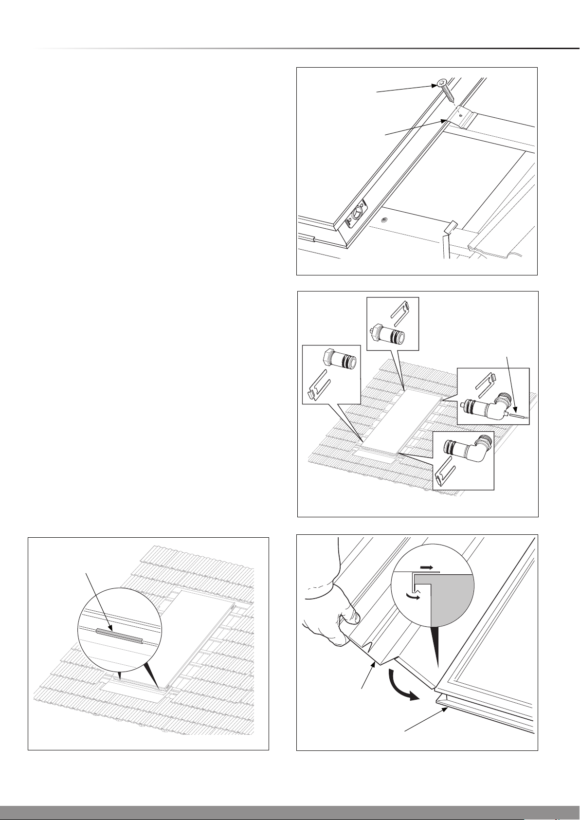
Position the collector, protective side uppermost into the
location channel as shown in diagram 5.4.
NOTE: The design is symmetrical and does not have a top or
bottom.
Secure the collector with the clamps and screws provided, see
diagram 5.5.
With regards to the hydraulic system you have chosen, insert
and secure the hydraulic connections, see diagram 5.6.
Insert the collector sensor into the appropriate elbow (ow,
top), see diagram 5.6. The collector sensor is packed with the
Fluropro controller, part no. 0020054960.
Mount the plug with the bleed valve in the opposite top
position.
SCREW
(No.3)
CLAMP
0
14974
Connect the collector to the system circuit.
Ensure that all of the following steps have been performed:-
- All the connections have been xed with securing clips.
- All hydraulic connections laid properly.
- The collector sensor has been connected.
- The collector is connected to a lightning protection device.
- A pressure test.
- All insulation is intact.
NOTE: After initial commissioning and according to the season,
high outside temperature oscillations can cause condensation
in the collector, this is normal.
Fit the side sections to the collector frame, ensure that it is
pushed into place on the collector edge, see diagram 5.7.
Diagram 5.5
15023
COLLECTOR
SENSOR
Diagram 5.6
LOCATION
CHANNEL
Diagram 5.4
15026
12
14979
SIDE
SECTION
COLLECTOR
Diagram 5.7
Page 13
5 Single Collector Flashing Kit - 220 - 75
0
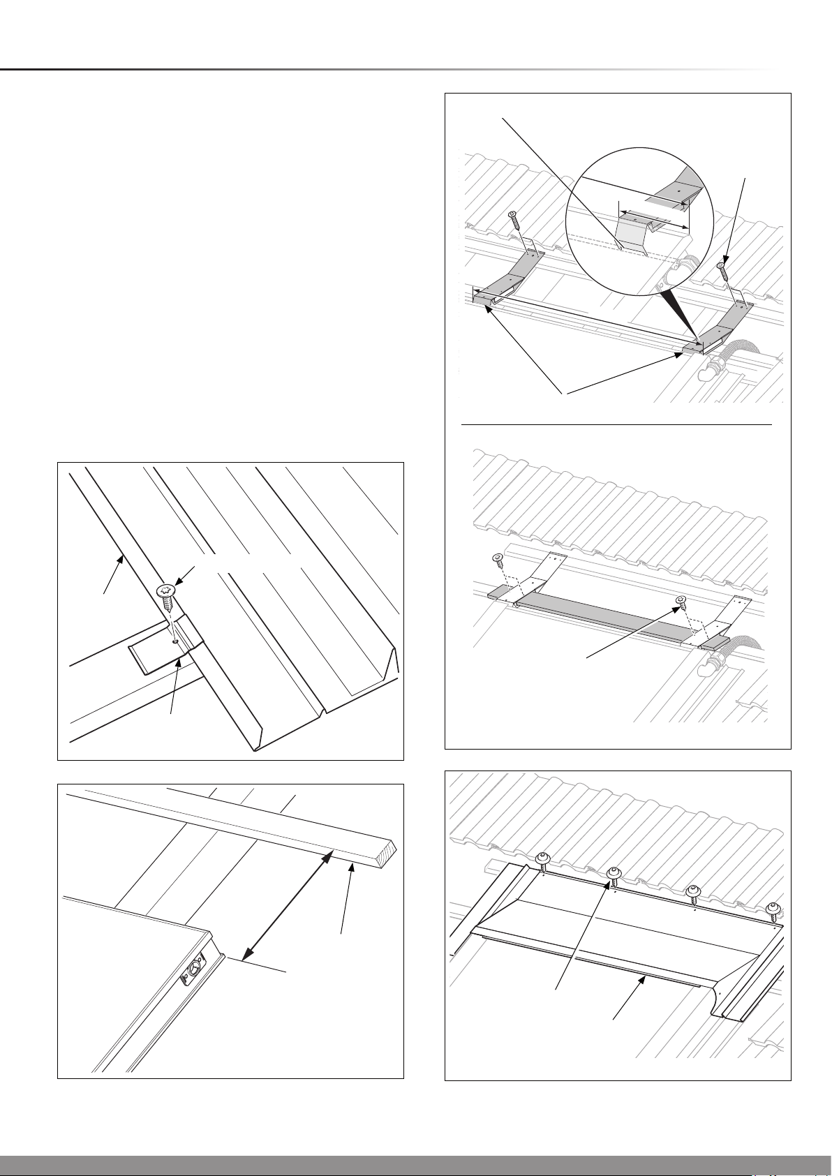
Secure the side sections to the roof battens with the supplied
clamps, screws (No. 2) and Torx bit supplied, see diagram
5.8.
5.2 Support plates/board
Fix the top batten into position as shown in diagram 5.9.
Mount the support plates above the collector and make sure
that the support plates are on the collector frame slot, see
diagram 5.10.
Fix the support plates to the top roof batten with two screws
(No.3) using the supplied Torx bit.
Slide the board through the support plates.
Fix the board to the support plates with two screws (No. 2)
using the supplied Torx bit, see diagram 5.10.
Slide the ridge plate on the support plates, see diagram 5.12.
Make sure that the ridge plates are above the side sections
and engaged in the corresponding rail (A).
Fix the ridge plate to the roof battens with the screws (No. 1)
using the supplied Torx bit, see diagram 5.11.
14978
COLLECTOR FRAME
SLOT
SUPPORT PLATES
1066
1066
SCREWS
(No.3)
max 150
15027 15029
SIDE
SECTION
CLAMP
SCREW (No.2)
SCREWS
(No.2)
Diagram 5.10
Diagram 5.8
15030
15308
350mm
TOP
BATTEN
Diagram 5.9
SCREWS (No.1)
RIDGE
PLATE
Diagram 5.11
13
Page 14
5 Single Collector Flashing Kit - 220 - 75
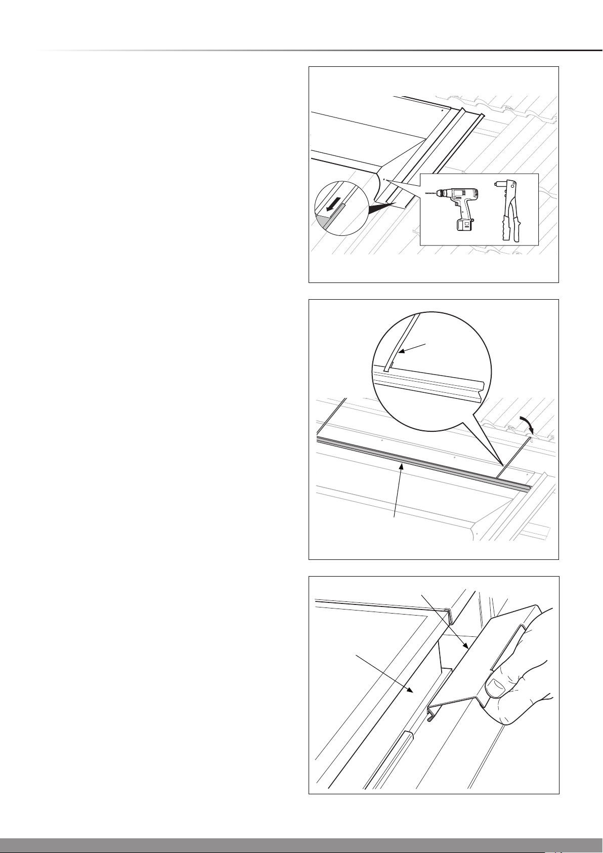
5.3 Riveting the frame
Drill a 4.5 mm diameter hole through the ridge plates on the
marks on the left and right hand respectively, see diagram
5.12.
Rivet the ridge plate to the side section.
5.4 Tile Bars
Place the tile bars on the ridge plates.
Bend the metal bands and hook the tile bars to the roof batten
from the top, see diagram 5.13.
5.5 Covering the prole ends
Cover the side prole ends and the collector joints with the
prole end pieces, see diagram 5.1 for prole end location.
Fit the prole end pieces to the bottom of the collector edge
and then tilt them up, until they lock in the upper collector
edge, see diagram 5.14.
0
15028
4,5
A
Diagram 5.12
TILE BAR
STRAP
TILE BAR
PROFILE END PIECE
14964
Diagram 5.13
14981
14
COLLECTOR
EDGE
Diagram 5.14
Page 15

5 Single Collector Flashing Kit - 220 - 75
5.6 Flexible ashing
NOTE: Ensure that the adhesive surface is dry and free from
dust and grease.
Remove the protection lm from the adhesive surface of the
exible ashing.
Contour the exible protection to the tile shape, see diagram
5.15.
5.7 Sealing strip
Attach the self adhesive sealing strip on the side sections of
the collector frame as shown in diagram 5.16 and also on the
ridge plates, see diagram 5.17.
If necessary carefully cut the sealing strip with a trimming knife.
0
14966
FLEXIBLE
FLASHING
OVERLAP
Diagram 5.15
SEALING
STRIP
14968
Diagram 5.16
14968
SEALING STRIP
15
Diagram 5.17
Page 16

TX25
SCREW
No.1
SCREW
No.2
SCREW
No.3
SCREW
No.4
SCREW
No.5
14
6 Two Collector Flashing Kit - 220 - 75
15
2
0
15017
1
10
9
3
16
4
11
5
6
13
8
7
12
2 collector in-roof kit for roof angle 22-75° - Kit No.
0020060318
Part Description Qty.
1 Tile bar 2
2 Left ridge plate 1
3 Right ridge plate 1
4 Left side section 1
5 Right side section 1
6 Profile end 3
7 Right lower flashing 1
8 Left lower flashing 1
9 Intermediate plate 1
10 Roof batten 3
11 Inner clamp 9
Part Description Qty.
Screws No.1
12
13 External clamp 10
14 Support board 1
15 Upper ridge plate coupling 1
16 Support plate 3
Screws No.2
Screws No.3
Screws No.4
Screws No.5
28
17
10
10
3
16
Diagram 6.1
Page 17

6 Two Collector Flashing Kit - 220 - 75
Roof Requirements
Refer to the diagram and table below and conrm the roof
requirements before installation.
0
The bottom
flashing is fixed
to this (original)
batten
Additional
batten to
support the
collector
Distance ‘A’ must
150
A
be between 280mm
and 309mm. Use an
additional batten if
required
IMPORTANT
● Do not remove the protection lm until the system is to be
commissioned.
● With due regard to the complete weight of the solar
collector system, (refer to technical data) ensure the
roof rafters and battens are in good condition and have
sufcient load carrying capacity and the battens are
secure.
● If you are using the existing roof battens for xing, ensure
that they are secured at each rafter.
3336
Additional batten
for securing the top
flashing fixings
A
15190
2725
Diagram 6.2
14938
6.1 Installation
NOTE: Ensure adequate provision has been made for the
ow and return pipes to enter/exit the roof space, dependant
on their location. The preferred hydraulic scheme will
determine their location, refer to Section 3.
Refer to diagram 6.1 and check the contents of the kits prior
to commencing work on the roof.
Based on the dimensions, above, remove the roof covering.
Fix the lower ashing support batten, see diagram 6.2.
Position the left lower ashing onto the roof batten and secure
with six securing screws (no.1), with Torx bit supplied, see
diagram 6.3.
Slide the right lower ashing up to the mark on the left lower
ashing, see diagram 6.4. Screw the right lower ashing onto
the roof batten and secure with six securing screws (no.1) and
Torx bit supplied.
17
B
LOWER FLASHING
2380
No.1
Diagram 6.3
Page 18

6 Two Collector Flashing Kit - 220 - 75
Position the collector protective side uppermost into the
location channel as shown in diagram 6.5.
NOTE: The design is symmetrical and does not have a top or
bottom.
Insert the pipe couplings into the hydraulic socket connection,
see diagram 6.5. The pipe coupling should be inserted up to
the stop and secured with its securing clip.
Place the next collector into its position as previously
described, then push the collector, ensuring engagement of
the pipe coupling, see diagram 6.6, and align with the marks
on the ashing as shown in diagram 6.5.
Secure the clamps to the battens with the screws (No.3) and
Torx bit supplied, see diagram 6.7.
For securing between collectors the inner clamp should be
secured as shown and grip both collector edges, see diagram
6.8.
LOCATION
CHANNEL
0
RETAINING
CLIP
14951
Diagram 6.6
SCREW
(No.1)
PIPE
COUPLING
LOWER
FLASHING
ALIGNMENT
MARK
Diagram 6.4
14975
14969
SCREW
(No.3)
INNER CLAMP
SCREW
(No.3)
INNER CLAMP
14974
Diagram 6.7
15195
ALIGNMENT
MARKS
LOCATION
CHANNEL
Diagram 6.5
Diagram 6.8
18
Page 19

6 Two Collector Flashing Kit - 220 - 75
With regards to the hydraulic system you have chosen, insert
and secure the hydraulic connections, see diagram 6.9.
Insert the collector sensor into the appropriate elbow (ow,
top), see diagram 5.7. The collector sensor is packed with the
Fluropro controller, part no. 0020054960.
Mount the plug with the bleed valve in the opposite top
position.
Connect the collector Flow and Return to the system circuit.
Ensure that all of the following steps have been performed:-
- All the connections have been xed with securing clips.
- All hydraulic connections laid properly.
- The collector sensor has been connected.
- The collectors are connected to a lightning protection
device.
- A pressure test.
- All insulation is intact.
NOTE: After initial commissioning and according to the
season, high outside temperature oscillations can cause
condensation in the collector, this is normal.
0
14979
SIDE
SECTION
COLLECTOR
Diagram 6.10
Fit the side sections to the collector frame, ensure that they
are pushed into place on the collector edge, see diagram
6.10.
Secure the side sections to the roof battens with the supplied
clamps, screws (No. 2) and Torx bit supplied, see diagram
6.11.
Slide the intermediate plate from below and between the
collectors, until it is ush with the lower collector edge, see
diagram 6.12.
NOTE: If it’s not possible to mount the intermediate plate
from below (because of dormers, etc.), carefully bend up the
intermediate plate (see inset diagram 6.12), slide the plate
from the top between the collectors and bend it down again.
COLLECTOR SENSOR
14976
SIDE
SECTION
SCREW (No.2)
EXTERNAL
CLAMP
14978
Diagram 6.11
14955
Diagram 6.9
INTERMEDIATE
PLATE
19
Diagram 6.12
Page 20

6 Two Collector Flashing Kit - 220 - 75
6.2 Support plates/board
15308
350mm
Fix the top batten into position as shown in diagram 6.13.
Mount the support plates above the collector:
- one on the external edge (max. 150 mm from the edge)
- one per collector joint (central).
Make sure that the support plates are on the collector frame
slot, see diagram 6.13.
0
SUPPORT
PLATES
max 150
TOP
BATTEN
Diagram 6.13
No.3
14959
Fix the support plates to the top roof batten with two screws
(No.3) using the supplied Torx bit.
Slide the board through the support plates.
Fix the board to the support plates with two screws (No. 2)
using the supplied Torx bit, see diagram 6.14.
Slide the ridge plates on the support plates, see diagram 6.15.
Make sure that the ridge plates are above the side sections
and engaged in the corresponding rail (A).
Fix the ridge plates to the roof battens with the screws (No. 1)
using the supplied Torx bit.
Fix the ridge plate coupling to the ridge plate joint with three
screws (No. 5) using the supplied Torx bit, see diagram 6.16.
RIDGE
PLATE
14961
COLLECTOR FRAME
SLOT
No.2
Diagram 6.14
14960
No.5
A
Diagram 6.15
14962
No.1
RIDGE PLATE
COUPLING
Diagram 6.16
20
Page 21

6 Two Collector Flashing Kit - 220 - 75
6.3 Riveting the frame
Drill a 4.5 mm diameter hole through the ridge plates on the
marks on the left and right hand respectively, see diagram
6.17.
Rivet the ridge plate to the side section.
6.4 Tile Bars
Place the tile bars on the ridge plates.
Bend the metal bands and hook the tile bars to the roof batten
from the top, see diagram 6.18.
0
14963
6.5 Covering the prole ends
Cover the side prole ends and the collector joints with the
prole end pieces, see diagram 6.1 for prole end location.
Fit the prole end pieces to the bottom collector edge and
then tilt them up, until they lock in the upper collector edge,
see diagram 6.19.
4,5
Diagram 6.17
14964
TILE BAR
STRAP
TILE BAR
PROFILE END PIECE
COLLECTOR
EDGE
Diagram 6.18
14981
Diagram 6.19
21
Page 22

6 Two Collector Flashing Kit - 220 - 75
6.6 Flexible ashing
NOTE: Ensure that the adhesive surface is dry and free from
dust and grease.
Remove the protection lm from the adhesive surface of the
exible ashing.
Contour the exible ashing to the tile shape, see diagram
6.20.
6.7 Sealing strip
Attach the self adhesive sealing strip on the side sections of
the collector frame as shown in diagram 6.21 and also on the
ridge plates, see diagram 6.22.
If necessary carefully cut the sealing strip with a trimming knife.
0
14966
FLEXIBLE
FLASHING
OVERLAP
Diagram 6.20
SEALING
STRIP
14968
Diagram 6.21
14968
SEALING STRIP
22
Diagram 6.22
Page 23

7 One Collector Extension Kit - 220 - 75
0
10
15019
7
1
2
6
9
4
3
5
SCREW
TX25
8
One collector extension kit for roof angle 22-75° - Kit No. 0020060327
Part Description No. OFF
1 Ridge plate extension 1
2 Support plate 1
3 Profile end 1
4 Intermediate plate 1
5 Lower flashing 3
6 Roof batten 3
7 Support board 3
Screws No.1
8
10 Upper ridge plate coupling 1
Screws No.2
Screws No.3
Screws No.4
Screws No.5
No.1
SCREW
No.2
SCREW
No.3
SCREW
No.4
12
2
3
4
2
SCREW
No.5
23
Diagram 7.1
Page 24

7 One Collector Extension Kit - 220 - 75
Roof Requirements
Refer to the diagram and table below and conrm the roof
requirements before installation.
0
TOP
BATTEN
The bottom
flashing is fixed
to this (original)
batten
Additional
batten to
support the
collector
B
2725
150
A
Distance ‘A’ must
be between 280mm
and 309mm. Use an
additional batten if
required
PANELS 3 4 5 6 7 8 9 10 11 12
B
4243 5506 6769 8032 9295 10558 11821 13084 14347 15610
15309
Diagram 7.2
IMPORTANT
The one collector extension kit compliments the two collector
kit and is required to complete multi-collector installations up
to twelve.
● Do not remove the protection lm until the system is to be
commissioned.
● With due regard to the complete weight of the solar
collector system, (refer to technical data) ensure the
roof rafters and battens are in good condition and have
sufcient load carrying capacity and the battens are
secure.
● If you are using the existing roof battens for xing, ensure
that they are secured at each rafter.
7.1 Installation
NOTE: Ensure adequate provision has been made for the
ow and return pipes to enter/exit the roof space, dependant
on their location. The preferred hydraulic scheme will
determine their location, refer to Section 3.
Refer to diagram 7.1 and check the contents of the kits prior
to commencing work on the roof.
Based on the dimensions above, remove the roof covering.
Fix the lower ashing support batten, see diagram 7.2.
Additional batten
for securing the top
flashing fixings
LOWER FLASHINGS
15031
2380
No.1
Diagram 7.3
Position the lower ashing onto the roof batten and secure
with the six screws (No.1) and Torx bit supplied, see diagram
7.3.
24
Page 25

7 One Collector Extension Kit - 220 - 75
0
Slide the right lower ashing up to the mark on the left lower
ashing, see diagram 7.4. Screw the right lower ashing onto
the roof batten and secure with six securing screws (no.1) and
Torx bit supplied.
Position the collector protective side uppermost into the
location channel as shown in diagram 7.5.
NOTE: The design is symmetrical and does not have a top or
bottom.
Insert the pipe couplings into the hydraulic socket connection.
The pipe coupling should be inserted up to the stop and
secured with its securing clip.
Place the next collector into its position as previously
described, then push the collector, ensuring engagement of
the pipe coupling, see diagram 7.6, and align with the marks
on the ashing.
With the screws (No.3) and clamps and Torx bit supplied,
secure to the roof battens, see diagram 7.7.
For securing between collectors the inner clamp should be
secured as shown and grip both collector edges, see diagram
7.8.
SCREW
(No.1)
14975
LOCATION
CHANNEL
SCREW
(No.3)
INNER CLAMP
RETAINING
CLIP
Diagram 7.6
15032
14974
PIPE
COUPLING
ALIGNMENT
MARK
Diagram 7.4
14969
SCREW
(No.3)
INNER CLAMP
Diagram 7.7
15195
ALIGNMENT
MARKS
LOCATION
CHANNEL
Diagram 7.5
Diagram 7.8
25
Page 26

7 One Collector Extension Kit - 220 - 75
With regards to the hydraulic system you have chosen, insert
and secure the hydraulic connections, see diagram 7.9.
Insert the collector sensor into the appropriate elbow (ow,
top), see diagram 7.9. The collector sensor is packed with the
Fluropro controller, part no. 0020054960.
Mount the plug with the bleed valve in the opposite top
position.
Connect the collector to the system circuit.
Ensure that all of the following steps have been performed:-
- All the connections have been xed with securing clips.
- All hydraulic connections laid properly.
- The collector sensor has been connected.
- The collectors are connected to a lightning protection
device.
- A pressure test.
- All insulation is intact.
NOTE: After initial commissioning and according to the
season, high outside temperature oscillations can cause
condensation in the collector, this is normal.
0
14979
SIDE
SECTION
COLLECTOR
Diagram 7.10
Fit the side sections to the collector frame, ensure that they
are pushed into place on the upper collector edge, see
diagram 7.10.
Secure the side sections to the roof battens with the supplied
clamps and screws (No. 2) using the supplied Torx bit, see
diagram 7.11.
Slide the intermediate plate from below and between the
collectors, until it is ush with the lower collector edge, see
diagram 7.12.
NOTE: If it’s not possible to mount the intermediate plate
from below (because of dormers, etc.), carefully bend up the
intermediate plate (see inset diagram 7.12), slide the plate
from the top between the collectors and bend it down again.
COLLECTOR SENSOR
15033
SIDE
SECTION
SCREW (No.2)
EXTERNAL
CLAMP
14978
Diagram 7.11
15034
Diagram 7.9
INTERMEDIATE
PLATE
Diagram 7.12
26
Page 27

7 One Collector Extension Kit - 220 - 75
7.2 Support plates/board
15308
350mm
Fix the top batten into position as shown in diagram 7.13.
Mount the support plates above the collector:
- one on the external edge (max. 150mm from the edge)
- one per collector joint (central).
Make sure that the support plates are on the collector frame
slot, see diagram 7.14.
0
SUPPORT
PLATES
max 150
TOP
BATTEN
Diagram 7.13
No.3
14959
Fix the support plates to the top roof batten with two screws
(No. 3) using the supplied Torx bit.
Slide the boards through the support plates.
Fix the boards to the support plates with two screws (No. 2)
using the supplied Torx bit, see diagram 7.14.
Slide the ridge plate extension on the support plates, see
diagram 7.15. Make sure that the ridge plates are above the
side sections and slip in the corresponding rail (A).
Fix the ridge plates to the roof battens with the screws (No. 1)
using the supplied Torx bit.
Fix the ridge plate coupling to the ridge plate joint with three
screws (No. 5) using the supplied Torx bit, see diagram 7.16.
RIDGE PLATE
EXTENSION
15036
COLLECTOR FRAME
SLOT
No.2
Diagram 7.14
15035
No.5
A
Diagram 7.15
15037
No.1
RIDGE PLATE
COUPLING
Diagram 7.16
27
Page 28

7 One Collector Extension Kit - 220 - 75
7.3 Riveting the frame
Drill a 4.5 mm diameter hole through the ridge plates on the
marks on the left and right hand respectively, see diagram
7.17.
Rivet the ridge plate to the side section.
7.4 Tile Bars
Place the tile bars on the ridge plates.
Bend the metal bands and hook the tile bars to the roof batten
from the top, see diagram 7.18.
7.5 Covering the prole ends
Cover the side prole ends and the collector joints with the
prole end pieces, see diagram 7.1 for prole end location.
Fit the prole end pieces to the bottom of the collector edge
and then tilt them up, until they lock in the upper collector
edge, see diagram 7.19.
0
14963
4,5
Diagram 7.17
TILE BAR
STRAP
TILE BAR
PROFILE END PIECE
14964
Diagram 7.18
14981
28
COLLECTOR
EDGE
Diagram 7.19
Page 29

7 One Collector Extension Kit - 220 - 75
7.6 Flexible protection
NOTE: Ensure that the adhesive surface is dry and free from
dust and grease.
Remove the protection lm from the adhesive surface of the
exible protection.
Contour the exible protection to the tile shape, see diagram
7.20.
Stick the exible protection to parts that overlap.
7.7 Sealing strip
Attach the self adhesive sealing strip on the side sections of
the collector frame as shown in diagram 7.21 and also on the
ridge plates, see diagram 7.22.
If necessary carefully cut the sealing strip with a trimming knife.
0
14966
FLEXIBLE
PROTECTION
OVERLAP
Diagram 7.20
SEALING
STRIP
14968
Diagram 7.21
14968
SEALING STRIP
29
Diagram 7.22
Page 30

TX25
SCREW
No.1
SCREW
No.2
SCREW
No.3
SCREW
No.4
SCREW
No.5
8 Two Collector Flashing Kit - 150 - 22
2
9
0
15020
13
8
4
1
10
3
5
12
7
6
11
2 collector in-roof kit for roof angle 15-22° - Kit No. 0020059886
Part Description No. OFF
1 Tile bar 2
2 Ridge plate 2 solar collector panels 1
3 Right side section 1
4 Left side section 1
5 Profile end 3
6 Right front section 1
7 Left front section 1
8 Intermediate plate 1
9 Roof batten 3
10 Inner clamp 9
Screws No.1
11
12 External clamp 10
13 Solar collector panel 2
Screws No.2
Screws No.3
Screws No.4
Screws No.5
28
17
10
10
3
30
Diagram 8.1
Page 31

8 Two Collector Flashing Kit - 150 - 22
Roof Requirements
Refer to the diagram and table below and conrm the roof
requirements before installation.
The bottom
flashing is fixed
to this (original)
batten
0
15190
3336
2725
Additional
batten to
support the
collector
Distance ‘A’ must
150
A
be between 280mm
and 309mm. Use an
additional batten if
required
IMPORTANT
● Do not remove the protection lm until the system is to be
commissioned.
● With due regard to the complete weight of the solar
collector system, (refer to technical data) ensure the
roof rafters and battens are in good condition and have
sufcient load carrying capacity and the battens are
secure.
● If you are using the existing roof battens for xing, ensure
that they are secured at each rafter.
8.1 Installation
NOTE: Ensure adequate provision has been made for the
ow and return pipes to enter/exit the roof space, dependant
on their location. The preferred hydraulic scheme will
determine their location, refer to Section 3.
Additional batten for securing
the top flashing fixings
A
B
2380
TOP
BATTEN
Diagram 8.2
14938
No.1
Refer to diagram 8.1 and check the contents of the kits prior
to commencing work on the roof.
Based on the dimensions, above, remove the roof covering.
Fix the lower ashing support batten, see diagram 8.2.
Position the left lower ashing onto the roof batten and secure
with six securing screws (no.1), with Torx bit supplied, see
diagram 8.3.
LOWER FLASHINGS
Diagram 8.3
31
Page 32

8 Two Collector Flashing Kit - 150 - 22
Slide the right front section up to the mark on the left front
section, see diagram 8.4. With six securing screws (no.1),
screw the right front section to the roof batten using the
supplied Torx bit.
Position the collector panel protective side uppermost into the
location channel as shown in diagram 8.5.
NOTE: The design is symmetrical and does not have a top or
bottom.
Insert the pipe couplings into the hydraulic socket connection.
The pipe coupling should be inserted up to the stop.
Place the next collector into its position as previously
described, then push the collector, ensuring engagement of
the pipe coupling, see diagram 8.6, and align with the marks
on the ashing.
With the screws (No.3) and clamps and Torx bit supplied,
secure to the roof battens, see diagram 8.7.
LOCATION
CHANNEL
0
RETAINING
CLIP
14951
For securing between collectors the inner clamp should be
secured as shown and grip both collector edges, see diagram
8.8
SCREW
(No.1)
ALIGNMENT
MARK
Diagram 8.4
14975
SCREW
(No.3)
INNER CLAMP
Diagram 8.6
14974
Diagram 8.7
PIPE
COUPLING
ALIGNMENT
MARKS
LOCATION
CHANNEL
Diagram 8.5
14969
32
SCREW
(No.3)
INNER CLAMP
15195
Diagram 8.8
Page 33

8 Two Collector Flashing Kit - 150 - 22
With regards to the hydraulic system you have chosen, insert
and secure the hydraulic connections, see diagram 8.9.
Insert the collector sensor into the appropriate elbow (ow,
top), see diagram 8.9. The collector sensor is packed with the
Fluropro controller, part no. 0020054960.
Mount the plug with the bleed valve in the opposite top
position.
Connect the collector Flow and Return to the system circuit.
Ensure that all of the following steps have been performed:-
- All the connections have been xed with securing clips.
- All hydraulic connections laid properly.
- The collector sensor has been connected.
- The collectors are connected to a lightning protection
device.
- A pressure test.
- All insulation is intact.
NOTE: After initial commissioning and according to the
season, high outside temperature oscillations can cause
condensation in the collector, this is normal.
0
14979
SIDE
SECTION
COLLECTOR
Diagram 8.10
Fit the side sections to the collector frame, ensure that they
are pushed into place on the upper collector edge, see
diagram 8.10.
Secure the side sections to the roof battens with the supplied
clamps, screws (No. 2) and Torx bit supplied, see diagram
8.11.
Slide the intermediate plate from below and between the
collectors, until it is ush with the lower collector edge, see
diagram 8.12.
NOTE: If it’s not possible to mount the intermediate plate
from below (because of dormers, etc.), carefully bend up the
intermediate plate (see inset diagram 8.12), slide the plate
from the top between the collectors and bend it down again.
COLLECTOR SENSOR
14976
SIDE
SECTION
SCREW (No.2)
EXTERNAL
CLAMP
14978
Diagram 8.11
14955
Diagram 8.9
33
INTERMEDIATE
PLATE
Diagram 8.12
Page 34

8 Two Collector Flashing Kit - 150 - 22
8.2 Ridge plate
Slide the ridge plate on both collectors.
Make sure that the ridge plate is above the side sections and
slides in the corresponding rail (A), see diagram 8.13.
8.3 Riveting the frame
Drill a 4.5 mm diameter hole through the ridge plates on the
marks on the left and right hand respectively, see diagram
8.14.
Rivet the ridge plate to the side section.
0
RIDGE
PLATE
A
Diagram 8.13
15141
4,5
15142
Diagram 8.14
34
Page 35

8 Two Collector Flashing Kit - 150 - 22
8.4 Tile Bars
Place the tile bars on the ridge plates.
Bend the metal bands and hook the tile bars to the roof batten
from the top, see diagram 8.15.
8.5 Covering the prole ends
Cover the side prole ends and the collector joints with the
prole end pieces, see diagram 8.1 for prole end location.
Fit the prole end pieces to the bottom of the collector edge
and then tilt them up, until they lock in the upper collector
edge, see diagram 8.16.
0
14964
TILE BAR
STRAP
TILE BAR
PROFILE END PIECE
COLLECTOR
EDGE
Diagram 8.15
14981
Diagram 8.16
35
Page 36

8 Two Collector Flashing Kit - 150 - 22
8.6 Flexible ashing
NOTE: Ensure that the adhesive surface is dry and free from
dust and grease.
Remove the protection lm from the adhesive surface of the
exible protection.
Contour the exible protection to the tile shape, see diagram
8.17.
Stick the exible ashing to parts that overlap.
8.7 Sealing strip
Attach the self adhesive sealing strip on the side sections of
the collector frame as shown in diagram 8.18 and also on the
ridge plates, see diagram 8.19.
If necessary carefully cut the sealing strip with a trimming knife.
0
14966
FLEXIBLE
FLASHING
OVERLAP
Diagram 8.17
SEALING
STRIP
14968
Diagram 8.18
14968
36
SEALING STRIP
Diagram 8.19
Page 37

TX25
SCREW
No.1
SCREW
No.2
SCREW
No.3
SCREW
No.4
SCREW
No.5
9 Three Collector Flashing Kit - 150 - 22
0
2
9
1
15018
4
8
10
3
14
5
6
12
7
13
3 collector in-roof kit for roof angle 15-22° - Kit No. 0020059888
Part Description No. OFF
1 Tile bar 3
2 Ridge plate 3 solar collector panels 1
3 Right side section 1
4 Left side section 1
5 Profile end 4
6 Right front section 1
7 Left front section 1
8 Intermediate plate 2
9 Roof batten 3
10 Inner clamp 12
Screws No.1
11
12 External clamp 10
13 Central front section 1
14 Solar collector panel 3
Screws No.2
Screws No.3
Screws No.4
Screws No.5
11
40
19
13
14
5
37
Diagram 9.1
Page 38

9 Three Collector Flashing Kit - 150 - 22
Roof Requirements
Refer to the diagram and table below and conrm the roof
requirements before installation.
The bottom
flashing is fixed
to this (original)
batten
0
15310
4243
2725
Additional
batten to
support the
collector
Distance ‘A’ must
150
A
be between 280mm
and 309mm. Use an
additional batten if
required
IMPORTANT
● Do not remove the protection lm until the system is to be
commissioned.
● With due regard to the complete weight of the solar
collector system, (refer to technical data) ensure the
roof rafters and battens are in good condition and have
sufcient load carrying capacity and the battens are
secure.
● If you are using the existing roof battens for xing, ensure
that they are secured at each rafter.
9.1 Installation
NOTE: Ensure adequate provision has been made for the
ow and return pipes to enter/exit the roof space, dependant
on their location. The preferred hydraulic scheme will
determine their location, refer to Section 3.
Additional batten for securing
the top flashing fixings
2380
TOP
BATTEN
Diagram 9.2
15031
No.1
Refer to diagram 9.1 and check the contents of the kits prior
to commencing work on the roof.
Based on the dimensions, above, remove the roof covering.
Fix the lower ashing support batten, see diagram 9.2.
Position the left lower ashing onto the roof batten and secure
with six securing screws (no.1), with Torx bit supplied, see
diagram 9.3.
LOWER FLASHINGS
Diagram 9.3
38
Page 39

9 Three Collector Flashing Kit - 150 - 22
0
Slide the right lower ashing up to the mark on the left lower
ashing, see diagram 9.4. Screw the right lower ashing onto
the roof batten and secure with six securing screws (no.1) and
Torx bit supplied.
Position the collector panel protective side uppermost, (note
that the design is symmetrical and there is no top or bottom)
into the location channel as shown in diagram 9.5.
Insert the pipe couplings into the hydraulic socket connection.
The pipe coupling should be inserted up to the stop and
secured with its securing clip.
Place the next collector into its position as previously
described, then push the collector, ensuring engagement of
the pipe coupling, see diagram 9.6, and align with the marks
on the ashing.
With the screws (No.3) and clamps and Torx bit supplied,
secure to the roof battens, see diagram 9.7.
For securing between collectors the inner clamp should be
secured as shown and grip both collector edges, see diagram
9.8.
SCREW
(No.1)
14975
LOCATION
CHANNEL
SCREW
(No.3)
INNER CLAMP
RETAINING
CLIP
Diagram 9.6
15143
14974
PIPE
COUPLING
ALIGNMENT
MARK
Diagram 9.4
14969
SCREW
(No.3)
INNER CLAMP
Diagram 9.7
15195
ALIGNMENT
MARKS
LOCATION
CHANNEL
Diagram 9.5
Diagram 9.8
39
Page 40

9 Three Collector Flashing Kit - 150 - 22
With regards to the hydraulic system you have chosen, insert
and secure the hydraulic connections, see diagram 9.9.
Insert the collector sensor into the appropriate elbow (ow,
top), see diagram 9.9. The collector sensor is packed with the
Fluropro controller, part no. 0020054960.
Mount the plug with the bleed valve in the opposite top
position.
Connect the collector Flow and Return to the system circuit.
Ensure that all of the following steps have been performed:-
- All the connections have been xed with securing clips.
- All hydraulic connections laid properly.
- The collector sensor has been connected.
- The collectors are connected to a lightning protection
device.
- A pressure test.
- All insulation is intact.
NOTE: After initial commissioning and according to the
season, high outside temperature oscillations can cause
condensation in the collector, this is normal.
14979
SIDE
SECTION
COLLECTOR
0
Diagram 9.10
Fit the side sections to the collector frame, ensure that they
are pushed into place on the upper collector edge, see
diagram 9.10.
Secure the side sections to the roof battens with the supplied
clamps, screws (No. 2) and Torx bit supplied, see diagram
9.11.
Slide the intermediate plate from below and between the
collectors, until it is ush with the lower collector edge, see
diagram 9.12.
NOTE: If it’s not possible to mount the intermediate plate
from below (because of dormers, etc.), carefully bend up the
intermediate plate (see inset diagram 9.12), slide the plate
from the top between the collectors and bend it down again.
COLLECTOR SENSOR
15033
SIDE
SECTION
SCREW (No.2)
EXTERNAL
CLAMP
INTERMEDIATE
PLATE
14978
Diagram 9.11
15034
Diagram 9.9
Diagram 9.12
40
Page 41

9 Three Collector Flashing Kit - 150 - 22
9.2 Ridge Plates
Refer to diagram 9.13 and drill holes in the left ridge plate
passing through the holes in the right ridge plate.
Apply silicone to the overlapping parts of the ridge plates.
Rivet the ridge plates together.
Slide the ridge plates on the collectors.
Make sure that the ridge plates are above the side sections
and slip in the corresponding rail (A).
Fix the ridge plates to the roof battens with the screws (No. 1)
using the supplied Torx bit.
9.3 Riveting the frame
Drill a 4.5 mm diameter hole through the ridge plates on the
marks on the left and right hand respectively, see diagram
9.14.
Rivet the ridge plate to the side section.
RIDGE PLATE
0
15040
A
Diagram 9.13
4,5
15042
Diagram 9.14
41
Page 42

9 Three Collector Flashing Kit - 150 - 22
9.4 Tile Bars
Place the tile bars on the ridge plates.
Bend the metal bands and hook the tile bars to the roof batten
from the top, see diagram 9.15.
9.5 Covering the prole ends
Cover the side prole ends and the collector joints with the
prole end pieces, see diagram 9.1 for prole end location.
Fit the prole end pieces to the bottom of the collector edge
and then tilt them up, until they lock in the upper collector
edge, see diagram 9.16.
0
15043
TILE BAR
STRAP
TILE BAR
PROFILE END PIECE
COLLECTOR
EDGE
Diagram 9.15
14981
Diagram 9.16
42
Page 43

9 Three Collector Flashing Kit - 150 - 22
9.6 Flexible ashing
NOTE: Ensure that the adhesive surface is dry and free from
dust and grease.
Remove the protection lm from the adhesive surface of the
exible protection.
Contour the exible ashing to the tile shape, see diagram
9.17.
Stick the exible ashing to parts that overlap.
9.7 Sealing strip
Attach the self adhesive sealing strip on the side sections of
the collector frame as shown in diagram 9.18 and also on the
ridge plates, see diagram 9.19.
If necessary carefully cut the sealing strip with a trimming knife.
0
14966
FLEXIBLE
FLASHING
OVERLAP
Diagram 9.17
SEALING
STRIP
14968
Diagram 9.18
14968
SEALING STRIP
43
Diagram 9.19
Page 44

0020077781-02 05.09
Because of our constant endeavour for improvement, details
may vary slightly from those shown in these instructions.
Glow-worm, Nottingham Road, Belper, Derbyshire. DE56 1JT
44
 Loading...