

Page 1
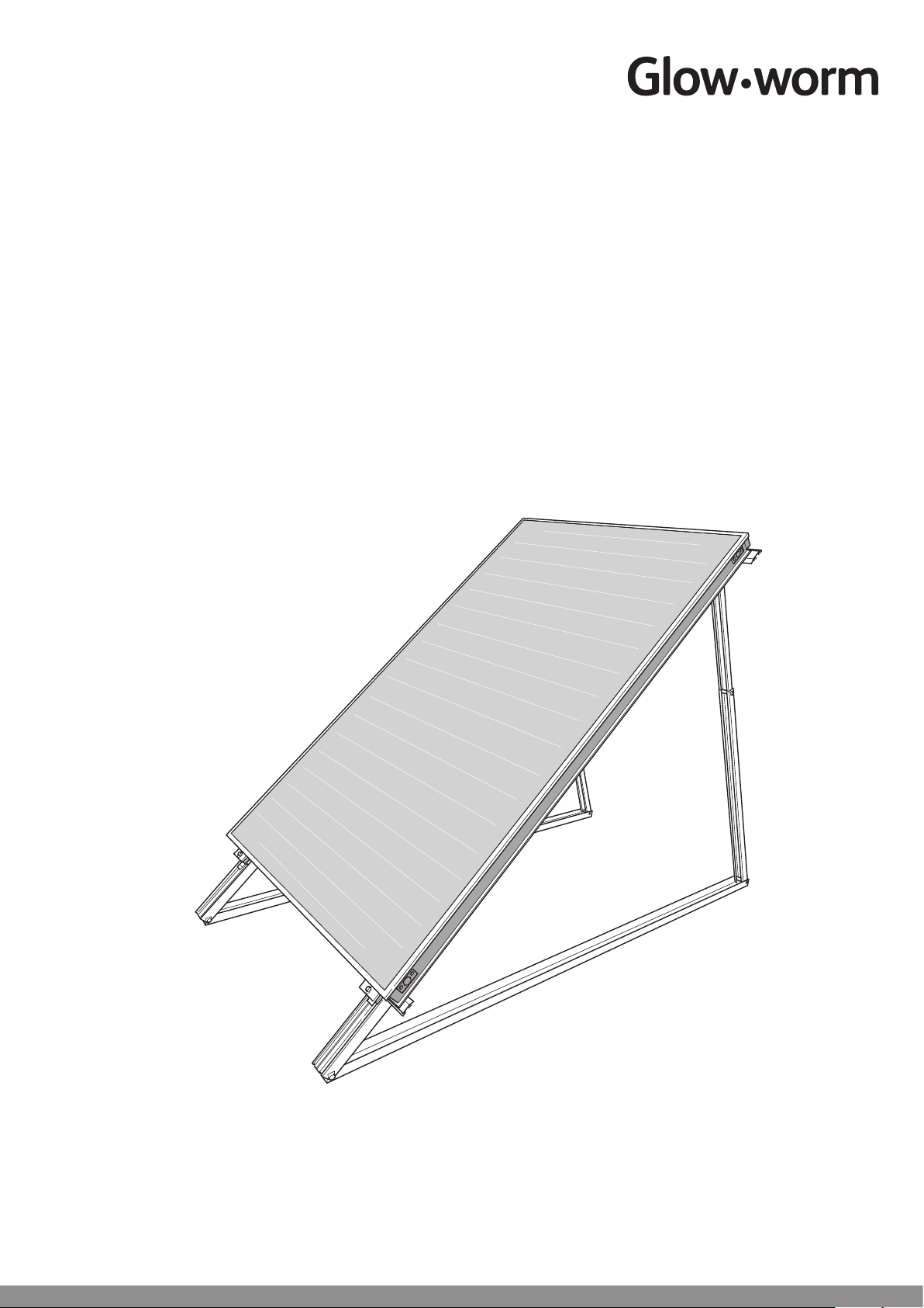
Clearly Solar
Solar Thermal Flat Plate Collector
Installation Instructions
Flat Surface Mounting
SRH 2.3 and SRV 2.3
www.glow-worm.co.uk
1
Page 2

Guarantee Registration
These Clearly Solar Flat Plate collectors come with a comprehensive manufacturer’s guarantee.
Details of the guarantee, and the terms and conditions that apply can be found on the Guarantee
registration card. We recommend you complete and return this as soon as possible.
Customer Service:
01773 596510
Technical Helpline:
01773 828300
General and Sales enquiries:
Tel. 01773 824639
Fax: 01773 820569
To register your Glow-worm appliance call:
0800 0732142
Benchmark places responsibilities on both manufacturers and installers. The purpose is to ensure that customers are provided
with the correct equipment for their needs, that it is installed, commissioned and serviced in accordance with the manufacturer’s
instructions by competent persons and that it meets the requirements of the appropriate Building Regulations. The Benchmark
Checklist can be used to demonstrate compliance with Building Regulations and should be provided to the customer for future
reference.
Installers are required to carry out installation, commissioning and servicing work in accordance with the Benchmark Code of
Practice which is available from the Heating and Hotwater Industry Council who manage and promote the Scheme.
Visit www.centralheating.co.uk for more information.
2
Page 3

These instructions must be handed to the user on completion of the installation.
CONTENTS DESCRIPTION SECTION PAGE
GENERAL
INFORMATION
TECHNICAL
SPECIFICATION
FLAT SURFACE
MOUNTING
Warnings 4
Important Information 4
Statutory Requirements 5
Technical Specication 1 6
Vertical Collector Technical Data 2 7
Vertical Collector and Hydraulic
Connection Arrangement 3 8
Hydraulic Connection Kits
- Vertical Collector 4 9
Flat Surface Installation
- Vertical Collector 5 10
Horizontal Collector Technical Data 6 17
Horizontal Collector and Hydraulic
Connection Arrangement 7 18
Hydraulic Connection Kits
- Horizontal Collector 8 19
Flat Surface Installation
- Horizontal Collector 9 20
3
Page 4

WARNINGS
Metal Parts
This solar panel contains metal parts (components) and care should be taken when handling,
with particular regard to edges.
Risk of death from falls and falling objects
Observe the national regulations for working at heights.
Danger of burning and scalding
In case of solar irradiation inside the units, solar panels can reach 200°C.
Remove the sun protection lm installed at the factory only after the solar energy system has been started up.
Sealed Components
Under no circumstances must the user interfere with or adjust sealed parts.
Important Information
General
These instructions must be handed to the user on completion
of the installation.
This installation instruction applies exclusively to the mounting
of the solar collector.
The solar collector is one component in a solar system and
it is recommended that you read all other component(s)
literature prior to installation.
We accept no liability for any damage caused by failure to
observe these instructions.
Control of Substances Hazardous to Health
Under Section 6 of The Health and Safety at Work Act
1974, we are required to provide information on substances
hazardous to health.
The adhesives and sealants used in this appliance are cured
and give no known hazard in this state.
Solar uid
For solar uid safety data, please refer to Clearly Solar
System Hydraulics literature.
Manual Handling
With regards to the “Manual Handling Operations, 1992
Regulations”, this product exceeds the recommended weight
for a one man lift.
Recommend 2 person lift. Ensure safe lifting techniques are
used – keep back straight – bend using legs. Keep load as
close to body as possible. Ensure co-ordinated movements
during lift. Clear the route before attempting the lift. If
removing from truck straddle the load and tilt forwards to
facilitate secure grip. Do not twist – reposition feet instead.
Take care to avoid trip hazards, slippery or wet surfaces and
when climbing steps or ladders. Always use assistance if
required.
Installation of the solar collector will require a risk
assessment.
Testing and Certication
This solar collector is tested and certicated for safety and
performance. It is, therefore, important that no alteration is
made, without permission, in writing, by Glow-worm.
Any alteration not approved by Glow-worm, could invalidate
the certication, warranty and may also infringe the current
issue of the statutory requirements.
CE Mark
The CE mark on the solar collector indicates that it complies
with the basic requirements of the applicable directives as
stated on the data label.
Damage from lightning
If the installation height is more than 20m, electro-conductive
components must be connected to a lightning protection
device.
Frost Protection
Under no circumstances should water be in the solar collector
if there is a danger of frost.
After pressurisation and ushing, the solar collector(s) may
contain water residue.
Water remaining in the solar circuit will dilute the uid.
Immediately ll the solar system with solar uid. Check the
uid concentration with a frost protection tester.
4
Page 5

Statutory Requirements
IMPORTANT
Where no British Standards exists, materials and equipment
should be t for their purpose and of suitable quality and
workmanship.
The installation of this solar collector panel must be carried
out by a competent person in accordance the rules in force
in the countries of destination.
Manufacturer’s instructions must not be taken as overriding
statutory requirements.
Statutory Requirements
In GB, the installation of the solar collector panel must comply
with the requirements of the current issue of the following
regulations:
The manufacturer’s instructions supplied.
The appropriate Buildings Regulations either The Building
Regulations, The Building Regulations (Scotland),The
Building Regulations (Northern Ireland).
Working at Heights Regulations 2005.
Connecting thermal solar appliances.
Lightning protection requirements.
Equipotential bonding of electrical installations.
The Health and Safety at Work Act
Control of Substances Hazardous to Health (COSHH).
The Current I.E.E. Wiring Regulations.
The Water Supply (water ttings) Regulations 1999 or the
Water Byelaws 2000 (Scotland).
Where no specic instructions are given, reference should be
made to the relevant British Standard Code of Practice.
Regulations for the prevention of accidents
At all times follow the national regulations on working at
heights.
Make sure there is suitable safety equipment such as
scaffolding or protective walls to prevent falling from roofs.
Fall protection systems such as the Glow-worm fall protection
system (item no. 0020054985) also has a fall arresting device
if the roof scaffold and protective roof wall are inappropriate
for the specic task.
Only use tools and equipment such as lifting gear or ladders
in accordance with the lifting regulations.
Cordon off areas below the working area sufciently to protect
people from falling objects.
Mark the working area, for example with warning signs as
described by the national regulations.
5
Page 6

1 Technical Specication
Design Description
The Clearly Solar, solar at plate collector, collects the
available solar radiation and transfers the heat through the
solar uid to be utilised by the system.
It has been designed to compliment the complete range of
Glow-worm solar system components.
The kits are suitable for at roof or at surface installation.
The solar thermal at plate collector includes a saltwater-
resistant aluminium frame as well as a copper surface
absorber with a high selective coating.
The at plate collector has a CFC-free, standstill temperature-
resistant mineral wool insulation for long-life and excellent
heat insulation.
Hydraulic connections are tool free with double ‘O’ ring
sealing. The sensor sleeve is integrated into the hydraulic ow
connection.
Hydraulic connections are push-t with double ‘O’ ring
sealing. The sensor sleeve is integrated into the hydraulic ow
connection.
IMPORTANT: The completed works shall comply with all
necessary BS EN Standards and Codes of practice as well
as Building control or planning requirements, these should be
conrmed where necessary by notication to building control
or the appropriate competence based notication body.
The following kits are available and dependant upon the
number of collectors, the quantities required are listed in the
following table and illustrated in the appropriate sections:-
Number of collectors: 1 2 3 4 5 6 7 8 9 10 11 12
Gravel tray Part number 0020059905
Easy fit hydraulic connection set - Section 4.
Part number 0020060207
Easy fit hydraulic extension set - Section 4.
Part number 0020059909
Vertical
Vertical frame Part number 0020060312
Diagram 5.1.
collector position
Vertical rail, aluminium
Part number 0020060308 - Diagram 5.1.
Gravel tray art.-no. 0020059904
Easy fit hydraulic connection set - Section 4.
Part number 0020060207
Easy fit hydraulic extension set - Section 4.
Part number 0020059909
Horizontal frame Part number 0020060311
Horizontal
Diagram 9.1.
collector position
Horizontal rail, aluminium
Part number 0020060307 - Diagram 9.1.
2 3 4 5 6 7 8 9 10 11 12 13
- 1 2 3 4 5 6 7 8 9 10 11
2 3 4 5 6 7 8 9 10 11 12 13
2 4 6 8 10 12 14 16 18 20 22 24
2 3 4 5 6 7 8 9 10 11
- 1 2 3 4 5 6 7 8 9
2 3 4 5 6 7 8 9 10 11
1 2 3 4 5 6 7 8 9 10
1
1
Flat surface installation components
6
Page 7
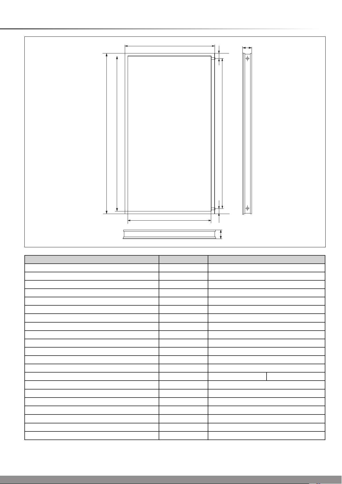
2 Vertical Collector Technical Data
2033
1978
1233
79
80
14922
1875
1178
79
80
Diagram 2.1Vertical Collector
Appliance designation Unit. Clearly Solar
Absorber type Serpentine
Gross area m
Aperture surface area m
Absorber surface area m
2
2
2
Absorber Aluminium (vacuum coated) 0.5 x 1178 x 1978
Dimensions (L x W x H) mm 2033 x 1233 x 80
Weight (Dry) kg 38
Fluid content l 1.85
Copper pipe connection, at-face Ø mm G 3/4" (DN16)
Insulation thickness mm 40
Max. operating pressure bar 10
Glass type Solar safety glass (prismatic structure)
Glass covering mm 3.2 (thickness) x 1233 x 2033
Coating High selective (blue) α = 95% ε = 5%
Transmission %
2
Back wall insulation mm, W/m
K, kg/m340 λ = 0.035 ρ = 55
Stagnation temperature °C 210
Efciency η
0
% 80
Heat capacity Ws/m•K 5014
Heat loss factor k
Heat loss factor k
1
2
W/m2•K 3.7
W/m2•K
2
2.51
2.35
2.33
t = 91
0,012
7
Page 8

3 Vertical Collector and Hydraulic Connection Arrangement
Collector Panel
The recommended collector panel arrangements are shown
below.
Vertical
THE HYDRAULIC FLOW CAN BE TOP AND BOTTOM OR DIAGONAL
1-5 Collectors
1 4 5...
TOP & BOTTOM DIAGONAL
6 and up to 12 max Collectors
THE HYDRAULIC FLOW MUST BE DIAGONAL
Hydraulic Connections
It is recommended that the hydraulic connections should be
made as shown below.
15025
1 4 5...
14915
1
2
...
DIAGONAL
11
12
Diagram 3.1
8
Page 9
15303
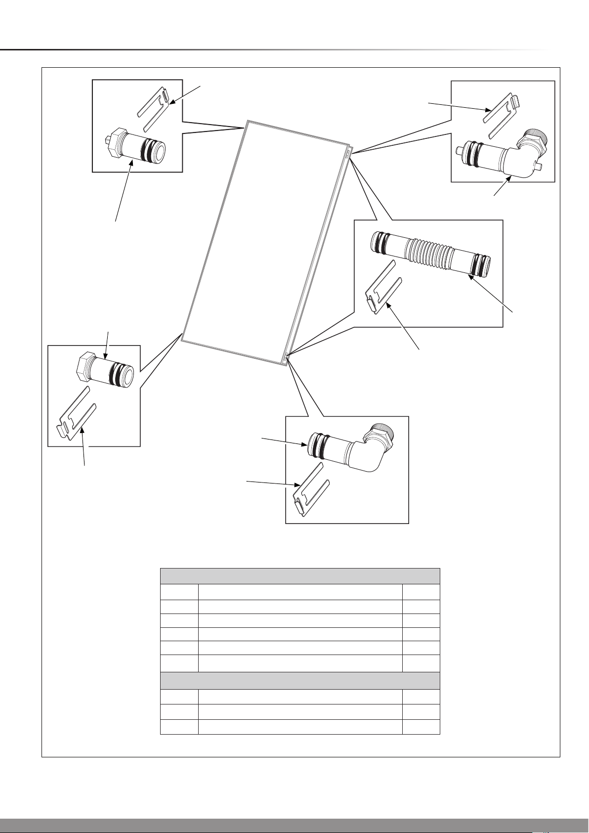
4 Hydraulic Connection Kits - Vertical Collector
5
5
1
4
6
3
7
2
5
Easy fit hydraulic connection set - Part No. 0020060207
Part Description Qty.
1 Upper supply (with probe) 1
2 Return (inlet) 1
3 Lower plug 1
4 Upper plug (with ventilation) 1
5 Securing clip 4
5
Easy fit hydraulic extension set - Part No. 0020059909
Part Description Qty.
6 Pipe coupling 2
7 Securing clip 4
9
Diagram 4.1
Page 10

5 Flat Surface Installation - Vertical Collector
1
14998
2
4
3
Flat Surface Mounting Kit
Flat surface mounting kit
Part Description Qty.
1 Mounting rail 2
2 Frame with clamping assembly 1
3 Safety clamp 2
4 Gravel tray (optional) 2-3
Diagram 5.1
10
Page 11

5 Flat Surface Installation - Vertical Collector
5.1 Flat surface installation
IMPORTANT
● Do not remove the protection lm until the system is to be
commissioned.
● With due regard to the complete weight of the solar
collector system, (refer to technical data) ensure the
surface is at and has a sufcient load carrying capacity.
● Ensure that a roof surface is adequately protected and
watertight.
The at surface frames allow the collectors to be installed at
an angle of 30°, 45° or 60°.
The mounting rails can be adjusted to compensate for oor
irregularities.
Angle 0-10 m 10-18 m 18-25 m
30° 159 Kgs 178 Kgs 197 Kgs
45° 225 Kgs 252 Kgs 279 Kgs
60° 276 Kgs 309 Kgs 342 Kgs
Table 5.1
5.2 Ballast and frame weight
Dene the necessary load required to secure the frame and
collector, refer to Table 5.1.
For the required space and the distances among collectors,
refer to Table 5.2.
Height above ground
B
(30° 45° 60°)
Number of
collectors
1* 1136
2 2300
3 3563
4 4826
5 6089
6 7352
7 8615
E
A
C
F
D
(30° 45° 60°)
C
8 9878
9 11141
10 12404
30° 45° 60°
A
B F B F B F
1283
4400
1740
6100
2080
7200
C D A
- -
2357
1150
-
1263
* Possible only with 4 offset gravel trays.
Table 5.2
11
Page 12

5 Flat Surface Installation - Vertical Collector
5.3 Collector Installation
NOTE: Roof installation
With due regard to the complete weight of the ballast, frame,
collector and system, proceed as follows:
14999
With the oor section secured (screwed or gravel trays) to the
at surface, x the lower telescopic section with retaining pin
and safety clip, see diagram 5.2.
NOTE: If gravel trays are used, slide the gravel tray onto the
oor section before xing the lower telescopic section, see
diagram 5.3.
Apply the safety clamps from the top oor sections (2x frame)
to x the gravel tray.
Collectors should have 3 gravel trays per frame.
Extend the telescopic sections until the hole of the desired
position is aligned, then secure with retaining pin and safety
clip, see diagram 5.4.
You can choose 30º, 45º or 60º, the standard is 45º.
SAFETY
CLIP
RETAINING
PIN
FLOOR
SECTION
Diagram 5.2
14933
SAFETY
CLAMPS
RETAINING
PIN
GRAVEL
TRAY
Diagram 5.3
SAFETY
CLIP
14934
12
Diagram 5.4
Page 13

5 Flat Surface Installation - Vertical Collector
Fix the lower mounting rail with the frame clamping assembly,
see diagram 5.5.
If multiple collectors are mounted, the mounting rails meet in
the centre of the clamping assemblies, see diagram 5.6.
On the rst and last frame, the mounting rails can be
projected by 20mm.
Insert the mounting rail connector into the mounting rails, see
diagram 5.6
Position another frame (see diagrams 5.1 to 5.3).
Join the mounting rails and x them to the frame clamping
assemblies as shown in diagram 5.7.
Compensate any difference in height by moving the clamping
assembly.
LOWER
MOUNTING RAIL
CLAMPING
ASSEMBLY
15000
Diagram 5.5
MOUNTING RAIL
CONNECTOR
MOUNTING
RAIL
15004
Diagram 5.6
15003
13
MOUNTING RAIL
(First and last frame only)
Diagram 5.7
Page 14

5 Flat Surface Installation - Vertical Collector
Place the collector with the lower edge in the section of the
mounting rail, see diagram 5.8.
Make sure that the upper part of the clamping assembly is
above the collector edge.
Slide the upper mounting rail until it is ush with the collector.
Make sure that the upper part of the clamping assembly is
above the collector edge, see diagram 5.9.
Tighten the lower clamping assemblies with the socket/
combination wrench (SW13).
CLAMPING
ASSEMBLY
15404
COLLECTOR
LOWER EDGE
LOWER
MOUNTING
RAIL
Diagram 5.8
CLAMPING
ASSEMBLY
UPPER
MOUNTING
RAIL
15001
COLLECTOR
EDGE
Diagram 5.9
14
Page 15

5 Flat Surface Installation - Vertical Collector
Remove the plugs from the openings of the collector and
insert the pipe couplings up to their stops, see diagram 5.10.
Slide the retaining clips into place to secure the pipe
couplings.
NOTE: The collector design is symmetrical and does not have
a top or bottom.
Place the next collector on the lower mounting rail and slide
towards the rst collector.
Secure the pipe couplings to the second collector with the
securing clips.
Tighten the clamping assemblies of the rst collector with the
socket/ combination wrench (SW13).
With regards to the hydraulic system you have chosen, insert
and secure the hydraulic connections, see diagram 5.9.
Insert the collector sensor into the appropriate elbow (ow,
top), see diagram 5.11. The collector sensor is packed with
the Fluropro controller, part no. 0020054960.
Mount the plug with the bleed valve (vent) in the opposite top
position.
PIPE
COUPLING
SECURING
CLIP
Diagram 5.10
15005
Connect the collector to the system circuit.
UPPER PLUG
WITH VENT
LOWER PLUG
SECURING
CLIP
FLOW
ELBOW (with sensor)
15006
SECURING
CLIP
RETURN
ELBOW (inlet)
SECURING
CLIP
TOP AND BOTTOM OR DIAGONAL FLOW
1-5 Collectors
15
SECURING
CLIP
Diagram 5.11
Page 16

5 Flat Surface Installation - Vertical Collector
Ensure that all of the following steps have been performed:-
- All the connections have been xed with securing clips.
- All hydraulic connections laid properly.
- The collector sensor has been connected.
- The collector is connected to a lightning protection device.
- A pressure test.
- All insulation is intact.
NOTE: After initial commissioning and according to the
season, high outside temperature oscillations can cause
condensation in the collector, this is normal.
FLOW
ELBOW
(with sensor)
LOWER PLUG
SECURING
CLIP
15008
UPPER PLUG
WITH VENT
SECURING
CLIP
SECURING
CLIP
RETURN
ELBOW (inlet)
SECURING
CLIP
DIAGONAL FLOW
6 and up to 12 Collectors
16
Diagram 5.10
Page 17

6 Horizontal Collector Technical Data
80
1233
79
1075
79
2033
1978
14921
1178
Horizontal Collector
Diagram 6.1
Appliance designation Unit. Clearly Solar
Absorber type Serpentine
Gross area m
Aperture surface area m
Absorber surface area m
2
2
2
2.51
2.35
2.33
Absorber Aluminium (vacuum coated) 0.5 x 1178 x 1978
Dimensions (L x W x H) mm 1233 x 2033 x 80
Weight (Dry) kg 38
Fluid content l 2.16
Copper pipe connection, at-face Ø mm G 3/4" (DN16)
Insulation thickness mm 40
Max. operating pressure bar 10
Glass type Solar safety glass (prismatic structure)
Glass covering mm 3.2 (thickness) x 2033 x 1233
Coating High selective (blue)
Solar safety glass transmission t (dew)
Absorber emission ε (epsilon)
%
t = 91
% 5 ± 2
α = 95% ε = 5%
Back wall insulation mm, W/mk, kg/m 95 ± 2
Stagnation temperature °C 210
Efciency η
0
% 80
Heat capacity Ws/ (m•K) 5014
2
Efciency coefcient k1 W/(m
Efciency coefcient k2 W/(m
•K) 3.7
2
•K2) 0,012
17
Page 18

7 Horizontal Collector and Hydraulic Connection Arrangement
Collector Panel
The recommended collector panel arrangements are shown
below.
Horizontal
1-5 Collectors
THE HYDRAULIC FLOW CAN BE DIAGONAL OR TOP AND BOTTOM
1
...
6 and up to 10 max Collectors
THE HYDRAULIC FLOW MUST BE DIAGONAL
1
...
Hydraulic Connections
It is recommended that the hydraulic connections should be
made as shown below.
15045
4 5
9 10
Diagram 7.1
18
Page 19

8 Hydraulic Connection Kits - Horizontal Collector
4
5
5
15305
1
6
3
5
7
2
5
Easy fit hydraulic connection set - Part No. 0020060207
Part Description Qty.
1 Upper supply (with probe) 1
2 Return (inlet) 1
3 Lower plug 1
4 Upper plug (with ventilation) 1
5 Securing clip 4
Easy fit hydraulic extension set - Part No. 0020059909
6 Pipe coupling 2
7 Securing clip 4
19
Diagram 8.1
Page 20

9 Flat Surface Installation - Horizontal Collector
1
15136
2
3
4
Flat Surface Mounting Kit
On-roof mounting kit
Part Description Qty.
1 Mounting rail 2
2 Frame with clamping element 1
3 Gravel tray (optional) 2-3
4 Safety clamps 2
Diagram 9.1
20
Page 21

9 Flat Surface Installation - Horizontal Collector
9.1 Flat surface installation
IMPORTANT
● Do not remove the protection lm until the system is to be
commissioned.
● With due regard to the complete weight of the solar
collector system, (refer to technical data) ensure the
surface is at and has a sufcient load carrying capacity.
● Ensure that a roof surface is adequately protected and
watertight.
The at surface frames allow the collectors to be installed at
an angle of 30°, 45° or 60°.
The mounting rails can be adjusted to compensate for oor
irregularities.
Angle 0-10 m 10-18 m 18-25 m
30° 159 178 197
45° 225 252 279
60° 276 309 342
9.2 Ballast and frame weight
Dene the necessary load required to secure the frame and
collector, refer to Table 9.1.
For the required space and the distances among collectors,
refer to Table 9.2.
Height above ground
Table 9.1
B
(30° 45° 60°)
Number of
collectors
1* 1650
2 3900
3 5963
4 8026
5 10089
6 12152
E
A
D
(30° 45° 60°)
7 14215
8 16278
9 18341
10 20404
30° 45° 60°
A
B F B F B F
883
3100
1173
4100
1387
4800
C D E
- -
1812
1950
-
2063
C
* Possible only with 4 offset gravel trays.
F
Table 9.2
C
21
Page 22

9 Flat Surface Installation - Horizontal Collector
9.3 Collector Installation
NOTE: Roof installation
With due regard must to the complete weight of the ballast,
frame, collector and system, proceed as follows:
With the oor section secured (screwed or gravel trays) to the
at surface, x the lower telescopic section with retaining pin
and safety clip, see diagram 9.1.
NOTE: If gravel trays are used, slide the gravel tray onto the
oor section before xing the lower telescopic section, see
diagram 9.2.
Apply the safety clamps from the top oor sections (2x frame)
to x the gravel tray.
Collectors should have 3 gravel trays per frame.
Extend the telescopic sections until the hole of the desired
position is aligned, then secure with retaining pin and safety
clip, see diagram 9.3.
You can choose 30º, 45º or 60º, the standard is 45º.
14999
SAFETY
CLIP
RETAINING
PIN
Diagram 9.1
RETAINING
PIN
SAFETY
CLAMPS
GRAVEL
TRAY
Diagram 9.2
SAFETY
CLIP
14933
14934
22
Diagram 9.3
Page 23

9 Flat Surface Installation - Horizontal Collector
Fix the lower mounting rail with the frame clamping assembly,
see diagram 9.4.
If multiple collectors are mounted, the mounting rails meet in
the centre of the clamping assemblies, see diagram 5.5.
On the rst and last frame, the mounting rails can be
projected by 20mm.
Insert the mounting rail connector into the mounting rails, see
diagram 9.5
Position another frame (see diagrams 9.1 to 9.3).
Join the mounting rails and x them to the frame clamping
assemblies as shown in diagram 9.6.
Compensate any difference in height by moving the clamping
assembly.
CLAMPING
ASSEMBLY
15156
LOWER
MOUNTING
RAIL
Diagram 9.4
MOUNTING RAIL
CONNECTOR
MOUNTING
RAIL
15004
Diagram 9.5
15003
23
MOUNTING RAIL
(First and last frame only)
Diagram 9.6
Page 24

9 Flat Surface Installation - Horizontal Collector
Place the collector with the lower edge in the section of the
mounting rail, see diagram 9.7.
Make sure that the upper part of the clamping assembly is
above the collector edge.
Slide the upper mounting rail until it is ush with the collector.
Make sure that the upper part of the clamping assembly is
above the collector edge, see diagram 9.8.
Tighten the lower clamping assemblies with the socket/
combination wrench (SW13).
CLAMPING
ASSEMBLY
15404
COLLECTOR
LOWER EDGE
LOWER
MOUNTING
RAIL
Diagram 9.7
CLAMPING
ASSEMBLY
15001
COLLECTOR
EDGE
Diagram 9.8
24
Page 25

9 Flat Surface Installation - Horizontal Collector
Remove the plugs from the openings of the collector and
insert the pipe couplings up to their stops, see diagram 9.9.
Slide the retaining clips into place to secure the pipe
couplings.
NOTE: The collector design is symmetrical and does not have
a top or bottom.
Place the next collector on the lower mounting rail and slide
towards the rst collector.
Secure the pipe couplings to the second collector with the
securing clips.
Tighten the clamping assemblies of the rst collector with the
socket/ combination wrench (SW13), see diagrams 9.10 and
9.11.
With regards to the hydraulic system you have chosen, insert
and secure the hydraulic connections, see diagram 9.10.
Insert the collector sensor into the appropriate elbow (ow,
top), see diagram 9.10. The collector sensor is packed with
the Fluropro controller, part no. 0020054960.
Mount the plug with the bleed valve (vent) in the opposite top
position.
PIPE
COUPLING
SECURING
CLIP
Diagram 9.9
15157
SECURING
CLIP
UPPER PLUG
WITH VENT
FLOW
ELBOW
(with sensor)
SECURING
CLIP
15158
SECURING
CLIP
RETURN
ELBOW
LOWER PLUG
TOP AND BOTTOM OR DIAGONAL FLOW
(inlet)
1-5 Collectors
25
SECURING
CLIP
Diagram 9.10
Page 26

9 Flat Surface Installation - Horizontal Collector
Connect the collector to the system circuit.
Ensure that all of the following steps have been performed:-
- All the connections have been xed with securing clips.
- All hydraulic connections laid properly.
- The collector sensor has been connected.
- The collector is connected to a lightning protection device.
- A pressure test.
- All insulation is intact.
NOTE: After initial commissioning and according to the
season, high outside temperature oscillations can cause
condensation in the collector, this is normal.
SECURING
CLIP
15159
SECURING
CLIP
UPPER PLUG
WITH VENT
FLOW
ELBOW
(with sensor)
LOWER PLUG
RETURN
ELBOW (inlet)
SECURING
CLIP
SECURING
CLIP
DIAGONAL FLOW
6 and up to 12 Collectors
26
Diagram 9.11
Page 27

27
Page 28

0020077782-02 03.09
Because of our constant endeavour for improvement, details
may vary slightly from those shown in these instructions.
Glow-worm, Nottingham Road, Belper, Derbyshire. DE56 1JT
28
 Loading...