

Page 1
Installation
and Servicing
Hydraulic module HB
Page 2

Page 3

TABLE OF CONTENTS
INTRODUCTION
1 Instructions guidance .........................................................................................................................2
1.1 Product documentation...........................................................................................2
1.2 Associated documents ..........................................................................................2
1.3 Explanation of symbols...........................................................................................2
1.4 Guarantee registration ............................................................................................2
2 Appliance description .........................................................................................................................2
2.1 Safety devices ........................................................................................................ 2
2.2 Data label ...............................................................................................................2
2.3 Hydraulic schematic ...............................................................................................3
3 Safety instructions and regulations ....................................................................................................3
3.1 Safety instructions .................................................................................................. 3
3.2 Regulations.............................................................................................................4
4 Recycling ...........................................................................................................................................4
4.1 Appliance ................................................................................................................4
4.2 Packaging ...............................................................................................................4
INSTA L L ATION
5 Appliance location ..............................................................................................................................5
6 Appliance installation ........................................................................................................................5
6.1 Scope of delivery ....................................................................................................5
6.2 Recommendations before installing .......................................................................5
6.3 Dimensions .............................................................................................................6
6.4 Mounting .................................................................................................................6
7 Hydraulic connection ..........................................................................................................................8
8 Electrical connections ........................................................................................................................9
9 Commissioning ..................................................................................................................................9
10 Specic adjustment ...........................................................................................................................9
11 Assembly of the casing ....................................................................................................................10
12 User information ...............................................................................................................................10
MAINTENANCE
13 Trouble-shooting .............................................................................................................................. 11
14 Servicing ........................................................................................................................................ 11
15 Replacement of Parts ......................................................................................................................11
16 Technical Data .................................................................................................................................11
- 1 -
Page 4
INTRODUCTION
INTRODUCTION
1 Instructions guidance
1.1 Product documentation
The instructions are an integral part of the appliance and must
be handed to the user on completion of the installation in order
to comply with the current regulation.
• Carefully read the manual, to understand all the information
to enable safe installation, use and servicing. No liability can
be accepted in the event of damage for not complying with
the guidance in this instruction manual.
1.2 Associated documents
- 1 Instructions for use
- Instructions for other system components
1.3 Explanation of symbols
We recommend you complete and return as soon as possible
your guarantee registration card. If your guarantee registration
card is missing you can obtain a copy or record your registration
by telephoning the Glow-worm Customer Service number
01773 828100.
2 Appliance description
2.1 Safety devices
This appliance is equipped with a safety valve.
- The safety valve opens when the pressure in the heat pump
circuit exceeds 3 bars.
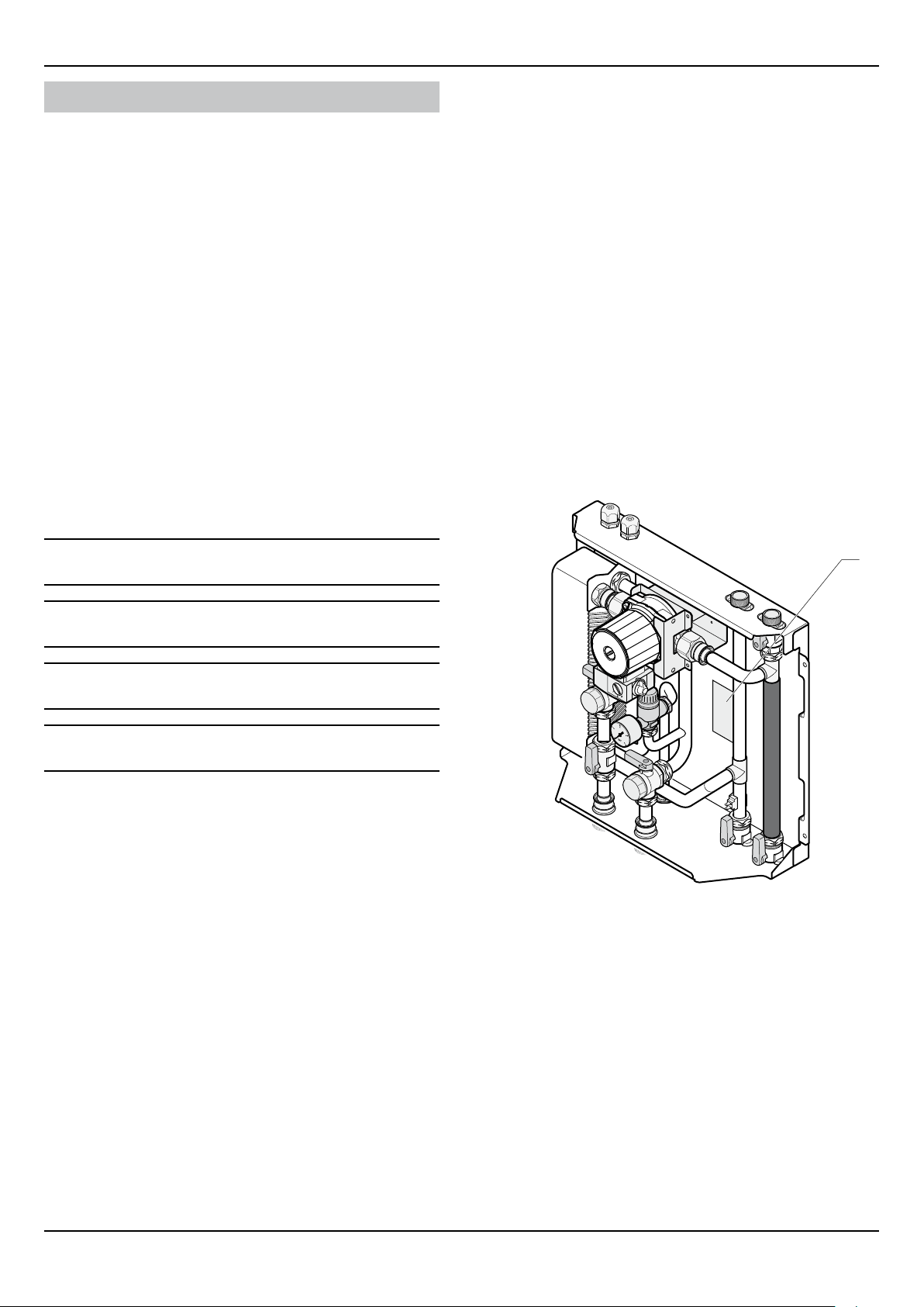
2.2 Data label
The data label certies the country where the appliance is
intended to be installed.
Data label location:
a
e
b
i
DANGER: Risk of injuries.
DANGER: Risk of electric shock.
ATTENTION: Risk of damage to the appliance or
to its surroundings.
IMPORTANT: Important information.
1.4 Guarantee registration
Thank you for installing a new Glow-worm appliance in your home.
Glow-worm appliances are manufactured to the very
highest standard so we are pleased to offer our customers a
Comprehensive Guarantee.
This product is guaranteed for 24 months from the date
of installation or 30 months from the date of manufacture,
whichever is the shorter, for parts and labour.
The second year of guarantee, from the beginning of the
13th month onwards after installation or manufacture, is
conditional upon the appliance having been serviced by a
competent person approved at the time by the Health and
Safety Executive, in accordance with the manufacturer’s
recommendations. We strongly recommend regular servicing
of your gas appliance, but where the condition is not met,
any chargeable spare parts or components issued within
the applicable guarantee period still benet from a 12 month
warranty from the date of issue by the manufacturer.
1
Key
1 Data label
The data label contains the following data:
- The name of the manufacturer
- The commercial name of the appliance and its serial number
- The maximum pressure in the heating circuit
- The maximum pressure in the heat pump circuit
- The type and voltage of electricity supply
- 2 -
0020096881_02 - 08/10 - Glow-worm
Page 5
INTRODUCTION
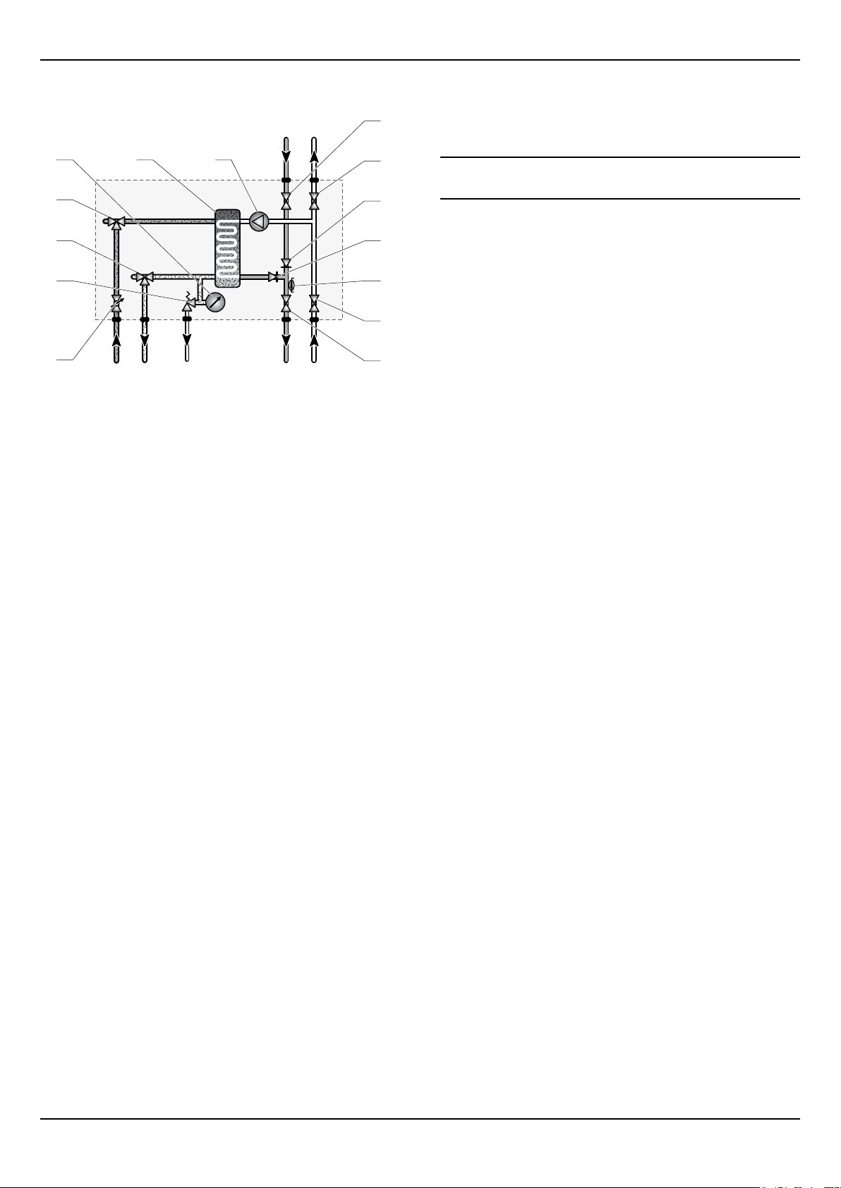
2.3 Hydraulic schematic
5
4
3
2
1
Key
1 Flow control valve
2 Safety valve
3 3-wayvalvewithshut-offvalveforlling
4 3-wayvalvewithshut-offvalveforlling
5 Manometer
6 Plate to plate heat exchanger
7 Pump
8 Boilerowcircuitisolatingvalve
9 Boiler return circuit isolating valve
10 Boilerowcircuitnon-returnvalve
11 Heat exchanger output non-return valve
12 Heatingowthermistor
13 Heating return circuit isolating valve
14 Heatingowcircuitisolatingvalve
6
7
E
A B
D CG F
10
11
12
13
14
3 Safety instructions and regulations
8
9
3.1 Safety instructions
Incorrect installation can cause electric shock or
e
• Never disable security devices and do not try to adjust them.
• Be sure to consider the following handling techniques and
- Grip the appliance at its base
- Use safety clothing where appropriate, e.g. gloves, safety
• Ensure safe lifting techniques are used:
- Keep back straight.
- Avoid twisting at the waist.
- Avoid upper body/top heavy bending.
- Always grip using the palm of the hand.
- Use designated hand holds.
- Keep load as close to body as possible.
- Always use assistance if required.
• Under no circumstances must the user interfere with or
appliance damage.
precautions:
footwear.
adjust sealed parts.
A Boilerowcircuit
B Boiler return circuit
C Heating return circuit
D Heatingowcircuit
E Safety valve discharge
F Heat pump return circuit
G Heatpumpowcircuit
• When assembling the connections, correctly position the
seals to avoid any leakage of water.
• This appliance contains metal parts (components) and care
should be taken when handling and cleaning, with particular
regard to edges.
The basic safety instructions must be followed before
attempting to maintain or replace spare parts:
• Stop the appliance.
• Electrically isolate the appliance from the power supply.
• Hydraulically isolate the appliance using the isolation valves
if provided.
• Should you need to replace hydraulic components, drain the
appliance.
• Protect all the electrical components from water while
working on the appliance.
• Use only original spare parts.
• Use only new O-rings and gaskets.
• After having completed work on water carrying components,
check for their tightness.
0020096881_02 - 08/10 - Glow-worm
• When work on the appliance is completed, perform an
operational test and check for safety.
- 3 -
Page 6
INTRODUCTION
3.2 Regulations
IMPORTANT
Where no British Standards exists, materials and equipment
should be t for their purpose and of suitable quality and
workmanship.
The installation of this appliance must be carried out by a
competent person approved at the time by the Health and
Safety Executive and in accordance with the rules in force in the
countries of destination.
Manufacturer’s instructions must not be taken as overriding
statutory requirements.
Statutory Requirements
In GB, the installation of the appliance must comply with the
requirements of the current issue of BS6798 and be carried out
by a competent person approved at the time by the Health and
Safety Executive and as described in the following regulations:
- The manufacturer’s instructions supplied.
- The Gas Safety (Installation and Use) Regulations.
- The appropriate Buildings Regulations either The Building
Regulations, The Building Regulations (Scotland), The Building
Regulations (Northern Ireland).
- The Water Supply (water ttings) Regulations 1999 and water
byelaws 2000, Scotland.
- The Health and Safety at Work Act, Control of Substances
Hazardous to Health (COSHH).
- The Current I.E.E. Wiring Regulations.
Domestic Hot Water
All domestic hot water circuits, connections, ttings must be
in accordance with the relevant standards and water supply
regulations.
GB: Guidance G17 to G24 and recommendation R17 to R24 of
the Water Regulations Guide.
IE: The current edition of I.S.813 “Domestic Gas Installations”.
Heating System
In GB, it is necessary to comply with the Water Supply (Water
Fittings) Regulations 1999 (for Scotland, the Water Byelaws
2000, Scotland). To comply with the Water regulations your
attention is drawn to: The Water Regulations guide published
by the Water Regulations Advisory Service (WRAS) gives full
details of the requirements.
In IE, the requirements given in the current edition of I.S.813
“Domestic Gas Installations” and the current Building
Regulations must be followed.
4 Recycling
The recycling of the packaging must be carried
i
out by the qualied professional who installed the
appliance.
Where no specic instructions are given, reference should be
made to the relevant British Standard Code of Practice.
In IE, the installation must be carried out by a competent person
approved at the time by the Health and Safety Executive and
installed in accordance with the current edition of I.S.813
“Domestic Gas Installations”, the current Building Regulations
and reference should be made to the current ETCI rules for
Electrical Installation.
GB: the following Codes of Practice apply: BS4814, BS6798,
BS5440 Part 1 and 2, BS5546 Part 1, BS5449, BS6891,
BS6700, BS7074 Part 1 and 2, BS7593, BS7671.
IE: I.S.813, BS5546, BS 5449, BS 7074, BS 7593.
NOTE: For further information, see the current issue of the
Building Regulations, approved document L1 ( in the UK) and
the following current issues of:
1) Central heating system specication (CheSS) and
2) Controls for domestic central heating system and hot water.
BRECSU.
Gas Supply
The gas installation must be in accordance with the relevant
standards.
In GB, this is BS6891.
In IE, this is the current edition of I.S.813 “Domestic Gas
Installations”.
4.1 Appliance
Most of the appliance is made of recyclable materials.
This symbol indicates that this appliance must not
be disposed of with household waste, that it should
be selectively collected for energy recovery, reuse
or recycling.
• Take the appliance to an appropriate collection point.
By complying with this directive, you will contribute
i
to the preservation of natural resources and the
protection of human health.
4.2 Packaging
We recommend that you recycle the packaging of the appliance
in a responsible fashion.
• Sort the waste in order to separate those elements which
can be recycled (cardboard, plastics ...) and those which
cannot be recycled.
• Dispose of the waste in accordance with existing regulations.
The supply from the governed meter must be of adequate size
to provide a steady inlet working pressure of 20mbar (8in wg) at
the boiler. On completion, test the gas installation for tightness
using the pressure drop method and suitable leak detection
uid, purge in accordance with the above standard.
- 4 -
0020096881_02 - 08/10 - Glow-worm
Page 7

INSTALLATION
INSTALLATION
5 Appliance location
• Before choosing a site for the appliance, carefully read the
safety warnings and installation manual.
• Ensure that wall to which the appliance will be mounted on is
structurally safe in order to support the weight of the appliance.
• Ensure there is sufcient space available for the appliance,
taking care that minimum clearances are adhered to ensure
that the connections to the water can be accessed and
inspected.
• The appliance must be installed in a room protected from
freezing. Take all necessary precautions.
• Explain these requirements to the appliance user.
6 Appliance installation
6.1 Scope of delivery
3.1
2
3
3.2
3.3
3.3 Module instructions for use (x1)
3.4 Guarantee conditions (x1)
3.5 Guarantee card (x1)
4 Frame
5 Accessories bag (x1)
5.1 Flat seal ¾" (x6)
5.2 Frame screws (x4)
5.3 Flat seal 1 " (x4)
• Check the contents of the packages.
(x2)
6.2 Recommendations before installing
6.2.1 Heating circuit design
The heat transmitters may be low temperature (under-oor
heating, low-temp radiator ...) and high temperature (cast iron
radiator ...).
The installation pipework should be calculated using a ow /
pressure curve. The distribution will be determined by the ow
corresponding to the power actually required, regardless of
the maximum power that can be provided by the installation’s
generators.
The pipework should be designed and installed in such a way
so as to make all provisions necessary to avoid air pockets and
facilitate the permanent degassing of the installation. Venting
valves must be placed at each high point of the tubes, as well as
on all radiators.
3.4
3.5
4
5.3
5.2
1
Key
1 Hydraulic module cover (x1)
2 Hydraulic module (x1)
5.1
5
The total volume of water for the heating circuit depends,
among other factors, on the cold static load of the boiler’s
expansion tank. It is recommended that a drainage valve be
installed at the lowest point of the installation.
If using thermostatic valves, do not equip all radiators with
them, placing these valves at high demand sites and never at
the sites in which the room thermostats are installed.
- In both new and existing installations, the radiator circuit
must be ushed prior to installing the new appliance in
accordance with BS:7593.
- If a system component is not put in place immediately,
protect the different connections so that the plaster and paint
does not spoil water tightness for later connecting.
6.2.2 Heat pump circuit design
The pipework should be designed and installed in such a way
so as to make all provisions necessary to avoid air pockets and
facilitate the venting of air from the installation. Bleed valves are
to be installed at each of the pipes' highest points.
• In order to avoid the transmission of vibration to surrounding
structures, use hoses for water connections.
Insulate the pipes with a UV- and high-
b
temperature-resistant insulation.
3 Documents bag (x1)
3.1 System installation manual (x1)
3.2 Module installation manual (x1)
0020096881_02 - 08/10 - Glow-worm
- 5 -
Page 8

INSTALLATION
6.3 Dimensions
6.3.1 Hydraulic module
81
431
65
41
36
i
6.3.2 Frame
Appliance weight : 12,5 kg
34
284
137
85
470
122
157
414
72
6.4 Mounting
Depending on the installation, you may install the
i
• Make sure that the equipment used for implementing the
• Determine the assembly location. See the "Appliance
• The applications should be anchored in accordance with
frame supplied with the appliance.
installation is compatible with that of the appliance.
location" chapter.
the characteristics of the supporting wall and must take into
account the weight of the appliance.
414
- 6 -
476
200
0020096881_02 - 08/10 - Glow-worm
Page 9

INSTALLATION
6.5.1 Attaching the appliance to a wall without a
frame
385
375
Key
1 Hydraulic module
2 Frame
3 Screw
• Attach the frame (2) to the hydraulic module using the
provided screws (3).
385
1
• Attach the appliance to the wall in accordance with the
diagram shown above.
6.5.2 Attaching the appliance to a wall with a frame
2
3
Key
1 Cutting tool
2 Metallic component
Depending on the installation, you can cut the metal
i
• Attach the appliance to the wall in accordance with the
component (2) in order to pass the connections
along the side of the appliance.
diagram shown above.
2
1
0020096881_02 - 08/10 - Glow-worm
33
2
- 7 -
Page 10

INSTALLATION
A
C
7 Hydraulic connection
A label located inside the cover enables the
i
identication of the module’s hydraulic connections.
D Heatingowcircuitؾ"
E Safety valve discharge
F HeatpumpreturncircuitØ1"
G HeatpumpowcircuitØ1"
• Take care to clean the pipes before assembly removing any
debris or burrs. Grease and oils may need to be removed
they are not possible to remove by cleansing and ushing.
1
Foreign bodies in the system may enter the appliance and
interrupt its operation.
• Do not use any solvent products, due to the risk of damaging
the circuit.
Do not perform any 'hot work' directly under
a
• Only use original seals supplied with the appliance.
• Check that there are no leaks.
the appliance, this may cause damage to the
appliance base. Heat may also damage the
isolation valves.
Always pre-assemble pipes before tting them to
the appliance.
Key
1 Hydraulic connection label
B
G
F
Key
A Boilerowcircuitؾ"
B Boilerreturncircuitؾ"
C Heatingreturncircuitؾ"
- 8 -
E
D
0020096881_02 - 08/10 - Glow-worm
Page 11

INSTALLATION
REL1
8 Electrical connections
Incorrect installation can cause electric shock or
e
The external wiring must be earthed, with correct polarity and in
accordance with current standards.
The manufacturer declines any responsibility for damages to
persons or others caused by the incorrect installation of the
appliance earthing. This includes failure to comply with current
standards.
1
2
appliance damage. The electrical connection of
the appliance must be made only by a qualied
engineer.
NTC1
A
A
B
9 Commissioning
• Refer to the system’s installation manual in order to activate
the installation.
Pump ow / pressure curve
21
60
50
40
30
20
10
3
0
Key
1 Speed 2
4
2 Speed 3 (Factory setting)
A Available pressure (kPa)
B Flow in the circuit (l / h)
300 600 900 1200
B
1
Key
1 Pump cable
2 Pump cable gland
3 Heatingowthermistorcable
4 Heatingowthermistorcablegland
Component Voltage (cable section)
Pump 230 V (3 x 0.75 mm ²)
Thermistor 3.3 V (2 x 0.34 mm ²)
i
Speed 1 is not applicable to this system.
10 Specicadjustment
3
• Refer to the system’s installation manual to adjust the
installation.
• Pass the pump cable (1) through the gland (2).
• Connect the cable (1) to the REL1 terminal in the Systempro.
• Tighten the gland (2).
• Pass the thermistor cable (3) through the gland (4).
• Connect the cable (3) to the NTC1 terminal in the Systempro.
• Tighten the gland (4).
0020096881_02 - 08/10 - Glow-worm
- 9 -
Page 12

INSTALLATION
11 Assembly of the casing
1 2
Key
1 Hydraulic module cover
2 Hydraulic module
• Once the installations settings have been completed, t the
cover (1) to the hydraulic module (2).
12 User information
At the end of the installation, the installer must:
- explain the operation of the appliance and its safety devices
to the user, if necessary provide a demonstration and answer
any questions;
- hand over to the user all the required documentation,
- ll in the documents where necessary;
- advise the user of the precautions necessary to prevent
damage to the system, appliance and the building;
- remind the user to service the appliance annually.
- 10 -
0020096881_02 - 08/10 - Glow-worm
Page 13

MAINTENANCE
MAINTENANCE
13 Trouble-shooting
The following checks should be performed before proceeding
onto specic diagnostics:
- Make sure that the electricity supply has not been interrupted
and that the appliance is connected correctly.
• Ensure that the isolating valves are open.
• Check that all external controls are connected correctly.
14 Servicing
• See the "Safety instructions" chapter for a list of operations
to be performed prior to the maintenance of the application.
• Once the maintenance operations have been completed,
refer to the system’s installation manual to restart the
installation.
Annual Maintenance
16 Technical Data
Description Unit Value
Maximum heating circuit pressure
Maximum heat pump circuit pressure
Pump supply voltage V/Hz 230 / 50
Thermistor supply voltage V 3.3
Dimensions
Height mm 476
Length mm 470
Depth mm 200
Lift weight kg 12,5
bar 3
Pa 3 x 10
bar 3
Pa 3 x 10
5
5
• Check the proper functioning of safety devices.
• Check the pressure of the circuits.
• Check the airtightness of the connections.
• Ensure that the appliance’s components are neither worn nor
broken.
15 Replacement of Parts
In order to guarantee the safe and prolonged life of the product,
manufacturers genuine spare parts must be used.
Use only the manufacturer’s authorised, original,
i
• Ensure that spare parts are correctly mounted in the right
new spare parts.
position and direction. After tting any spare part or servicing,
the appliance must be tested for its safe operation.
0020096881_02 - 08/10 - Glow-worm
- 11 -
Page 14

Page 15

Page 16

Glow-worm
Subject to engineering changes
0020096881_02 - 08/10
Nottingham Road,
Belper, Derbyshire.
DE56 1JT
www.glow-worm.co.uk
Because of our constant endeavour for
improvement, details may vary slightly
from those shown in these instructions.
 Loading...