

Page 1
Glow•worm
Clearly Heat Recovery
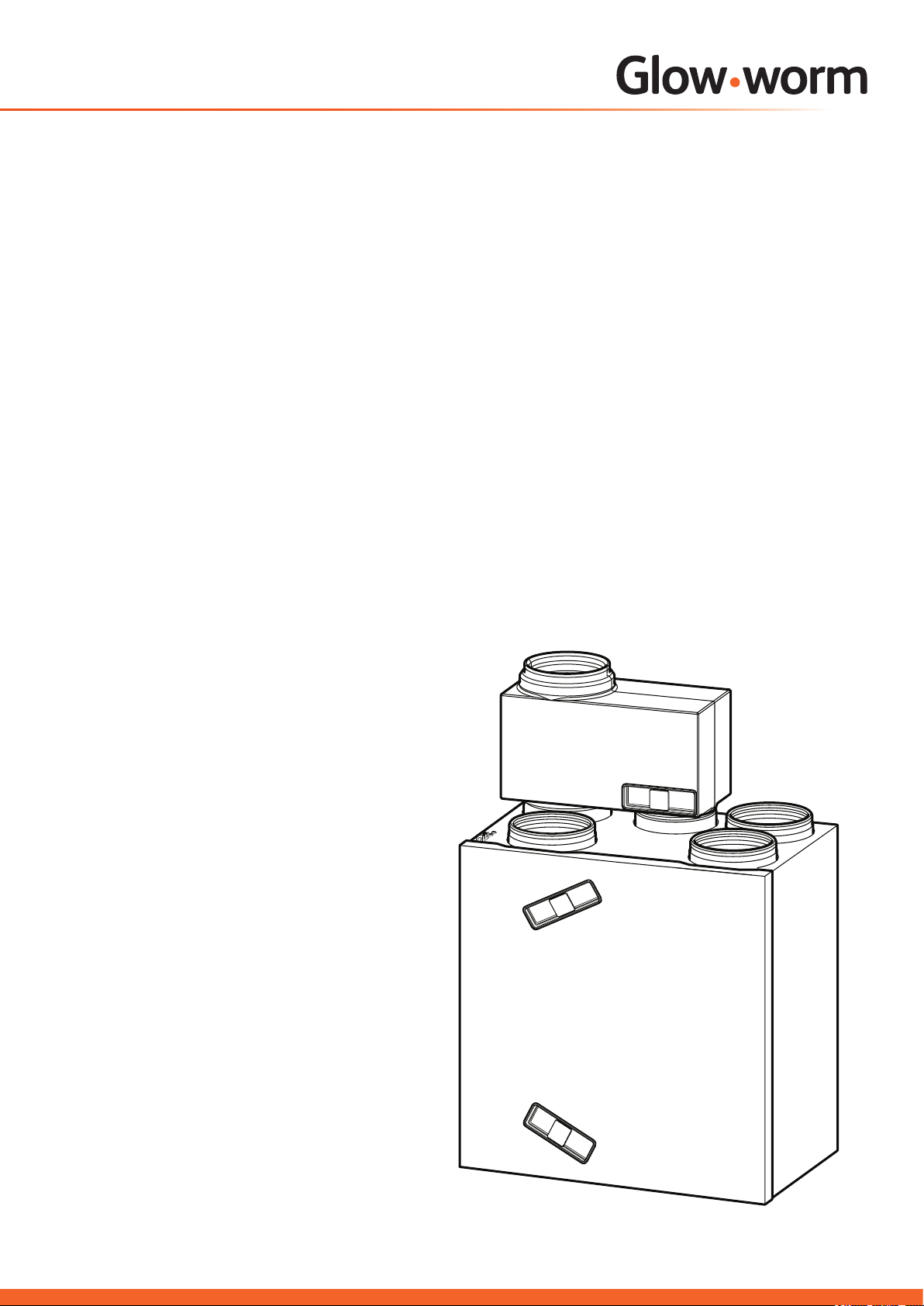
Atmosorb
Installation and Servicing
Instructions
HRD 275
Part. No. 0010008891
HRD 350
Part. No. 0010008892
Mechanical Ventilation
system with heat recovery
www.glow-worm.co.uk
Page 2

Guarantee
Glow-Worm guarantees that the high-quality product that you have purchased is free from any manufacturing defects. This guarantee
is in addition to and does not replace nor limit your statutory rights. Your local Trading Standards ofce may advise you.
The guarantee is valid only for Glow-Worm Atmosorb Heat Recovery Products that are (1) purchased in Great Britain and Northern
Ireland and installed and put into operation by a qualied and competent installer and (2) the Atmosorb is properly serviced annually in
accordance with the manufacturer’s specications and the work is undertaken by suitably qualied and competent servicing personnel.
Proof of servicing may be requested for these purposes. In particular, the following conditions apply:
Glow-Worm provide you with a manufacturer’s guarantee of up to 2 years on this product for parts and labour only subject
to the conditions below.
The guarantee periods shall commence from the date of installation or for 2 years after manufacture whichever is the sooner.
If any material or manufacturing defects occur within the guarantee periods described above, they shall be corrected free of charge by
Glow-Worm Customer Service. Whether the Atmosorb is repaired or replaced shall be decided at the sole discretion of Glow-Worm
Customer Service. In the event of a replacement we shall be entitled to make a similar product available if the Atmosorb is no longer
produced at the time of reporting the defect.
Under no circumstances shall any replacement parts provided lead to an extension of the guarantee period.
Prior to any visit by Customer Services to your premises on the agreed date your co-operation is essential to provide the appropriate
facilities necessary for the unhindered performance of the engineer’s visit. In particular you must make provision for the appliance to
be easily accessible; any costs incurred in doing so shall be borne by you.
The guarantee is valid only for defects in materials or defects in manufacturing. In particular it is not valid for any defects that are
caused due to:
- installation by incompetent and untrained personnel;
- a defective system design, system conguration or type of installation;
- defective wiring/installation work or due to defective handling during such work;
- non-compliance with the installation and operating instructions;
- non-compliance with Glow-Worm’s servicing instructions for Atmosorb;
- unsuitable servicing and unsuitable tests;
- any issues caused by associated ductwork connected to the appliance;
If any work on the Atmosorb is not performed by either our Group Service or by a competent specialised company, the guarantee shall
lapse. This shall also apply, if the Atmosorb is connected to any parts that have not been approved by Glow-Worm.
Claims that go beyond the free-of-charge correction of defects, e.g. claims for indemnication, are not covered by the guarantee.
IMPORTANT: The purchase receipt or the installer’s invoice is valid as proof of your guarantee right in relation to Glow-Worm’s
Customer Service. For this reason please keep these documents in a safe place!
Please report any guarantee incidences to our customer service on the following telephone number: Glow-Worm Service support line:
01773 596510. Alternatively please write to the Issuer of this Guarantee at:
Glow-Worm Service
Lynx House
Nottingham Road,
Belper,
Derbyshire
DE56 1JN
Customer Service:
01773 596510
Technical Helpline:
General and Sales enquiries:
Tel. 01773 824639
Fax: 01773 820569
01773 828300
2
Page 3

These instructions consist of, Installation, Servicing, Fault Finding.
The instructions are an integral part of the unit and must, to comply with the current
Regulations, be handed to the user on completion of the installation.
CONTENTS DESCRIPTION SECTION PAGE
INTRODUCTION
INSTALLATION
MAINTENANCE
Statutory Requirements 4
Important Information 5
Technical Specication 1 6
Siting the Unit 2 10
Ducting, Controls and Condensate 3 11
Installation 4 12
Commissioning 5 18
Servicing 6 22
Fault Finding 7 24
Reports 26
3
Page 4

Statutory Requirements
IMPORTANT
Where no British Standards exists, materials and equipment
should be fit for their purpose and of suitable quality and
workmanship.The installation of this unit must be carried
out by a competent person approved at the time by the
Health and Safety Executive and in accordance with the
rules in force in the countries of destination. Manufacturer’s
instructions must not be taken as overriding statutory
requirements.
Regulations
In your own interests and that of safety, it is the Law that
ALL gas appliances are installed by a competent person
approved at the time by the Health and Safety Executive in
accordance with the current issue of these regulations.
If the system is to be operated with boilers or other gas
appliances which are dependent on the ambient air, the
ventilation must be balanced in accordance to the needs of
these appliances.
The following current laws, rules, regulation standards and
guidelines must be complied with for the installation:
• Safety instructions and regulations for low-voltage
installations EN 1010
• EST Good Practice guide 268 – Efficient ventilation of
buildings – A guide to specifiers
• Rules and regulations for air circulation in flats and
habitable areas and residential buildings EN 1087
• Rules and regulations for ventilation systems
DIN 1946
• Any pertaining rules and regulations of the local or national
building authorities
• The present instructions for installation
Related documents
The installation of the heat recovery ventilation unit and any
associated ductwork and outlets must be in accordance with
the relevant requirements of the Health and Safety Document
No. 635 (The Electricity at Work Regulations 1989), BS7671
(IEE Wiring Regulations). It should also be in accordance
with the relevant requirements of the Local Authority, Building
Regulations, The Building Regulations (Scotland), The
Building Regulations (Northern Ireland) and the relevant
recommendations of the following:
BS 5588 – Fire precautions in design construction and use in
buildings.
BSEN 13141 - Ventilation for buildings. Performance testing
of components/products for residential ventilation.
BS EN 1506 - Ventilation for buildings. Sheet metal air ducts
and ttings with circular cross-section.
BS EN 13142 - Ventilation for buildings. Components/
products for residential ventilation. Required and optional
performance characteristics.
BS EN 12236 - Ventilation for buildings. Ductwork hangers
and supports. Requirements for strength.
CE label
The CE label shows that this unit complies with the following
directives:
• Low-voltage Directive 73/23/EEC, modied with Directive
93/68/EEC
• EMC-Directive 89/336/EEC, modied by the Directive
91/263/EEC, 92/31/EEC and 93/68/EEC
Testing and Certification
This unit is tested and certicated for safety and performance.
It is, therefore, important that no alteration is made to the unit,
without permission, in writing, by Glow-worm.
Any alteration not approved by Glow-worm, could invalidate
the certication, unit warranty and may also infringe the
current issue of the statutory requirements.
Control of Substances Hazardous to
Health
Under Section 6 of The Health and Safety at Work Act
1974, we are required to provide information on substances
hazardous to health.
The adhesives and sealants used in this unit are cured and
give no known hazard in this state.
Manual Handling
With regards to the “Manual Handling Operations, 1992
Regulations”, the appliance exceeds the recommended weight
for a one man lift.
The handling of the unit will involve lifting, pushing and pulling,
the use of a sack truck may be required.
The following handling techniques and precautions should be
considered:
- Grip the unit at its base
- Be physically capable
- Use safety clothing where appropriate, e.g. gloves,
safety footwear.
Ensure safe lifting techniques are used:
- Keep back straight.
- Avoid twisting at the waist.
- Avoid upper body/top heavy bending.
- Always grip using the palm of the hand.
- Use designated hand holds.
- Keep load as close to body as possible.
- Always use assistance if required.
Electrical Supply
The unit MUST be earthed. All system components shall be
of an approved type and all wiring to current I.E.E. wiring
regulations. External wiring must be correctly earthed,
polarised and in accordance with the relevant standards.
In GB, this is BS 7671.
In IE, this is the current edition of ETCI rules.
The unit MUST be connected to a permanent 230V ac, 50Hz
supply. Connection of the whole electrical system of the
unit, including any controls, to the electrical supply MUST
be through one common isolator and must be fused 3 Amp
maximum. Isolation should be by a double pole switched
fused spur box, with a minimum gap of 3mm for both poles.
The fused spur box should be readily accessible and
preferably adjacent to the appliance. It should be identied as
to its use. Alternatively connection can be made through an
unswitched shuttered socket and 3A fused 3-pin plug both to
the current issue of BS 1363, provided they are not used in
a room containing a bath or shower.
Wiring to the boiler must be PVC 85OC insulated cable, not
less than 0.75mm2 (24/0.20mm).
4
Page 5

Important Information
Notes on the documentation
The following notes serve as a guide for the entire
documentation. Further documents apply in combination with
this installation instructions. We accept no liability for any
damage caused by non-observance of these instructions.
Documentation Storage
Give this installation manual and all accompanying
documents to the operator who will store them so that they
are available when required.
Manual Validity
This installation manual is exclusively for the appliances:
Atmosorb HRD 275 part number 0010008891
Atmosorb HRD 350 part number 0010008892
For the part number of your unit, refer to the data plate
positioned on the underside of the bottom panel.
Intended Use
The Atmosorb is a wall-mounted ventilation system with heat
recovery.
The unit is connected to an air ducting system, which is
equipped with silencers, pre-lters, fresh-air and exhaust-air
grilles and louvres.
Fresh air grilles supply fresh air to the living areas and stale
moist air is extracted from the kitchen, bathroom and WC.
An optional bypass is available for summer operation, it can
directly provide living rooms with cool external air whenever
it is necessary. The external air ow bypasses the heat
exchanger.
With the digital remote control the user is able to automatically
switch and adapt the units power to suit their own
requirements.
The unit ensures:
• A constant air exchange in the building.
• The hygienic minimum air exchange in accordance with UK
building regulations Part F.
• Energy savings thanks to high efciency heat recovery.
• A high hygiene standard due to the prevention of humidity
and mould damages of the building.
Safety Instructions
The Atmosorb ventilation units are built and designed
according to accepted safety rules and regulations.
Nevertheless, there is still a risk of injury or death to the user
or others or of damage to the unit and other property in the
event of improper use or use for which it is not intended.
The unit must be installed by a competant person, who is
responsible for the observance of the current regulations,
rules and guidelines.
The remote control including the operating mode selector
and the timer must only be used for controlling the unit as
described in these instructions; it is not designed for any other
purpose.
Due to high level of dust, operation during any construction
phase is not allowed.
Any other or additional use is considered to be improper.
The unit is not suitable for ventilating swimming pools.
The manufacturer/supplier shall not be responsible for any
damages resulting from such improper use.
The user alone bears the risk.
Intended use includes the observance of the operating and
installation manual and all other applicable documents,
as well as adherence to the maintenance and inspection
conditions Installation of the device can be only carried out by
a competent person approved at the time by the Health and
Safety Executive and will be responsible for the changes in
the air ow adjustment.
This unit should only be used in conjunction with a propriety
ductwork system installed in accordance with HVCA guide
DW144 (steel ductwork) & DW154 (plastic ductwork).
The unit is equipped with a frost protecting sensor.
This sensor measures the temperature of the discharge
air. The fresh air fan is switched off if the discharge air
temperature falls below 3°C.
Once switched off, the fresh air fan is only switched on again
when the discharge air temperature has risen above 8 °C.
If the protection circuit is activated against the low pressure
(STOV, see section 5.1.1), the frost protection sensor switches
both ventilators off.
The outside air ow may be much cooler than the temperature
of the discharge air measured by the frost protection sensor
before the anti-freeze monitoring device is activated. Its
operation is possible up to -7 °C outside temperature.
Manufacturer’s Warranty and Liability
Glow-worm warrants that this product is free from defects of
manufacture.
It is covered by a manufacturer’s warranty of 24 months. The
aforesaid manufacturer’s warranty shall be applied in addition
to any legal warranty cover and shall not replace or restrict
your legal claims under the Sale of Goods Act. This warranty
shall become effective from the day of installation, or 2 years
after the manufacture of this system whichever is soonest.
This warranty shall be applicable only for such appliances
which have been installed in UK by a competent installer.
If on the rare occasion that material or fabrication defects
arise during the warranty period, the Glow-worm Customer
Service will repair these defects free of charge. It shall be at
the sole discretion of the manufacturer’s Customer Service
if he is to repair a defective unit or to replace it. Work under
warranty shall never cause an extension of the warranty
period.
This warranty shall only cover material or manufacturing
defects. The warranty shall not be applicable to such faults or
defects caused due to improper installation, commissioning,
handling and use, insufcient maintenance or intervention by
unauthorised persons. The warranty shall become void if such
work is executed to the appliance by other persons than those
belonging to our customer service or an authorised installer.
The aforesaid shall apply as well if parts or components are
incorporated in the unit or if the unit is connected to parts or
components which have not been approved and certied by
Glow-worm. Furthermore, the aforesaid warranty shall not be
applicable to such claims exceeding the elimination of defects
and faults free of charge, e.g. claims for damages.
Please call our service number 01773 596510 to report any
defects under warranty.
Service and Maintenance
To ensure regular servicing, it is strongly recommended
that arrangements are made for a Maintenance Agreement.
Please contact Glow-worm Aftersales Service (01773 596510)
for further details.
Spare Parts
Remember, when replacing a part on this appliance, use
only spare parts that you can be assured conform to the
safety and performance specication that we require. Do not
use reconditioned or copy parts that have not been clearly
authorised by Glow-worm.
If a part is required contact Glow-worm’s own service
organisation using the telephone number on the inside front
cover of this booklet.
5
Page 6
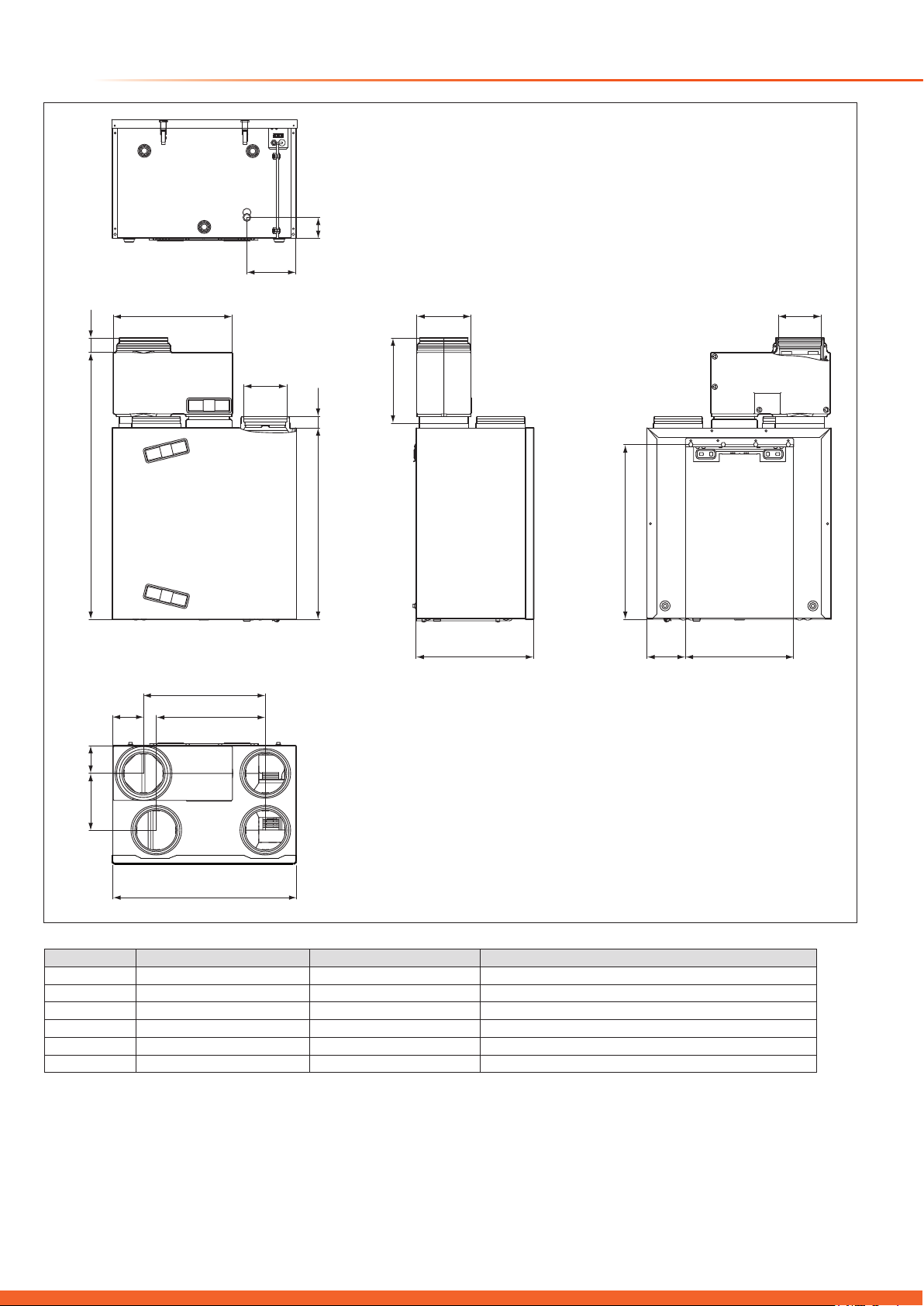
1 Technical Specication
A
77
127
B
471
521
D
ø 150/ø 160/ø 178/ø 198
ø 150/ø 160/ø 178/ø 198
Pipe diameter to be selected for the bypass connection
A14
18 2
18 2
14882
53EF
986
115
4 4 1
Y-Y
450
4 0 3
ØC (4 x)
709
315
200
D
6 4 5
B
14 2 400
680
Atmosorb HRD 275 Atmosorb HRD 350 Remarks
C ø 150/ø 160/ø 178 ø 180/ø 198 Pipe diameter to be selected for all 4 air connections
A 102 122
F 210 240
6
Overall Dimensions
Page 7

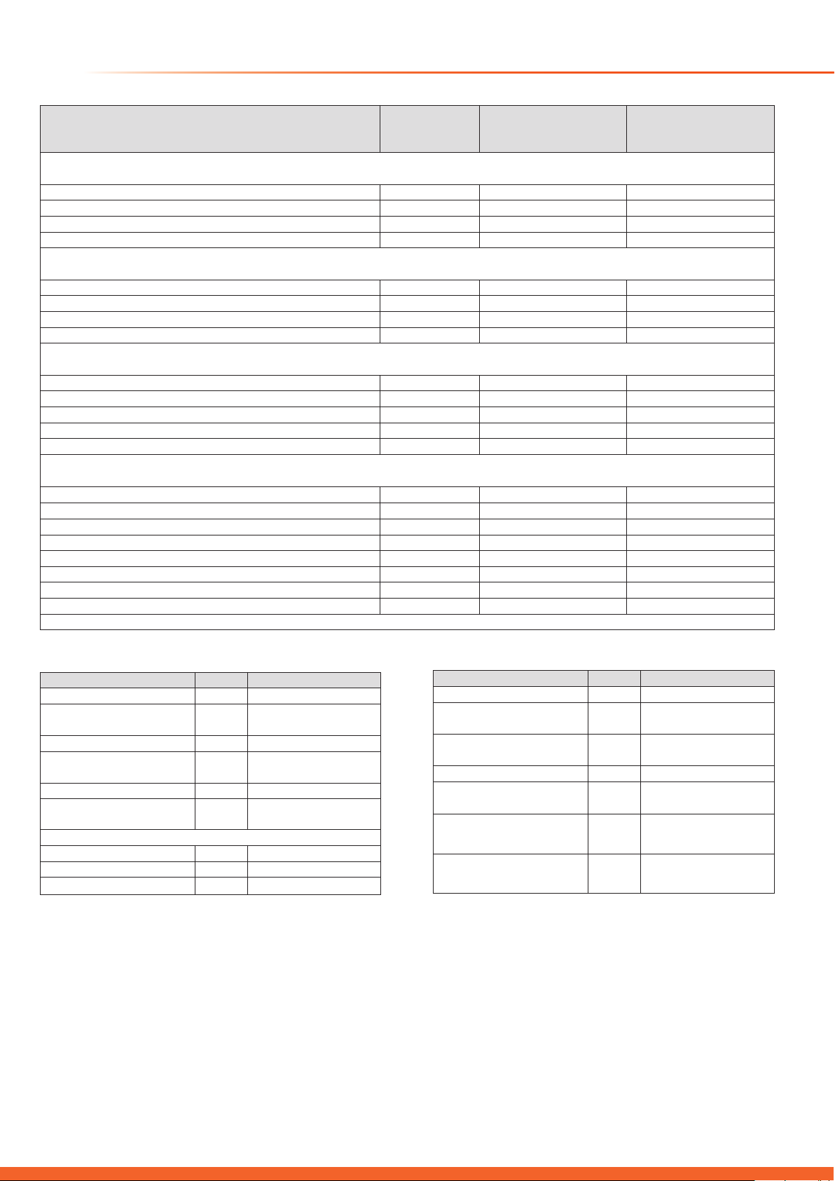
1 Technical Specication
P
210 W
Maximum electrical power consumption
T
Max
60 °C
Maximum operating temperature
1.1 Data Label - Atmosorb
The identification plate is positioned below the unit.
The indications given on the identification plate have the
following meaning:
Units Value Description
230 V ~50 Hz Mains voltage
max
V
dP
275 m3/h Maximum air volume flow
max
170 Pa allowable pressure loss of the device
max
at V
Max
For further information please read section “Technical Data”
Serial-no. 1234567890xxxxxx
HRD 275
230V~ 50 HZ
P
V
dP
T
Max
Max
Max.
210 W
275 m³ / h
170 Pa
Max
60 °C
1.2 Data Label - Bypass
You can find the identification plate on the top of the device.
The indications given on the identification plate have the
following meaning:
Units Value Description
12 V DC Voltage supply
P
3 W Maximum electrical power consumption
max
Serial-no. 1234567890xxxxxx
Bypass HRD 275 - HRD 350
12 V DC
P
3 W
Max
IPX2
Bar – Code
IPX2
nur zu verwenden mit Atmosorb HRD 275 / 350
only to use with Atmosorb HRD 275 / 350
alleen te gebruiken met Atmosorb HRD 275 / 350
utiliser seulement avec le Atmosorb HRD 275 / 350
Kan kun bruges sammen med Atmosorb HRD 275/350
Bar – Code
7
Page 8
1 Technical Specication
Feed pressure at max. volume flow
Pa
170
265
Frost protection mode active
°C-7-7
Dimensions height x length x depth
mm
709 x 680 x 471
709 x 680 x 521
Weight (gross)
kg4751
Heat exchanger material
Aluminium
Aluminium
Acoustic power
db(A)4852
Power consumption at 30 % of max. air volume flow
W
21 (83 m3/h, 15Pa)
30 (105 m3/h, 24Pa)
Minimum power consumption
W2130
Maximum power consumption
W
210
350
Protection class
IP X2
IP X2
* Standard Assessment Procedure (SAP)
Operating voltage Umax
V
24
Current consumption
mA
< 17
Level of protection
IP
20
Dimensions
Depth
mm
40
Voltage supply
V DC
12
Maximum ambient tempera-
°C
40
Minimum ambient tempera-
°C
5
Protection class for controller
IP X2
Air connections
mm
Diameter 150, diameter
Description Units Atmosorb HRD 275 Atmosorb HRD 350
Air specifications
Maximum air volume flow m
3
/h 275 350
Filter class EU/G 3 3
Filter surface area m
Thermal specifications
Thermal efficiency as per SAP* % 90,5 < 90
Maximum ambient temperature °C 40 40
Minimum ambient temperature °C 5 5
Mechanical specifications
Air connections mm ø 150, ø 160 and ø 180 ø 180 and ø 200
Electric specifications
Voltage supply V/Hz 230/50 230/50
Power consumption at 60 % of max. air volume flow W 55 (165 m3/h, 61Pa) 85 (165 m3/h, 61Pa)
Power consumption at max. air volume flow W 175 (275 m
Maximum current consumption A 0,77 1,29
2
0,25 0,25
3
/h, 170Pa) 295 (350 m3/h, 265Pa)
Remote Control Bypass
Description Units
Permitted ambient temperature
Minimum cross-section of the
connection lines
Protection class for
controller
Height mm 97
Width mm 146
°C 40
2
mm
0,75
III
ture
ture
Current consumption mA 200
Dimensions height x length x
depth
Description Units
mm
315 x 441 x 200
160, diameter 180,
diameter 200
8
Page 9
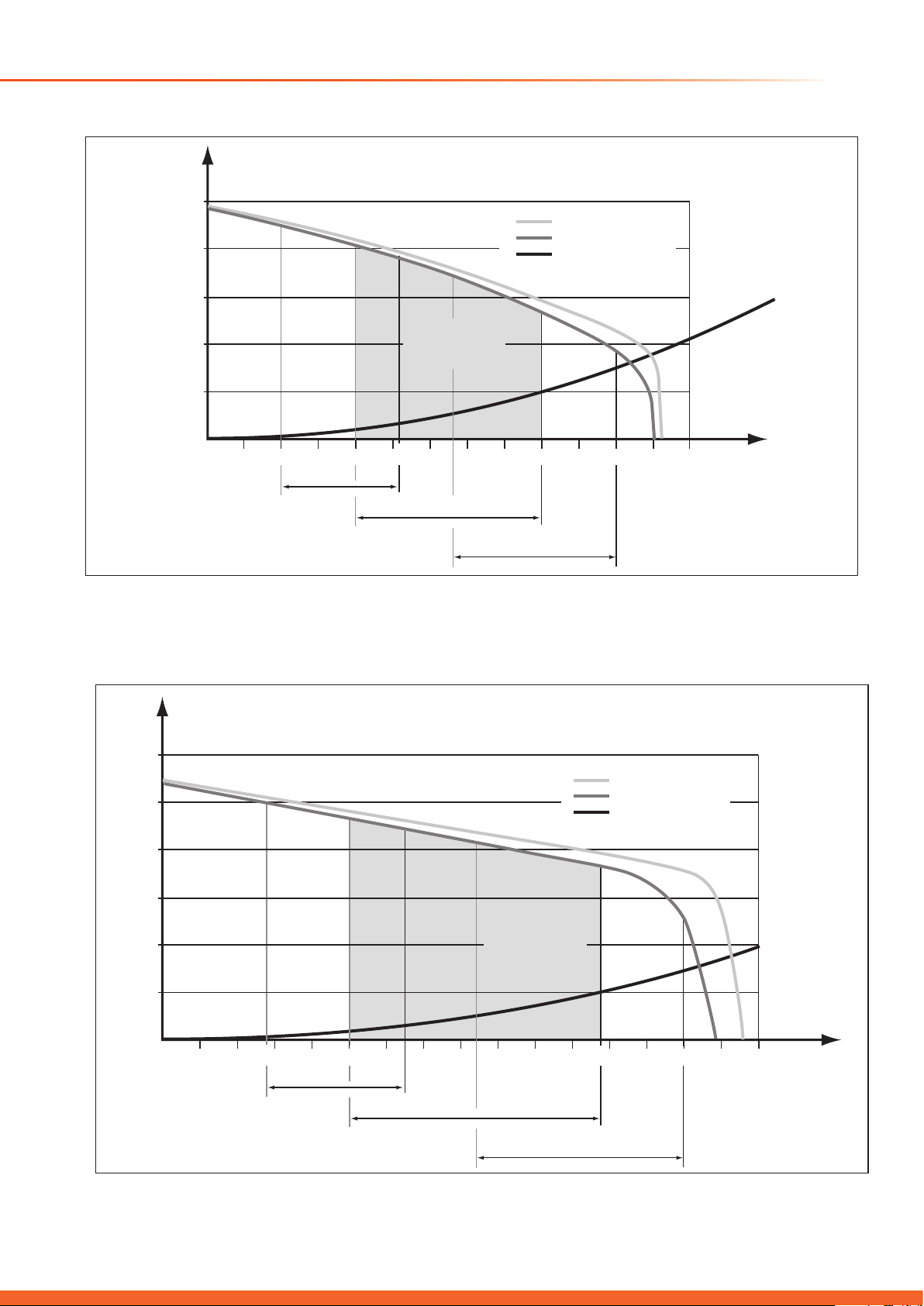
1 Technical Specication - Fan Curves
Performance Diagrams
[Pa]
500
400
300
200
100
Exhaust air
Fresh air
System
characteristic
Recommended
design range
Air 2
Atmosorb HRD 275
[Pa]
600
500
400
0
0 25 50 75 100 125 150 175 200 225 250 275 300 325
Air 1
Air 2
High
Exhaust air
Fresh air
System
characteristic
[m
3
/h]
300
200
100
0
0 25 50 75 100 125 150 175 200 225 250 275 300 325 350 375 400
Atmosorb HRD 350
Air 1
Air 2
Recommended
design range
Air 2
High
[m
3
/h]
9
Page 10
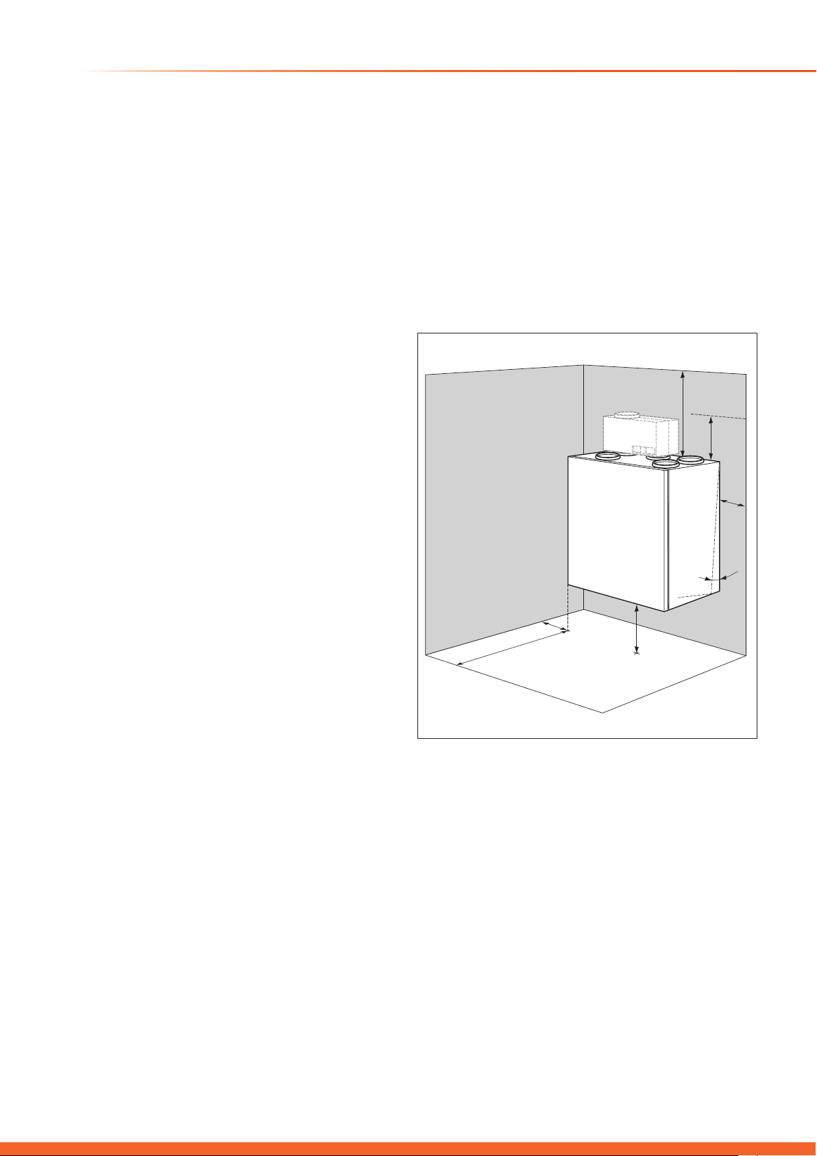
2 Siting the Unit
1000
100 300
100
300
0-1˚
600
2.1 Site Requirements
The site for the unit must be dry and frost-free. The system
installation must be planned in detail, with particular attention
to the positioning of the fresh air and exhaust air ducts and to
include sufficient sound insulation.
NOTE: The temperature of the unit can be considerably lower
than the temperature of the room, it is being installed in. To
avoid undesirable accumulation of condensate, the circulation
of fresh and exhaust air must be provided in the room.
The unit is wall-mounted and should preferably be close to a
drain outlet for the condensation drain.
• The unit must be installed with due consideration of the
requirement for adequate and practical air ducting and
services (fresh air and exhaust air, electrical power). Ensure
enough space is provided on top of the unit and at its sides to
be able to mount the required air ducts, additional silencers
and bypass unit, see diagram 2.1.
• The installation site must be selected so that the ductwork
distances to and from the unit are as short as possible.
• The wall to which the unit is to be mounted must be of a
sufficient load-carrying capacity for the weight.
• It is possible that the supplied fixing are not suitable for the
installation wall, then it is the responsibility of the installer to
provide the fixings.
• The condensate drain must be connected with the supplied
condensate drain trap and to the water outlet with an odour
trap (siphon).
• If the unit is mounted on an internal wall, do not select
a location directly above bedrooms due to possible sound
transfer. Always choose a location above a non-occupied
room such as a hall or bathroom.
• With wood-joist ceilings or similar you can provide additional
sound insulation by adding insulation between the joists.
• Always ensure that the condensate drain is free running.
• To avoid annoyance by excessive noise select a sound-
absorbing hose for final connections from the unit to the air
outlets.
• Install a silencer. This will help to neutralise possible noise
transmission between the unit and the air ducting and reduce
annoyance by noise.
• Keep the air supply inlet at a sufficient distance from
discharge air, exhaust air and drain ventilation. Comply with
the legal building rules and regulations.
• When installing the fresh air input and discharge air ducts
you will have to ensure sufficient separation to avoid that the
discharged air being re-circulated into the fresh air input.
To avoid re-circulation, the minimum recommended distance
between supply and extract is 2 metres.
2.3 Remote Control
• The remote control must be mounted such that there is
enough space around it to complete the electric wiring as well
as easy operation of the control.
• The remote control must be installed inside the living space
and be easily accessible. For further details see section
“Installation - Controls”.
2.4 Atmosorb
• Electrical connection above mains voltage socket with
230 V 50 Hz mains voltage.
The connection must comply with the current rules and
regulations.
14880
Diagram 2.1
2.2 Installation Minimum Clearances
• Please refer to diagram 2.1.
• For the installation, at least 100mm of free space on the
side of the device must be provided.
• For installation, filter replacement and maintenance works,
1 m working space in front of the ventilation unit is needed.
Over and beneath the device at least 30 cm are required.
10
Page 11

3 Ducting, Controls and Condensate
3.1 Ducting connections
Refer to diagram 3.3.
• Atmosorb HRD 275: 4 x air duct connections ø 150 mm, or
alternative ø 160 mm and ø 180 mm
• Atmosorb HRD 350: 4 x air duct connections ø 180 mm, or
alternative ø 200 mm
3.2 Bypass(Optional)
Refer to diagram 3.2.
• Atmosorb HRD 275 and HRD 350: 4 x air duct connections
ø 150 mm, or alternative ø 160 mm and ø 180 mm.
BYPASS CONNECTION
EXTERNAL AIR INLET
AIR EXHAUST
3.3 Remote Control
• Control cable from the remote control to the unit is a 2-core
cable, with cross-section 0,75 mm2. Maximum cable length
300m.
The connection must comply with the current rules and
regulations.
3.4 Condensate Drain Trap
The condensate drain trap must be connected to the threaded
tube under the unit. Additionally, an odour trap is required in
the waste water system. For hygienic reasons, between the
drain traps an air gap of at least 20 mm must be provided.
• Condensed water drain G 3/4 connection for the condensate
drain trap.
• The attached condensed water drain trap is designed to
compensate pressure between the device and the installation
room, for that reason it must always be filled with clear water.
EXTERNAL AIR OUTLET
14879
FRESH AIR OUTLET
(TO ROOM)
EXHAUST AIR FILTER
HEAT EXCHANGER
EXTERNAL AIR FILTER
AIR INLET FROM
OUTSIDE
FILTER
14881
14878
FAN
CIRCUIT BOARD
FAN EXHAUST
CONDENSATE DRAIN
OUTLET
3 STAGE SWITCH
CONNECTION
1 Outside air
2 Exhaust air (from living room)
1
3 Fresh air (to living room)
4 Outgoing air (to outside)
Diagram 3.1
VENTILATION FLAP
Diagram 3.2
2
4
3
Diagram 3.3
11
Page 12

4 Installation
4.1 Contents of Pack
• Digital remote control
• Mounting set consisting of:
• Fixing brackets 405 x 60 mm
• Condensate drain trap
Accessories (optional)
• Bypass Atmosorb
• Filtersets H.E. F6
Ensure that the wall offers the appropriate load carrying
capacity and that appropriate fixing are used to secure the
unit. It is possible that the attached mounting set with the
fixing screws and wall plug is not suitable for every wall.
The ventilation unit weighs about 35 kg. When hooking the
unit onto the fixing bracket, never lift the unit alone.
NOTE: This unit is solely intended for vertical wall mounting.
When mounting the system it is absolutely necessary to
ensure the horizontal positioning of the ventilation unit and an
angle of > 0° and < 1° in vertical position to ensure that the
condensation water can easily flow out of the unit.
• Atmosorb unit
4.2 Installation of the Unit
With due regards to the minimum clearances, condensate
drain position and ducting, mark and drill the position for the
wall bracket securing screws, see diagram 4.1.
Secure the wall bracket with suitable wall fixings.
Mount the unit, by hooking over the wall bracket, see diagram
4.1.
WALL MOUNTING
BRACKET
945 min
300 min
clearance
0-1˚
Diagram 4.1
14883
15530
4.3 Connection of the Condensate Drain
Fit the connecting piece for the condensate drain trap to the
connection outlet on the bottom of the unit.
Connect the attached condensate drain trap with the
connection piece, see diagram 4.2.
IMPORTANT: For the condensate discharge of the unit a
second drain trap is required, see diagram 4.3.
For hygienic reasons, the condensate drain trap must not be
directly connected to the waste water system.
An air gap of at least 20 mm must be provided. A wrongly
installed condensate outlet can lead to condensate
accumulation and to an uncontrollable escape of condensate.
Use of the customer service and possible subsequent
damages are not covered by the Glow-worm warranty.
CONNECTING
PIECE AND
WASHER
CONDENSATE
DRAIN OUTLET
CONDENSATE
DRAIN TRAP
Diagram 4.2
12
Page 13

4 Installation
4.4 Air Duct Connections
Before executing the final connection check the air ducts are
still clean. If necessary, clean the air ducts.
Only then connect the air ducts to the unit.
Connect the air ducts to the connections on top of the unit.
NOTE: Air ducts must be tightly connected to the unit - use
suitable accessories or sealing material. Insulation of the
fresh air and outgoing air ducts must be diffusion resistant.
4.5 Opening and Closing the Unit
The unit is equipped with a fixed front panel. For mounting
and maintenance work on the unit it is necessary to remove
the front panel.
IMPORTANT: Switch off the mains supply to the unit before
starting to work.
Remove the filters from the Atmosorb first, to enable removal
of the front panel.
Pull both filters out of the unit, see diagram 4.4
Remove the screw from the LH toggle-type fastener below the
unit.
Then open both toggle-type fasteners.
Pull the lower part of the front panel towards you.
Now lift the front panel above the top fixing points.
To close the unit, carry out the steps in reverse order.
IMPORTANT: Always ensure the screw is replaced into the
left hand toggle after re-assembly to avoid unauthorised
access to the unit.
14885
a
a
airVENT
> 2 cm
airVENT airVENT
Diagram 4.3
b
c
e
d
Diagram 4.4
13
Page 14

4 Installation - Bypass (Optional)
4.6 Mounting and Electrical Connection
of the Bypass (optional)
IMPORTANT: Switch off the mains supply to the unit before
starting to work.
Improper electric installation may cause accidents. Therefore
it is absolutely mandatory to have a competent person
approved at the time by the Health and Safety Executive to
complete the electrical installation.
NOTE: The bypass electrical connection must be completed
before mounting.
Open the unit as previously described.
Remove the plug from the middle air connection by pushing it
upwards from the inside, see diagram 4.5.
Inside the bypass air connection in the unit, there is a 10-pole
connector to which the bypass plug is connected.
You will find a plug in the bag in the casing wall. Pull the plug
out of the bag of the casing wall.
Release the cable with the 10-pin connector from the casing
wall and connect the bypass plug with the connector.
To install the temperature sensor, proceed as follows, refer to
diagram 4.5.
Remove the plug from the sensor hole in the outside air duct.
Push the temperature sensor through the hole into the
exhaust air duct.
NOTE: To ensure the correct bypass function the temperature
sensor must project at least 25 mm into the exhaust air flow.
14886
TEMPERATURE
SENSOR
25mm
ELECTRICAL
PLUG
Diagram 4.5
After completing the electrical connection of the bypass, you
can mount the bypass unit.
Push the bypass into or over the both outside air connections
of the unit.
Make sure that the filter unit is aligned towards you.
Check that the bypass is completely inserted.
Plug in the mains plug into the plug socket.
14886
Diagram 4.6
14
Page 15

4 Installation - Controls
4.7 Installation of the Remote Control
Site the remote control on an inside wall at a height of about
1.5 m, were the controller is able to detect the circulating
ambient air clearly and unimpeded from furniture, curtains or
other external influences. The position should be selected so
that neither air drafts from the door or the window nor heat
sources such as radiators, TV or solar irradiation may directly
influence the controller.
A connection with the ventilation unit is established via a
2-core connection cable.
Pull the remote control from the wall base.
Refer to diagram 4.7.
With due regard to the position of the cable entry, mark the
wall base securing points on the wall. Using a 6mm diameter
drill and fixings supplied, secure the wall base to the wall
having first pulled the cable through the cable entry.
Connect the cable to the corresponding terminals (eBUS “+”
and “-”) on the terminal connecting strip.
Place the control on to the wall base such that the pins at the
back of the upper part locate into the seats.
Press the casing to the wall base till it locates, taking care not
to bend the controller connection pins. Make sure that you do
not bend the contacts.
15544
TERMINAL
STRIP
WALL BASE
CONTROL
CASING
SECURING
POINT
4.8 Electrical Connection of the Remote
Control
IMPORTANT: Switch off the mains supply to the unit before
starting to work.
To prevent accidents, electric installation can only be carried
out by a competent person approved at the time by the
Health and Safety Executive.
The remote control is connected to the ventilation unit via
a two-core cable. Communication is via a 2-pole eBUS.
The eBUS connector is sized to accommodate wiring of 2 x
0.75 mm2 (recommended). It is possible to interchange the
connections without affecting communication. This connection
is at the bottom of the unit.
Connect the control cable as shown in diagram 4.8, to the
eBUS-clamps + and -.
SECURING
POINT
eBUS
CONNECTION
15543
Diagram 4.7
15545
VIEW ON UNDERSIDE OF UNIT
Diagram 4.8
15
Page 16

4 Installation - Controls
1 ("0")
Control system with remote
0↓ open
3 ("H")
HIGH position
0↓ connected to H↑
4.9 Establishment of Electrical Connection
of the 3-stage Switch (optional)
In addition to the standard control unit, you can also use
a universal 3-stage switch, routed into X12 of the PCB, to
control the ventilation unit. This must be potential-free (no
voltage), see diagram 4.9.
Connect as shown in diagram 4.10 to the clamps „0↓”, “D↑”
and “H↑”.
The following switch positions are possible:
Position Function Electrical contact
control
2 ("D") Day position (fans stage 2) 0↓ connected to D↑
(fans stage 3)
Mains connection
BUS connection
Switch 2
Switch 1
0 - 10 V Control
signal (analog)
Alarm input
Alarm output
X 15
X 16
230 V~
F4
2AT
Bus
Switch 2
Switch 1
Analog
Error In Err. Out
PC
connection
X 1X 9
white whitewhite
N L
N L N L
Freh air fan
Exhaust air fan
X 2
Control signal
X 3
X 4
X 5
0 - 10 V
Hz
Gnd
Control signal
0 - 10 V
Hz
Gnd
Temperature sensor EAO
ϑ
(Frost protection sensor)
Bypass Motor
M
ϑ
Temperature sensor EAI
ϑ
Temperature sensor SAO
ϑ
Temperature sensor SAI
- + 1 2 1 2D OH
red blue white
X 10
D OH
X 11
white white white
X 12
-
X 13
+
10
white
X 14
X 17
9
5
4
8
3
7
2
6
1
X 6
X 7
16
X 8
Diagram 4.9
Page 17

Installation - Controls
4.10 Alarm Input (optional)
The alarm input (connection „X 14“ on the board) is bridged
when the unit is delivered. If the connection is undone with an
external potential-free switching contact (break contact), both
fans will be switched off. On the display of the remote control
you will see the message “LOCK“.
IMPORTANT: Disconnect from the mains electricity supply
before starting to work on the unit.
Remove the unit front panel as described previously.
Now place the 2-core cable (minimum 0.35 mm2) in the
respective cable routing to the PCB.
Connect the lines to the connection “X 14” (alarm input) in
accordance with diagram 4.9 “Wiring scheme”.
When the contact is opened, the word “LOCK”
NOTE:
appears on the display of the remote control.
The fans on the domestic ventilation unit are then switched
off.
4.11 Alarm Output (optional)
The alarm output (connection „X 16“ on the board) is made of
a potential-free switching contact with a resistive load (Ohm)
of maximum 2 A.
4.12 Removal of cable insulation
Remove the cable insulation as shown in diagram 4.11.
Lead the cable through the strain relief, see diagram 4.8 and
screw them together.
An alarm will be triggered:
• If the time set for the filter replacement has expired. The
duration is set under the installer level option on the remote
control.
• If one of the error messages described in fault finding
section, is indicated in the remote control display.
Disconnect from the mains electricity supply.
Remove the unit front panel as described previously.
Now place the 2-core cable (minimum 0.35 mm2) in the
respective cable routing to the PCB.
Connect the lines to the connection “X 16” (alarm output) in
accordance with diagram 4.9 “Wiring scheme”.
15531
0 D
0
H
Switch
D
BUS
-
H
+
0
D
H
40 mm
Ø 4,5 - 10 mm
Diagram 4.10
Diagram 4.11
17
Page 18

5 Commissioning
5.1 Function checks
Once all connections are correctly installed in accordance
with the wiring scheme, check the functions of the remote
control, the ventilation unit and the bypass. When doing so,
note that the unit must not be started until all ventilation ducts
are connected to the unit and the unit and all ductwork are
completely sealed.
In the user sections of the “Instructions for Use” manual you
will find in detail all the settings for the individual operating
modes and the special functions. For testing functions
proceed as follows:
• Select the “night” operating mode and check that the fans in
the domestic ventilation unit are operating at low output.
• Select the “day” operating mode and check that the fans in
the domestic ventilation unit are operating at medium output
(AIR2).
• Activate the special function”advance”. Check that the
fans in the domestic ventilation unit are operating at medium
output (AIR2).
• If the output stages are not correctly switched, you must
check the wiring on the terminals of the remote control and
the domestic ventilation unit.
5.2 Start-Up
The start-up and the operation of the unit as well as
instruction to the user must be done by a competent person
approved at the time by the Health and Safety Executive.
Please note that the device can only be started up if all
ventilation pipes of the device are connected and the entire
device is closed.
As part of the start-up it is necessary to adjust the ventilation
unit.
The ventilation units are delivered with basic setting for both
fans. As each fresh air and exhaust air installation is different
and thus offers different external resistance in the air ducting
you will have to separately adjust the fresh air and the
exhaust air fan to suit.
You can adjust the domestic ventilation unit using the remote
control. Below are the necessary steps.
5.3 Adjustment of the Digital Remote
Control
To optimally match the system parameters to the required
conditions it is necessary to set these parameters with the
remote control, see diagram 5.1. The system parameters are
located in an upper operation level and should only be set by
a competent person approved at the time by the Health and
Safety Executive.
5.4 Expert Technician Level
Hold down the “mode” button for about 10 seconds to go to
the installer level. The symbol appears on the display.
Then, by pressing the dial, it is possible to select the
functions. The functions shown in table 5.1 can be scrolled
through one after the other.
To change the parameters just press “prog”.
If you want to return to the basic display, shortly press the
“mode” button.
The adjustable air volume flows apply jointly to fresh air and
exhaust air.
15541
18
Diagram 5.1
Page 19

5 Commissioning
Min m3/h
50
70
Max m3/h
AIR2
AIR2
Atmosorb HRD
275
350
press
Atmosorb HRD
275
350
Default setting m3/h
275
350
Max m3/h
325
400
Must value of the volume flow after the activati-
press
AIR5
Min. volume flow with activated
bypass
Atmosorb HRD
275
350
Min m3/h
AIR1
AIR1
Max m3/h
HIGH
HIGH
press
Atmosorb HRD
275
350
Factory setting
OFF
OFF
ON = If one fan fails, the other fan is also de-
press
FILT
Days till the next filter replacement
Default setting/days
180
180
Max. days
180
180
press
POL1
No function
Please refer to diagram 5.1 for control panel buttons and layout:
Action
press
mode
button
for 10
secs
press
prog
button
Display
AIR1
AIR2
Meaning
Set volume flow night
1st stage
Atmosorb HRD 275 350
Default setting m
Set volume flow for the
non-programmed periods.
Set volume flow day
2nd stage
Default setting m3/h 165 210
Min m
Max m
Set volume flow for the programmed periods.
Table 5.1 Installer level
3
/h 80 105
3
/h AIR1 AIR1
3
/h HIGH HIGH
Action
prog
button
press
prog
button
prog
button
prog
button
Display Meaning
HIGH Set volume flow, 3rd stage
Min m3/h AIR2 AIR2
on of the special function "Advance Mode" with
the key F.
AIR4 Set volume flow holiday
Atmosorb HRD 275 350
3
Default setting m
3
Min m
/h 50 70
3
/h AIR2 AIR2
Max m
Set volume flow after activation of the special
function "holidays" with the F button, additionally in "OFF" mode.
Default setting m3/h 110 140
Minimum volume flow when the connected bypass switches to summer mode (without heat
recovery).
STOV Protective switching against
negative pressure
/h 60 75
activated.
This protective switching prevents negative
pressure as a result of only disconnecting the
supply fan. If the protective switching against
the low pressure is activated, both fans are
switched off by the frost protection function.
prog
button
prog
POL2
Atmosorb HRD 275 350
Min. days 30 30
Adjusted in 30 day steps to which the indication "FILT" is shown on the remote control display. (Alarm output is closed)
button
Table 5.1 Installer level (continued)
19
Page 20

5 Commissioning
press
C-AIR
Set volume flow correction
Default setting in %
0
0
Adjustment of the set volume flow for fresh air
Factory setting in °C
0
0
Min in °C
-3
-3
Correction of the room temperature indicated on
Factory setting
0
0
press
MON
Desired value of the current month*
Factory setting
01
01
press
YEAR
Desired value of the current year*
Atmosorb HRD
275
350
Max/year
2159
2159
* Setting will be required if the automatic switching from
summer to winter time is to be activated.
5.5 Service/Diagnostics Level
The service/diagnostics level should help the installer during
the service.
Keep the mode and prog buttons simultaneously pressed for
about 3 seconds to reach the service/diagnostics level. The
display will show the symbols .
By pressing and holding the “mode” button you will return to
the basic display.
You can display the following functions / information:
Action Display Meaning
prog
button
press
prog
button
press
prog
button
prog
C-RT Room temperature correction
DAY Desired value of the current day*
Atmosorb HRD 275 350
Min in % -50 -50
Max in % +50 +50
in order to produce a slightly negative pressure
in the building. At low temperatures it prevents
ice formation due to condensation water on the
doors and windows.
Atmosorb HRD 275 350
Max in °C +3 +3
the display of the remote control.
Atmosorb HRD 275 350
Min 0 0
Max 31 31
Atmosorb HRD 275 350
button
Min/month 01 01
Max/month 12 12
prog
button
Factory setting 2005 2005
Min/year 2000 2000
Table 5.1 Installer level (continued)
Please refer to diagram 5.1 for control panel buttons and
layout:
20
Page 21

5 Commissioning
press +
press +
press +
press
AIR/
Current air volume flow indication in
press
APPL/
Display of the unit type
press
Display
Display test: All symbols of the display
press
VER1/
Display of the software version of the
press
press mode
Action Display Meaning
press mode
and prog
BYP
ON
Bypass switches to summer mode
button for 3
seconds
press +
button
press +
button
button
button
button
prog button
prog button
prog button
prog button
+ button
ALAR ONAlarm output is activated
SAO/*
xx oC
EAO/
xx oC
EAI*
xx oC
SAI/*
xx oC
xx m3/h
1 / 2
x.xx
VER2/
x.xx
(contact closed).
Display of fresh air temperature (Supply Air Out)
Display of the discharge air temperature at the frost protection sensor (Exhaust Air Out)
Display of the exhaust air temperature
(Exhaust Air In)
Display of the outside air temperature
(Supply Air In)
the ventilation unit. By turning the dial
it is possible to change the air quantity
during the test mode.
1 = Atmosorb HRD 275
2 = Atmosorb HRD 350
Turn the dial to select the unit type.
are indicated, however, not all symbols
of recoVAIR have a meaning.
remote control
Display of the software version of the
recoVAIR PCB
Return to basic display
and prog
button
5.8 Domestic Ventilation Unit Adjustment
Adjustment procedure
First of all ensure that the overall air flow calculated for the
installation is reached by the system. Then adjust the air
flow rates for the individual living spaces. Finally adjust the
individual air flow distribution within each living space.
Total Air Flow Adjustment
First adjust the desired air quantity calculated when the
system was designed with the remote control for all operating
modes (installer level). Proceed step by step as described in
table 5.1, page 19. In the table you will find the information for
the desired values.
NOTE: The planned air flow must be in the in the day mode
(2nd stage) because this is the standard operation mode.
Adjusting the air quantities at the system
1. Adjust all the exhaust and fresh air valves in the living
rooms to the middle opening of about 50 %. Then proceed in
accordance with the instructions given in the manufacturer
operating manual.
The air speed must not exceed 1.5 m/s at a distance of 50 cm
from the valve.
2. Make sure that all valves in the existing air duct manifolds
are completely opened.
3. Switch the domestic ventilation device into the operation
mode “day mode” using the remote control.
4. Measure the partial air flow at the strings with control
dampers if there are some available. Correct these settings if
required by adjusting the control dampers.
5. Open, if necessary, air inlet and air outlet valves if the
desired total air flow has not been reached.
6. Raise the ventilator revolution speed using the values in
table 5.1 if the total air flow is too low.
7. Go to the installer level in the remote control by pressing
the “mode” button for 10 seconds.
8. Press the “prog” buttons until “C-AIR” appears on the
display.
9. Correct the inlet air flow by pressing the - or + buttons until
the inlet and the outlet air volume are equal (see table 5.1).
5.9 Operator Delivery
Completely fill in the attached measurement report
(page 27) and hand it over to the operator.
Functions of the service/diagnostics level
* These values can only be called with a bypass unit installed.
Please refer to diagram 5.1 for layout of control panel buttons:
5.6 Testing of the bypass and other
functions
Go to the service/diagnostics level as described in
section 5.5. Now test successively all functions in accordance
with the above table. If the bypass is not connected or if a
sensor is defective, the display will show the “-” symbol.
5.7 Reset to the Factory Setting
• Press the “prog” button for 15 seconds to reset the controller
to the default setting.
As soon as the display lights up twice, the controller is
completely re-set to its default settings. This means that you
will have to perform all individual settings again.
21
Page 22

6 Servicing
NOTE: Replace the filters at least once a year or
after maximum 2000 operating hours. If the filters are heavily
soiled, they should be replaced at shorter intervals.
A competent person approved at the time by the Health and
Safety Executive in the area of the air pollution control, should
carry out regular inspections. The first inpection should be
performed 3 months after commissioning.
To avoid damaging the unit, the following maintenance work
must be carried out by a competent person approved at the
time by the Health and Safety Executive.
The functional operation of the ventilation unit requires it to be
serviced once per year, this includes the following:
• Check the general condition of the unit
• Remove any dirt and soiling at the unit.
• Clean or replace soiled filters.
• Clean the condensate outlet and check if the duct is free
• Clean soiled fan.
• Check the function of the unit, the remote control and the
bypass.
14885
a
a
6.1 Removing and Cleaning the Filter of the
Ventilation Unit
Open the unit and remove the filters then the front panel as
shown in diagram 6.1.
If the filters are not heavily soiled, you may clean them with a
normal vacuum cleaner.
If this is not enough, the filters must be replaced.
Cleaning the filters with water or other liquids is expressly
prohibited.
Description
Filter Atmosorb G3 0020064722
Filter Atmosorb Bypass G3 0020064723
High efficiency filter Atmosorb F6 0020064720
High efficiency filter Atmosorb Bypass F6 0020064721
Filter
class
Ordering number
b
c
e
d
Diagram 6.1
22
Page 23

6 Servicing
6.2 Cleaning the Heat Exchanger
IMPORTANT: When removing and replacing the heat
exchanger take care not to damage it.
Take care not to damage the heat exchanger fins. Any
damage will lead to premature wear in the system.
Refer to section 4.5 and open the unit and remove the filters
then the front panel.
Hold the heat exchanger with both hands at the edges
and without damaging the fins, carefully pull out the heat
exchanger, see diagram 6.2.
Clean the heat exchanger with a washing liquid with neutral
pH and lukewarm water, then rinse it again with clear
lukewarm water.
NOTE: detergents, especially acidic detergents (such as
vinegar cleaner), damage the unit.
The heat exchanger must be dry before replacement.
With the removed heat exchanger check as well if the
condensate water drain is clean, if necessary clean as
described below.
Slide the heat exchanger back into the unit. Take care that
the heat exchanger correctly fits into the guide rails at the
top and bottom of the housing and that it is not installed off
centre.
IMPORTANT: The heat exchanger must be flush with the
front side of the EPP body. A protruding heat exchanger can
cause leakages and condensate escape.
6.3 Cleaning the Condensate Drain
With the heat exchanger removed.
Unscrew the condensate drain trap from the bottom of the
unit, see diagram 4.2.
Check if the drain is free, see diagram 6.3.
Clean it if is blocked.
If required, clean any dirt in the drain pan.
Clean the condensate drain trap and fill it with clean water.
14889
Diagram 6.2
BYPASS
FILTER
14890
6.4 Cleaning or Replacing the Bypass
Filter
Bypass, if fitted.
See diagram 6.3 for the location of the bypass filter.
If the filter is not heavily soiled, you may clean it with a
normal vacuum cleaner.
If this is not enough, the filter must be replaced.
Cleaning the filter with water or other liquids is expressly
prohibited.
6.5 Test Operation and Restart
After servicing check the correct functioning of the unit:
• Check that the unit casing is correctly fitted.
• Insert the mains plug into the plug socket and start the
unit.
• Check the correct function of the unit.
• Check the correct function of the remote control.
Diagram 6.3
23
Page 24

7 Fault Finding
on the PCB.
Replace or clean ventilators, check the reason of soiling.
None or insufficient
Filters are extremely soiled.
Fan defective.
Clean the filter.
Replace the fan if necessary.
No or insufficient
Filters are extremely soiled.
Fan defective.
Clean the filter.
Replace the fan if necessary.
Bypass summer mode
Bypass function not activated or set days for
In the programming level of the remote control, set or activate
are detected at the remote control. See section 6
Fresh air too cold
Exhaust air and fresh air flows not balanced.
Adjust the unit in accordance with section 5.8.
if necessary, replace the bypass.
No fresh air or
Frost protection activated.
discharge air temperature above 3 °C.
Check the resistance of the frost protection sensor based on
other rooms
different parts of the roof.
Planned air flow not
System is not air-tight.
Seal all pipe connections properly if necessary.
Noise in the unit after
Wrong mounting of the fans.
Check the correct positioning of the fans.
7.1 Fault Finding
The faults listed below may only be rectified by a competent
person approved at the time by the Health and Safety
Executive.
The following checks should be performed before proceeding
onto specific diagnostics:
• Check the external electrical supply to the boiler is on and
a supply of 230V is present at the ‘L’ and ‘N’ terminals on
the installer interface, refer to section 11.4 for access and
diagram 14.4.
• Check the electrical installation and unit, carry out tests for
earth continuity, polarity, short circuit and resistance to earth,
using a suitable multimeter.
• Check that all external controls are on.
• Check the functional flow diagram, 14.5.
Fault Cause Remedy
The unit does not
operate
Temporary interruption of the mains voltage supply
or no supply at all. Power supply circuit breaker
tripped. Electricity disconnector was activated.
Fuse F4 in the unit is defective.
After a mains failure the unit automatically restarts once the
mains voltage is re-established. Re-set circuit breaker in mains
distribution board. Check that all cables are properly
connected and undamaged. If necessary, replace the fuse F4
Unit operation is very
loud even at the
minimum fan speed
fresh air supply
exhaust air flow
(i.e. in the bathroom
the mirror stays
fogged up)
does not work
Noise in the
condensation water
drain trap
Water dripping from
the unit
No silencers in the fresh air and exhaust air ducts.
Wrong silencers, or silencers are too short. Filters
are extremely soiled.
Ventilators are defective or heavily soiled.
Fresh air valves/grilles closed too much.
Exhaust air or fresh air ducts obstructed.
Fresh air input louvre too small.
Incorrect wiring.
Exhaust air valves closed too much.
Exhaust air or fresh air ducts obstructed.
Fresh air input louvre too small.
Incorrect wiring.
summer mode expired.
Incorrect positioning of the temperature sensor.
Flap position and/or motor for bypass defective.
Defective bypass motor wiring.
Drain trap incorrectly connected. Connect the drain in accordance with section 4.3.
Exhaust air and fresh air ducts are not vapoursealed.
Wrong flap position and bypass motor defective.
Mount additional silencers in accordance with the system
design.
Reduce the air quantity to the minimum fan stage. Clean or
replace filters.
Open the fresh air valves/grilles. Adjust the system again.
Clean the exhaust air and fresh air ducts.
Fit a larger louvre.
Check the wiring.
Open the exhaust air valves. Adjust the system again.
Clean the exhaust air and fresh air ducts.
Fit a larger louvre.
Check the wiring.
the bypass function.
Correctly position the temperature sensor.
Check the flap position and the motor and, if required, replace
them.
Check that the plug to the flap motor is correctly positioned.
Check in the Service/Diagnostics menu whether the sensors
Insulate exhaust air and fresh air ducts, make ducts air-tight or
use specially insulated pipes.
Check the flap and motor,
Clean the flap and bracket,
exhaust air (only one
fan running)
Odours from the
kitchen/WC enter into
Sound transmitted
between the rooms
reached at the start-up
replacing the fan.
24
With outside temperatures below -7 °C, correct
operation.
The frost protection sensor will not work at a
Outlets for fresh air and exhaust air are too close
to each other.
No crosstalk absorbers mounted. Additionally install crosstalk absorbers.
table, “Resistance Values of the Temperature Sensor“.
If necessary, replace the frost protection sensor.
Extend the distance between the outlets for fresh air and
exhaust air. We recommend to position these junctions in
Adjust the unit in accordance with section 5.8.
Page 25

7 Fault Finding
COM Err
Fans turn with 20% PWM
Communication error between the PCB in the
channel.
Pull the mains plug and insert it again.
error, contact Glow-worm Customer Service.
Wiring interrupted.
EAO Err
Temperature sensor discharge
Temperature sensor defective (interrupted or
Wiring interrupted.
Contact Glow-worm Customer Service.
SAO Err*
Temperature sensor fresh air
Temperature sensor defective (interrupted or
Wiring interrupted.
Contact Glow-worm Customer Service.
-20
95862
0
32510
25
10000
40
5330
Error Messages in the Remote Control
* Error message only with installed bypass
Indication
on the
display
LOCK Both fans inoperative Alarm input "X 14" opened. Check whether a separate switch is
SAI Err* Temperature sensor outside air Temperature sensor defective (interrupted or
EAI Err* Temperature sensor exhaust
SFAN Err Contact Glow-worm Customer Service.
EFAN Err Contact Glow-worm Customer Service.
FILT Check all filters for soiling. Time for programmed filter timer expired. Set the filter timer (in the installer level) to
Check/
component
air
air
Cause Remedy
unit and the remote control.
230 V eBUS line laid parallel in pipe or cable
short-circuited).
Wiring interrupted.
Temperature sensor defective (interrupted or
short-circuited).
short-circuited).
short-circuited).
If this does not help to eliminate the error,
contact Glow-worm Customer Service.
connected to "X 14". Check why the switch is
open.If this does not help to eliminate the
Contact Glow-worm Customer Service.
Contact Glow-worm Customer Service.
RESET.
Resistance Values of the Temperature
Sensor
Temperature in oC Resistance in Ω
-10 54892
10 19862
20 12486
30 8060
25
Page 26

Template: Start-up Measuring Report
Fresh air flow
Room Grille/louvre size 1. measurement 2nd measurement 3rd measurement
Total
Exhaust air flow
Room Grille/louvre size 1. measurement 2nd measurement 3rd measurement
26
Total
Page 27

Template: Filter Replacement Report
Date Operating hours next change Name
27
Page 28

Template: Hygiene Check Report
Date Operating hours opt. Impression filter
Visual check of the unit
(swept clean)
Name
28
Page 29

Notes on Installation
29
Page 30

Notes on Installation
30
Page 31

31
Page 32

Because of our constant endeavour for improvement, details may vary slightly from those shown in these instructions.
0020063535-01 08.09
Glow-worm, Nottingham Road, Belper, Derbyshire. DE56 1JT
www.high-efciency.info
 Loading...