

Page 1
The energy you need
Installation manual
Envirosorb3 8
Envirosorb
11
3
Page 2

TABLE OF CONTENTS
1 Safety ....................................................... 3
1.1 Symbols used ......................................................... 3
1.2 Qualifi cations .........................................................3
1.3 General safety advices ............................................. 3
1.4 R410A Refrigerant ...................................................3
1.5 Intended use ........................................................... 4
1.6 Rules and regulations ............................................. 4
1.7 CE label .................................................................. 4
2 Notes on the documentation ..................... 5
2.1 Observe other applicable documents ........................ 5
2.2 Storing documents .................................................. 5
2.3 Validity of the instructions ....................................... 5
3 Appliance description ............................... 5
3.1 Safety devices .........................................................5
3.2 Concept of operation ...............................................5
3.3 Structure of the appliance ........................................ 7
3.4 Type designation and serial number .........................8
3.5 Data plate description .............................................8
4 Mounting and installation ......................... 8
7 Trouble-shooting .................................... 20
7.1 Fault diagnosis ......................................................20
7.2 Error codes ........................................................... 20
8 Decommissioning ...................................20
9 Recycling ................................................ 20
9.1 Packaging .............................................................20
9.2 Appliance ............................................................. 20
9.3 Refrigerant fl uid .................................................... 20
10 Technical data .........................................21
11 Appendix ................................................ 23
11.1 Table of Diagnosis codes........................................ 23
11.2 Fault codes ........................................................... 24
4.1 Preparing mounting and installation ......................... 8
4.2 Mounting the appliance ......................................... 10
4.3 Hydraulic installation ............................................ 11
4.4 Electrical Installation ............................................. 12
5 Start-up .................................................. 17
5.1 Filling the hydraulic circuit ..................................... 17
5.2 Activating the heat pump ....................................... 17
5.3 Checking the operation of the device ...................... 17
5.4 Adjustment of HP circuit fl ow ..................................17
5.5 Installation of side panel .......................................18
5.6 User information ................................................... 18
6 Maintenance ........................................... 19
6.1 Observe maintenance intervals .............................. 19
6.2 Preparing maintenance .......................................... 19
6.3 Pre-maintenance instructions ................................ 19
6.4 Annual Maintenance .............................................. 19
6.5 Draining ............................................................... 19
6.6 Checking the appliance status codes ...................... 19
6.7 Checking the electrical installation ......................... 20
6.8 Start-up after maintenance .................................... 20
EN
2
0020154078_00 - 02/13 - Glow-worm
Page 3
SAFETY
1 Safety
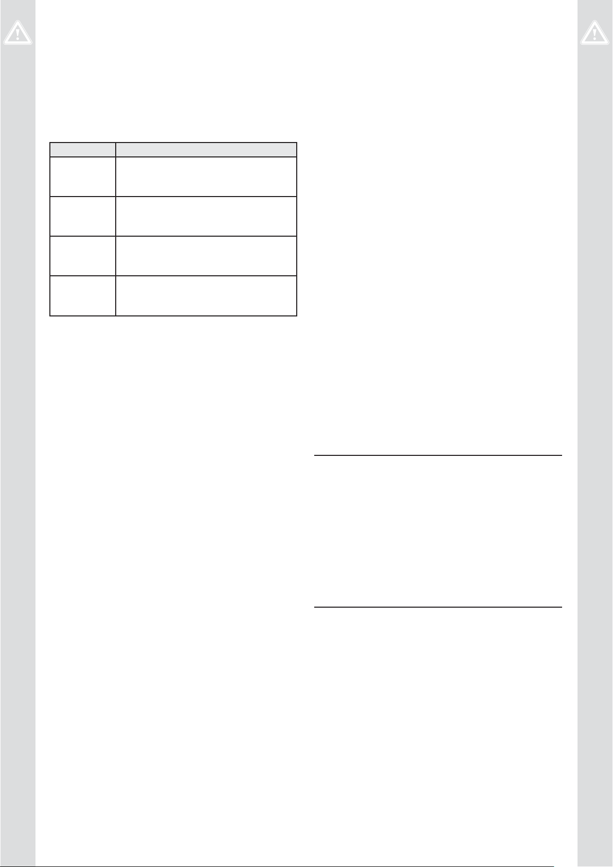
1.1 Symbols used
The warning notes are classifi ed in accordance with the
severity of the possible danger using the following warning
signs and signal words.
Warning symbol Explanation
Danger!
Immediate danger to life or risk of severe
a
e
a
b
1.2 Qualifi cations
Any work carried out must be by suitably qualifi ed personnel.
∙ Incorrect installation can cause damage to the unit, to the
site or injury to others.
personal injury.
Danger!
Risk of death from electric shock.
Warning!
Risk of minor personal injury.
Caution!
Risk of material or environmental damage.
1.3.3 Danger due to improper use
Nonprofessional work on the product can cause damage to
the installation and as a consequence even personal injury.
∙ Only work on the product if you are a competent person.
1.3.4 Risk of material damage by additives in the
heating water
Frost and corrosion protection agents can cause changes
to seals, noise during heating mode and may lead to other
consequential damage.
∙ Do not use any unsuitable frost or corrosion protection
agents.
1.3.5 Risk of material damage caused by
unsuitable tools
The use of unsuitable tools or improper use thereof may cause
damage, such as gas or water leaks.
∙ When tightening or loosening threaded connections,
always use suitable opened spanners, but do not use pipe
wrenches, extensions, etc.
1.3.6 Risk of structural damages by escaping water
Incorrect installation can cause leakages.
∙ Make sure there are no stresses in the hydraulic lines.
1.3 General safety advices
∙ Before to read this chapter, also read the general safety
advices of the operating instructions.
1.3.1 Danger to life by electric shock
Touching live connections can cause serious personal injury.
∙ Before carrying out any work on the product, switch off the
power supply.
∙ Secure the power supply against being switched on again.
1.3.2 Danger to life due to missing or not properly
working safety devices
Missing safety devices can cause life-threatening scalding
and other injuries, for example by burst pipes.
The information contained in this document do not show all
schemes required for a professional installation of safety
devices.
∙ Install the necessary safety devices in the system.
∙ Inform the user about the function and location of safety
devices.
∙ Observe the relevant national and international laws,
standards and guidelines.
∙ Correctly position the seals.
1.4 R410A Refrigerant
Danger!
Risk of injury due to incorrect work on the refrig-
a
R410A fl uorinated greenhouse gases are contained within
a fully sealed system (Kyoto Protocol PES 1975). Under
normal use and conditions, the refrigerant is not dangerous.
Degassing refrigerant fl uid into the atmosphere is prohibited,
except when necessary to ensure personal safety.
The refrigerant fl uid contains gases that, when released into
the atmosphere, may aff ect the environment, contributing
to the greenhouse eff ect and an increase in temperature.
The risk of leakage cannot be excluded for devices intended
to operate for many years and subject to the eff ects of the
environment.
erant circuit!
The appliance contains refrigerant fluid and must
be handled with caution. Any work on the refrigerant circuit must be performed by trained and
approved personnel.
• Only work on the refrigerant circuit if you are a
trained and approved specialist equipped with
appropriate protective equipment.
• Perform draining and filling operations in a
properly ventilated area.
• Avoid any contact with the skin or eyes.
0020154078_00 - 02/13 - Glow-worm
∙ Use only R410A refrigerant.
∙ The tools used for charging, for measuring pressure, for
creating a vacuum and for the recovery of the fl uid must be
compatible with and employed solely for R410A.
3
Page 4

SAFETY
∙ Welding is to be carried out with nitrogen and the circuit’s
air-tightness is to be tested under pressure, with nitrogen.
∙ Refi lling must be done at the liquid phase.
∙ In case of leakage, do not add fl uid: drain the remaining
fl uid from the circuit and eliminate, in accordance with the
applicable regulations.
∙ Create a vacuum in the circuit with a maximum pressure of
10 mbar (10 x 102 Pa) (static pressure).
∙ Bleed the circuit before any welding work.
∙ Comply with the values given in chapter 10 when charging
with refrigerant.
1.5 Intended use
The product is a state-of-the-art product which has been
constructed in accordance with recognised safety regulations.
Nevertheless, there is still a risk of injury or death to the user
or others or of damage to the product and other property in
the event of improper use or use for which it is not intended.
The heat pump is a air -water system which heats all types of
buildings by using the energy contained in the outside air.
The system enhances the recuperated energy so that it can
be utilized by traditional heating (heating fl oor and/or low-
temperature radiators).
The heat pump cannot be used without its control box
Systempro.
Intended use includes the following:
- observing the included operating, installation and
maintenance instructions for this product and any other
parts and components of the system
- installing and fi tting the product in accordance with the
product and system approval
- complying with all of the inspection and maintenance
conditions listed in the instructions.
Any other use than the use described in the instructions at
hand or any use extending the described use is not intended.
Any direct commercial or industrial use is also deemed to be
improper.
Any unintended use is prohibited.
1.6 Rules and regulations
On installing and commissioning the appliance you must
adhere to the technical rules, standards and provisions in
eff ect at the time.
1.7 CE label
The CE mark indicates that the products described in these
instructions are in compliance with the following directives:
- Directive 2006/95/EC of the Council with amendments
"Directive Concerning Electrical Equipment for Use Within
Specifi c Voltage Limits" (Low voltage directive)
- Directive 2004/108/EC of the Council with amendments
"Directive Concerning Electromagnetic Compatibility"
- Directive 97/23/EEC of the Council with amendments
"Directive Concerning pressure equipment"
- Directive 2007/1494/EC of the Council with amendments,
dated December 17, 2007, determining, in accordance with
Directive 2006/842/EC of the Council with amendments,
the label type and the additional requirements as regards
the labelling of products and equipment containing certain
fl uorinated greenhouse eff ect gas.
- Directive 2006/842/EC of the Council with amendments
of May 17, 2006 on certain fl uorinated greenhouse gasses
(OJEU of June 14, 2006)
1.8 Approvals
This product has been fully tested in accordance with:
- BS EN 14511:2011
1.8.1 Local regulations
Benchmark places responsibilities on both
manufacturers and installers. The purpose is to
ensure that customers are provided with the correct
equipment for their needs, that it is installed,
commissioned and serviced in accordance with the
manufacturer’s instructions by a competent person
approved at the time by the Health and Safety
Executive and that it meets the requirements of the
appropriate Building Regulations.
The Benchmark Checklist can be used to demonstrate
compliance with Building Regulations and should be
provided to the customer for future reference.
Installers are required to carry out installation,
commissioning and servicing work in accordance with
the Benchmark Code of Practice which is available
from the Heating and Hotwater Industry Council who
manage and promote the Scheme.
∙ Visit www .centralheating.co.uk for more information.
4
0020154078_00 - 02/13 - Glow-worm
Page 5

1.9 Regulations
1.9.1 Statutory requirements
IMPORTANT
Where no British Standards exists, materials and equipment
should be fi t for their purpose and of suitable quality and
workmanship.
The installation of this appliance must be carried out by a
competent person in accordance the rules in force in the
countries of destination.
Manufacturer’s instructions must not be taken as overriding
statutory requirements.
Standards
On installing and commissioning the appliance you must
adhere to the technical rules, standards and provisions in
eff ect at the time.
Reminder of existing regulatory acts
- EC regulation No. 20372000 from the 29th of June 2000
This European regulation repeals regulation No. 3093/94
and presents the elimination schedules of CFC and HCFC.
It also deals with the collection of refrigerants, system
leaks, particularly systems containing more than 3 kg of
CFC or HCFC, as well as the minimum level of qualifi cation
required by the technicians.
SAFETY
- EC regulation No. 0842/2006 from the 17th of May 2006
regarding the containment, use, collection and disposal
of the fl uorinated greenhouse gases, the labelling and
elimination of the products and equipment containing
these gases, the restriction of use and banning of certain
products from the market, as well as the training and
certifi cation of personnel and companies operating in
the activities targeted by this regulation: refrigeration,
air-conditioning, heat pumps and fi re protection systems
containing greenhouse gases.
1.9.2 Other regulations
Control of Substances Hazardous to Health
Under Section 6 of The Health and Safety at Work Act 1974,
we are required to provide information on substances
hazardous to health. The adhesives and sealants used in this
appliance are cured and give no known hazard in this state.
The refrigerant used in this appliance is R410a the use of
which is strictly controlled by F Gas regulation EN842/2006.
0020154078_00 - 02/13 - Glow-worm
5
Page 6
NOTES ON THE DOCUMENTATION
2 Notes on the documentation
∙ These instructions consist of, Installation, Servicing, Fault
Finding and Replacement of Parts. The instructions are an
integral part of the appliance and must be handed to the
user on completion of the installation.
2.1 Observe other applicable documents
- An anti-freezing protection device runs the heat pump
hydraulic pump when the hydraulic circuit temperature is
lower than 3°C. However, it is necessary to add anti-freeze
to the heat pump hydraulic circuit. Without the addition
of outside energy or in the case of a power cut, the circuit
water can drop below the freezing point.
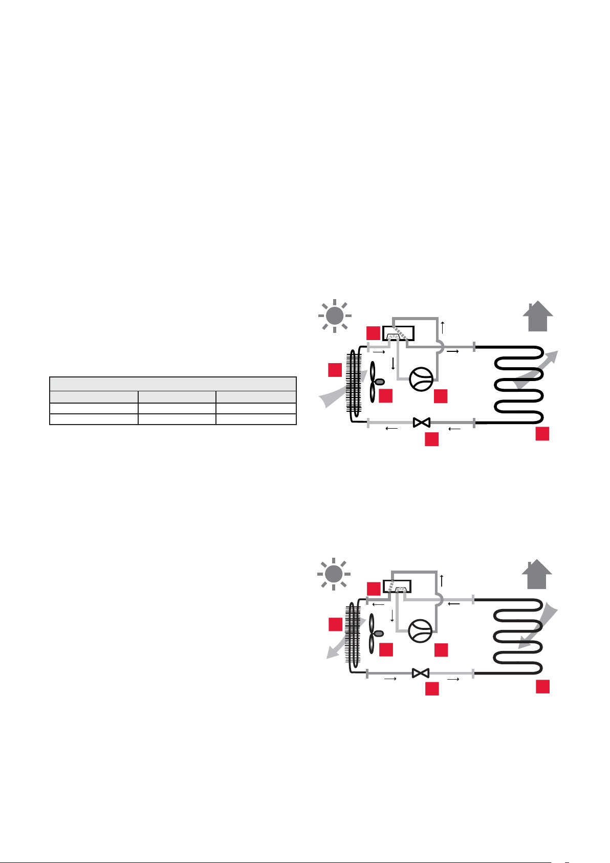
3.2 Concept of operation
A heat pump (HP) is a thermodynamic machine which
transfers heat from one location to another. To do so, it
employs the characteristics of a refrigerant fl uid.
∙ Observe absolutely all operating and installation
instructions enclosed with the product, for the various
parts and components of the system.
2.2 Storing documents
∙ Pass these instructions and all other applicable documents
to the system user.
The system user should retain these instructions so that they
are available when required.
2.3 Validity of the instructions
These instructions apply exclusively to:
Type overview
Product Type designation Article number
Envirosorb3 8 0010011967
Envirosorb3 11 0010011968
For all system schematics and information please refer to the
heatpump system manual.
3 Appliance description
3.1 Safety devices
The system is composed of the following circuits:
- The refrigerant circuit which transfers heat to the
water circuit following the evaporation, compression,
condensation and expansion of the fl uid.
- The heating circuit.
3.2.1 Heating mode
2
1
3
Key
1 Fin exchanger
2 Four way valve
3 Ventilating fan
4 Compressor
5 Expansion valve
6 Plate to plate heat exchanger
4
5
6
- The appliance is designed to operate with an outside
temperature between -20°C and 35°C in heating mode and
between -20°C and 46°C for tank heating.
- A high pressure switch limits the operation of the
appliance when the refrigerant fl uid pressure exceeds
41.5 bar (gauge pressure) (41.5 x 10⁵ Pa) (relative pressure).
- When the appliance is shut down, the compressor
crankcase heater is activated below 7°C at the compressor
outlet to prevent any damage when restarting.
- If the compressor outlet temperature is below 1°C, the
appliance will not allow the compressor to start.
- A temperature sensor at the compressor outlet limits
the operation of the heat pump when the temperature
measured by this sensor is higher than the maximum
limit. This value varies depending on the evaporation and
condensation temperatures.
- The appliance is equipped with a measuring device that
checks the water fl ow rate at start-up.
3.2.2 Defrosting mode
2
1
3
Key
1 Fin exchanger
2 Four way valve
3 Ventilating fan
4 Compressor
4
5
6
6
0020154078_00 - 02/13 - Glow-worm
Page 7
5 Expansion valve
6 Plate to plate heat exchanger
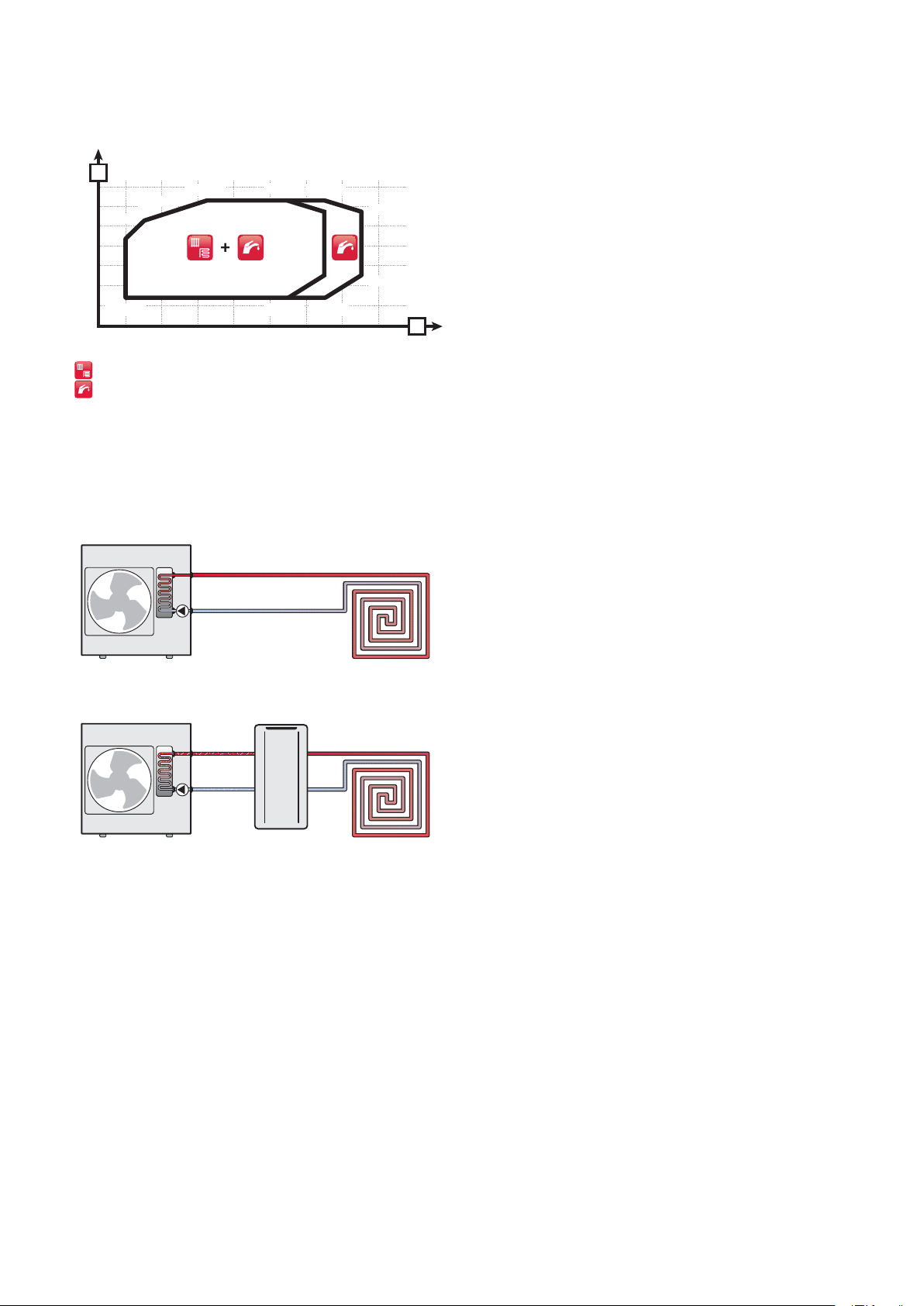
3.2.3 Operating limits in heating mode
APPLIANCE DESCRIPTION
A
70
60
50
40
30
20
10
0
Key
A Water temperature
B Air temperature
[-15;53]
[-20;43]
[-20;15]
-20 -10 0 10 20 30 40 50
Heating operating limits
Domestic hot water operating limits
[2;63]
[28;63]
[35;63]
[35;58]
[35;26]
[46;58]
[46;26]
[35;15][28;15]
B
3.2.4 Permitted hydraulic confi gurations
3.2.4.1 Direct connection to the installation heating
circuit
3.2.4.2 Indirect connection with a hydraulic module
For detailed configurations please refer to the
system manual.
i
0020154078_00 - 02/13 - Glow-worm
7
Page 8

APPLIANCE DESCRIPTION
3.3 Structure of the appliance
3.3.4.1 Hydraulic and refrigerant schematic
3
2
1
4
10
B
5
11
A
17
19
21
Key
1 Ventilating fan
2 Outside air temperature sensor
3 Finned heat exchanger
4 Finned heat exchanger temperature sensor
5 4-way valve
6 Heat pump return circuit temperature sensor
7 Expansion vessel
8 Modulating high performance pump including a water fl ow rate
sensor
9 Water bleed
10 Heat pump fl ow temperature sensor
11 Draining valve for the heat pump circuit
12 Plate to plate heat exchanger
13 Temperature sensor after plate to plate heat exchanger
14 High-pressure circuit maintenance valve
15 Refrigerant pressure switch
14
18
22
24 25
16 Refrigerant circuit high pressure sensor
17 Compressor discharge temperature sensor
18 Rotary compressor
19 Filter
20 Anti-slugging bottle
21 Electronic expansion valve
22 Compressor suction temperature sensor
23 Low-pressure circuit maintenance valve
24 Flow rate limiter in cooling mode
25 Filter
26 Gas buff er
A Heat pump return
B Heat pump fl ow
15
16
20
13
23
26
12
6
7
9
8
8
0020154078_00 - 02/13 - Glow-worm
Page 9

MOUNTING AND INSTALLATION
3.4 Type designation and serial number
Data plate location:
1
1
Key
1 Data plate
The type designation and the serial number are shown on the
data plate.
3.5 Data plate description
The data plate contains the following data:
Abreviation/
symbol
Serial-no Commercial name and serial number
IP The electrical protection class
V/Hz
I max The maximum current
R410A
PS
R The max. working pressure of the cooling circuit
PS
H min
PSH max
COP (Ax/Wxx)
(
Ax/Wxx)
EER (Axx/Wx)
(
Axx/Wx)
Description
The pump + compressor + regulatory devices supply
voltage
The type of refrigerant fl uid, the amount necessary
for fi lling
Minimum and maximum hydraulic pressure
The coeffi cient of performance (COP) for an air
temperature of xx°C and heating fl ow temperature
of xx°C
The heating power for an air temperature of xx°C
and heating fl ow temperature of xx°C
The Energy Effi ciency Ratio (EER) for an air
temperature of xx°C and cooling fl ow temperature
of xx°C
The refrigerating power f
xx°C and cooling fl ow temperature of xx°C
See chapter "CE label"
or an air temperature of
4 Mounting and installation
4.1 Preparing mounting and installation
4.1.1 Delivery, transport and installation on site
4.1.1.1 Transport
Warning!
Risk of injuries due to big carrying loads.
a
b
Too big carrying loads can cause injuries, e.g. on
the backbone.
• Observe all relevant laws and other prescrip-
tions when carrying heavy products.
• Refer to chapter 10 for the weight of the appli-
ance.
• Plan two people at minimum to move
the appliance.
Caution!
Risk of equipment damage due to appliance
transport.
If the appliance is tilted more than 45° during
transport, the refrigerant circuit can be damaged
which may result in complete failure of the installation.
• Do not tilt the appliance more than 45° during
transport.
1
0020154078_00 - 02/13 - Glow-worm
1
Key
1 Transport strap
9
Page 10

MOUNTING AND INSTALLATION
∙ Use the transport strap (1) to move the appliance.
Installation pipework must be designed and installed to
ensure venting of air from the system is possible.
∙ Only lift the appliance from the rear and the side
containing the hydraulic connectors.
∙ Attach the appliance to the two-wheeled trolley with a
strap.
∙ Protect surfaces in contact with the trolley to avoid
scratching or damaging the appliance.
∙ Use a suffi ciently solid ramp to lower the appliance from
the pallet.
4.1.1.2 Unwrapping
B
1
A
13mm
2
4.1.1.3 Checking the equipment delivered
∙ Check the contents of the packages.
The appliance is delivered with a bag of documents and a box
of accessories which contains the following items:
- 1 condensate drain assembly (adaptor + elbow + clip)
- 1 bag of seals
- 4 anti-vibration blocks
- 1 bleeding tube
4.1.2 Observing distances and mounting
clearances
All the drawings dimensions are shown in mm.
i
4.1.2.1 Product dimensions
415
D
3
4
E
Key
1 Bag of documents
2 Accessory box
3 Heat Pump
4 Transport strap
∙ Remove the screws from the transport pallet at the front
and rear of the unit (E).
C
1103
942
162,6
778
162,6
∙ Remove the bag of documents (B) and the accessory box
(A).
∙ Detach the transport strap (C).
∙ Carefully remove the packaging and protections without
damaging the parts of the appliance (D).
10
0020154078_00 - 02/13 - Glow-worm
Page 11

MOUNTING AND INSTALLATION
4.1.2.2 Accessibility
A
E
D
Distance In heating mode only
A > 250 mm
B > 1000 mm
C > 120 mm
D > 600 mm
E > 300 mm
∙ Avoid areas exposed to strong winds directed against the
appliance’s air outlet.
∙ Do not install the fan facing nearby windows. If necessary,
install a noise barrier.
B
C
A
∙ Set the appliance on one of the following supports:
- concrete slabs,
- crane beam,
- concrete blocks.
∙ Do not expose the heat pump to corrosive or dusty
atmospheres (near to dirt roads, for example).
∙ Do not place near to stale air extraction fans.
∙ Provide passages for electrical cables (very low and low
voltage).
4.1.3.1 Properties of the mounting surface
∙ Before choosing the position of the device, carefully read
the warnings relating to safety and the instructions in the
installation and user manuals.
∙ Place the appliance on a beam or concrete blocks or on the
wall supports sold separately.
∙ Ensure that the appliance is protected from water and from
snow.
∙ Comply with the distances above to obtain the correct air
fl ow and facilitate maintenance operations.
∙ Make sure that the available space is suffi cient for the
installation of the water system piping.
∙ If the heat pump is installed in an area subject to heavy
snow fall, ensure that snow does not build up around
the appliance to maintain the distances given above.
Otherwise, install a backup heat generator in the
building’s heating system.
4.1.3 Appliance location
∙ Observe current regulations.
∙ Install the appliance outside.
∙ Do not install the appliance:
- near a heat source,
- near fl ammable materials,
- near the ventilation points of adjacent buildings
- beneath deciduous trees.
∙ Take into account the following when installing the heat
pump:
- prevailing winds,
4.1.3.2 Condensate drain
Danger!
Risk of injury due to freezing of condensates.
a
The condensates fl ow from the central drain located in the
bottom of the heat pump.
Condensates freezing in a passageway can cause
slips.
• Ensure that the drain system presents no risk
of condensates freezing on a passageway.
>100mm
∙ Provide a condensate drain either into a bed of pebbles or
connected to a drain with installation of a siphon.
- the noise generated by the fan and the compressor
- the visual impact on the surrounding neighbourhood.
0020154078_00 - 02/13 - Glow-worm
11
Page 12

MOUNTING AND INSTALLATION
4.2 Mounting the appliance
4.2.1 Opening the appliance
4.2.2 Positioning the appliance
The heat pump must be installed with the anti-
vibration pads supplied. The anti-vibration pads
i
are used to raise the unit, limit the transmission
of vibrations and to facilitate the discharge of
condensates.
4.3 Hydraulic installation
Caution!
Risk of damage caused by contaminated lines!
b
b
B
C
A
4.3.1 Hydraulic connection
A
i
i
∙ Do not weld pipes mounted up : this operation may
damage the seals.
Foreign bodies such as welding remnants, sealing
residue or dirt in the supply lines can cause damage to the product.
• Flush the supply lines thoroughly before instal-
lation.
Caution!
Risk of damage due to corrosion.
If plastic pipes that pass oxygen are used in the
heating installation, this may corrode or sludge
up the appliance’s heating circuit or the appliance
itself.
• If you use plastic pipes that pass oxygen in the
heating installation, add a corrosion inhibitor
to the circuit water.
Insulate the pipes (between the heat pump and
the installation including those underground)
with an UV- and high-temperature-resistant insulation.
In order to avoid the transmission of vibrations to
surrounding structures, flexible hoses of at least
750mm in length should be used for the hydraulic
connections from the heatpump.
∙ Install the appliance level so that the condensates drain
correctly.
∙ If the heat pump is not located at the highest point of the
hydraulic circuit, install additional bleed valves in suitable
places.
∙ Install the following components on the heat pump return
circuit.
Installation with
hydraulic module
- a drain tap
- an air separator (if
necessary)
- an anti-sludge fi lter
- an expansion tank, if the
length of the hydraulic circuit
is greater than the max.
permitted length (see table
below)
- a 3 bar (3 x 10
valve if the hydraulic module
does not have one
Max. length of the hydraulic circuit DN 28
In the case of the installation of a module
without an expansion tank
5
Pa) safety
Installation without
hydraulic module
- a drain tap
- an air separator (if
necessary)
- an anti-sludge fi lter
- an expansion tank suitable
for the complete hydraulic
installation
- a 3 bar (3 x 10⁵ Pa) safety
valve
- a pressure gauge
(recommended)
30 m
12
0020154078_00 - 02/13 - Glow-worm
Page 13

MOUNTING AND INSTALLATION
D
C
5
4
5
3
2
1
Key
1 Return circuit ¼ turn shut-off valve in the direction of the heat
pump (not included) (*)
2 Heat pump fl ow circuit ¼ turn shut-off valve in the direction of
the building (not included) (*)
3 Flow heat pump circuit hose in the direction of the building (not
supplied)
4 O ring
5 Cap
6 Flow heat pump connection (Ø 1¼") to the building
7 Return connection (Ø 1¼") to the heat pump
8 Return circuit hose in the direction of the heat pump (not
supplied)
9 Insulation (not supplied)
(*) Available as an accessory
8
0.75m min.
4
6
7
9
4.3.3 Condensate discharge
Observe these instructions, the legal directives
and the local regulations to evacuate conden-
i
sates.
102,5
1
3
Ø25
550
2
A
B
4
∙ Remove the protection caps (4) located on the connections.
∙ Install the fi lter on the heat pump return pipe. Install it
between 2 shut-off valves in order to be able to remove if
from the circuit and clean it periodically.
∙ Connect a fl exible pipe + the O ring and a shutoff valve to
the heat pump outlet and return connectors.
∙ Check that there are no leaks. Repair if necessary.
4.3.2 Swimming pool option
Caution!
Risk of damage in the case of a direct connection
b
∙ In the case of an installation with a swimming pool option,
take into account the water volume up to the swimming
pool kit for proper sizing of the installation (e.g.:
expansion tanks...).
to the swimming pool.
If the heat pump is connected directly to the
swimming pool, the appliance may be damaged
by corrosion.
• Do not connect the heat pump hydraulic circuit
directly to a swimming pool
• Use a swimming pool kit with an external heat
exchanger.
Key
1 Condensate drain pipe
2 Adapter
3 Clip
4 Elbow
∙ Assemble the elbow and the adapter (A) and then secure it
with the clip (B).
∙ Install the condensate evacuation pipe onto the elbow.
∙ Insert the heat pump electric heater into the pipe to
prevent condensates freezing in the pipe.
∙ Insert the adapter into the hole in the base of the heat
pump (C), then turn the adapter a ¼ turn to lock it into
position (D).
∙ Connect the pipe to the condensate evacuation circuit
either in a bed of pebbles or connected to a drain using a
siphon.
∙ Make sure that the condensate does not stagnate in the
drain hose.
∙ Make sure that the drain hose is not connected tightly to
the waste water piping.
0020154078_00 - 02/13 - Glow-worm
13
Page 14

MOUNTING AND INSTALLATION
4.4 Electrical Installation
Danger!
Risk of electric shock due to an improper electri-
e
Key
1 Electrical wires
2 Insulation
When you connect the electrical wires to a connector on the
electronic board:
∙ Keep a distance of a maximum of 20 mm between
connector and the start of the insulation.
∙ Fix the electrical cables with the clamps installed inside
the heat pump.
4.4.1 Connecting the power input (mains
The external wiring must be earthed, with correct polarity and
in accordance with current standards.
∙ Always check that the Live and Neutral are connected
correctly.
The cables connecting the switchboard and the heat pump
must be:
- Suitable for a fi xed installation.
- weather resistant.
- equipped with wires adapted to appliance’s power rating.
∙ Connect the heat pump to an electrical panel via an
independent protection system (diff erential breaker with at
least 3 mm between each contact).
Additional protection may be required during installation to
ensure surge category II.
The power supply cut-off devices must allow complete
disconnection of the power under the conditions required for
over-voltage category III.
cal connection!
Improper electrical connection can cause electric
shock or might negatively affect the operational
safety of the product and might cause material
damage.
• The electrical connection of the product must
be carried out only by a suitably qualified person.
1
20 mm max.
connection)
2
4.4.1.1 230V heat pump
Caution!
Risk of damage from too great voltage.
b
b
Key
1 Heat pump power supply connection
2 Installation power supply and electric protection
Electricity supply 1/N/PE 230V 50Hz 1/N/PE 230V 50Hz
Circuit breaker 16 A - Type C or D 20 A - Type C or D
Recommended cable size
230V
∙ Connect a cable to the appliance’s power terminal.
∙ Pass the cables through the heat pump cable gland (see
section 4.4.3).
∙ Suitable breaker size and type must be used to fi t
installation site requirements.
∙ Cable size must be suitable for installation site
requirements
At mains voltages higher than 253 V, electronic
components may be destroyed.
• Make sure that the rated voltage of the mains
is 230 V.
Caution!
Risk of malfunction due to the electrical supply.
If the imbalance between the phases of the electrical supply is too large, a malfunction may occur.
• Install the appliance on a electrical supply with
a maximum imbalance of 2% between phases.
X7
FLOOR H
X4
EBUS
X9
21
1
X2
Envirosorb3 8 Envirosorb3 11
3G x 2.5 mm² 3G x 2.5 mm²
4.4.2 24V cable connection
3
2
14
X7
2
FLOOR H
X4
EBUS
1
Key
1 eBUS connection to the heat pump (comply with the polarity ±)
2 Connect the fl oor heating protection device to the heat pump
3 e-BUS connection terminal on the control box
X9
0020154078_00 - 02/13 - Glow-worm
Page 15

Envirosorb3 8 Envirosorb3 11
Recommended cable size
eBus
Recommended cable size
eBUS + FLOOR H
2 x 0.75 mm² 2 x 0.75 mm²
4 x 0.75 mm² 4 x 0.75 mm²
∙ Pass the cables through the heat pump cable gland (see
section 4.4.3).
∙ Connect the e-BUS cable to the system control box
complying with the polarity ±.
∙ If a manual reset floor heating protection device (55°C)
is installed on the heating circuit outlet, remove the link
from the terminal (2) and then connect the floor heating
protection device to this terminal.
4.4.3 Cable routing
Caution!
Risk of appliance malfunction
b
If the very low voltage and low voltage cables are
in the same duct, the very low voltage signal will
be disturbed by the low voltage.
• Run the very low voltage and low voltage
cables in different ducts.
MOUNTING AND INSTALLATION
eBus
230V
ØA
12
C
34
56
7
8910
D
11
12
13
14
15
A
16
ØA
B
Key
eBUS e-BUS cable and fl oor heating protection device cable
gland
230V 230V supply cable gland
∙ Measure the diameter of the cable (A).
∙ Use a drill of the same diameter as the cable and drill
through the cable gland seal (B).
∙ Pass the cable through the cable gland provided for this
purpose (C)
∙ Set the cable gland with 2 fl at spanners (D) to get it tight.
0020154078_00 - 02/13 - Glow-worm
15
Page 16

MOUNTING AND INSTALLATION
4.4.4 Circuit diagram (230V heat pump)
10 9 8 7 6
54321
X23
X30 X60
18 16 15 14 13 12 11 10
9
17
87654321
X21
20 17 16 15 14 13 12 11
10
19
9
18
87654321
X22
HMU
11
43
21
13
X24
X26
X14
12
24V=
S20
24V=
S21
BUS
16
X60DA
14
14567
15
X700
X15
17
FMU
18
X13
19
X16
NL NL NL1X3
X11
NL
X1
230V~
F1
20
X23
10 9 8 7 6
54321
9
10
X21
18 16 15 14 13 12 11 10
9
17
87654321
8
X22
20 17 16 15 14 13 12 11
10
19
9
18
87654321
7
6
2
1
5
4
3
Key
1 Fin exchanger temperature
2 Temperature sensor after plate to plate heat exchanger
3 Refrigerant circuit high pressure sensor
4 Compressor suction temperature sensor
5 Compressor discharge temperature sensor
6 Refrigerant pressure switch
7 Heat pump fl ow temperature sensor
8 Heat pump return temperature sensor
9 Air outside temperature sensor
10 Electronic expansion valve
11 Main PCB
12 Product coding resistor
22
X60
X3
RL1
X6
X1
X8
X5
21
X7
FLOOR H
X4
EBUS
X9
X2
23
UVW
INVERTER
21
43
24
25
13 Diagnostic tool connector
14 Fan
15 Fan management card
16 Compressor crankcase heater
17 Condensate drain electric heater
18 Steady red LED (appliance on)
19 Modulating high performance pump including a water fl ow rate
sensor
20 4 way valve
21 Installer interface
22 Overheating safety
23 Rotary compressor
24 Inverter box
25 Fin exchanger
21
16
0020154078_00 - 02/13 - Glow-worm
Page 17

START-UP
5 Start-up
∙ Refer to the operating instructions before starting the
product.
∙ Check that the diff erential breaker is installed.
∙ Check that the hydraulic and electrical connections are
correct.
∙ Check that the fi lter on the heat pump return is installed.
∙ Check the airtightness of the connections.
∙ Open all the hydraulic circuits’ valves.
5.1 Filling the hydraulic circuit
We recommend that you use propylene enriched
with corrosive inhibitors.
i
∙ Do not dispose of glycol into drains and the environment.
∙ Mix a maximum of 50% of propylene or ethylene glycol
with water. The mixture must provide anti-freezing
protection for the heat pump hydraulic circuit.
∙ Use an antifreeze test kit to ensure accurate dosing.
∙ In order to bleed the hydraulic circuit of the heat pump
during the fi lling, use a fi lling pump.
∙ Put the heat pump circuit under pressure between 1.5 and 2
bars.
The hydraulic circuit pressure may decrease dur-
ing the first month following the commissioning
i
of the installation. It may also vary in accordance
with the outdoor temperature.
5.2 Activating the heat pump
∙ Ensure that the setting of the maximum temperature of
heating fl ow is compatible with the installation.
∙ Refer to the system installation manual in order to fully
activate the installation.
∙ Switch ON the circuit breaker which is located on the
electrical panel and connected to the heat pump.
5.3 Checking the operation of the device
∙ Ensure that the external regulators (thermostat, external
sensor, ...) send a request to the heat pump. In the case of
a multi-zone confi guration, perform the test zone by zone
and ensure that the appropriate zone gets warmer.
14mm
A
1
2
3
4
Key
1 Air trap
2 Flat wrench (*)
3 Hose
4 Deposit (*)
(*) Not included
∙ Connect one end of the hose to the tap (A).
∙ Insert the other end of the hose (3) into the container
during the venting of the circuit.
∙ Ensure that all the heating circuit’s thermostatic valves are
open.
∙ Balance the heat emitters, if necessary.
5.4 Adjustment of HP circuit fl ow
B
5.4.1 Bleeding the hydraulic circuit
If the swimming pool option is installed on the
circuit put the kit's 3 way valve on AUTO position.
i
∙ Connect one end of the hose to the tap.
∙ Insert the other end of the hose into the container in order
to recover any residual glycol during the venting of the
circuit.
∙ Close the shutoff valves at the rear of the heat pump.
∙ Pressurise the hydraulic circuit.
∙ Using a fl at spanner, open the bleed valve.
∙ Open the lower shutoff valve at the rear of the heat pump.
∙ When liquid comes out of the pipe, close the bleed valve
∙ Check that the hydraulic circuit pressure is between 1.5
and 2 bar. Otherwise, top up the hydraulic circuit.
∙ Completely open the two shutoff valves at the rear of the
heat pump.
∙ Remove the hose and the container.
∙ Using a fl at wrench, open the tap a ¼ turn (B) in order to
remove the air present in the glycol circuit, then close it
quickly (in order to avoid emptying the circuit).
0020154078_00 - 02/13 - Glow-worm
17
Page 18

MAINTENANCE
5.4.2 Adjusting the hydraulic circuit fl ow rate
The heat pump is designed to operate above a minimum fl ow
rate. If the heat pump functions at a minimum fl ow rate, this
will result in a loss of power and performance. The heating
comfort will still be guaranteed but the energy savings will be
reduced.
Envirosorb3 8 Envirosorb3 11
Minimum fl ow 380 l/h 540 l/h
Recommended fl ow 1400 l/h 1900 l/h
It is possible to read the fl ow rate directly on the controller.
Depending on the type of fl uid used in the hydraulic circuit,
the fl ow rate displayed on the control box may be over-
estimated.
Example: If you use a 30% propylene glycol mixture and the
fl uid temperature is 5°C, you must subtract 400l/h from the
value displayed on the control box.
∙ Refer to the table below for the various values of over-
estimation of the fl ow rate depending on the fl uid type and
temperature.
Flow rate over-estimation (l/h)
Water 000
Fluid type
Propylene glycol 30% 400 240 120
Propylene glycol 50% 650 500 400
Incorrect venting of the installation may lead to
flow variations.
Fluid temperature
5°C 15°C 25°C
i
∙ If you cannot reach the minimum fl ow rate, install an
auxiliary pump.
∙ Refer to the system documentation for the information
necessary for installing the auxiliary pump.
5.5 Installation of side panel
B
A
C
C
5.6 User information
After completing the installation:
∙ Explain to the user the system operation.
∙ Draw special attention to the safety instructions that the
user must follow.
∙ Inform the user of the necessity to ensure that the system
is regularly maintained (maintenance contract).
∙ Explain to the user how to check the water level/fi lling
pressure of the system.
∙ Answer any questions the user may have.
∙ If you cannot achieve the recommended fl ow rate, adjust
the circuit pressure on the control box and, if necessary,
use the fl ow rate adjusting tap on the hydraulic module.
5.4.2.1 Available pressure in hydraulic circuit of the
heat pump
A
80
70
60
50
40
30
20
10
0
5000 1000 1500 2000
Key
1 Envirosorb3 8 (with the water circuit at 20 ° C)
2 Envirosorb3 11 (with the water circuit at 20 ° C
A Available pressure (kPa)
B circuit fl ow rate (l/h)
2
1
B
6 Maintenance
Danger!
Risk of injury due to unintended intervention on
a
the refrigerant circuit!
The device contains refrigerant fluid and must be
handled with care. Any work carried out on the
refrigerant circuit must be conducted by qualified
engineers.
• Only work on the refrigerant and cooling circuit
if you are a trained and approved specialist
equipped with appropriate protective equipment.
• Perform draining and filling operations in a
properly ventilated area.
• Avoid any contact with the skin or eyes.
18
0020154078_00 - 02/13 - Glow-worm
Page 19

MAINTENANCE
6.1 Observe maintenance intervals
∙ Maintain the product only if you are a competent person.
∙ Carry out annual maintenance.
6.2 Preparing maintenance
6.2.1 Providing spare parts for maintenance and
repair work
∙ In case you need spare parts during maintenance or repair,
exclusively use genuine Glow Worm spare parts.
The genuine component parts of the product have been
certifi ed together with the product in the course of the
CE conformity check. If you do NOT use certifi ed genuine
Glow Worm spare parts during maintenance or repair, the
CE conformity of the product will expire. That is why we
imperatively recommend to install genuine Glow Worm spare
parts.
6.3 Pre-maintenance instructions
Comply with the basic safety rules before performing
maintenance or installing spare parts.
∙ Shut down the system.
6.5 Cleaning
6.5.1 External cleaning
∙ If the appliance needs cleaning, refer to the user manual.
6.5.2 Cleaning the components
∙ Check the absence of ice on the compressor.
∙ Remove any dust from electronic boxes.
∙ Clean the air / refrigerant battery and make sure that air
circulates between the fi ns and around the unit.
∙ Check that condensates can properly drain from the heat
pump by removing the adapter located under the heat
pump (turn it a ¼ turn to unlock).
∙ Clean the evaporator on both sides using a brush with soft
bristles. Remove the fan blades and the rear grill before
cleaning.
Warning!
Risk of minor injury.
a
Handling the fan blades and grill can cause cuts.
• Wear protective gloves to perform this
operation.
∙ Switch off the system electrical supply.
∙ Isolate the hydraulic circuit from the appliance using the
shut-off valves where necessary.
∙ Drain the appliance if you need to replace hydraulic circuit
components.
∙ Protect all electric components from water if you have to
work on the appliance.
6.4 Annual Maintenance
∙ Check the proper functioning of safety devices.
∙ Check the pressure of the water system.
∙ Check tightness of refrigerant circuit.
∙ Check that there are no traces of rust or oil around the
refrigerant circuit’s components.
∙ Ensure that the appliance’s components are neither worn
nor broken.
∙ Check that the wires are fi rmly attached to the electrical
terminals.
∙ Check the appliance’s grounding.
6.6 Draining
∙ Cut off the appliance’s electricity supply.
1
2
14mm
Key
1 Hydraulic circuit venting valve
2 Draining hose
∙ Close the shut-off valves located behind the heat pump.
∙ Engage a hose (2) to the venting valve (1) or place a
container under the venting valve (1) to drain the hydraulic
circuit.
∙ Check the fl ow temperature of the heat pump and the
setting points.
∙ Check that the fan rotates freely.
∙ Check the pressure of the expansion vessel.
0020154078_00 - 02/13 - Glow-worm
∙ Open the bleed valve (1) with a fl at spanner.
Note: if necessary, the heating installation can be drained via
this bleed valve by opening the shutoff valves located at the
rear of the heat pump.
19
Page 20

TROUBLE-SHOOTING
6.7 Checking the appliance status codes
The status codes can be checked at any time to know what
operating phase the appliance is in. These codes can be read
on the system control box screen.
The status codes are described in a table in the appendix (see
section 11.1).
6.8 Checking the electrical installation
∙ Check the electrical installation observing all relevant
regulations
6.8.1 Checking the cables
If the power cable of this product is damaged, then to prevent
danger, only the manufacturer, the after-sales service or
similarly qualifi ed persons shall replace the power cable.
∙ When replacing the power cable see chapter 4.4.
6.9 Start-up after maintenance
∙ Once the maintenance operations have been completed,
start-up the product (see chapter 5).
7.3 Resetting the overheating safety
In the case of overheating, the heat pump shuts down. Once
the temperature has returned to normal, you must reset the
overheating thermostat to restart the heat pump.
1
2
C
∙ After having completed work, check for the tightness of
hydraulic components.
∙ When work on the product is completed, perform an
operational test and check system safety.
7 Trouble-shooting
7.1 Fault diagnosis
The following checks should be performed before proceeding
onto specifi c diagnostics:
∙ Make sure that the electricity supply has not been
interrupted and that the appliance is connected correctly.
∙ Ensure that the isolating valves are open.
∙ Check that all external controls are connected correctly.
7.2 Error codes
The error codes are described in a table in the appendix (see
section 11.2).
∙ Remove the side panels (1 and 2).
(Refer to section 5.5)
Danger!
Danger of death by electrocution
e
Resetting the heat pump can present a risk of
electrocution.
• Do not open the electrical box during the
resetting procedure.
C
In the case of a fault, the fault code number is displayed on
the control unit.
∙ Carry out any necessary repairs.
∙ Switch ON/OFF the appliance using heat pump circuit
breaker.
20
0020154078_00 - 02/13 - Glow-worm
Page 21

DECOMMISSIONING
9 Recycling
9.1 Packaging
∙ Sort the waste to separate those which can be recycled
(cartons, plastics...) from those that cannot (strapping ...).
∙ Recycle the product packaging according to all relevant
regulations.
9.2 Appliance
∙ Do not dispose of your product or any of its accessories in
the household waste.
∙ Make sure the old unit and any accessories are disposed of
properly.
∙ Observe all relevant regulations.
Resetting the heat pump is only possible if the
temperature has dropped below 110°C.
i
∙ Push the screwdriver into the overheating safety(1) until a
“Click” is heard.
8 Decommissioning
∙ Switch off the product.
∙ Isolate the product from the power mains.
∙ Drain the appliance (see chapter 6.5).
∙ Recycle or dispose the product and its components (see
chapter 9).
0020154078_00 - 02/13 - Glow-worm
21
Page 22

TECHNICAL DATA
9.3 Refrigerant fl uid
Attention!
Risk of pollution!
b
The recycling of the refrigerant fl uid must be performed by the
qualifi ed professional who installed the device.
The personnel approved for this recuperation must have an
appropriate certifi cation according to the regulations in force.
This appliance contains R410-A refrigerant fluid
which must never be released to the atmosphere.
R410-A is a fluoride greenhouse gas covered by
the Kyoto protocol.
• Before discarding the appliance, correctly
recover the refrigerant fl uid into an appropriate
container to be recycled in compliance with the
regulations in force.
10 Technical data
This technical data is valid for a new appliance
with its own heat exchangers.
i
Description Unit Envirosorb3 8 Envirosorb3 11-1ph
Min. operating air temperature (heating and tank heating) °C -20 -20
Max. operating air temperature (heating) °C 35 35
Max. operating air temperature (domestic hot water) °C 46 46
Specifi cations, with radiators
(start : 45°C, return : 40°C, dry temperature (wet) 7 (6)°C)
Heating output kW 7,20 10,20
COP* A7(6) W45-40 3,5 3,35
(start : 55°C, return: 47°C, dry temperature (wet) : 7 (6)°C)
Heating output kW 6,60 9,40
COP* A7(6) W55-47 2,70 2.60
Specifi cations, with underfl oor heating
(start : 35°C, return : 30°C, dry temperature (wet) : 7 (6)°C)
Heating output kW 7,60 10,60
COP* A7(6) W35-30 4,50 4,30
(start : 35°C, return : 30°C, dry temperature (wet) 2 (1)°C)
Heating output kW 5,60 8,40
COP* A2(1) W35-30 3,40 3,10
Refrigerant circuit
Type of refrigerant R-410A
Quantity of refrigerant kg 1.950 3.530
Type of compressor Rotary
Type of oil specifi c Polyvinylether (PVE) oil.
Type of regulator Electronic
Maximum relative operating pressure (PS)
Heat pump circuit
Min. fi lling pressure.
bar 41.5 41.5
Pa 41.5 x 10
bar 1 1
Pa 1 x 10
5
5
41.5 x 10
1 x 10
5
5
22
0020154078_00 - 02/13 - Glow-worm
Page 23

TECHNICAL DATA
Description Unit Envirosorb3 8 Envirosorb3 11-1ph
Max. fi lling pressure.
Minimum water fl ow rate l/h 380 540
Maximum water fl ow rate l/h 1400 1900
Expansion vesel capacity l 2 2
Capacity of the hydraulic circuit internal to the heat pump l 4 4
Minimum capacity of the complete hydraulic circuit l 21 35
Plate heat exchanger material AISI 304
Electrical
Supply voltage/frequency V/Hz 1/N/PE 230V 50Hz
Electronic card fuses FMU and HMU T4A / 250V
Inverter controller fuse HRC 20A 550V HRC 32A 550V
Maximum absorbed current (I max) A 16A 20A
Starting current A < 16A < 20A
Index of electrical protection IP25 IP25
Electrical classifi cation II
Surge category II II
Pollution rating 22
Fan electrical consumption W 45 80
Pump electrical consumption W 70 70
Nominal input current at A7W35 A 8,27 12,3
bar 3 3
Pa 3 x 10
5
3 x 10
5
Description Unit Envirosorb3 8 Envirosorb3 11-1ph
Dimensions
Height mm 939 939
Width mm 1103 1103
Depth mm 415 415
Heat pump Ø Water circuit connections " 1 ¼ 1 ¼
Nett total weight kg 105 129
Sound power level : overall exterior noise
(according to EN 12102 and EN ISO 9614-1) under nominal A7W45 conditions.
Fan rotation speed
* Coeffi cient Of Performance (according to EN 14511)
** Energy Effi ciency Ratio (according to EN 14511)
dBA 60 65
tr/
min
-1
550 675
Fluorinated greenhouse gases as identified in the
Kyoto protocol, are contained within a fully
i
sealed system.
0020154078_00 - 02/13 - Glow-worm
23
Page 24

APPENDIX
11 Appendix
11.1 Table of Diagnosis codes
Réf.
Description
état
0 Heat pump waiting
1 Pump pre-run before heating
2 Pump pre-run correct in heating mode
3 Water temperature / heating setting compatibility test
4 Heating phase start activation
5 Pre-run of pump at maximum speed in heating
6 Pre-run of fan in heating
7 Setting the 4-way valve to the heating position
8 Setting electronic expansion valve to the heating position
9 Compressor start request in heating mode
10 Heat pump in heating mode
11 Heat pump in domestic hot water heating mode
12 Water temperature exceeded in heating mode
Water temperature exceeded in domestic hot water heating
13
mode
14 Pump post-run after heating
15 Pump pre-run before de-icing
16 Heat pump in de-icing mode
17 Pump post-run after de-icing
18 Pump remote controlled (top-up)
19 Compressor oil temperature too low for start-up
30 Pump pre-run before cooling
31 Pump pre-run correct in cooling
32 Water temperature / cooling setting compatibility test
33 Cooling phase start activation
34 Pre-run of pump at maximum speed
35 Fan pre-run
36 Setting 4-way valve to cooling position
37 Setting electronic expansion valve to the cooling position
38 Compressor start request in cooling mode
39 Heat pump in cooling mode
40 Water temperature exceeded in cooling mode
41 Post-run of the pump after cooling
50 Pressure balance fault
51 Pressure switch fault
52 Pressure envelop fault detected
53 Start envelop not ok error detected
54 Loss of “cheap tariff ” supply block
55 Refrigerant circuit pressure out of range: HP/LP ratio too low
Réf.
Description
état
Refrigerant circuit pressure out of range: condensation too
56
low
Refrigerant circuit pressure out of range: evaporation too
57
high
Refrigerant circuit pressure out of range: condensation too
58
high
59 Refrigerant circuit pressure too low
60 Compressor outlet over-heat
61 Compressor inlet temperature sensor fault
62 Compressor outlet temperature sensor fault
63 Plate exchanger temperature sensor fault
64 Fin exchanger temperature sensor fault
65 Outside air temperature sensor fault
66 Flow water temperature sensor fault
67 Return water temperature sensor fault
68 Refrigerant circuit high pressure sensor fault
69 Low voltage fault – inverter box bus
70 Inverter box disconnected fault
71 Inverter box over-heat fault
72 Inverter box current-voltage fault
73 Under power fault – inverter box bus
74 Overvoltage power fault – inverter box bus
75 Inverter box internal fault
76 Inverter box radiator sensor fault
77 Inverter box overload fault
78 “FMU” fan circuit board fault
79 e-BUS communications fault
80 Water fl ow rate fault
81 Communications fault with the inverter box
82 Compressor overcurrent fault
83 Water fl ow temperature too high
84 Electronic expansion valve fault
85 Fan speed too low
86 Detection of potential icing in the plate exchanger
87 Water ΔT too high fault
88 Coding resistor fault
89 Heated floor overheating safety device fault
90 4-way valve fault
Appliance fault, refer to section 7.2 to see the corresponding
99
error code.
11.2 Fault codes
∙ Read the heat pump status code number from the control
box screen (see control box installation manual).
∙ Refer to the table in section 11.1 of this manual to see the
heat pump state.
Fault
Description Possible cause
codes
There is an obstacle in the heat
37 Fan speed too low.
Product coding resistor
42
error.
pump’s air fl ow.
The fan motor is defective or
disconnected.
The product coding resistance is
missing or defective.
The resistance value is outside
the authorised limits.
24
Fault
Description Possible cause
codes
The floor heating over
86
heat contact is open.
Spare part
103
identifi cation error.
The heated fl oor temperature is
too high.
The fl ow rate of the installation
hydraulic circuit is too low.
The heated fl oor circuits are
closed.
The circuit board or inverter driver
used as a replacement part does
not correspond to the product.
0020154078_00 - 02/13 - Glow-worm
Page 25

APPENDIX
Fault
Description Possible cause
codes
The compressor inlet
514
temperature sensor or
connection is out.
The compressor outlet
517
temperature sensor or
connection is out.
The heating return
519
temperature sensor or
connection is out.
The fl ow heating
520
temperature sensor or
connection is out.
Coil sensor interrupt or
526
short circuit.
The fl ow on heat pump
water circuit is too low
532
or too high (see section
5.4.2).
The compressor
discharge temperature
536
is too high (depends
on the compressor
operating zone).
Position of 4-way valve
755
error.
The discharge pressure
on compressor is too
high.
537
Blocking fault after 3rd
trigger attempt
The discharge pressure
on compressor is too
high.
537
Blocking fault after 3rd
trigger attempt
The pressure of the
539
low pressure circuit is
too low.
Cooling circuit pressure
546
sensor fault.
The sensor is defective or is not
correctly connected to the main
PCB.
Water pump defective.
There is a lack of water.
Anti-silt fi lter missing or clogged
in the brine water circuit’s
backfl ow.
The circuit was not properly bled.
The pressure drop is too high in
the hydraulic circuit.
The compressor safety thermostat
is tripped.
The pressure switch or its
electrical connection is defective.
The refrigerant fl uid level is low
The sensor is defective or is not
correctly connected to the main
PCB.
Pre-expansion in the liquid line
(load loss)
The electronic expansion valve is
defective.
The plate exchanger is clogged.
There is a mechanical or electrical
problem. Force the 4-way valve
from the control box. While
forcing, check that the coil voltage
is correct.
There is an excess or a lack of
refrigerant.
Vacuum insuffi cient
Presence of incondensables in the
circuit
The pressure switch or its
electrical connection is defective.
Pre-expansion in the liquid line
(load loss)
Poor water fl ow rate.
The water fl ow sensor is defective.
Insuffi cient heat exchange at the
plate to plate exchanger.
Lack of refrigerant.
Lack of airfl ow.
There is no defrosting.
The condensate tray resistance
heater is faulty.
The 4-way valve is defective.
The electronic expansion
valve’s motor is defective or the
connection is defective.
The sensor is defective or not
correctly connected to the main
circuit board.
Fault
Description Possible cause
codes
An excess or a lack of refrigerant.
Presence of incondensables.
The electronic expansion valve is
defective.
554 Operation outside the
compressor's limit.
The expansion valve
582
motor or connection
is out.
The subcooling
temperature sensor
585
in heating mode or
connection is out.
eBus communication
685
with heat pump is out.
Compressor
750
disconnected.
Compressor
751
overcurrent.
752 Inverter driver error.
Communications error
753
with the inverter box.
Fan coil board internal
754
error (FMU).
The air inlet
774
temperature sensor or
connection is out.
Pre-expansion in the liquid line
(load loss)
Insuffi cient heat exchange at the
plate to plate exchanger or tube
exchanger.
The 4-way valve is defective.
The wiring harness is damaged or
disconnected.
The sensor is defective or is not
correctly plugged in to the main
PCB.
The appliance is not connected to
the control box.
The cable polarity is reversed.
The wiring harness is damaged or
disconnected.
Compressor fault.
The heat pump supply voltage is
too low.
The fi nned heat exchanger is
dirty.
The plate heat exchanger is dirty.
The inverter box is damaged.
The inverter box radiator is
blocked.
The supply voltage is incorrect.
The connection between the main
circuit board and the inverter box
is damaged or disconnected.
The inverter box is not powered
up.
The fan is defective.
The connection between the main
circuit board and the fan card is
damaged or disconnected.
The fan card is defective.
The fan card power supply is
defective.
The sensor is defective or not
correctly connected to the main
circuit board.
For further technical information please
call 0844 736 1143
0020154078_00 - 02/13 - Glow-worm
25
Page 26

Page 27

Page 28

GLOW-WORM
0020154078_00 - 02/13 Subject to engineering changes
Nottingham Road,
Belper, Derbyshire.
DE56 1JT
www.glow-worm.co.uk
Because of our constant endeavour for
improvement, details may vary slightly
from those shown in these instructions.
The energy you need
 Loading...