

Page 1

System Installation
STANDALONE
Page 2

Page 3

TABLE OF CONTENTS
INTRODUCTION
1 Instructions guidance ................................................................................................................... 2
1.1 Product documentation .......................................................................................2
1.2 Associated documents ........................................................................................2
1.3 Explanation of symbols .......................................................................................2
1.4 Guarantee registration ........................................................................................2
2 System description ...................................................................................................................... 2
2.1 Concept of operation ...........................................................................................2
2.2 Summary of installation diagrams ........................................................................3
2.3 Diagram 4: Heat pump eBus, one heating zone .....................................................4
2.4 Diagram 7: Heat pump controlled by On/Off contact, one heating zone ...................6
2.5 Example installation with multi-zone heating option .............................................8
2.6 Example of system installation with the domestic hot water cylinder option ..........10
INSTALLATION
3 Confi guring the installation ........................................................................................................ 12
4 "Thermostat / sensor" menu ....................................................................................................... 12
4.1 Thermostat(s) ...................................................................................................12
4.2 Outdoor sensor .................................................................................................13
5 Self check .................................................................................................................................. 13
6 Settings..................................................................................................................................... 14
6.1 Heating ............................................................................................................14
6.2 Domestic hot water ...........................................................................................15
6.3 Cooling ............................................................................................................15
6.4 HP Management ...............................................................................................15
6.5 Resetting parameters ........................................................................................16
7 Commissioning .......................................................................................................................... 16
7.1 Filling and venting the heating circuit .................................................................16
7.2 Venting the HP circuit ........................................................................................18
7.3 Adjustment of HP circuit fl ow .............................................................................18
8 Status reports ............................................................................................................................ 18
9 Re-check and restart ................................................................................................................... 19
10 User information ........................................................................................................................ 19
MAINTENANCE
11 Trouble-shooting ........................................................................................................................ 20
11.1 Fault diagnosis .................................................................................................20
11.2 System fault codes ............................................................................................20
12 Servicing ................................................................................................................................... 21
13 Control unit maintenance menu ................................................................................................... 21
13.1 Test menu .........................................................................................................21
13.2 Aftersales information .......................................................................................22
- 1 -
EN
Page 4

INTRODUCTION
INTRODUCTION
1 Instructions guidance
1.1 Product documentation
The instructions are an integral part of the system appliances and
must be handed to the user on completion of the installation in
order to comply with the current regulation.
• Carefully read the manual, to understand all the information
to enable safe installation, use and servicing. No liability can
be accepted in the event of damage for not complying with the
guidance in this instruction manual.
These instructions consist of, Installation, Servicing, Fault
Finding. The instructions are an integral part of the appliance and
must be handed to the user on completion of the installation.
1.2 Associated documents
- Heat pump use and installation instructions
- Hydraulic module installation instructions
- Systempro Control unit use and installation instructions
- Climapro2 RF programmable Room thermostat use and
installation instructions
- Wireless outdoor sensor installation instructions
- Accessories installation instructions (motorized 2 port valve...)
1.3 Explanation of symbols
a
e
DANGER: Risk of injuries.
DANGER: Risk of electric shock.
2 System description
2.1 Concept of operation
The Standalone system consists of the following components:
-A Glow-worm Envirosorb 5 heat pump,
- A "Standalone" hydraulic module,
- The Systempro control unit
- A Climapro2 RF wireless programmable room thermostat,
- A wireless photovoltaic outdoor sensor
The following options may be added to the system:
- 2 port valves for zoning,
- A domestic hot water cylinder.
2.1.1 Operating principle in heating
The system is designed to provide a heating need of 6kW max at
the reference temperature.
The heat generator consists of a heat pump and a hydraulic
module equipped with an electric heater. The heat emitters can
also be low temperature (heated fl oor, gentle heat radiators...) or
medium temperature (steel panels...). In order to always obtain
the best comfort/economy trade-off , the module heat pump and/
or electric heater supply the heating installation with hot water
at the temperature necessary to obtain the desired ambient
temperature.
When the power of the heat pump is no longer adequate to
ensure heating, the self-controlled electric heater in the hydraulic
module can operate simultaneously in steps of 2 kW up to a
power of 6 kW (in the case of a heat pump ≤ 5 kW the top-up
power is limited to 4 kW when the heat pump is operating). This
guarantees optimal use of the heat pump while guaranteeing
that the total electrical power consumption will never exceed
6kW. When the heat pump is not operating, the electric heater
can reach a power level of 6kW independent of the outside
temperature conditions.
ATTENTION: Risk of damage to the appliance or to its
b
i
surroundings.
IMPORTANT: Important information.
1.4 Guarantee registration
We recommend you complete and return as soon as possible your
guarantee registration card (delivered with the hydraulic module).
If your guarantee registration card is missing you can obtain a
copy or record your registration by telephoning the Glow-worm
Customer Service number 01773 596510.
EN
- 2 -
The changeover point between the heat pump and the electric
heater is managed automatically, depending on the outside and
ambient temperatures. Thus, the system always optimises the
use of the heat pump with respect to the electric top-up heater.
Avoid programmes with high temperature variations
i
in the case of power sizing without a signifi cant
margin (based on a calculation with a stabilised
temperature).
0020096321_01 - 02/11 - Glow-worm
Page 5

INTRODUCTION
2.1.2 Operating principle of the domestic hot water
system
The domestic hot water heating circuit consists of a heat pump,
a 3-way valve and a FLUROCYL hot water tank equipped with an
electric heater.
In order to always obtain the best comfort/economy trade-off ,
the heat pump and/or the FLUROCYL tank electric heater provide
the energy needed to maintain the stored water at the required
temperature.
The lower part of the tank is heated 3 times a day by the heat
pump. In order to provide maximum economy, the electric heater
heats the top part of the tank just to provide the comfort desired
by the user.
The lower the hot water temperature setting, the more the
heat pump will provide energy and, therefore, more economic
operation.
2.2 Summary of installation diagrams
Hybrid Back-up
Heat Pump Diagram
Envirosorb 5 eBus 4
Envirosorb2 7
Envirosorb2 12
Envirosorb2 15
controlled by on/off contact 7
0020096321_01 - 02/11 - Glow-worm
EN
- 3 -
Page 6

INTRODUCTION
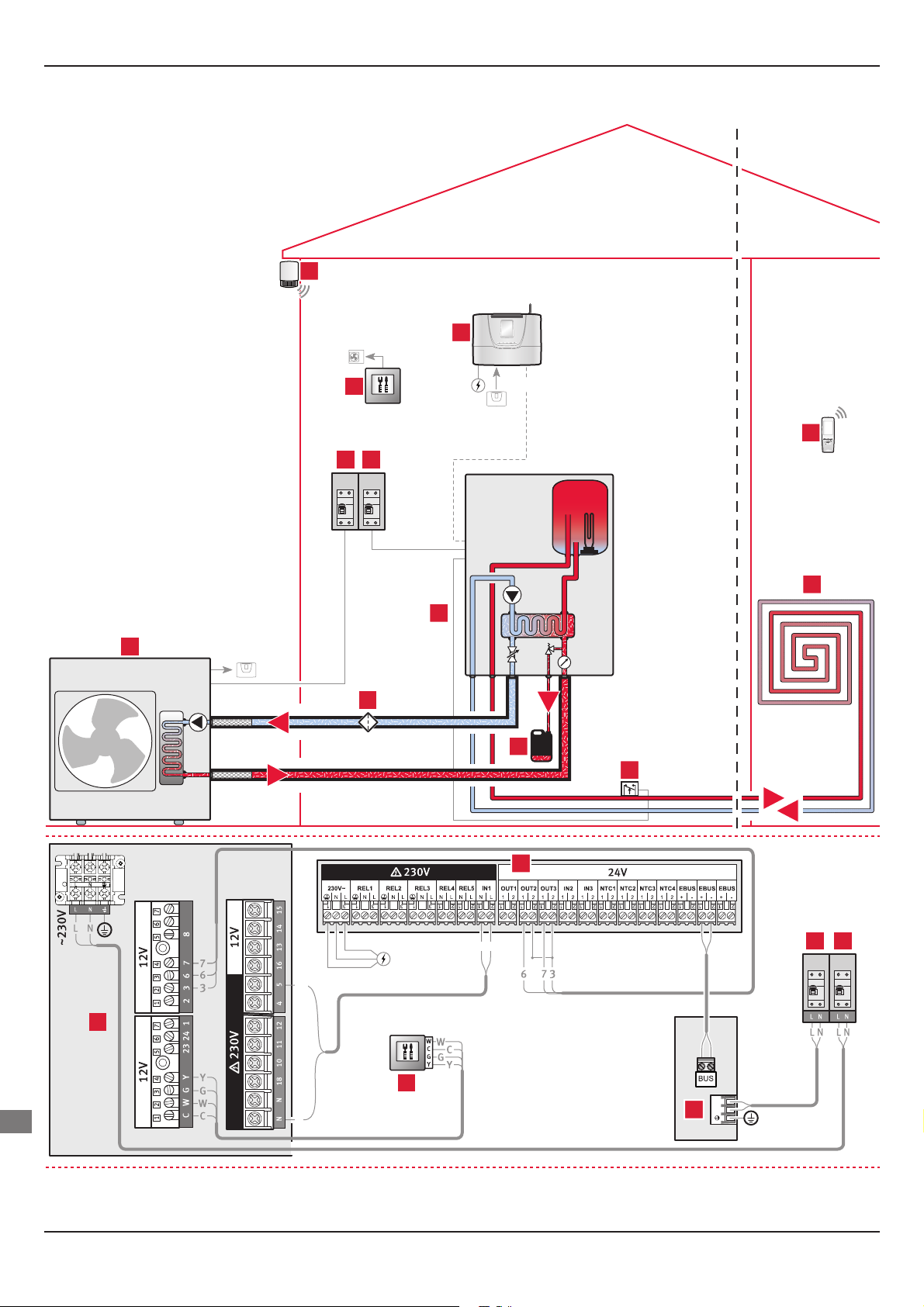
2.3 Diagram 4: Heat pump eBus, one heating zone
5
EBUS
4
6
7 8
230V230V
3
2
9
C
1
B
11
A
5
D
10
E
230V
8
EN
- 4 -
9
2
NL
0020096321_01 - 02/11 - Glow-worm
Page 7
Key
1 Overheating safety (UFH shown, but can be underfl oor or radiators)
2 Hydraulic module
3 Heating circuit
4 Climapro2 RF programmable wireless room thermostat
5 Systempro control unit
6 Wireless outdoor sensor
7 Hydraulic module electrical supply + protection (This must have it's
own single isolation)
8 Heat pump electrical supply + protection (This must have it's own
single isolation)
9 EBus heat pump
10 Heat pump circuit fi lter (not supplied)
11 Glycol PRV discharge
A Heating circuit return
B Heating circuit fl ow
C Heat pump circuit safety valve discharge
D Heat pump circuit fl ow
E Heat pump circuit return
Application conditions
- The Systempro control unit manages the operation of the
boiler, the heat pump and the module.
- The Systempro control unit manages up to 3 heating zones.
INSTALLATION
- Each wireless room thermostat can control a heating zone.
- The installation can be performed with a low-temperature
heated fl oor (heating outlet temperature < 50°C) or low
temperature radiators (heating outlet temperature < 70°C).
- The overheating safety device must be connected to the
hydraulic module pump power supply.
Use 0.75 mm² section cables for the electrical
e
Description of main settings Setting
Diagram no. 4
Did you install a multizone kit ? No
Heating curves 0.1 - 1.5
Max. heating fl ow temperature 30°C < T < 70°C
connections to the control unit.
Control unit settings
0020096321_01 - 02/11 - Glow-worm
EN
- 5 -
Page 8
INSTALLATION
2.4 Diagram 7: Heat pump controlled by On/Off contact, one heating zone
7
8
6
EBUS
9
4 5
230V 230V
10
3
1
2
C
E
12
D
11
B
A
EN
- 6 -
8
L5
N
L5
4 5
230V230V
1
6
NL
N
3
0020096321_01 - 02/11 - Glow-worm
Page 9

Key
1 Heat pump controlled by On/Off contact
2 Heat pump circuit fi lter (not supplied)
3 Hydraulic module
4 Electrical power and protection of the heat pump
5 Electrical power and protection of the module
6 Heat pump control unit
7 Wireless outdoor sensor
8 Systempro control unit
9 Climapro2 RF programmable wireless room thermostat
10 Heating circuit
11 Overheating safety (UFH shown, but can be underfl oor or radiators)
12 Glycol PRV discharge
A Heating circuit return
B Heating circuit fl ow
C Heat pump circuit safety valve discharge
D Heat pump circuit fl ow
E Heat pump circuit return
Application conditions
- The Systempro control unit manages the operation of the
boiler, the heat pump and the module.
- The Systempro control unit manages up to 3 heating zones.
MAINTENANCE
- The heat pump command unit is used as a setting or
diagnostic tool.
- Each wireless room thermostat can control a heating zone.
- The installation can be performed with a low-temperature
heated fl oor (heating outlet temperature < 50°C) or low
temperature radiators (heating outlet temperature < 70°C).
- The overheating safety device must be connected to the
hydraulic module pump power supply.
Use 0.75 mm² section cables for the electrical
e
connections to the control unit.
Control unit settings
Description of main settings Setting
Diagram no. 7
Did you install a multizone kit ? No
Heating curves
Max. heating fl ow temperature 30°C < T < 70°C
Heat pump external shutdown temperature -20°C < T < 20°C
0.1 - 1.5
Heat pump control unit settings
• Refer to the heat pump installation manual to access the
“After-sales” parameters listed below.
Menu Function name Setting
112 Heating curves (*) 7 - 12
114 ECO heating mode (*) 1 - 20°C
(*) Refer to the correspondence table in the “Settings > Heating”
section.
0020096321_01 - 02/11 - Glow-worm
EN
- 7 -
Page 10

INTRODUCTION
2.5 Example installation with multi-zone heating option
2 zone low temperature or high
temperature heating
6
5
4
3 zone low temperature or high
temperature heating
9
8
7
6
5
4
3
3
2
2
1
1
B
A
1010
B
A
EN
- 8 -
LNLN
1
4
7
LNLNLN
1
4
0020096321_01 - 02/11 - Glow-worm
Page 11

Key
1 2 port valve "heating zone 1"
2 Heating circuit zone 1
3 Climapro2 RF programmable wireless room thermostat "zone 1"
4 2 port valve "heating zone 2"
5 Heating circuit zone 2
6 Climapro2 RF programmable wireless room thermostat "zone 2"
7 2 port valve "heating zone 3"
8 Climapro2 RF programmable wireless room thermostat "zone 3"
9 Heating circuit zone 3
10 Systempro control unit
A Heating circuit return
B Heating circuit fl ow
Application conditions
- The Systempro control unit manages up to 3 heating zones.
- Each wireless room thermostat can control a heating zone.
- Zones must be same temperatures.
- The installation can be performed with a low-temperature
underfl oor heating (heating outlet temperature < 50°C) or low
temperature radiators (heating outlet temperature < 70°C).
INTRODUCTION
Use 0.75 mm² section cables for the electrical
e
Description of main settings Setting
Did you install a multizone kit ? Yes
Max. heating fl ow temperature for the low
temperature zone
Max. heating fl ow temperature for the high
temperature zone
- When the 2 port valve is connected to REL3:
• Connect the neutral wire (blue) of the valve to the “N” of the
• Connect the live wire (brown) of the valve to the “L” of the REL3
• Connect the earth wire (yellow/green) of the valve to the earth
• Electrically insulate the red and grey wires of the valve as they
connections to the control unit.
Control unit settings
T < 30°C
T < 70°C
2 port valve electrical connections
REL3 connector.
connector.
of the REL3 connector.
are not used.
- When the 2 port valve is connected to REL4 or 5:
• Connect the neutral wire (blue) of the valve to the “N” and
the live wire (brown) of the valve to the “L” of the REL4 or 5
connector.
• Connect the earth wire (yellow/green) of the valve to the earth
of the REL3 connector.
• Electrically insulate the red and grey wires of the valve as they
are not used.
0020096321_01 - 02/11 - Glow-worm
EN
- 9 -
Page 12

INTRODUCTION
2.6 Example of system installation with the
domestic hot water cylinder option
2
3
1
4
G
230V
16A
3.1
3.2
3.3
F
C
D
A
B
9
E
2
H
5
6
I
8
7
230V
16A
4
EN
- 10 -
3.3 3.1
8
3.2
5
0020096321_01 - 02/11 - Glow-worm
Page 13

Key
1 Hydraulic module
2 Systempro control unit
3 Domestic hot water cylinder
3.1 Top domestic hot water NTC
3.2 Electric heater
3.3 Bottom domestic hot water NTC
4 Electric heater electrical supply + protection (This must have it's
own single isolation)
5 Power relay for the electric heater (not supplied)
6 Heat pump
7 Heat pump circuit fi lter (not supplied)
8 3 port valve
9 Glycol PRV discharge
A Heating circuit return
B Heating circuit fl ow
C Heat pump circuit safety valve discharge
D Heat pump circuit fl ow to module circuit
E Heat pump circuit return
F Cold water supply
G Domestic hot water fl ow
H Heat pump circuit return
I Heat pump circuit fl ow to cylinder circuit
Application conditions
INTRODUCTION
- The Systempro control unit manages the Domestic Hot Water
cylinder.
- The maximum working pressure of the domestic hot water
circuit is 10 bar. If the cold water supply pressure exceeds this,
then a pressure-reducing valve must be fi tted in the supply to
the boiler.
- In areas where the water is ‘hard’ (i.e. more than 200 mg/L
of calcium carbonate), it is recommended that the hot water
setting is reduced and that a scale reducer is fi tted, refer to the
manufacturer’s instructions or consult the local water company
for additional advice.
Use 0.75 mm² section cables for the electrical
e
connections to the control unit.
Control unit settings with eBus heat pump
Description of main settings Setting
Diagram no. 4
Option choice: Domestic Hot Water cylinder On
The type of tank
NTC sensor (1 top NTC)
or
NTC sensor (2 NTC)
Control unit settings with heat pump controlled by On/Off contact
Description of main settings Setting
Diagram no. 7
Option choice: Domestic Hot Water cylinder On
The type of tank NTC sensor (2 NTC)
0020096321_01 - 02/11 - Glow-worm
EN
- 11 -
Page 14

INSTALLATION
INSTALLATION
In the case of a multi-zone installation, fi ll the heating
i
3 Confi guring the installation
• Enter the installer code 96 into the Systempro control unit.
• Refer to the “System description” section for your diagram
1 Choose diagram number.
circuit using the “Filling” mode when commissioning
the control unit. “Filling” mode ensures fi lling by
automatically opening all of the circuit. Refer to the
chapter “Commissioning the Systempro control unit ▸
Commissioning ▸ Filling the heating circuit".
number.
2 Did you installed
a multi-zone kit?
4 The control unit
summarizes your installation.
5 Check the connections you
made to the control unit.
4 "Thermostat / sensor" menu
4.1 Thermostat(s)
1 Select Rmstat/sensor on
the screen.
2 Select Roomstat(s) on the
screen.
2.1 Select number of
heating zones present on the
system.
3 Select DHW cylinder on
the screen, if the option is
installed.
- Z20 kit = 2 heating zones
- Z11 kit = not available
- Z30 kit = 3 heating zones
3.1 Select the corresponding
DHW cylinder.
3 Select the area controlled
by the room thermostat.
4 Via the room thermostat
installer menu, select > RF >
pairing.
EN
0020096321_01 - 02/11 - Glow-worm
- 12 -
Page 15

INSTALLATION
4.2 Outdoor sensor
1 Select Rmstat/sensor on
the screen.
3 Select Connection on the
screen.
2 Select Outdoor sensor on
the screen.
4 Press the button on the
outdoor sensor to connect.
5 Self check
e
The automatic test allows you to check EBUS inputs, NTC inputs,
the RF connection with the room thermostat, the outdoor sensor
radio connection.
i
1 Select Self check on the
Do not modify the cables when connected to the mains.
The other connections are not tested and should be
visually inspected during installation or confi guration
modifi cations.
2 The automatic test will
screen.
start.
The sensor is operational after 24h of exposure to
b
Key
1 Outdoor sensor button
i
light and will therefore not function immediately after
being unpacked.
1
The External T°C Correction allows you to correct the
temperature measured by the outdoor sensor
(+/- 5 ° C, at intervals of 1 ° C - factory setting: 0).
- If the connection is correct, the message "OK" appears
opposite the component.
- If the connection is not correct, the message "Not OK" appears
opposite the component.
In this case, check the connections (wired and wireless) .
ON
0020096321_01 - 02/11 - Glow-worm
EN
- 13 -
Page 16

INSTALLATION
6 Settings
This menu allows you to adjust diff erent functions in accordance
with the connected appliances and to reset all the parameters.
6.1 Heating
The maximum heating output temperature must be
b
1 Select Settings on the
6.1.1 Max. heating fl ow temperature
b
adjusted in accordance with the characteristics of
your installation.
2 Select Heating on the
screen.
Ensure that the heating curve setting is compatible
with the installation.
screen.
1 Select Htg curve settings
on the screen.
2B With the Automatic htg
curve deactivated, you must
choose a heating curve.
2B.2 Choose the heating
curve (see curve and
explanations after).
2A With Automatic htg curve
activated.
2B.1 Select Htg curve setting
on the screen.
3 Select max. heating fl ow T°
on the screen.
4 Adjust the installation's
max. heating fl ow
temperature.
6.1.2 Heating curve
The following menu allows you to select the heating curve (value
adjustable between 0.2 and 4 - factory setting: 0.5), which allows
you to obtain the maximum heating demand for the usual minimum
outdoor temperature for the region in which the sensor is installed.
The automatic heating curve function continually and automatically
seeks the most suitable value to ensure your comfort and
the effi ciency of your heating system. The optimum value is
obtained approximately 24 hours after the system is started. It is
recommended to activate this function.
EN
Ensure that the heating curve setting is compatible
b
Key
1 Older properties with radiators
2 Standard/modern house with radiators
3 Highly insulated modern house with low temperature radiators or
with the installation.
A
underfl oor heating
Heating curve
1 2
B
3
- 14 -
A Heating fl ow temperature (°C)
B External temperature
0020096321_01 - 02/11 - Glow-worm
Page 17

INSTALLATION
Case of a heat pump controlled by On/Off contact
• Refer to the heat pump installation notice to access the “aftersales” parameters listed below.
• Set the heat pump heating curves complying with the
correspondences with the Systempro control unit heating
curves (see table below).
Incorrectly setting these parameters may signifi cantly
b
- Setting of the heat pump parameter 112:
Heating curve of the Systempro
- Example: Setting of the heat pump parameter 112:
Heating curve of the Systempro
impact the system effi ciency.
control unit
0.1 ▸ 02 7
0.3 ▸ 0.4 8
0.5 ▸ 0.7 9
0.8 ▸ 0.9 10
1.0 ▸ 1.2 11
1.3 ▸ Max. 12
control unit
0.1 ▸ 0.2 7
0.3 ▸ 0.4 8
0.5 ▸ 0.7 9
0.8 ▸ 0.9 10
1.0 ▸ 1.2 11
1.3 ▸ Max. 12
Heating curve
of the heat pump
Heating curve
of the heat pump
6.2 Domestic hot water
The lower the temperature of the hot water, the more
i
1 Select Hot water on the
economical the heat pump.
screen.
2 Set max.Domestic Hot
Water temperature.
6.3 Cooling
Function not active for the UK.
6.4 HP Management
This menu is used to set the outside temperature from which the
heat pump must turn off (value adjustable from -20°C to 20°C,
factory setting: 0°C).
To take full advantage of the heat pump, we recommend you to set:
- "-5°C" for 5 kW heat pump because it can not operate below -5°C.
- "-20°C" for the other heat pumps.
In the case where the MODUZONE Z20 or Z30 option is installed:
if the curve setting is "1.2" on the control unit, the curve setting
will be "11" for heat pump parameter 112.
6.1.3 Pre heating
The control unit manages the heating by anticipating the change
in temperature setting between two programmed time ranges.
This function allows it to reach the programmed temperature
more rapidly (factory setting: active). It acts at the fi rst morning
setting change for each zone.
1 Select Pre heating on the
screen.
2 Confi rm your choice.
1 Select HP Management on
the screen.
3 Set the outside
temperature from which the
heat pump must turn off .
2 Select Heat pump stop
temp. on the screen.
0020096321_01 - 02/11 - Glow-worm
EN
- 15 -
Page 18

INSTALLATION
6.5 Resetting parameters
This feature allows you to reset the parameters of the control unit
(factory setting).
The resetting of factory settings is irreversible. Any
b
1 Select Settings reset on
customised confi guration of the control unit will be lost.
the screen.
2 Confi rm your choice.
7 Commissioning
Refer to the hydraulic module instructions for fi lling
i
the heating and glycol water circuits.
7.1 Filling and venting the heating circuit
Filling the heating circuit allows the system to be pressurised.
Venting the heating circuit purges the air present in the heating
circuit.
Suitable external fi lling systems are shown diagrammatically, see
diagram below.
3
2
1
A C
B
5
4
This menu allows you to carry out the necessary operations on
the appliances following installation.
1 Select Commissioning on
the screen.
3
2
1
Key
1 Heating fl ow isolating valve
2 Heating return isolating valve
3 Hydraulic module
4 Temporary fi lling loop (remove immediately after fi lling)
5 Drain point
6 Back fl ow prevention device
7 Tundish
A Heating return circuit
B Heating fl ow circuit
C Domestic cold water supply in
A
B
6
7
C
5
EN
0020096321_01 - 02/11 - Glow-worm
- 16 -
Page 19

INSTALLATION
A - Case of a mono-zone installation :
• Open the diff erent heating circuit air vent (on the pump and
the hydraulic module tank...).
1 Select Air venting on the
screen.
• Open the taps on the module hydraulic jig and the installation
domestic cold water inlet tap.
• Fill the installation until the control unit shows 1.5 bar of
pressure.
• Close the cold water inlet shutoff tap.
• Vent each radiator until normal water fl ow then close the
venting valves.
• Vent the hydraulic module tank.
• Repeat the operation until all the radiators and the module
tank are vented.
2 Select Vent heating circuit
on the screen.
3 The screen displays the
2 Select Begin fi lling
procedure from the screen.
• To stop fi lling press the button .
• Close the fi lling loop.
• Vent each radiator until normal water fl ow then close the
venting valves.
• Vent the hydraulic module tank.
• Repeat the operation until all the radiators and the module
tank are vented.
• Open the diff erent heating circuit air vent (on the pump and
the hydraulic module tank...).
3 Select Air venting on the
screen.
pressure measured in the
system and that installation
fi lling is in progress.
4 Select Vent heating circuit
on the screen.
3 Select Begin manual
venting on the screen.
The venting process is carried
out for 15 minutes. You
can simultaneously run the
venting of the HP circuit.
• Check that the pressure
has not reduced (1.5
bar). If it has, repeat the
previous operations.
When venting is complete, close the diff erent heating
b
The heating circuit can only be fi lled via the control unit if you
have chosen the multi-zone kit option. It is used to open the valves
of each zone.
circuit air vent.
B - Case of a multi-zone installation :
1 Select Fill htg circuit
on the screen
The screen shows the
pressure measured in the
system.
• Open the taps on the
module hydraulic jig and the
installation domestic cold
water inlet tap.
5 Select Begin manual
venting on the screen.
When venting is complete, close the diff erent heating
b
circuit air vent.
The venting process is carried
out for 15 minutes. You
can simultaneously run the
venting of the HP circuit.
• Check that the pressure
has not reduced (1.5
bar). If it has, repeat the
previous operations.
EN
0020096321_01 - 02/11 - Glow-worm
- 17 -
Page 20

INSTALLATION
7.2 Venting the HP circuit
The venting of the HP circuit allows you to purge any air in the HP
circuit.
After fi lling the heat pump circuit with glycol water (following the
instructions of the hydraulic module and heat pump installation
manuals), you can start the heat pump venting function.
1 Select from the screen
▸ Air venting
▸ Vent HP circuit
2 Start the venting
procedure.
7.3 Adjustment of HP circuit fl ow
This function can only be activated for an eBus heat pump. The
fl ow display is not possible with the heat pump on / off .
8 Status reports
This menu enables real-time access to:
- the status of the appliances responding to a request (ON/OFF)
- the information available from the appliances (temperature,
pressure, fl ow, ...),
- register of last 5 faults recorded for each appliance (failure
code and description)
- to reset the report for each appliance.
Information on the heat pump
In the case of an On/Off heat pump, the forcing and information
reading modes are available from the command unit supplied
with the heat pump.
1 Select Status reports on
the screen.
2 Select Heat pump on the
screen.
1 Select Glycol circuit fl ow
on the screen.
3 Start the reading of the
heat pump circuit fl ow rate.
2 Select HP → Module on
the screen.
System information
1 Select Status reports on
the screen.
2 Select System on the
screen.
EN
0020096321_01 - 02/11 - Glow-worm
- 18 -
Page 21

INSTALLATION
Information on heating zone
1 Select Status reports on
the screen.
3 Select the zone you want to
consult.
2 select Heating zones on
the screen.
4 Consult the heating zones
information.
9 Re-check and restart
• Once the system is installed, check the operation of each appliance.
• Start the system to ensure that any adjustments operate correctly
and check that the appliances operate safely.
• Reset the fault reports for all appliances. To do this, refer to
the "Component info." section.
• Check the water-tightness of the appliances and eliminate any
leaks.
• Check the entire control and safety system, settings and operation.
• Start the "Self check" procedure to test the system connections.
10 User information
At the end of the installation, the installer must:
- explain the operation of the appliances and its safety devices
to the user, if necessary provide a demonstration and answer
any questions;
- hand over to the user all the required documentation,
Information about the domestic hot water cylinder option
This menu is only available if you have chosen the domestic hot
water cylinder option.
1 Select Status reports on
the screen.
2 Select DHW cylinder on the
screen.
- advise the user of the precautions necessary to prevent
damage to the system, appliances and the building;
- remind the user to service the appliances annually.
The user shall not interfere with or adjust sealed components.
Any servicing must be carried out by a competent person
approved at the time by the Health and Safety Executive.
0020096321_01 - 02/11 - Glow-worm
EN
- 19 -
Page 22

MAINTENANCE
MAINTENANCE
11 Trouble-shooting
11.1 Fault diagnosis
The following checks should be performed before proceeding
onto specifi c diagnostics:
- Make sure that the electricity supply has not been interrupted
and that the appliance is connected correctly.
- Ensure that the isolating valves are open.
- Check that all external controls are connected correctly.
11.2 System fault codes
The faults described in this chapter should be carried
i
out by a qualifi ed engineer and if needed by the After
Sales Service.
• Refer to the instructions for each element making up the
system for their fault codes.
Fault
Description Cause Solution
codes
Failure in Ebus communication
002
between with the heat pump
Failure in Ebus communication
003
between with the hydraulic module
Heating circuit fl ow temperature sensor
010
failure (open circuit)
Heating circuit fl ow temperature sensor
011
failure (short circuit)
Heating circuit fl ow temperature sensor
012
failure low temperature (open circuit)
Heating circuit fl ow temperature sensor
013
failure low temperature (short circuit)
Domestic water tank temperature
014
sensor failure (open circuit)
Domestic water tank temperature
015
sensor failure (short circuit)
021 Pressure too low <0.5 bar
Failure in communication with the zone
030
1 wireless room thermostat.
Failure in communication with the zone
031
2 wireless room thermostat.
Failure in communication with the zone
032
3 wireless room thermostat.
Failure in communication with the zone
033
4 wireless room thermostat.
Failure in communication with the zone
034
EN
5 wireless room thermostat.
Failure in communication with the zone
035
6 wireless room thermostat.
Failure in communication with the
036
wireless outdoor sensor
The heat pump is not connected to the
control unit.
The heat pump is off .
The hydraulic module is not connected
to the control unit.
The hydraulic module is off .
The sensor is defective or not
properly connected to the control unit
management or hydraulic module.
The sensor is shorted.
The sensor is defective or not properly
connected to the control unit.
The sensor is shorted.
The sensor is defective or not properly
connected to the control unit.
The sensor is shorted.
There is a leak in the heating circuit.
The venting was not carried out
correctly.
The room thermostat is too far from the
control unit.
There is a problem with the batteries in
room thermostat.
The wireless outdoor sensor is too far
from the control unit.
Make sure the heat pump is connected to the control unit.
Ensure that there is no interruption to the electricity network
and that the heat pump is properly connected and turned on.
Make sure that the hydraulic module is connected to the
control unit. Ensure that there is no interruption to the
electricity network and that the hydraulic module is properly
connected and turned on.
Check the sensor’s connections.
Verify that the position and the operation of the sensor are
correct.
Check the sensor’s resistance.
Check the sensor’s connections.
Verify that the position and the operation of the sensor are
correct.
Check the sensor’s resistance.
Check the sensor’s connections.
Verify that the position and the operation of the sensor are
correct.
Check the sensor’s resistance.
Check that there are no leaks.
Drain the heating circuit. Remove air.
Fill the installation.
Check the RF signal quality via the Climapro2 RF installer
menu.
Check the location of the thermostat.
Check that the thermostat’s batteries are installed in their
compartment.
Make sure the battery polarity is not reversed.
Make sure the batteries are not dead.
If so, replace them with new batteries
Check the location of the outdoor sensor. Check that the
sensor’s power supply is correctly provided by a photovoltaic
cell.
- 20 -
0020096321_01 - 02/11 - Glow-worm
Page 23

MAINTENANCE
12 Servicing
• Consult each of the system component’s instructions for more
information about the corresponding maintenance operations.
13 Control unit maintenance menu
• Enter the installer maintenance access code (35) into the
control unit.
13.1 Test menu
This menu allows you to test the operation of all appliances and
the system (HP, zone valves,) present in the installation.
Heat pump test
1 Select System tests on the
screen.
2 Select Heat pump on the
screen.
System test
1 Select System tests on the
screen.
3 Activate the hydraulic
module pump.
2 Select System on the
screen.
4 Activate the Forced module
resistors.
This menu allows you to:
- issue a heating demand to the heat pump (*),
- activate the pump (**)
- activate the fan (**)
- activate the 4-way valve (**)
- activate the crankcase heater (**)
- activate the electrical resistance heater (**)
- activate the heat exchanger’s resistance heater (**)
- activate the defrosting (**)
(*) In the case of a heat pump controlled by an On/Off contact,
switch off the power to the heat pump at the electrical panel for a
few seconds before starting the heating demand.
(**) Only available with an eBus heat pump
Heating zones test
The heating zones can only be tested if you have
i
1 Select System tests on the
3 Activate the multi-zone kit
installed multiple zone valves.
screen.
valve for each zone.
2 Select Zones on the
screen.
0020096321_01 - 02/11 - Glow-worm
EN
- 21 -
Page 24

MAINTENANCE
The domestic hot water cylinder test is only possible
i
if you have selected the domestic hot water cylinder
option.
DHW cylinder test
1 Select System tests on the
screen.
3 Select DHW cylinder
demand on the screen.
2 Select DHW cylinder on the
screen.
4 Select DHW cylinder elec.
resist. on the screen.
13.2 Aftersales information
This menu provides access to Aftersales Service information.
1 Select Parameters on the
screen.
3 Display or modify the
following information:
EN
2 Select After sales info on
the screen.
- date of last access to
installer menus,
- the name of the company
which provides the after
sales service if entered,
- the telephone number
of the company which
provides the after sales
service if entered.
- 22 -
0020096321_01 - 02/11 - Glow-worm
Page 25

Page 26

Page 27

Page 28

GLOW-WORM
0020096321_01 - 02/11 Subject to engineering changes
Nottingham Road,
Belper, Derbyshire.
DE56 1JT
www.glow-worm.co.uk
Because of our constant endeavour for
improvement, details may vary slightly
from those shown in these instructions.
 Loading...