

Page 1
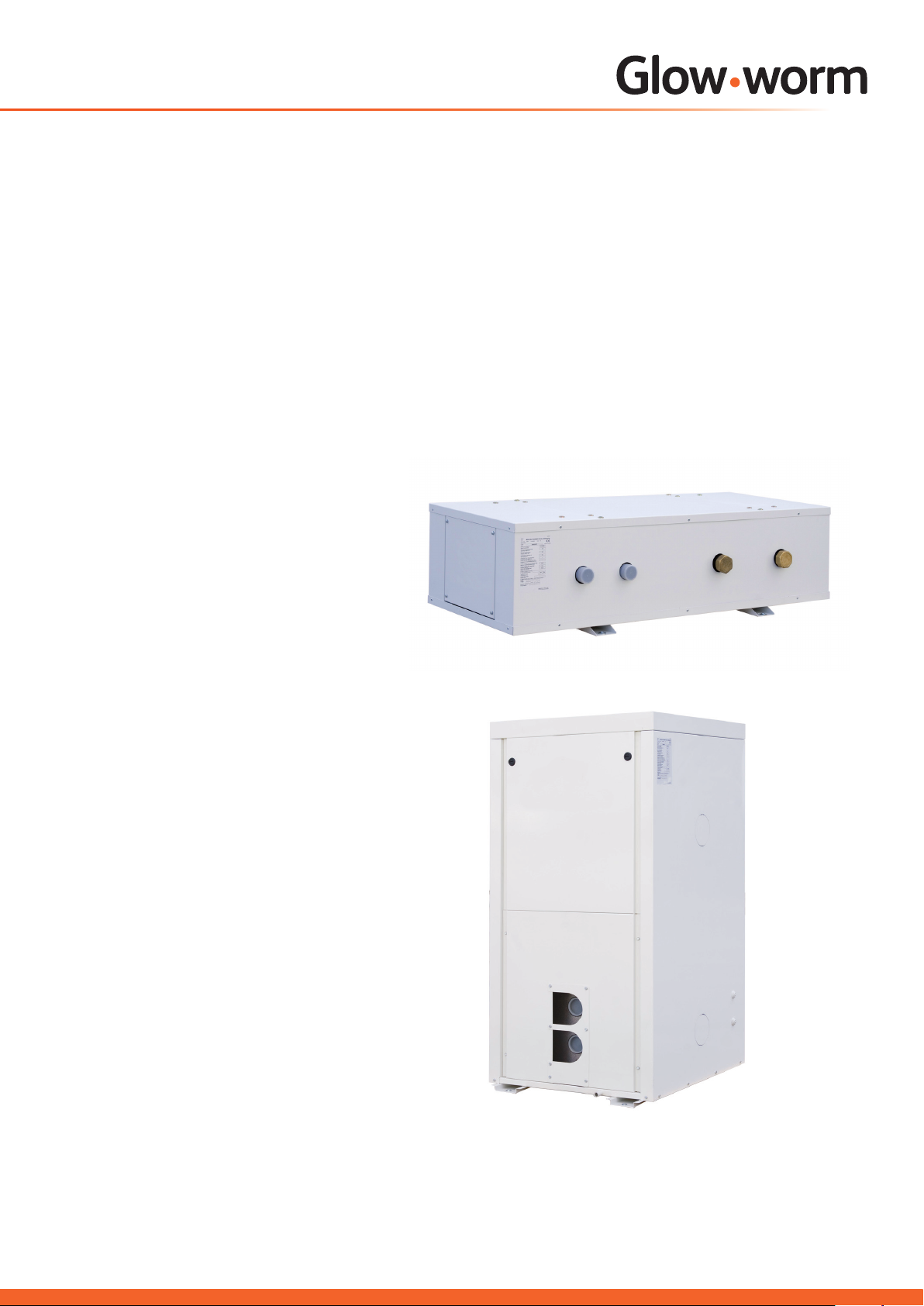
Buffer Vessel
Installation Instructions
60 litre
180 litre
Buffer Vessel
for
heat pump systems
www.glow-worm.co.uk
Page 2

Guarantee Registration
Thank you for installing a new Glow-worm appliance in your home.
Glow-worm appliances are manufactured to the very highest standard so we are pleased to offer
our customers a Comprehensive Guarantee.
This product is guaranteed for 24 months from the date of installation or 30 months from the date
of manufacture, whichever is the shorter, for parts and labour.
The second year of the parts guarantee, from the beginning of the 13th month onwards after
installation or manufacture, is conditional upon the appliance having been serviced by an
approved, qualied installer,
in accordance with the manufacturer’s recommendations. We strongly recommend regular
servicing of your appliance, but where the condition is not met, any chargeable spare parts or
components issued within the applicable guarantee period still benet from a 12 month warranty
from the date of issue by the manufacturer.
We recommend you complete and return as soon as possible your guarantee registration card.
If your guarantee registration card is missing you can obtain a copy or record your registration by
telephoning the Glow-worm Customer Service number 01773 828100.
Customer Service:
01773 828100
Technical Helpline:
01773 828300
General and Sales enquiries:
Tel. 01773 824639
Fax: 01773 820569
To register your Glow-worm product call:
0800 0732142
Benchmark places responsibilities on both manufacturers and installers. The purpose is to ensure that customers are provided
with the correct equipment for their needs, that it is installed, commissioned and serviced in accordance with the manufacturer’s
instructions by competent persons and that it meets the requirements of the appropriate Building Regulations. The Benchmark
Checklist can be used to demonstrate compliance with Building Regulations and should be provided to the customer for future
reference.
Installers are required to carry out installation, commissioning and servicing work in accordance with the Benchmark Code of
Practice which is available from the Heating and Hotwater Industry Council who manage and promote the Scheme.
Visit www.centralheating.co.uk for more information.
2
Page 3

These instructions must be handed to the user on completion of the installation.
CONTENTS DESCRIPTION SECTION PAGE
Warnings 4
INTRODUCTION
Important Information 4
Statutory Requirements 5
INSTALLATION
TECHNICAL
SPECIFICATION
DISPOSAL
Installation 1 6
Technical Data 2 8
Disposal 3 9
3
Page 4

WARNINGS
Metal Parts
This buffer vessel contains metal parts (components) and care should be taken when handling and cleaning,
with particular regard to edges.
Sealed Components
Under no circumstances must the user interfere with or adjust sealed parts.
Important Information
General
Further documents apply in combination with this installation
manual.
We accept no liability for any damage caused by failure to
observe these instructions.
Installation, commissioning and maintenance to the unit must
only be carried out by a competent person.
Control of Substances Hazardous to Health
Under Section 6 of The Health and Safety at Work Act
1974, we are required to provide information on substances
hazardous to health.
The adhesives and sealants used in this appliance are cured
and give no known hazard in this state.
Frost protection
The vessel must be completely drained if it is to be shut down
for a long period of time in an unheated room (winter holidays
etc), unless the heat pump circuit contains the necessary
amount of glycol antifreeze (available as a G-w accessory)
Documents
All installation manuals of the components of the installation
must be observed when installing a closed hot water central
heating system. These installation manuals are included
with the individual parts of the installation and the ancillary
components.
Please pass this installation manual on to the owner of the
system in order for him or her to store it so that it is available
whenever it is required.
Manual Handling
With regards to the “Manual Handling Operations, 1992
Regulations”, the product exceeds the recommended weight
for a one man lift.
4
Page 5

Statutory Requirements
Testing and Certication
This buffer vessel is tested and certicated for safety and
performance. It is, therefore, important that no alteration is
made to the vessel, without permission, in writing, by Glowworm.
Any alteration not approved by Glow-worm, could invalidate
the certication, warranty and may also infringe the current
issue of the statutory requirements.
CE Mark
The CE mark on the buffer vessel indicates that it complies
with the basic requirements of the applicable directives.
IMPORTANT
Where no British Standards exists, materials and equipment
should be t for their purpose and of suitable quality and
workmanship.
The installation of this buffer vessel must be carried out by a
competent person.
Manufacturer’s instructions must not be taken as overriding
statutory requirements.
Statutory Requirements
In GB, the installation of the buffer vessel must comply
with the requirements of the current issue of the following
regulations:
- Electricity at work act.
- Health and safety at work act
- Relevant Utility supplier’s regulations.
- Water regulations and by-laws.
- Environment agency and local council requirements
regarding bore holes, water courses, or noise levels.
- Gas safety installation and use regulations concerning
any associated gas red heat source used within the
heating system.
- Building regulations part “L” and directives concerning
energy saving
- Building regulations such as G3 covering Hygiene and L8
Legieonella.
- COSHH regulations
- Other relevant bodies such as HETAS and OFTEC
5
Page 6

1 Installation
1.1 Description
The buffer vessel is fed with hot water from the heat source
and is used as intermediate storage for hot water that can be
used when required, by the heating circuit, see diagrams 1.1
and 1.2.
The buffer vessel is made of steel and is provided with a with
a mild steel outer casing .
180 Litre
A = to heating installation
B = from heating installation
NOTE: The vessel is intended for use on central heating
systems providing space heating. Provision for domestic hot
water supply via a heat exchanger or cylinder, must not be
connected to the outlet side of the vessel.
15508
Series connection
15509
A = to heating installation
B = from heating installation
Parallel connection
Diagram 1.1
6
Page 7

60 Litre
1 Installation
A = to heating installation
B = from heating installation
Series connection
A = to heating installation
B = from heating installation
15506
Parallel connection
15507
1.2 Site requirements
IMPORTANT: To prevent frost damage to the buffer vessel
and damage caused by escaping water, do not install the
vessel in rooms that are liable to freezing.
Make sure that the oor is level and strong enough to support
the weight of the buffer vessel in its full condition (see Section
2, Technical Data).
Install the buffer vessel as close as possible to the heat pump,
to minimise heat losses. Choose the installation location so
that running and connecting the pipes is practicable. Lag all
the pipes with thermal insulation to prevent energy losses.
1.3 Clearances
When installing, make sure there is adequate clearance to the
walls, so that assembly and maintenance work can be carried
out.
1.4 Unpacking and installing the unit
The Glow-worm buffer vessel is delivered in a packing case
with a separate mini pallet for ease of handling.
The feet of the buffer vessel are secured to the pallet during
transit.
Diagram 1.2
Remove the bolts from the feet of the vessel and discard.
Transport the buffer vessel to its nal installation location.
Position the buffer vessel, always ensuring good access to
the hydraulic connections.
7
Page 8

2 Technical Data
2.1 Identication plate
The identication plate is tted on the side of the outer
casing, please quote reference numbers when ordering spare
parts
2.4 Safety valves
NOTE: These buffers are tted with pressure relief valves as
standard, which are positioned within the casing and will have
to be connected to a suitable drain point where the units are
tted indoors.
2.2 Buffer vessel
The buffers are primarily intended for internal use.
The buffer vessel is available in two sizes
180 and 60l nominal capacity.
2.3 Technical Data
Description Units 60 litre 180 litre
Overall height mm 330 1284
Overall length mm 1190 754
Overall depth mm 500 633
Weight, unlled kg 53 95
Weight, lled kg 110 275
Vessel capacity l 60 180
Permissible operating pressure bar 3.0 3.0
Max. permissible temperature °C 95 95
Connection sizes (series) inches 2 x 1¼M 2 x 2”M
Connection sizes (parallel) Inches 2 x 1½ M 2 x 2½” M
Packaged dimensions mm 1198 x 568 x 486(h) 715 x 765 x 1419(h)
Packaged Weight kg 65 106
8
Page 9

3 Disposal
3.1 Disposal
Both your Glow-worm buffer vessel and its associated
packaging consist mainly of recyclable raw materials.
The buffer vessel, nor any of its accessories, belong in the
household waste. Make sure the old unit and any accessories
are disposed of properly. The transport packaging will be
disposed of by your installer.
9
Page 10

Because of our constant endeavour for improvement, details may vary slightly from those shown in these instructions.
0020084995-02 06.09
Glow-worm, Nottingham Road, Belper, Derbyshire. DE56 1JT
www.high-efciency.info
 Loading...