

Page 1
Supplied By www.heating spares.co Tel. 0161 620 6677
Instructions for Use
Installation and Servicing
T o be left with the user
BBU Fire Front
For use with
56/3e, 56/3pp, 45/2 and56/2
221793A. 06. 00
7441
specially designed
Back Boiler Units only
G.C. No. 37 047 08
BS 6332
BS 5258
This is a Cat I
Reference in these instructions to British Standards and Statutory
Regulations/Requirements apply only to the United Kingdom.
For Ireland the rules in force must be used.
The instructions consist of three parts, User, Installation and Servicing Instructions, which includes the Guarantee Registration
Card. The instructions are an integral part of the appliance and must, to comply with the current issue of the Gas Safety
(Installation and Use) Regulations, be handed to the user on completion of the installation.
Appliance
2H
Guarantee Registration
Thank you for installing a new Glow-worm appliance in your home.
Glow-worm appliances' are manufactured to the very highest standard so we are pleased
In the centre pages are to be found your Guarantee Registration Card, which we recommend you complete and
If this card is missing you can obtain a copy or record your registration by telephoning the Heatcall Customer
Our Guarantee gives you peace of mind plus valuable protection against breakdown by covering the cost of:
to offer our customers' a Comprehensive First Year Guarantee.
return as soon as possible.
Service number 01773 828100.
✔
All replacement parts
❏
✔
All labour charges
❏
All call-out charges
✔
❏
One Contact Local Service
REGISTER YOUR GLOW-WORM APPLIANCE
FOR 1ST YEAR GUARANTEE PROTECTION
CALL 0181 380 2555
Customer Services:
Tel: (01773) 828100
Fax: (01773) 828070
Hepworth Heating Ltd.,
Nottingham Road, Belper, Derbyshire. DE56 1JT
General/Sales enquiries:
Tel: (01773) 824141 Fax: (01773) 820569
Page 2

Supplied By www.heating spares.co Tel. 0161 620 6677
Important Information
CE Mark
The CE mark on this appliance shows compliance with:
1. Directive 90/396/EEC on the approximation of the laws of the Member States relating to appliances burning gaseous fuels.
2. Directive 73/23/EEC on the harmonization of the Laws of the Member States relating to electrical equipment designed for use
within certain voltage limits.
3. Directive 89/336/EEC on the approximation of the Laws of the Member States relating to electromagnetic compatibility - Boiler
and Fire.
INFORMATION FOR THE INSTALLER AND SERVICE ENGINEER.
Under Section 6 of the Health and Safety at Work Act 1974, we are required to provide information on substances hazardous to health.
The Adhesives and sealants used in this appliance are cured and give no known hazard in this state.
FUELBEDS, ARTIFICIAL FUEL
This product uses fuel effect Pieces containing Refractory Ceramic Fibre (RCF), which are man-made vitreous silicate fibres.
Excessive exposure to these materials may cause temporary irritation to eyes, skin and respiratory tract, consequently, it makes
sense to take care when handling these articles to ensure that the release of dust is kept to a minimum.
To ensure that the release of fibres from these RCF articles is kept to a minimum, during installation and servicing we recommend
that you use a HEPA filtered vacuum to remove any dust and soot accumulated in and around the fire before and after working on
the fire. When replacing these articles we recommend that the replaced items are not broken up, but are sealed within heavy duty
polythene bags, clearly labelled as RCF waste. This is not classified as “hazardous waste” and may be disposed of at a tipping site
licensed for the disposal of industrial waste. Protective clothing is not required when handling these articles, but we recommend you
follow the normal hygiene rules of not smoking, eating or drinking in the work area and always wash your hands before eating or
drinking.
INSULATION and SEALS
Ceramic fibre and glass fibre used in insulation panels rope and gaskets.
These can cause irritation to skin, eyes and the respiratory tract.
If you have a history of skin complaint you may be susceptible to irritation. High dust levels are usual only if the material is broken.
Normal handling should not cause discomfort, but follow normal good hygiene and wash your hands before eating, drinking or going
to the lavatory.
If you do suffer irritation to the eyes or severe irritation to the skin seek medical attention.
CONTENTS DESCRIPTION SECTION PAGE No.
Introduction 3
INSTRUCTIONS
FOR USE
INSTALLATION
INSTRUCTIONS
Lighting the Boiler 5
Lighting the Fire Front 9
Cleaning 9
General Data 1 13
Types of Flue Installation 2 15
Fire Front Preperation 3 16
Installation 4 20
Lighting, Testing and Fitting Internal Parts 5 24
Instructions for Use 6 28
SERVICING
INSTRUCTIONS
Servicing and Replacement of Parts 7 28
Fault Finding 8 33
Replacement Parts 9 36
2221793A
Page 3

Supplied By www.heating spares.co Tel. 0161 620 6677
FLAT AREA
FIRE FIXING
FACE
Instructions for Use
890mm
150mm
MAXIMUM
SHELF
DEPTH
840mm
7409
150mm
The Gas Safety (Installation and Use)
Regulations
In your interests and that of safety it is the Law that ALL gas
appliances are installed by a competent person in accordance
with the current issue of the above regulations.
General
These notes should be read and carefully followed for the safe
and economical use of your back boiler and fire front.
Important Notice
If this fire is fitted to a Glow-worm Back Boiler WITHOUT a flue
blockage safety device refer to the Supplementary Installations
in the Instructions for Use.
This appliance is for use only on G20 gas.
The Glow-worm Black Ash 3 BBU gas fire front is to be used
with specially designed Glow-worm 56/3e, 56/3pp, 45/2, 56/2,
45, 56, 45R or 56R Back Boiler Units only.
The fire front and back boiler must be fitted as a complete
appliance.
This is a combined central heating back boiler and gas fire
front. The back boiler and fire front can be operated either
together or independently.
In the event of a power or ignition system failure the fire front can
still be used on its own, instructions on how to do this are given
under “Lighting the Fire Front with a Match or Spill”.
Diagram 1
A slight smell may occur, for a short time, after initial lighting, this
is quite normal and will quickly disappear.
With a little use the interior of the fire front will discolour and
acquire the appearance of a solid fuel fire.
Combustible furniture must not be placed closer than 1metre in
front of the fire front.
Clothing or other flammable materials must not be placed on the
fire front casing.
The convection air openings at the top of the fire front and air
inlet grilles at the sides and base must never be obstructed.
Important: Soft wall coverings, for example, blown vinyl
wallpaper, are easily affected by heat, they may therefore,
scorch or become discoloured when close to a heating appliance.
This should be borne in mind when having a heating appliance
fitted and when redecorating.
The glass panel on this fire front conforms to the requirements
of the current issue of BS1945 and satisfies the Heating
Appliance (Fireguard) Regulations.
The fire front must not be used if this panel is broken or missing.
WARNING. The glass panel gets very hot when the fire front is
on and MUST NOT be touched.
The glass panel does not provide full protection for the young,
elderly or infirm. In such cases extra security must be provided
by fitting a fireguard which complies with the current issue of
BS6539 “Fireguards for use with solid fuel appliances” or the
current issue of BS6778 “Fireguards for use with portable, free
standing or wall mounted heating appliances”.
3
221793A
Page 4

Supplied By www.heating spares.co Tel. 0161 620 6677
Instructions for Use
Maintenance
To ensure the continued efficient and safe operation of the
appliance it is recommended that it is checked and serviced at
regular intervals. The frequency of servicing will depend upon
the particular installation and usage, but in general once a year
should be enough.
If this appliance is installed in rented property there is a duty of
care imposed on the owner of the property by the current issue
of the Gas Safety (Installation and Use) Regulations, Section
35.
It is the Law that servicing is carried out by a competent person.
To obtain service, please call your installer or Heatcall (Glow-
worm’s own service organisation) using the telephone number
given on the fire plinth.
Please be advised that the ‘Benchmark’ logbook should be
completed by the installation engineer on completion of
commissioning and servicing.
All CORGI Registered Installers carry a CORGI ID card, and
have a registration number. Both should be recorded in your
boiler Logbook. You can check your installer is CORGI registered
by calling CORGI direct on :- 01256 372300.
Heat Input - Fire Front
This gas fire front will run for about 4.4hrs at full on rate on one
therm of gas. The price of a therm of gas will vary according to
the tariff in your area.
At tap position 1 - centre section flame effect
At tap position 2 - centre section flame effect with
outer section fuel bed glow
At tap position 3 - centre and outer sections flame
effect with fuel bed glow
At tap position 4 - (full on) full flame effect and fuel
bed glow
Gas Leak or Fault
If a gas leak or fault exists or is suspected the appliance must
be turned off, including the electrical supply and must not be
used until the fault has been put right. Advice/help should be
obtained from your installation/servicing company or the local
gas undertaking.
183mm
Diagram 2
Electrical Supply
WARNING The boiler must be earthed.
Connection of the appliance and any system controls to t h e
mains (230V~50Hz) must be through one unswitched shuttered
socket outlet and a 3A fused 3 pin plug, both to the current issue
of BS1363. Alternatively, a fused 3A fused double pole isolating
switch may be used, having a minimum double pole contact
separation of 3mm, serving only the appliance and system
controls.
The colours of three core flexible cable are, blue - neutral, brown
- live, green and yellow - earth.
As the markings on your plug may not correspond with these
colours, continue as follows:The wire coloured blue must be connected to the terminal mark
“N” or black.
The wire coloured brown must be connected to the terminal
marked “L” or red.
The wire coloured green and yellow must be connected to the
terminal marked “E”, green or the earth symbol
.
7410
Clearances
A shelf or surround of a maximum depth of 150mm may be
fitted, provided clearances are as diagram 1, however, for every
extra 25mm above the fire front the depth of the shelf may be
increased by 25mm.
On no account may carpet or other combustible material be laid
directly under the fire front, unless the minimum clearances
shown in diagram 2 is achieved.
The dimension is taken from the bottom of the fire front casting
to the top of the carpet pile or other floor covering.
Frost
CAUTION. If the back boiler is to be out of use for any long
period of time during severe weather conditions we recommend
that the whole of the system, including the back boiler be
drained off to avoid the risk of freezing up.
If an immersion heater is fitted in the domestic hot water cylinder
make sure that it is switched off.
If in doubt your installation/servicing company or the local gas
undertaking should be contacted
4221793A
PLINTH
7444
Diagram 3
Page 5

Supplied By www.heating spares.co Tel. 0161 620 6677
Instructions for Use
Lighting the Boiler (BBU 56/3e ONLY)
This appliance is fitted with a flue blockage safety device which
will shut down the appliance in the event of abnormal flue
conditions. This device is NOT a substitute for an independently
mounted Carbon Monoxide detector.
If the boiler shuts down frequently for no apparent reason the
first things to be checked are the chimney and air inlets into the
room. Any problems found must be put right, by a competent
person, before the boiler is used again.
If the burner does go out, wait three minutes before relighting.
For any other reason, wait two minutes before relighting the
burner.
The boiler controls are situated behind the fire front plinth, see
diagram 3.
To remove the plinth grasp each side and pull it gently forwards
until it disengages.
Refer to diagram 4 to identify the controls.
Turn off the electrical supply at the mains supply outside the
unit.
See that all other controls are set for heating. The clock, room
thermostat and programmer, if fitted, will be situated away from
the unit. See manufacturers’ instructions supplied with these
items.
Turn the control thermostat knob “A” to the Off position "O", that
is, fully anti-clockwise (“O” to be against the pointer “B”).
Switch on the electrical supply to the back boiler unit. After a 30
second delay the pilot will automatically light.
This is indicated by the green light illuminating on the lockout
reset button “C”.
Note: Should the red light on the lockout reset button “C” come
on, it indicates that the pilot light is not operating correctly, or the
flue blockage safety device has been activated.
When the fault has been corrected the lockout reset button “C”
must be depressed.
NO ATTEMPT SHOULD BE MADE TO RELIGHT THE BOILER
UNTIL ANY FAULT HAS BEEN CORRECTED. EXPERT
ADVICE SHOULD BE SOUGHT.
Adjust the control thermostat knob “A” to the required setting
between "MIN" and “MAX”.
“MAX” is approximately 82°C.
The temperature of the hot water cylinder should be periodically
raised to 60°C.
Check that all external controls are also set to your requirements.
If the burner goes out for no apparent reason it is IMPORTANT
that the advice given under “Safety Device” is followed.
To Turn the Boiler Off
For short periods, turn control thermostat knob “A”
anti-clockwise until Off position "O" is opposite setting point.
The pilot will remain alight if there is a call for heat. To relight the
main burner turn control thermostat knob “A” clockwise to the
desired setting between "MIN" and “MAX”.
For longer periods, turn control thermostat knob “A” anticlockwise to Off position "O". Switch off the electrical supply to
the appliance.
To relight follow the full lighting instructions given above.
CONTROL BOX
GAS CONTROL VALVE
POINTER
“B”
MAX
0
MIN
GREEN
RED
CONTROL
THERMOSTAT
KNOB “A”
OVERHEAT CUTOFF DEVICE
(sealed systems only)
LOCKOUT
RESET
BUTTON “C”
BBU 56/3e ONLY
5
6821
Diagram 4
221793A
Page 6

Supplied By www.heating spares.co Tel. 0161 620 6677
Instructions for Use
Lighting the Boiler (BBU 56/3pp ONLY)
This appliance is fitted with a flue blockage safety device which
will shut down the appliance in the event of abnormal flue
conditions. This device is NOT a substitute for an independently
mounted Carbon Monoxide detector.
If the boiler shuts down frequently for no apparent reason the
first things to be checked are the chimney and air inlets into the
room. Any problems found must be put right, by a competent
person, before the boiler is used again.
If the burner does go out, wait three minutes before relighting.
For any other reason, wait two minutes before relighting the
burner.
The boiler controls are placed behind the fire front plinth, see
diagram 3.
To remove the plinth, pull it gently forwards until it is free.
Refer to diagram 4a to identify the controls.
Turn off the electrical supply at the mains supply outside the
appliance.
See that all other controls are set for heating. The clock, room
thermostat and programmer, if fitted, will be situated away from
the unit. See manufacturers’ instructions supplied with these
items.
Turn the control thermostat knob “D” to the Off position "O", that
is, fully anti-clockwise (“O” to be against the pointer “E”).
Push in and slightly turn gas control knob “F” clockwise until
” is against its setting point, that is, set to “Off”.
“
Push in slightly and turn gas control knob “F” anticlockwise until
“
” is against its setting point “G”, then push fully in and hold
in. At the same time press and release piezo button “H” until
pilot burner lights.
At initial lighting of the boiler air may be present and several
attempts may be needed to light the pilot. Keep the gas control
knob “F” pushed in whilst operating the ignition button.
When the pilot is alight and stable, keep knob “F” fully pushed
in for about 15 seconds then release. Check that the pilot is still
alight.
If the pilot burner fails to stay alight turn gas control knob “F” to
”, that is, fully clockwise. Wait three minutes. Repeat the
“
lighting operation, only now keep the gas control knob “F”
pushed in for a little longer than before after the pilot has lit.
NOTE. If the burner does go out, wait three minutes before
relighting. For any other reason, wait two minutes before
relighting the burner.
Push gas control knob “F” in slightly and turn anticlockwise until
” is against the setting point “G”.
“
Note. If gas control knob “F” is turned to until “
setting point “G”, a safety lock prevents it being turned on again.
No attempt should be made to turn the valve on again until at
least three minutes have elapsed.
Turn on the electrical supply to the unit.
Turn thermostat control knob “D” clockwise until “MAX” is
against the setting point, the main burner will light.
Adjust the thermostat to the required setting between “MIN” and
“MAX”. “MAX” is about 82
Check that all external controls are set to your requirements.
Refit the plinth by carefully locating the top edge of the plinth into
the sliders, then push gently back as far as it will go.
o
C.
” is against the
To Turn the Boiler Off
For short periods, turn thermostat control knob “D” anticlockwise
until “O” is against setting point "E". The pilot will stay alight, to
relight the main burner, turn thermostat control knob “D” clockwise
to the desired setting between “MIN” and “MAX”.
For longer periods, push in slightly gas control knob “F” fully
clockwise until '
thermostat control knob “D” anticlockwise to “O”.
Switch off the electrical supply the appliance. To relight follow
full lighting operation.
' is against the setting point “G”. Turn
CONTROL BOX
POINTER
“E”
CONTROL
THERMOSTAT
KNOB “D”
BBU 56/3pp ONLY
PIEZO UNIT
BUTTON “H”
GAS
CONTROL
KNOB “F”
SETTING
6822
POINT
“G”
Diagram 4a
6221793A
Page 7

Supplied By www.heating spares.co Tel. 0161 620 6677
Instructions for Use
Lighting the Boiler (45/2 and 56/2 ONLY)
This appliance is fitted with a flue blockage safety device which
will shut down the appliance in the event of abnormal flue
conditions. This device is NOT a substitute for an independently
mounted Carbon Monoxide detector. If the boiler shuts down
frequently for no apparent reason the first things to be checked
are the chimney and air inlets into the room.
An additional cause of the flue blockage safety device shutting
the fire down could be that the filter in the pilot port of the gas tap
has become blocked.
Any problems found must be put right, by a competent person,
before the boiler is used again.
The boiler controls are placed behind the fire front plinth.
To remove the plinth, pull it gently forwards until it is free, see
diagram 3.
Refer to diagram 4b to identify the controls.
Turn off the electrical supply at the mains supply outside the
unit.
Check that all controls are calling for heat.
The clock, room thermostat and programmer, if fitted, will be
remote from the appliance, refer to manufacturer’s instructions
supplied with them.
Turn the thermostat control knob “B” to Off position "O", that is,
fully anticlockwise, “O” to be against the pointer.
Push in and slightly turn gas control knob “A” clockwise until'
against its setting point, that is, set to “Off”.
Push in slightly and turn gas control knob “A” anticlockwise until
' is against its setting point, then push fully in and hold in. At
'
the same time press and release piezo button “D” until pilot
burner “E” lights. Look at flame through viewing window “F”.
At initial lighting of the boiler air may be present and several
attempts may be needed to light the pilot. Keep the control
knob “A” pushed in whilst operating the ignition button.
When the pilot is alight and stable, keep knob “A” fully pushed
in for about 15 seconds then release. Check that the pilot is still
alight, look through window “F”.
'is
If the pilot burner fails to stay alight turn gas control knob “A”
“Off”, that is, fully clockwise. Wait three minutes. Repeat the
lighting operation, only now keep the control knob “A” pushed
in for a little longer than before after the pilot has lit.
NOTE: If the burner does go out, wait three minutes before
relighting. For any other reason, wait two minutes before
relighting the burner.
Push control knob “A” in slightly and turn anticlockwise until
' is against the setting point.
'
Note. If gas control knob “A” is turned until '
setting point, a safety lock prevents it being turned on again. No
attempt should be made to turn the valve on again until at least
three minutes have elapsed.
Turn on the electrical supply to the unit.
Turn the boiler thermostat knob “B” clockwise until “MAX” is
against the setting point, the main burner will light.
Adjust the thermostat to the required setting between “MIN”
and “MAX”. “MAX” is about 82
Check that all external controls are set to your requirements.
Refit the plinth by carefully locating the top edge of the plinth
into the sliders, then push gently back as far as it will go.
o
C (180oF).
' is against the
To Turn the Boiler Off
For short periods, turn thermostat control knob “B” anticlockwise
until “O” is against setting point. The pilot will stay alight, to
relight the main burner, turn thermostat control knob “B”
clockwise to the desired setting between “MIN” and “MAX”.
For longer periods, push in slightly gas control knob “A” fully
clockwise until '
control knob “B” anticlockwise to “O”. Switch off the electrical
supply the appliance. To relight follow full lighting operation.
' is against the setting point. Turn thermostat
'D' PIEZO
UNIT BUTTON
SETTING
POINT
BBUs 45/2 and 56/2 ONLY
'E' PILOT BURNER
'B'
THERMOSTAT
CONTROL KNOB
'F' VIEWING
WINDOW
'A'
GAS VALVE
CONTROL KNOB
7
7997
SETTING
POINT
OFF
PILOT/IGNITION
MAIN BURNER
Diagram 4b
221793A
Page 8

Supplied By www.heating spares.co Tel. 0161 620 6677
Instructions for Use
Supplementary Instructions
NOTE: These supplementary instructions are only
applicable where the back boiler unit does not have a flue
blockage safety device and should otherwise be ignored.
As this fire front may be fitted to a Glow-worm 45, 56, 45R
or 56R back boiler unit WITHOUT a flue blockage safety
device, the following instructions on how to light the boiler
should be read and followed in place of those in the main
instructions for use.
To check if a flue blockage safety device is fitted, refer to the
inset in diagram 5, if one is fitted, this supplement MUST be
ignored.
Lighting the Boiler
The boiler controls are placed behind the fire front plinth.
To remove the plinth, pull it gently forwards until it is free.
Refer to diagram 5 to identify the controls.
Turn off the electrical supply at the mains supply outside the
appliance.
Check that all controls are calling for heat.
The clock, room thermostat and programmer, if fitted, will be
away from the unit, see manufacturer’s instructions supplied
with them.
Turn the thermostat control knob “B” to OFF Position "O", that
is, fully anticlockwise, “O” to be against the pointer.
Push in and slightly turn gas control knob “A” clockwise until'
against its setting point, that is, set to “Off”.
Push in slightly and turn gas control knob “A” anticlockwise until
'
' is against its setting point, then push fully in and hold in. At
the same time press and release piezo button “D” until pilot
burner “E” lights. Look at flame through viewing window “F”.
'is
At initial lighting of the boiler air may be present and several
attempts may be needed to light the pilot. Keep the control knob
“A” pushed in whilst operating the ignition button.
When the pilot is alight and stable, keep knob “A” fully pushed
in for about 15 seconds then release. Check that the pilot is still
alight, look through window “F”.
If the pilot burner fails to stay alight turn gas control knob “A”
“Off”, that is, fully clockwise. Wait three minutes. Repeat the
lighting operation, only now keep the control knob “A” pushed
in for a little longer than before after the pilot has lit.
NOTE: If the burner does go out, wait three minutes before
relighting. For any other reason, wait two minutes before
relighting the burner.
Push control knob “A” in slightly and turn anticlockwise until '
is against the setting point.
Note. If gas control knob “A” is turned until '
setting point, a safety lock prevents it being turned on again. No
attempt should be made to turn the valve on again until at least
three minutes have elapsed.
Turn on the electrical supply to the unit.
Turn the boiler thermostat knob “B” clockwise until “MAX” is
against the setting point, the main burner will light.
Adjust the thermostat to the required setting between “MIN” and
“MAX”. “MAX” is about 82
Check that all external controls are set to your requirements.
Refit the plinth by carefully locating the top edge of the plinth into
the sliders, then push gently back as far as it will go.
o
C (180oF).
' is against the
'
INSET: Showing a Flue Blockage
Safety Device fitted.
'E' PILOT BURNER
SETTING
POINT
'B'
THERMOSTAT
CONTROL
KNOB
'D' PIEZO
UNIT
BUTTON
45, 56, 45R or 56R Back Boiler Unit
WITHOUT a flue blockage safety device
'F' VIEWING
WINDOW
'A'
GAS VALVE
CONTROL
KNOB
5342
SETTING
POINT
OFF
PILOT/IGNITION
MAIN BURNER
Diagram 5
8221793A
Page 9
Supplied By www.heating spares.co Tel. 0161 620 6677
Instructions for Use
Lighting the Fire Front
CAUTION. If the glass panel or internal fire parts are damaged
do not light or use the fire front before replacement parts are
fitted.
The fire front is fitted with a flue blockage safety device which
will shut it down if there is a problem with the chimney. If the fire
front shuts down frequently, for no apparent reason the first
thing to be checked are the chimney and the air inlets into the
room. An additional cause could be that the filter, in the gas tap
has become blocked.
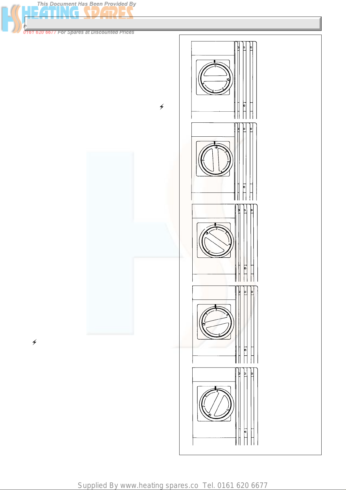
Push the control knob fully in and turn it anticlockwise to “1
ignition, clicking of the ignition will be heard and the burner will
light.
IMPORTANT. If the burner does not light within three seconds,
release the tap knob, wait ten seconds and repeat the lighting
operation.
Keep the knob pushed in for ten seconds, during which time the
ignition system will continue to operate, indicated by the clicking.
Air may be present in the supply to the fire front so that the initial
lighting operation may need to be repeated.
To change settings: Push in and turn. Refer to diagram 6.
If the burner goes out for any reason whilst the fire is turned on,
turn off.
Wait three minutes before relighting as above.
If relighting for any other reason wait two minutes before doing
so.
It can take several minutes for the fuel effect pieces to glow and
the flame effect to appear.
To turn off, turn the tap fully clockwise to “O” position and
release.
If there is a visible build up of soot on the fuel effect pieces follow
the instructions in Section on “Cleaning the Fire”.
7581
APPLIANCE OFF
“
IGNITION POSITION
AND CENTRE
SECTION
FLAME EFFECT
CENTRE SECTION
FLAME EFFECT
WITH OUTER
SECTIONS
FUELBED GLOW
Lighting the Fire Front with a Match or Spill
This is a temporary measure, to be used only in the event of the
failure of the battery or the spark generator.
Make sure that the fire front is cold before starting.
Remove the front casting, see diagram 5.6. Take care as it is
made of cast iron.
Hold a lighted spill or long match and position it so that the flame
is over the burner, see diagram 7.
Keep the spill in position, push in and turn the gas tap to position
“1.
“ ignition and the burner will light. Keep the knob pushed
for about ten seconds and the burner will stay alight.
If the burner should go out, wait for 3 minutes, then repeat the
above, but now keep the knob pushed in for a little longer.
Once lit operate the gas tap normally.
This is a temporary measure only and the battery should be
replaced or the ignition system repaired as soon as possible.
Cleaning your Fire
WARNING. This appliance contains metal parts (components)
and care should be taken when handling and cleaning, with
particular regard to edges.
Any cleaning work must only be carried out when the fire front
is cold.
Under normal circumstances dusting should be enough. An
occasional wipe over with a damp cloth will help remove marks.
Do not use an abrasive cleaning powder or liquid.
CENTRE AND
OUTER SECTIONS
FLAME EFFECT
WITH FUELBED
GLOW
FULL FLAME
EFFECT WITH
FUELBED GLOW
Diagram 6
9
221793A
Page 10

Supplied By www.heating spares.co Tel. 0161 620 6677
Instructions for Use
Glass Panel and Internal Fire Front Parts
Remove the canopy as diagram 8. Take care as it is made of
cast iron. Remove the gas control knob, remove the retaining
screws, LH and RH sides, see diagram 19.
Swing the side panels open, see diagram 8.
Remove the glass panel, see diagram 9.
Clean the front glass panel inside and out with a proprietary
ceramic hob cleaner.
Should any soot accumulation become excessive, the fuel
effect pieces should be removed from the fire for cleaning.
Cleaning should be carried out in a well ventilated area or in the
open air, by gently brushing with the pieces held away from your
face so that you avoid inhaling the dust. We do not recommend
MATCH
EXTENSION
BURNER
the use of a normal domestic vacuum cleaner, which may blow
dust back into the air.
CAUTION. If replacing use only the fuel effect pieces approved
for this fire front.
When replacing fit as shown in diagram 10 to 17.
Note. Each fuel effect piece is numbered on its back.
DO NOT USE MORE FUEL EFFECT PIECES
THAN SHOWN.
5171
5094
GLASS
RETAINING
BRACKET
5mm
MATCH OR
SPILL
Diagram 7
5mm
7433
PULL FORWARDS
AND UP
GLASS
FRONT PANEL
FUEL EFFECT PIECES LOCATIONS
4
2
2
1
4
5
5
Diagram 9
4329 S
3
FUEL
EFFECT
BASE
Diagram 8
FUEL EFFECT PIECES 1 to 5
10221793A
2
31
Diagram 10
Page 11

Supplied By www.heating spares.co Tel. 0161 620 6677
Instructions for Use
Left
Side
NOTE:
Fuel Effect Base
seats behind
retaining brackets
FUEL EFFECT PIECE POSITION 1
FUEL
EFFECT
BASE
(see note)
RETAINING
BRACKETS
SUPPORT ANGLE FOR
FUEL EFFECT PIECES
1, 2 AND 3
Right
Side
FUEL
EFFECT
BASE
Diagram 11
5088
4331 S
FUEL EFFECT PIECE POSITION 3
LOCATION
LUG 3
NOTE:
FUEL EFFECT PIECE MUST
SIT ON SUPPORT ANGLE
FUEL EFFECT PIECE POSITION 4
4333 S4334 S4335 S
Diagram 14
NOTE:
FUEL EFFECT PIECE MUST
SIT ON SUPPORT ANGLE
FUEL EFFECT PIECE POSITION 2
LOCATION
RECESS 1
Diagram 12
LOCATION
RECESS 2
LOCATION
RECESS 4
Diagram 15
FUEL EFFECT PIECE POSITION 5
4332 S
LOCATION
RECESS 5
NOTE:
FUEL EFFECT PIECE MUST
SIT ON SUPPORT ANGLE
Diagram 13
11
Diagram 16
221793A
Page 12

Supplied By www.heating spares.co Tel. 0161 620 6677
Instructions for Use
To Replace the Battery
The battery supplied, should, under normal usage last for about
18 months.
The replacement is 9V and we recommend that it be of the
alkaline type which can be bought locally.
Remove the canopy as diagram 18. Take care as it is made of
cast iron. Remove the gas control knob, remove the securing
screw stop, swing open the right hand side panel as diagram 19.
Fit the battery as shown in diagram 20, make sure that the
terminals are correctly fitted.
Replacement Parts
If replacement parts are required apply to your local supplier.
Please quote the name of the fire front, “Black Ash 3 BBU”, to
be found on the control knob bezel.
The back boiler serial number can be found on the base after
removal of the plinth.
The fire front serial number can be found on the chassis, visible
when the front casting is removed.
COMPLETED FUEL
EFFECT BED
This appliance is fitted with a flue blockage safety device which
will shut down the appliance in the event of abnormal flue
conditions. This device is NOT a substitute for an independently
mounted Carbon Monoxide detector.
Refit the plinth by carefully locating the top edge of the plinth into
the sliders, then push gently back as far as it will go.
UPPER SIDE
RETAINING
SCREW
3943 S
FIBRE
WASHER
7562
CANOPY
Ensure corners of fuel effect
pieces 4 and 5 are seated on
flat areas of fuel effect pieces
1, 2 and 3
LOCATING
Diagram 17
PIN
3947 S
SECURING
SCREW
SPARK
GENERATOR
ELECTRICAL
CONNECTIONS
R.H. SIDE
PANEL
LOCATING PIN
AND HOLE
Diagram 19
5283
9V ALKALINE
BATTERY
SECURING
SCREW
IGNITION
LEAD
LOCATING HOLE
Diagram 18
12221793A
Diagram 20
Page 13

Supplied By www.heating spares.co Tel. 0161 620 6677
1 General
FLAT AREA
FIRE FIXING
FACE
289mm
339mm
327mm
351mm
C
L
327mm
7595
690mm
351mm
Diagram 1.1
1 General Notes and Information
If this fire front is to be fitted to a Glow-worm Back Boiler
WITHOUT a flue blockage safety device refer to the
Supplementary Installation Instructions in the Instructions for
Use..
General Notes and Information
The Glow-worm Black Ash 3 BBU gas fire front is to be used with
specially designed Glow-worm 56/3e, 56/3pp, 45/2, 56/2, 45,
56, 45R or 56R Back Boiler Units only.
NOTE : If you are fitting the fire front to a 45/2 or 56/2 back boiler
unit you will have to use the additional kit No. 459319 supplied
with the fire front. If you are fitting the fire front to any of the other
back boiler units listed above, discard the kit as it not required.
This fire front and back boiler are NOT suitable for fitting to a
precast flue.
The fire front is delivered packed in two cardboard cartons,
which together contain all the parts necessary for the installation
of the fire front.
If the back boiler and fire front are to be installed at the same
please read both sets of instructions before starting.
Wherever possible, all materials, appliances and components
to be used shall comply with the requirements of applicable
British Standards.
Where no British Standards exist, materials and equipment
should be fit for their purpose and of suitable quality and
workmanship.
1.1 Important Notice
This fire front is for use only on G20 gas.
This fire front is fitted with a flue blockage safety device which
will shut down the fire if there is an unacceptable spillage of
products at the draught diverter. If the fire front shuts down
frequently for no apparent reason the first things to be checked
are the chimney and the air inlets into the room. An additional
cause could be that the filter, in the gas tap has become
blocked. Any problems found must be put right by a competent
person, before the fire front is used again.
Sheet Metal Parts
WARNING. When installing or servicing this fire front care
should be taken when handling metal parts (components) to
avoid any possibility of personal injury.
1.2 Statutory Requirements
The installation of this fire front must be carried out by a
competent person, in accordance with the current issue and
relevant requirements of:-
Manufacturer’s instructions, supplied.
The Gas Safety (Installation and Use) Regulations, The Building
Regulations, the Local Gas Undertaking, The Building Standards
(Scotland) Regulations (applicable in Scotland), The Health
and Safety at Work Act, Control of Substances Hazardous to
Health, The Electricity at Work Regulations and any applicable
local regulations.
Detailed recommendations are contained in the current issue of
the following British Standards and Codes of Practice:-
BS1251, BS5440 Part 1 and 2, BS5871, BS6891, BS7671.
Manufacturer’s notes must not be taken as overriding statutory
requirements.
13
221793A
Page 14

Supplied By www.heating spares.co Tel. 0161 620 6677
1 General
1.3 Data
Gas connection - from the service cock
Total weight - 49kg
Injector - upper - Bray 18/180
- lower - Bray 18/320
Burner pressure setting
- cold - 13.0mbar 5.2in wg
- hot - 13.2 mbar 5.3in wg
Heat input - gross 6.7kW - 22,750Btu/h
Heat output -nominal 4.4kW - 15,000Btu/h
Fire serial number - on chassis - visible when front
Data label - LH side of lower front baffle.
The fire front burner is lit by means of a battery operated
electronic spark generator unit.
All dimensions are given in millimetres (except as noted).
1.4 Fire Front Location
The back boiler must be correctly positioned in the builder’s
opening as the fire front is located by connection to it.
The back boiler air duct acts as a support for the fire front.
The top of the fire front must be secured to the vertical fire front
fixing wall face. This wall face may be a chimney breast or
surround, see diagram 1, (Instructions for Use).
The fire front flue spigot sticks out into the back boiler flue
collector assembly.
The gas supply is taken from the back boiler gas service cock.
casting is removed
1.5 Clearances
Restrictions must not be placed around the assembled fire
front, see diagram 1, (Instructions for Use).
A shelf or surround of a maximum depth of 150mm may be
fitted, provided clearances are as shown in
diagram 1, (Instructions for Use). However, for every extra
25mm above the fire front the depth of the shelf may be
increased by 25mm.
Combustible furniture or materials must not be placed closer
than 1metre in front of the fire front.
14221793A
Page 15

Supplied By www.heating spares.co Tel. 0161 620 6677
2 Types of Flue and Installation
Note. Refer to Section 2 in the Back Boiler Installation book
before starting.
2.1 With Hearth
A fireproof hearth under the fire front must have the minimum
dimensions as shown in diagram 2.1.
2.2 With Surround
See diagram 2.2. The fire front casing should cover the
opening.
A wider opening will require any opening left to be covered with
a non-combustible finished material, see diagram 2.3.
The surround must have a minimum clear, flat area as shown
in diagram 1, (Instructions for Use). Any projections on the
surround must be outside this area.
Any combustible material on the fire front fixing face area of the
surround must be removed, see diagram 2.3. This area, to the
depth removed, should then be rendered with a sand/cement
mixture.
2.3 Without Surround or Hearth
The fire front fixing wall face must be flat over an area as shown
in diagram 1, (Instructions for Use). This also shows the
minimum clearances for shelves or projections on the fire front
fixing wall face.
The information in the last two paragraphs of “With Surround”
should now be followed.
Under no account must carpet or other combustible material be
laid directly under the fire front, unless the minimum clearances
shown in diagram 2. (Instructions for Use) is achieved.
2.4 Flue
The back boiler flue collector assembly accepts the fire front flue
spigot.
Note. Provision must be made during the installation of the back
boiler for the total ventilation requirement for the combined
appliance. See relevant section in the Back Boiler Installation
Instructions.
7440
INSTALLATION CENTRE LINE
406mm to
460mm
FRONT
OPENING
280
C
L
280
220 220
7594
560mm
to
590mm
PREPARED
BASE
Diagram 2.2
3920s
1
50mm
2in. MIN.
/2in. 12mm
Noncombustible
material
760mm
30in
340mm
131/2in
Diagram 2.1
15
BUILDERS
OPENING
INSTALLATION
CENTRE LINE
REMOVE
COMBUSTIBLE
MATERIAL FROM
THIS AREA
C
L
PREPARED
BASE
680
560
135
Diagram 2.3
221793A
Page 16

Supplied By www.heating spares.co Tel. 0161 620 6677
3 Fire Front Preperation
FIRE BODY PACK
WALL
SEALING
PLATE
FIRE
BODY
ASSEMBLY
CASING PACK
FLUE SPIGOT
FUEL
EFFECT
BED
7880
COMBUSTION
CHAMBER
BOTTOM PLATE
7598
L.H. SIDE
PANEL
L.H. SIDE
CASTING
CANOPY
R.H. SIDE
PANEL
FRONT
CASTING
R.H. SIDE
CASTING
R.H. LEG
PLINTH
LOOSE
ITEMS
PACK
LITERATURE
L.H. LEG
16221793A
Diagram 3.1
Page 17

Supplied By www.heating spares.co Tel. 0161 620 6677
3 Fire Front Preperation
KEY
A
B
C
D
E
F
G
H
J
SCREW FRONT LEG
M5x30 LEVELLING SCREW
SCREW SIDE CASTINGS
M5x14 REAR FIXING
SCREW UPPER WALL
M5x40 MOUNTING
ANCHOR UPPER WALL
NUT MOUNTING
SCREW FRONT LEG
M4x8 FIXING
SCREW WALL SEALING
No. 10 x 11/2in. PLATE FIXING
WALL WALL SEALING
PLUG PLATE FIXING
KNURLED UPPER SIDE
SCREW RETAINING
SCREW FLUE SPIGOT
No. 8 x 3/8in. FIXING
BATTERY
7870
OLIVE (2)
CONTROL
KNOB
FIBRE WASHER (2)
TUBING
NUT
SIDE EXTENSION (2)
GAS
SUPPLY
PIPE
17
Diagram 3.2
221793A
Page 18

Supplied By www.heating spares.co Tel. 0161 620 6677
3 Fire Front Preperation
3.1 Unpacking
The fire front is delivered in two packs, one contains the body
assembly. The other contains the fire front castings, and loose
items pack. Refer to diagrams 3.1 and 3.2. to identify the parts.
To unpack carton 1, lift out the top fitting containing the fire
spigot and combustion chamber bottom plate, lift out the
cardboard front fitting, the supply tube pack and the two boxes
containing the fuel effect pieces.
Lift the outer carton clear to leave the fire front sitting in the base
tray.
To unpack carton 2, lift out the cardboard tray containing the
plinth and side panels. Lift out the loose items pack, legs box
and canopy. Remove the internal cardboard fitting and lift out
the lower front and side castings.
Put these items on one side until required. Check contents of
loose items pack against list.
Remove the glass front panel, see diagram 9. (Instructions for
Use).
It is suggested that the side extensions, from the castings pack,
be fitted at this time to the left and right hand side panels.
NOTE: These are a slide fit onto the louvres.
3.2 Flue Spigot Assembly
Note. This is marked “Homeglow BBU”
Leave the fire front sitting in the base tray.
Secure the spigot assembly to the fire front back with the self
taping screws provided, in the loose items pack, see diagram
3.3.
FLUE SPIGOT ASSEMBLY
7591
SECURING
SCREW (7)
J
Diagram 3.3
3.3 Battery
Remove the fire front from the base tray.
Take the battery from the fittings pack and fit as shown in
diagram 20, (Instructions for Use), make sure that the terminals
are correctly fitted.
18221793A
Page 19
Supplied By www.heating spares.co Tel. 0161 620 6677
3 Fire Front Preparation
3.4 Gas Supply to Fire Front (Fitting to 56/3e
and 56/3pp Back Boiler Units ONLY)
Check that gas service cock on the boiler is in the Off position,
see diagram 3.4.
The inlet supply tube is packed with the fire front and will require
cutting to fit the gas service cock on the back boiler unit.
Remove glass panel, connect inlet supply tube to bulkhead, see
diagram 4.9. To measure the correct length of gas supply
tubing, the fire front will have to be temporarily positioned
against the fire fixing wall face, see diagram 3.5. Mark position
and cut, deburr the tube end inside and out. Replace glass
panel.
3.5 Gas Supply to Fire Front (Fitting to 45/2
and 56/2 Back Boiler Units ONLY)
Check that gas service cock on the boiler is in the Off position,
see diagram 3.4.
The inlet supply tube is packed with the fire front plinth in the
loose items pack.
This supply tube may need to be cut, at the plain end, dependent
on the model and position of the back boiler in the opening.
Measure the distance “C”, see diagram 3.6, from the front mark
“P” on the air duct to the fire front fixing wall face.
Use a straight edge across the opening.
Shorten the plain end of the gas supply tube by the distance “C”.
No shortening is required when “P” is level with the fire front
fixing wall face, “C” being zero.
The maximum distance for “C” will be 67mm.
Deburr the tube end inside and out.
GAS SERVICE
COCK
BACK
OLIVE
BOILER
AIR
DUCT
FIRE FIXING
GAS FIRE
UNION
NUT
WALL FACE
SUPPLY TUBE
56/3e and 56/3pp
Back Boiler Units ONLY)
*'C' = Distance from fire fixing wall face to datums
on back boiler air duct. This represents the
length of pipe that requires cutting off.
'P'
BACK
BOILER
AIR
DUCT
Diagram 3.5
*'C'
7163
BACK
BOILER
ONLY 'ON'
TURNED
FULLY
CLOCKWISE
BACK
BOILER &
FIRE FRONT
'ON' TURNED
TO MID
POSITION
'OFF'
TURN FULLY
ANTICLOCKWISE
90˚
180˚
Diagram 3.4
7595
*'C'
45/2 and 56/2
Back Boiler Units ONLY)
FIRE FIXING
WALL FACE
GAS FIRE
SUPPLY TUBE
Diagram 3.6
19
221793A
Page 20

Supplied By www.heating spares.co Tel. 0161 620 6677
4 Installation
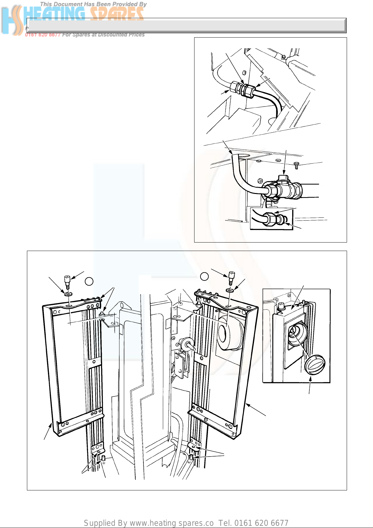
4.1 Positioning the Fire Front (Fitting to 56/3e
and 56/3pp Back Boiler Units ONLY)
Place the wall sealing plate onto the back boiler air duct, mark
the fixing holes, remove the plate and drill the holes to suit the
plugs and screws provided, in the supply tube pack, leave
sufficient screw proud to accept the wall sealing plate keyholes,
see diagram 4.1.
Fit the wall sealing plate and tighten the screws, making sure
that the “wings” are flush with the fire fixing wall face, see
diagram 4.1.
Place the fire front onto the back boiler air duct, check that the
fire front flue spigot is central in the flue collector assembly, push
into contact with the fire front fixing wall face.
Mark the fire front fixing points through the mounting bracket
holes, at the top, see diagram 4.2.
Pull the fire front forwards and remove.
Drill the fire front fixing wall face, using a 10mm masonry drill to
a minimum depth of 40mm to accept the anchor nuts and
screws, supplied in the loose items pack.
Place anchor nuts and screws into holes, screw up, but leave
sufficient thread proud the accept the fire front.
Note. If the fire front fixing face is not of a solid construction, to
a minimum depth of 40mm, that is, hollow brick or metal an
alternative and rigid form of fastening must be used and extra
care taken.
4.2 Securing (Fitting to 56/3e and 56/3pp Back
Boiler Units ONLY)
Refer to diagrams 4.2 and 4.3.
Offer the fire front up to engage fire front spigot, position
mounting bracket holes over the screws in fire front fixing wall
face.
Push back to locate flue spigot into flue spigot duct, lift slightly
to engage mounting bracket onto screws.
Tighten up securing screws.
MARK
FRONT
FIXING
HOLES
MOUNTING
BRACKET (2)
FLUE
COLLECTOR
ASSEMBLY
7868
SPIGOT
FIRE FRONT
Diagram 4.2
7593
G
F
56/3e and 56/3pp
Back Boiler Units ONLY)
FIRE FIXING
WALL FACE
FLUE
SPIGOT DUCT
BACK
BOILER
AIR DUCT
Diagram 4.1
7867
SECURING
SCREW (2)
C
SECURING
SCREW (2)
ANCHOR
NUT (2)
C
D
Diagram 4.3
20221793A
Page 21
Supplied By www.heating spares.co Tel. 0161 620 6677
4 Installation
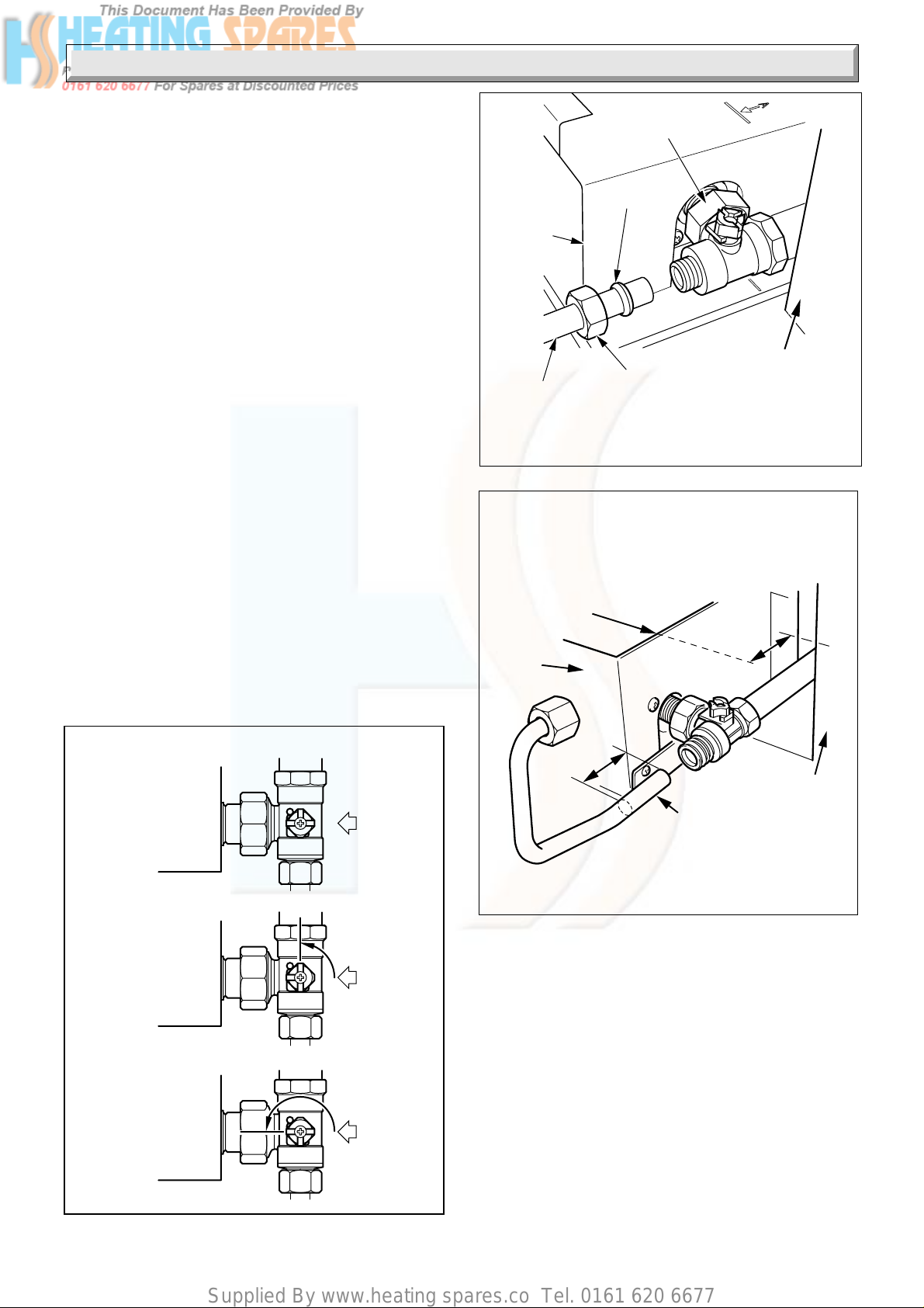
4.3 Gas Connection (Fitting to 56/3e and
56/3pp Back Boiler Units ONLY)
Place the tubing nut and olive, from the loose items pack, onto
the prepared end of the gas supply tube, see diagram 4.9.
Connect the gas supply, as diagram 4.9, tighten the nut and
olive at the gas service cock.
To tighten the other end, use a spanner to hold hexagon locknut
(A) at the bulkhead fitting and make sure that it does not turn,
tighten union nut (B) on the supply tube in the usual manner, see
diagram 4.9.
Make sure that joint (B) is checked for gas soundness, by
checking it when carrying out the other gas soundness checks
as in Section 5.1.
Fit the left hand side panel, see diagram 4.10.
FILTER
SENSING
TUBE
FITTING
ASSEMBLY
3 mm
BACK
BOILER
SENSING TUBE
TUBING
NUT
BULKHEAD CONNECTION
BOILER AIR DUCT
45/2 and 56/2
Back Boiler Units ONLY)
THREAD CUTTING
SCREW(Taptite)
SENSING
TUBE
FITTING
ASSEMBLY
FRONT FACE
OF BOILER
CASTING
Diagram 4.4
4.4 Back Boiler Sensing Tubes (Fitting to 45/2
and 56/2 Back Boiler Units ONLY)
Note: The gas supply tube, see diagram 4.9, is supplied with the
fire. The back boiler sensing tube assembly is packed in the
additional kit no. 459319.
Remove and discard the plastic ferrule, if fitted, from the
bulkhead connection on the Back Boiler air duct.
Fix the flared end of the back boiler sensing tube to the bulkhead
connection on the boiler air duct with the tubing nut provided.
Slide the sensing tube fitting assembly over the back boiler
sensing tube and fix to the casting with the thread cutting screw
(taptite) provided, see diagram 4.4. Fit the sensing tube filter
onto the fitting assembly, see diagram 4.4. Take care not to
damage the filter.
IMPORTANT: Make sure that the sensing tube fitting assembly
is pushed back to the front face of the boiler casting and check
3mm. distance is achieved and back boiler sensing tube does
not extend above sensing tube fitting, see diagram 4.4.
6138
Note: After fitting the flue blockage safety device sensing tube
please refer to the 'Commissioning' section of the back boiler
unit and relight the boiler to test the device.
Check that the gas service cock on the boiler is in the Off
position, see diagram 3.5.
Using a suitable tool break off and discard the shaded section
of wall sealing plate shown in diagram 3.1.
Place the wall sealing plate onto the back boiler air duct, mark
the fixing holes, remove the plate and drill the holes to suit the
plugs and screws provided, in the supply tube pack, leave
sufficient screw proud to accept the wall sealing plate keyholes,
see diagram 4.5.
Fit the wall sealing plate and tighten the screws, making sure
that the “wings” are flush with the fire fixing wall face, see
diagram 4.5.
MARK
FRONT
FIXING
HOLES
SPIGOT
8000
7998
G
F
NOTE:
WINGS
FLUSH
WITH
WALL
Diagram 4.5
21
FLUE
COLLECTOR
ASSEMBLY
FIRE FRONT
Diagram 4.6
221793A
Page 22

Supplied By www.heating spares.co Tel. 0161 620 6677
4 Installation
4.5 Positioning the Fire Front (Fitting to 45/2
and 56/2 Back Boiler Units ONLY)
Place the fire front onto the back boiler air duct, check that the
fire front flue spigot is central in the flue collector assembly, push
into contact with the fire front fixing wall face, see diagram 4.6.
Mark the fire front fixing points through the mounting bracket
holes, at the top, see diagram 4.6.
Pull the fire front forwards and remove.
Drill the fire front fixing wall face, using a 10mm masonry drill to
a minimum depth of 40mm to accept the anchor nuts and
screws, supplied in the loose items pack.
Place anchor nuts and screws into holes, screw up, but leave
sufficient thread proud the accept the fire front.
Note. If the fire front fixing face is not of a solid construction, to
a minimum depth of 40mm, that is, hollow brick or metal an
alternative and rigid form of fastening must be used and extra
care taken.
4.6 Securing (Fitting to 45/2 and 56/2 Back
Boiler Units ONLY)
Offer the appliance up to the back boiler air duct and push back
into position, lift slightly to engage mounting bracket onto
screws, see diagram 4.7.
Tighten the fire front fixing screws, see diagram 4.8.
4.7 Gas Connection (Fitting to 45/2 and 56/2
Back Boiler Units ONLY)
Place the tubing nut and olive, from the loose items pack, onto
the prepared end of the gas supply tube, see diagram 4.9.
Connect the gas supply, as diagram 4.9, tighten the nut and
olive at the gas service cock.
To tighten the other end, use a spanner to hold the locknut (A)
at the bulkhead fitting and make sure that it does not turn,
tighten union nut (B) on the supply tube in the usual manner, see
diagram 4.9.
Make sure that joint (B) is checked for gas soundness, by
checking it when carrying out the other gas soundness checks
as in Section 5.1.
Fit the left hand side panel, see diagram 4.10.
FRONT
FIXING
SCREW
BACK
BOILER
AIR
DUCT
SPIGOT
8001
MOUNTING
BRACKET
C
SECURING
SCREW (2)
ANCHOR
NUT
7874
C
SECURING
SCREW (2)
M5 x 40mm
D
FLUE
COLLECTOR
FIRE FRONT
ASSEMBLY
Diagram 4.7
22221793A
Diagram 4.8
Page 23
Supplied By www.heating spares.co Tel. 0161 620 6677
4 Installation
LOCK
NUT (A)
JOINT (C)
3929 S
UNION
NUT (B)
GAS SUPPLY
PIPE
GAS SERVICE COCK
TUBING
NUT
FIBRE
WASHER
UPPER
SIDE
RETAINING
SCREW
H
LOCATING PIN
AND HOLE
UPPER
SIDE
RETAINING
SCREW
H
FIBRE
WASHER
OLIVE
Diagram 4.9
7588
R.H. SIDE
PANEL
GAS CONTROL
KNOB
L.H. SIDE
PANEL
LOCATING PIN
AND HOLE
23
R.H. SIDE PANEL
LOCATING PIN
AND HOLE
Diagram 4.10
221793A
Page 24
Supplied By www.heating spares.co Tel. 0161 620 6677
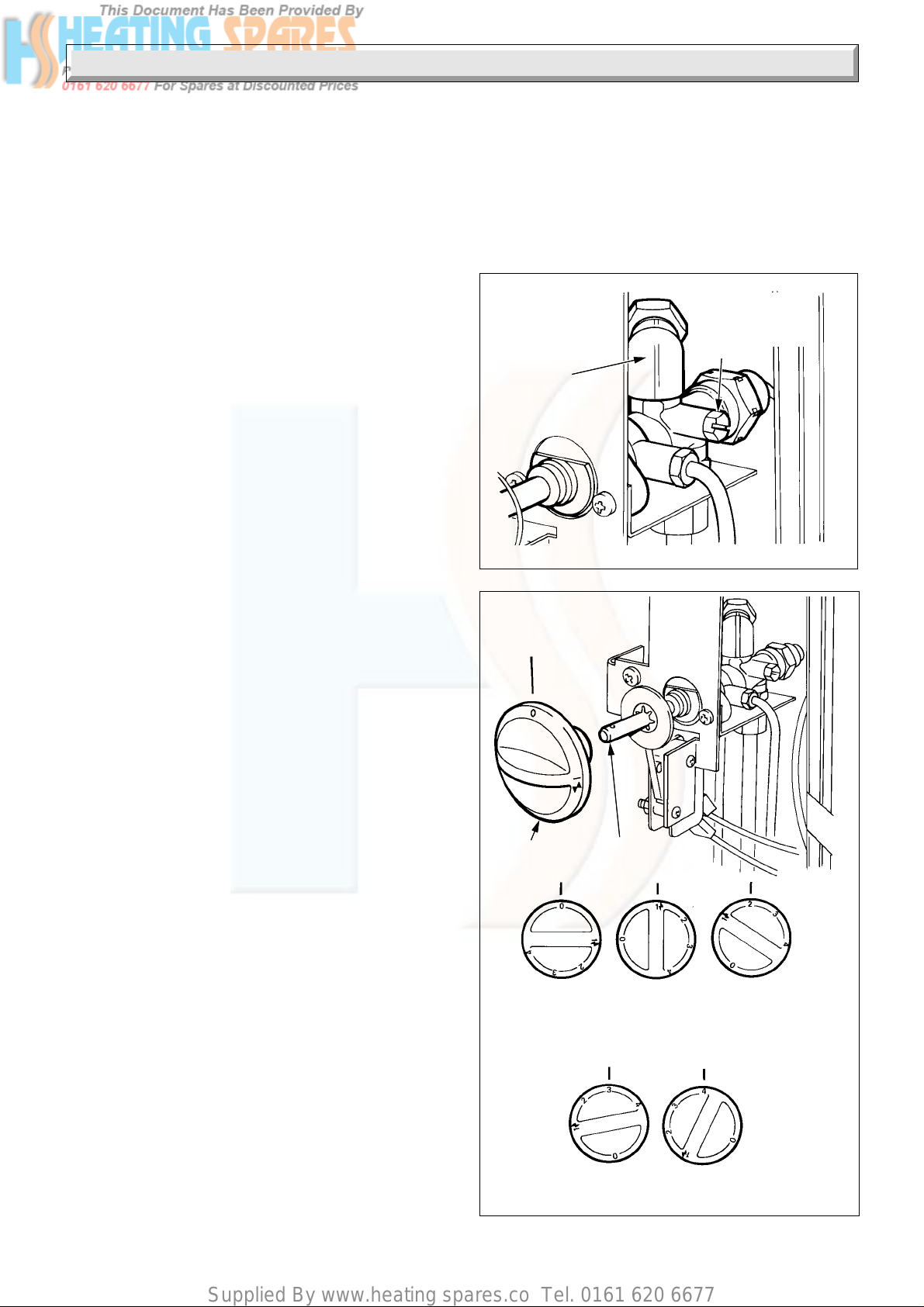
5 Lighting, Testing and Fitting Internal Parts
5.1 Lighting and Testing
Make sure that the electrical supply to the back boiler is isolated.
This fire front is fitted with a flue blockage safety device which
will shut down the fire if there is an unacceptable spillage of
products at the draught diverter. If the fire front shuts down
frequently for no apparent reason the first things to be checked
are the chimney and air inlets into the room. An additional cause
could be that the filter, in the gas tap, has become blocked. Any
problems found must be put right by a competent person before
the fire front is used again.
The flue blockage safety device MUST NOT be adjusted or
disconnected. If replacing use only the correct and approved
parts.
Remove the pressure test nipple screw and fit a suitable
pressure gauge, see diagram 5.1.
Place the right hand side panel onto the pins, see diagram 4.10,
but do not secure at this time.
Turn the gas service cock to back boiler and fire ON, see
diagram 3.5.
Using the pressure drop method check for gas soundness. If
necessary apply a suitable leak detection fluid to all joints,
replace glass panel, see diagram 9 (Instructions for Use).
Fit the control knob to the tap spindle, see diagram 5.2.
IMPORTANT NOTE. If the burner does not light within three
seconds, release the tap, wait ten seconds and repeat the
lighting operation.
Push the control knob fully in and turn it anti-clockwise to 1
- ignition, see diagram 5.2, clicking of the ignition will be heard
and the burner will light.
Keep the knob pushed in for ten seconds, to energise the flame
supervision device, during this time the ignition system will
continue to operate, indicated by the clicking.
Air may be present in the supply to the fire front so that the initial
lighting operation may need to be repeated.
With the burner lit, visually check for leaks whilst changing tap
settings.
To change settings:
0 - 1 Push in and turn
1 - 2 Push in and turn
2 - 3 Push in and turn
3 - 4 Push in and turn
If the burner goes out, wait three minutes before relighting, for
any other reason wait for two minutes.
Check that the gas pressure is as stated in the Data Section 1.3,
or on the Data Label on the left side lower front baffle, see
diagram 5.3.
If there is any doubt about the gas rate, check at the meter,
having first turned off all other gas appliances and pilot lights.
The rate for this fire front, after ten minutes, is about 2.7minutes
3
.
for 1ft
Turn the burner off, remove control knob, release right hand
side panel and pressure gauge, replace the test point screw and
make sure a gas tight seal is made.
Refit, close and secure the side panels, see diagram 4.10.
GAS
TAP
VERTICAL
5082
GAS
CONTROL
KNOB
APPLIANCE
OFF
FLAT DOWN
POSITION
IGNITION &
POSITION 1
PRESSURE
TEST
POINT
Diagram 5.1
POSITION 2
5081
24221793A
POSITION 4POSITION 3
Diagram 5.2
Page 25
Supplied By www.heating spares.co Tel. 0161 620 6677
5 Lighting, Testing and Fitting Internal Parts
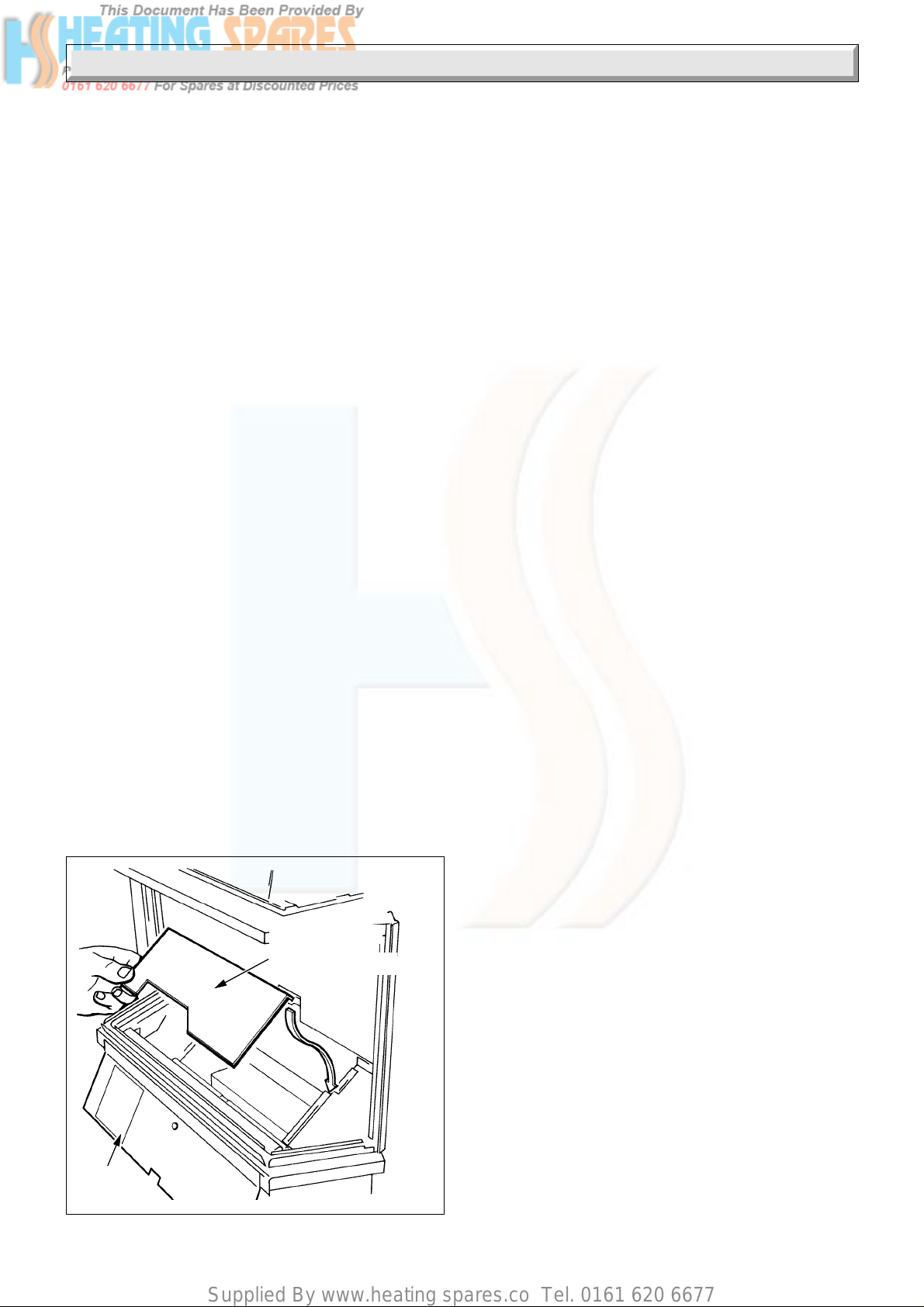
5.2 Internal Parts - Fitting
Caution. If any of the internal fire front parts are damaged DO
NOT light or further test the fire front until replacement parts are
fitted.
Refit gas tap control knob.
Swing the side panels out by about 5mm, to their stops.
Warning. The Glass panel can be hot.
Remove the glass panel, see diagram 9. (Instructions for Use).
Fit the combustion chamber bottom plate (inside base tray), see
diagram 5.3. Follow sequence in diagram 10 to 17. (Instructions
for Use) to fit fuel effect base and internal fire front parts.
Note. The fuel effect pieces are marked on their backs.
Replace front glass panel.
5.3 Decorative Castings
Fit the front legs as diagram 5.4.
Fit the decorative side castings as diagram 5.5, front casing as
diagram 5.6, replace glass panel assembly as diagram 9.
(Instructions for Use) and canopy as diagram 18. (Instructions
for Use).
5.4 Heat Settings
Light the fire front burner as the relevant part of
Section 6.1.
Refer to diagram 5. (Instructions for Use).
At tap position 1 - centre section flame effect.
At tap position 2 - centre section flame effect with
outer sections fuel bed glow.
At tap position 3 - centre and outer sections flame
effect with fuel bed glow.
At tap position 4 - (full on) full flame effect and fuel
bed glow.
In the unlikely event of the flame going out when the fire front
burner is on, then turn off. Wait three minutes before relighting.
If relighting for any other reason, wait two minutes before doing
so.
8055
COMBUSTION
CHAMBER
BOTTOM PLATE
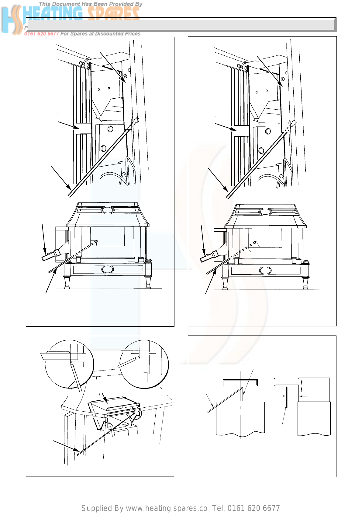
5.5 Test for Clearance of Products
Notes
WARNING. Take care, the appliance will get hot during tests.
For the test you will need a smoke match, extension and a torch.
IN ALL CASES, if spillage continues after the specified test
periods steps must be taken to put the fault(s) right.
Possible causes include, flue obstruction, down draught or
restricted fresh air supply into the room.
If the problem cannot be put right the appliance must be
disconnected and expert advice sought.
Test Where No Fan is Present
Close all outside doors and windows in the room where the
appliance is installed.
Light the fire front only and set tap position to 4. After five
minutes apply a spillage test as shown in diagram 5.7 for the
45/2 and 56/2 or diagram 5.9 for the 56/3. During tests smoke
should be drawn into the fire draught diverter and the boiler
draught diverter.
If spillage occurs, leave the fire front alight for up to a further ten
minutes and repeat test. Turn the fire front burner off.
Next light the back boiler only. After ten minutes apply spillage
test as shown in diagram 5.8 for the 45/2 and 56/2 or diagram
5.10 for the 56/3. During tests smoke should be drawn into the
fire front draught diverter and boiler draught diverter.
If spillage occurs, leave the back boiler alight for up to a further
five minutes and repeat tests.
Leave the back boiler alight.
Now light the fire front. After ten minutes apply spillage tests as
shown in diagram 5.7 and 5.8 for the 45/2 and 56/2 or diagrams
5.9 and 5.10 for the 56/3. During tests smoke should be drawn
into the fire draught diverter and boiler draught diverter.
If spillage occurs leave back boiler and fire front alight for up to
a further five minutes and repeat tests.
Test Where a Fan is Present
A fan means an extract fan or a fan for other open flued
appliances or a circulating fan for a warm air unit, whether or not
gas fired. With the fan switched off carryout the appropriate
spillage test with all doors and windows closed, as Test Where
No Fan is Present.
If the above spillage test is satisfactory carry on as follows:
Open all doors connecting the room containing the appliance
and the room in which the fan is fitted.
Close all other doors and windows in the premises.
If the fan is in the same room as the appliance, close all doors
and windows in that room.
Switch the fan on and repeat the spillage test as above.
5.6 Plinth Fitting
Fit the controls cover plinth onto the guides and push it back as
far as it will go, see diagram 3. (Instruction for Use).
DATA
LABEL
Diagram 5.3
25
221793A
Page 26

Supplied By www.heating spares.co Tel. 0161 620 6677
5 Lighting, Testing and Fitting Internal Parts
LEG
SECURING
E
SCREW (2)
FOOT
LEVELLING
SCREW
Diagram 5.4
A
7564
3944S
LOCATION PIN
LOCATION
SLOT
VIEWED FROM REAR
3945S
SECURING
B
SCREW (3)
M5 x 14mm
SIDE CASTING
FRONT
CASTING
Diagram 5.6
Diagram 5.5
26221793A
Page 27
Supplied By www.heating spares.co Tel. 0161 620 6677
5 Lighting, Testing and Fitting Internal Parts
10mm
40/
45mm
15mm to right of centre
SMOKE
MATCH
AND
EMPLUME
TUBE
EMPLUME
TUBE
FRONT VIEW
SIDE VIEW
HEA T
EXCHANGER
L.H. SIDE
PANEL
SMOKE
MATCH
AND
EMPLUME
TUBE
DRAUGHT
DIVERTER
7876
L.H. SIDE
PANEL
SMOKE
MATCH
AND
EMPLUME
TUBE
DRAUGHT
DIVERTER
7879
TORCH
SMOKE MATCH
AND EMPLUME
TUBE
(45/2 and 56/2 ONLY)
10
10
SIDE VIEW
25
25
DIVERTER
PLATE
Diagram 5.7
10
FRONT VIEW
5176
TORCH
SMOKE MATCH
AND EMPLUME
TUBE
(56/3e and 56/3pp ONLY)
60
Diagram 5.9
7909
560 SMOKE
MATCH
AND
EMPLUME
TUBE
(45/2 and 56/2 ONLY)
FIRE SPIGOT NOT
SHOWN FOR CLARITY
Diagram 5.8
(56/3e and 56/3pp ONLY)
27
Diagram 5.10
221793A
Page 28

Supplied By www.heating spares.co Tel. 0161 620 6677
6 Instructions for Use
Hand these instructions the user and instruct in the safe and
economical use of the fire front and back boiler.
Advise the customer that they should read their Users
instructions before operating the fire and always follow the
advice in the Section headed “Cleaning your Fire”.
Advise that any smell which may be apparent on initial lighting
is quite normal and it will quickly disappear.
Important: Advise that soft wall coverings, for example, blown
vinyl wallpaper, are easily affected by heat, they may, therefore,
scorch or become discoloured when close to a heating appliance.
This should be borne in mind when having a heating appliance
installed and when redecorating.
Advise the user, to ensure the continued efficient and safe
operation of the appliance it is recommended that it is checked
and serviced as necessary at regular intervals. The frequency
of servicing will depend upon the particular installation and
usage, but in general once a year should be enough.
Draw attention, if applicable, to the current issue of the Gas
Safety (Installation and Use) Regulations, Section 35, which
imposes a duty of care on all persons who let out any property
containing a gas appliance.
It is the Law that servicing is carried out by a competent person.
Show how to light the fire front, in the event of a power or ignition
system failure, with a spill or long match.
Remove the front casting.
Hold a lighted spill or long match and insert it beneath the front
lighting assembly, position the spill so that the flame is over the
burner, see diagram 6.1.
Keep the spill in position, push in and turn the gas tap to position
1 and the burner will light keep knob pushed in for about 10
seconds and the burner will stay light.
If the burner should go out repeat the above operation, but now
keep the knob pushed in for a little longer.
Once lit operate the gas tap normally.
This is a temporary measure only and the fault must be put right
as soon as possible.
Advise the user of the precautions necessary to prevent damage
to the system, boiler and the building, in the event of the heating
system being out of use during frost or freezing conditions.
Advise that the fire front is fitted with a safety device and refer
to the instructions for use.
Reminder, leave these instructions with the user.
Advise the user that the ‘Benchmark’ logbook should be
completed by the installation engineer on completion of
commissioning or servicing.
MATCH OR
EXTENSION
BURNER
MATCH OR
SPILL
Diagram 6.1
7432
7 Servicing and Replacement of Parts
3 Flue Systems
Notes
To ensure the continued efficient and safe operation of the
appliance it is recommended that it is checked and serviced at
regular intervals. The frequency of servicing will depend upon
the particular installation and usage, but in general once a year
should be enough.
It is the Law that servicing is carried out by a competent person.
Make sure that the fire is cold before carrying out any servicing.
After servicing, or replacing parts, always test for gas soundness
with a suitable leak detection fluid. To test the gas tap, refix the
fire front and apply leak detection fluid to all joints, replace the
glass panel, light the burner and visually check all joints for
leakage whilst changing tap settings.
Carry out functional check on controls, see Section 4 and 5.
Other than for replacing the glass panel, internal fire front parts
and lighting the fire front should be removed from its fixings by
reversing the instructions in Section 4 and 5. Make sure that
the side panels and feet are removed. Refit controls cover plinth
so that the fire can stand upright.
Unless stated otherwise reassembly all parts in the reverse
order to removal.
The back boiler should be serviced at this time, refer to Back
Boiler Installation and Servicing Instructions.
The flue blockage safety device MUST NOT be adjusted or
disconnected. If replacing use only the correct and approved
parts.
7.1 Glass Panel
Lift canopy off, see diagram 18. (Instructions for Use). Take care
as it is made of cast iron.
Swing open side panels to their stops, about 5mm, as diagram
8 (Instructions for Use).
To remove the glass panel, refer to diagram 9. (Instructions for
Use).
7.2 Internal Fire Front Parts
Remove internal fire front parts as diagrams 17 to 10. (Instructions
for Use).
Examine these parts and replace as necessary.
28221793A
Page 29

Supplied By www.heating spares.co Tel. 0161 620 6677
7 Servicing and Replacement of Parts
4854
LOWER
FRONT
BAFFLE
SECURING SCREWS (3)
SECURING SCREWS (2)
BURNER
BAFFLE
7.3 Burner and Injectors
Remove the front casting, see diagram 5.6.
Remove the lower front baffle, see diagram 7.1.
Remove the burner baffle, see diagram 7.1.
Remove the RH. leg, see diagram 5.4.
Remove the side castings, see diagram 5.5.
Remove the RH. leg support bracket, see diagram 7.2.
Disconnect the supply pipe unions at the injectors also the union
connection at the front, see diagram 7.3.
Remove the two burner securing screws, see diagram 7.3.
Swing the burner out for access, see diagram 7.4.
Unscrew the injectors, inspect, clean or replace as necessary,
see diagram 7.5.
Do not clean the holes with a wire or sharp instrument.
Remove injector box cover screw and plate, see diagram 7.5,
clean out dust and debris. Brush away any lint and dust from the
burner and surrounds. Using a soft brush or vacuum cleaner.
Do not use a brush with wire bristles.
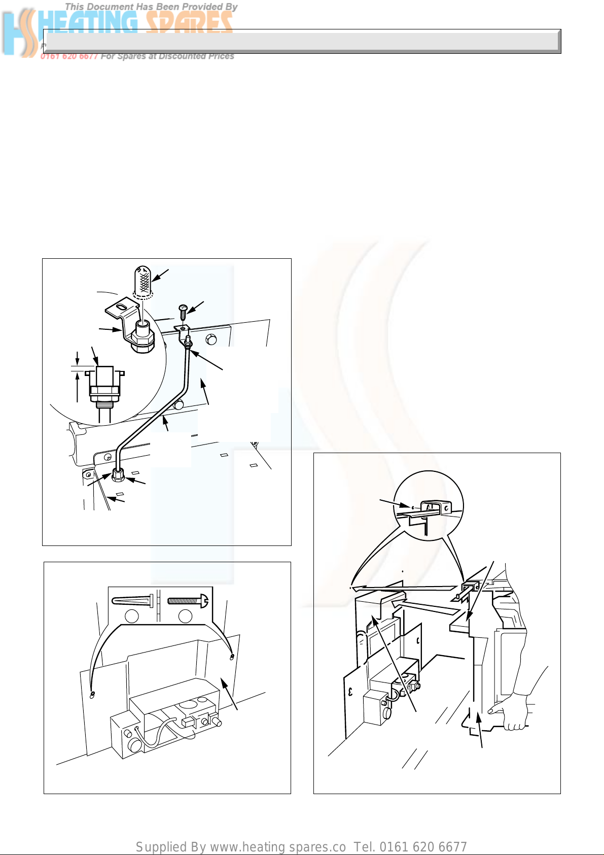
7.4 Flue blockage safety device
Remove the burner, refer to Section 7.3.
Check the condition of the electrode and thermocouple, clean
with a soft brush, see diagram 7.7.
Make sure the electrode is in line with the earth post and spark
gap is as in diagram 7.7.
7.5 Ignition Lead
Remove the burner, refer to Section 7.3.
Disconnect the tube nuts, remove the mounting bracket securing
screws and flue blockage safety device, see diagram 7.6.
Check the ignition lead, see diagram 7.7. Replace if required,
refer to Section 9.5.
Note. When refitting the flue blockage safety device, take care
not to trap the ignition lead under the mounting bracket.
7.6 Gas Tap and Micro Switch Assembly
Note. This item need not be serviced annually.
Remove micro switch electrical connections, see diagram 7.8
Disconnect all union connections and remove the tubes in the
order shown in diagram 7.9.
Take care as the filter in the pilot port may be loose, see diagram
7.11.
Disconnect the thermocouple nut, see diagram 7.10.
When replacing only tighten the nut a quarter turn beyond finger
tight.
Remove the gas tap bracket securing screws, see diagram
7.11.
Remove the gas tap assembly.
To service the gas tap remove the gas tap niting plate assembly
securing screws, see diagram 7.11. Take care as there is a
spring beneath the niting plate. Remove the plug, pin, spring
washer, plain washer and “O” ring, see diagram 7.11.
Clean and relubricate using a suitable grease.
When replacing make sure the operating disc, with retaining
washer and micro switch leads are correctly located, see
diagram 7.8 and 7.11.
29
Diagram 7.1
5080
Diagram 7.2
221793A
Page 30

Supplied By www.heating spares.co Tel. 0161 620 6677
7 Servicing and Replacement of Parts
L.H. BURNER
SECURING SCREW
BURNER
UNION
UNION CONNECTION
CONNECTION
NOTE:
Chamfered edge to be on
this side.
R.H. BURNER
SECURING SCREW
UNION
CONNECTION
Diagram 7.3
4855
7878
TUBE
NUT
FLUE BLOCKAGE
SAFETY DEVICE
INJECTOR BOX
COVER
BURNER
PULL FORWARDS
Diagram 7.4
5172
MOUNTING
BRACKET
SECURING
SCREW (2)
3958 S
SECURING
SCREW
INJECTORS
Diagram 7.5
30221793A
SECURING
SCREW (2)
IGNITION
LEAD
Diagram 7.6
Page 31

Supplied By www.heating spares.co Tel. 0161 620 6677
7 Servicing and Replacement of Parts
EARTH
POST
ELECTRODE
ELECTRODE
C
L
SPARK GAP
+ 1.0
3
- 0.5
EARTH
POST
5248
GAS TAP MOUNTING
BRACKET SECURING
SCREW
MICRO SWITCH
ELECTRICAL
CONNECTIONS
INSULATION
3960 S
MICRO
SWITCH
ELECTRODE
67
TOP VIEW
18
EARTH
POST
Diagram 7.7
NUT (2)
INSULATION
SECURING
SCREW (2)
GAS TAP
MOUNTING
BRACKET
Diagram 7.8
31
221793A
Page 32

Supplied By www.heating spares.co Tel. 0161 620 6677
7 Servicing and Replacement of Parts
1
8
6
9
5
7
4
5089
2
GAS TAP SECURING
SCREWS
3
5090
9
5
THERMOCOUPLE
7
GAS TAP
BRACKET AND
NITING PLATE
ASSEMBLY
Diagram 7.9
GAS TAP
BODY
PLUG
'O' RING
WASHER
SPRING
GAS TAP
BODY
NUT
Diagram 7.10
5091
FILTER
FILTER
CROSS
SECTIONAL
VIEW
SECURING
SCREW
32221793A
Diagram 7.11
Page 33
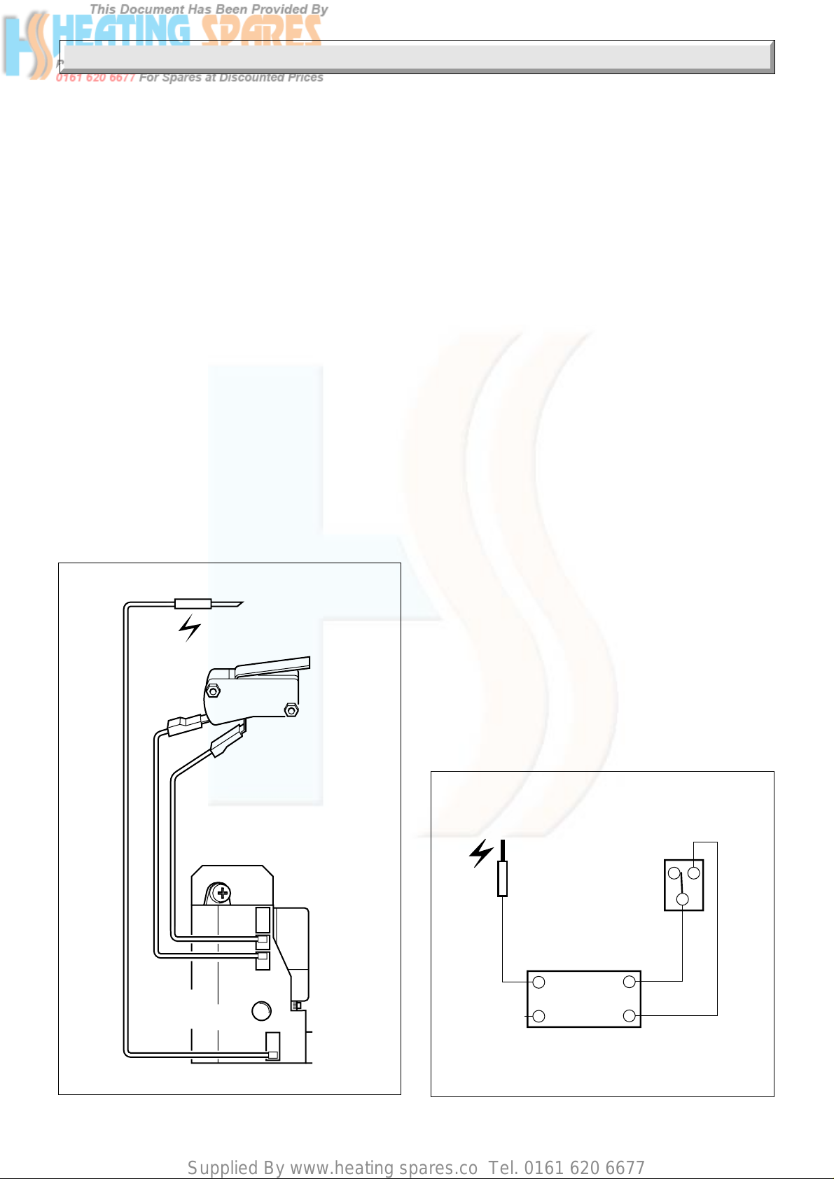
Supplied By www.heating spares.co Tel. 0161 620 6677
8 Fault Finding
8.1 Fire Front Ignition
Remove decorative castings, glass panel and fuel bed, refer to
appropriate parts of Section 7. Refit glass panel.
Refer to diagram 8.3.
8.2 Electrical
Refer to functional flow diagram 8.2 and pictorial wiring
diagram 8.1.
8.3 Thermocouple
To test a thermocouple, a meter with a range of 0 to 30mV is
required together with a thermocouple interrupter test unit,
similar to the British Gas Minitest 6 unit.
Refer to fault finding diagram 8.4 and diagnosis graph,
diagram 8.5.
8.4 Flue blockage safety device
If the device operates it indicates there could be a problem with
the chimney or, the pilot filter in the gas tap is blocked. First
make sure air vents are free from obstructions, by carrying out
spillage checks as Section 5.5. If all is in order refer to diagram
8.3 to check if the pilot filter is blocked.
Notes.
Make sure that the fire is cold before replacing any parts.
Replacement of parts must be carried out by a competent
person.
Remove the internal fire front parts as the relevant part of
Section 5.2.
ELECTRODE
RED
RED
SPARK
GENERATOR
5251
MICRO
SWITCH
5252
ELECTRODE
MICRO
SWITCH
SPARK GENERATOR
RED
RED
Diagram 8.1
33
Diagram 8.2
221793A
Page 34

Supplied By www.heating spares.co Tel. 0161 620 6677
YES
START HERE
Turn off appliance tap,
turn on appliance tap.
Does the fire light ?
NO
8 Fault Finding
FIRE WILL NOT LIGHT
Check that gas is available
Does the pilot light using a match ?
YES
5478
NO
Change pilot filter
Ensure gap is within specified
tolerance, refer to SERVICING.
turn tap to energise ignition.
Does the fire light ?
YES
NO
Disconnect ignition lead from
electrode, place connector
within 4mm of burner and turn
tap to energise igniter. Is there
a spark at the gap ?
YES
Replace faulty electrode and
reassemble ignition system.
Turn tap to energise igniter.
Does the fire light ?
NO
YES
Disconnect red leads from ignition
unit. Turn tap to energise ignition. Is
there continuity between red leads ?
Check that gas is available at burner, using a
match, ensuring correct functioning of burner
on all setting positions. Check that electrode,
micro switch and ignition unit connections are
satisfactory. Check that burner pressure is as
specified - correct any fault found.
NO
Remove ignition lead from ignition unit and
place screw driver between appliance chassis
earth and ignition unit, leaving 4mm gap
between blade and spade connector. Turn tap
to energise ignition. Is there a spark at gap ?
NO
YES
Renew ignition lead and
reassemble ignition system.
YES
Change the ignition unit battery.
Turn tap to energise ignition.
Does the fire light ?
YES
NO
Change ignition unit.
Check several times that ignition is satisfactory.
34221793A
NO
Rectify faulty leads or
replace micro switch.
Diagram 8.3
Page 35
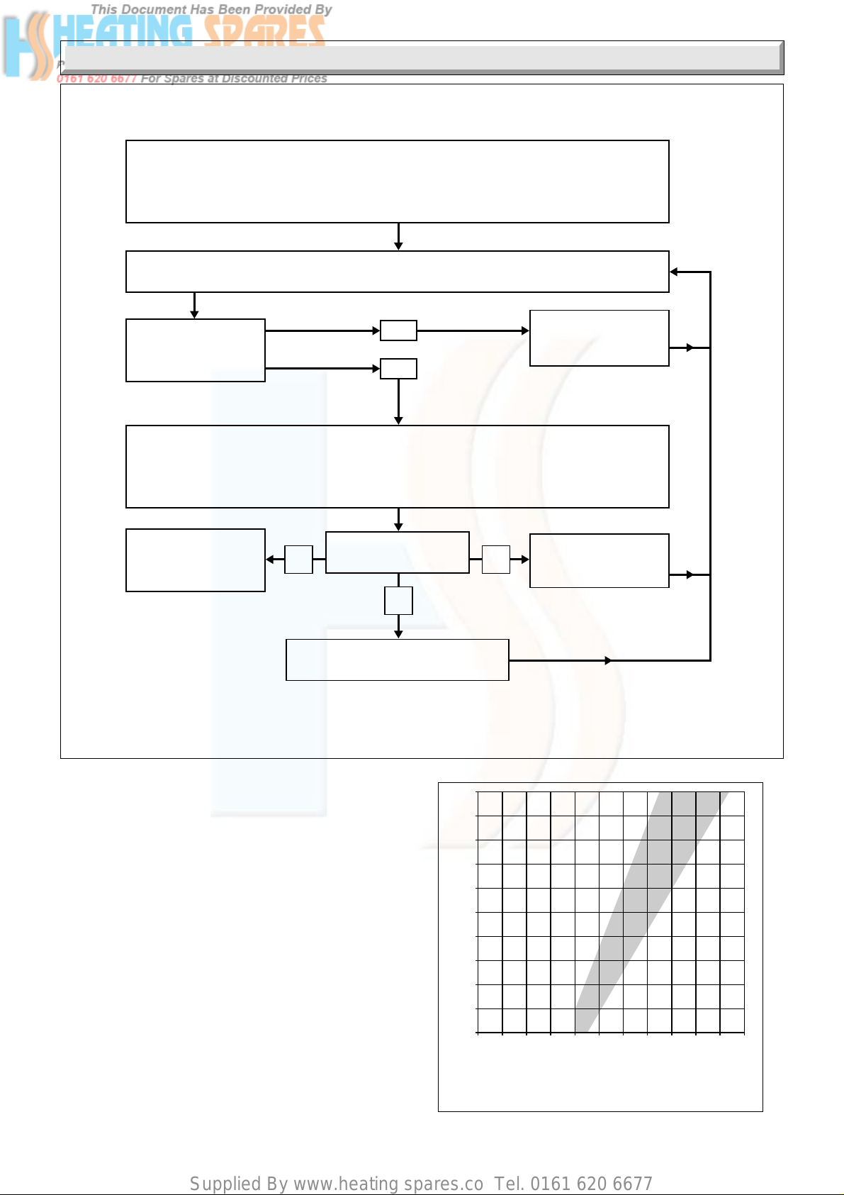
Supplied By www.heating spares.co Tel. 0161 620 6677
8 Fault Finding
Disconnect appliance thermocouple from the gas tap. Check that all connections are
clean and in good condition. Fit test meter interrupter into the magnet unit. Fit appliance
thermocouple into the test meter interrupter.
Hold down control tap in ignition position. Ignite burner, allowing thermocouple to attain
operating temperature. Measure the OPEN CIRCUIT voltage.
7633
Is voltage greater
than 15mV?
Note the open circuit reading then measure the CLOSED CIRCUIT voltage. Note this voltage.
Referring to the diagnosis graph, mark the open circuit voltage on the VERTICAL axis,
and the closed circuit voltage on the HORIZONTAL axis. Note the point where these
two values intersect on the graph.
THERMOCOUPLE
CIRCUIT IS
SATISFACTORY
In which area of the
graph is the intersect
B
Faulty magnet unit in gas tap.
Replace gas tap
NO
YES
A
C
Faulty thermocouple.
Replace flue blockage
safety device.
Faulty thermocouple.
Replace flue blockage
safety device.
17
16
15
14
13
12
11
10
9
8
Open Circuit Voltage (millivolts)
7
01234567891011
Closed Circuit Voltage (millivolts)
DIAGNOSIS GRAPH FOR FIRE
THERMOCOUPLE CIRCUIT
35
Diagram 8.4
0065M
ABC
Diagram 8.5
221793A
Page 36
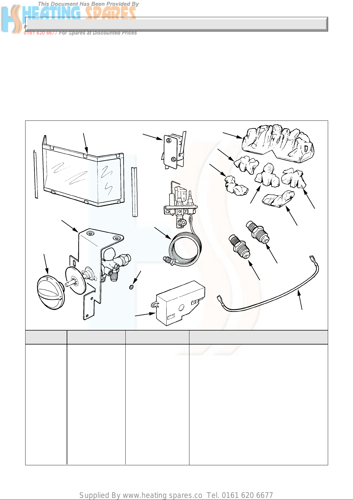
Supplied By www.heating spares.co Tel. 0161 620 6677
9 Replacement Parts
Before removing or replacing any fire front parts turn the gas supply service cock to “Back Boiler Only On”, see diagram 3.5.
Isolate the electrical supply to the back boiler and fire front.
After replacing or disconnecting any gas carrying components, always test for gas soundness, using a suitable leak detection fluid
and carryout functional check of controls.
To test the gas tap apply leak detection fluid to all joints, light the burner and check all the joints for leakage at all tap settings.
Unless stated otherwise reassembly of all parts is in the reverse order to removal.
When replacement of parts are required please apply to your local supplier.
Please quote the name of the fire front, “Black Ash 3 BBU”.
The GC number can be found on the chassis, visible when front casting is removed.
Refer to diagram 9.1 for the illustration of the replacement parts.
13
14
7
11
1
7966
5
3
2
6
16
10
8
4
9
15
12
Diagram 9.1
Key No. Part No Part No.G.C.. Description
1 210213 136 918 Rear fuel effect piece
2 210214 136 919 Fuel effect piece - 1
3 210215 136 920 Fuel effect piece - 2
4 210216 136 921 Fuel effect piece - 3
5 210217 136 922 Fuel effect piece - 4
6 210218 136 923 Fuel effect piece - 5
7 448093 136 924 Glass panel assembly
8 230169 398 444 Injector - upper
9 230201 398 422 Injector - lower
10 203437 162 100 Flue blockage safety device
11 202014 360 188 Microswitch
12 WW4617 312 997 Ignition lead
13 448103 136 925 Gas tap control knob
14 800449 136 927 Gas tap
15 202179 152 949 Spark generator
16 208673 162 208 Filter
Because of our constant endeavour for improvement details may vary slightly from those in the instructions.
36221793A
 Loading...