

Page 1
318504
Operation Manual
Contents subject to change without notice
Version 1.0
Issue AA
Page 2
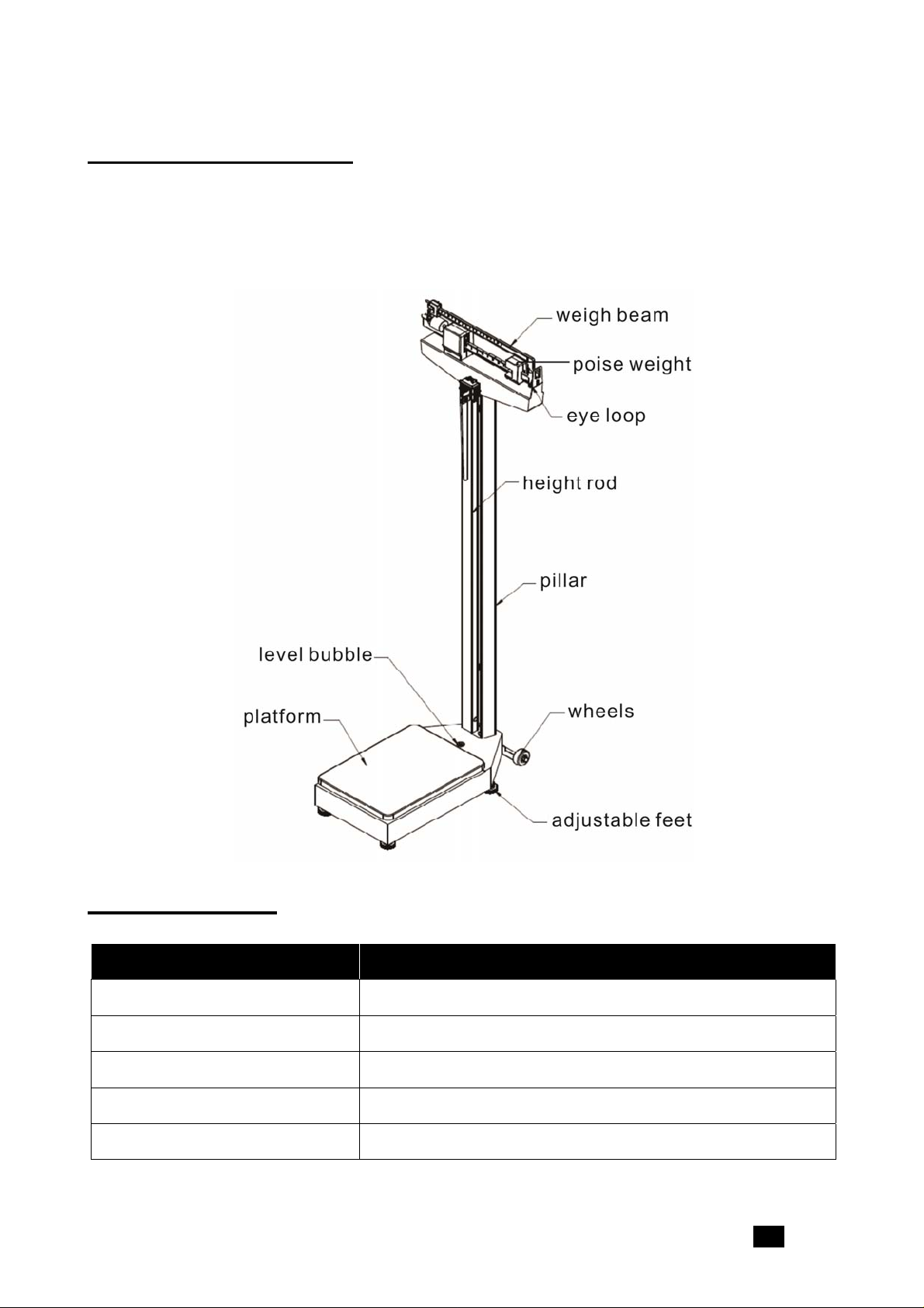
General Information
The 318504 Mechanical Physician Scale is ideal for use in health clinics and medical
practices for height and weight measurement. The scale is durable, having a sturdy
enameled steel body, removable slip-resistant plastic cover, a retractable aluminum height
rod, and rear wheels.
Specifications
Model 318504
Max Capacity 450lb
Weight Graduation 0.25lb
Height Measurement Range 24-84”
Height Graduation 0.125”
Platform Size 14.75” x 10.75”
318504 www.globalindustrial.com . 1 .
Page 3
Assembly
The 318504 Mechanical Physician Scale comes partially assembled. The following
components require assembly:
Pillar
Steel connection rod
Height rod
Wheels
Tools required:
Phillips head screwdriver
Wrench (included)
1. Set the scale base on a table or other assembly area free from traffic and obstructions.
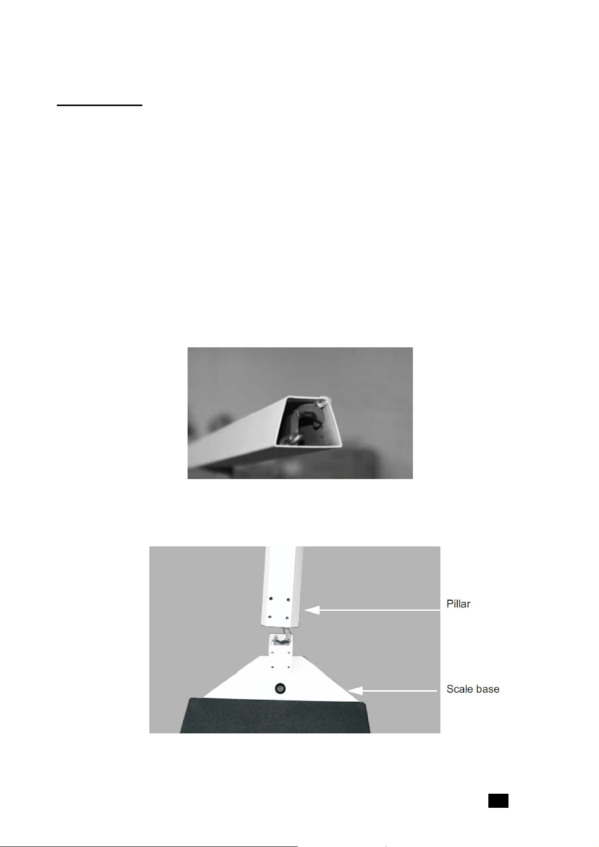
2. Remove the tie that secures the steel rod during transit (shown in Figure 1).
Figure 1. Remove Cable Tie
3. Insert the pillar into the scale base (shown in Figure 2), ensuring that the Global logo on
the weight beam faces the scale base.
Figure 2. Attach the Pillar to the Scale Base
318504 www.globalindustrial.com . 2 .
Page 4

4. Using a Phillips screwdriver, screw in the eight bolts and washers to secure the pillar to
scale base as shown in Figure 3.
Figure 3. Attach Eight Bolts and Washers to Secure the Pillar to the Base
5. Lay the scale on a table. Remove and discard the shipping tie wrap wires on the
underside of the scale carriage as shown in Figure 4.
Figure 4. Lay Scale on Table to Access Bottom of Scale
6. Insert the wrench (included) into the small hole in front of the steel rod and pull the rod
hook with the wrench to connect it to the scale base as shown in Figure 5. The steel rod
is located inside the scale pillar. Once the pillar is attached to the scale base, the steel
rod must be attached to the bottom of the scale.
318504 www.globalindustrial.com . 3 .
Page 5

Figure 5. Connect the Steel Rod to the Scale Base
7. Push the long lever forward and hook the steel rod’s bearing on the long lever pivot.
NOTE: During shipping, a plug is installed to ensure that the force lever assembly stays
aligned, but the linkage may still come out of alignment. Visually ensure that the force lever
assembly linkage is centered and properly aligned. The linkage must be free floating in order
for the scale to weigh properly. If the scale is slightly tipped to one side, the linkage can be
seen by looking up underneath the top weigh beam.
Figure 6. View of Linkage Underneath the Top Weigh Beam
8. Place the scale gently back on the floor.
318504 www.globalindustrial.com . 4 .
Page 6

Height Rod Assembly
1. Insert the slotted holes on the back of the height rod into the two bolts on the front of the
pillar as shown in Figure 7.
2. Use the enclosed wrench to tighten the two hex-head screws. Be sure not to
over-tighten.
3. To raise or lower the height rod, press the red button at the top of the height rod.
Figure 7. Attach the Slotted Screw Location onto the Pillar Bolt Location
318504 www.globalindustrial.com . 5 .
Page 7

Wheel Assembly
Mounting the wheels upside down can cause weighing errors.
1. Align the angle iron of the wheel base to the scale platform as shown in Figure 8.
2. Use the screws and washers that are included to affix the wheel assembly to the
platform. Adjust the angle iron at a level position and then tighten screws.
3. When moving the scale, hold the two side faces of the pillar to keep the front side of the
platform away from the ground.
Top
Bottom
Figure 8. Attach the Scale Wheels onto the Scale Base
318504 www.globalindustrial.com . 6 .
Page 8

Zero Adjustment
After assembly, the scale must be zeroed prior to use.
1. Ensure the scale is sitting on a level surface and slide the upper and lower weights
to the far left positions.
2. Gently hold the scale pointer with your finger so it is centered within the eye loop
area. Release the scale pointer and let it rise freely up or down.
3. If the pointer doesn’t remain centered, turn the zero adjustment screw (shown in
Figure 9) using a flathead screwdriver until the pointer remains centered within the
eye loop.
Zero
adjustment
screw
Weigh beam
Scale pointer
Eye loop area
Figure 9. Eye Loop Area and Zero Adjusting Screw Location (shown without height rod)
318504 www.globalindustrial.com . 7 .
Page 9

Troubleshooting
The Mechanical Physician Scale is factory-calibrated to within plus or minus 1/4 pound
accuracy. For the most accurate readings, always use the scale on a hard, level surface
and stand in the center of the scale platform with the weight evenly distributed. If an error
occurs or seems excessive, check the following:
Problem Possible Solution
Zero balance out of
adjustment
Beam does not move
freely
Platform rocks
excessively
Beam does not move at
all during weighing
The weighing beam must be balanced so the pointer comes
to a rest in the center of the eye loop (shown in Figure 9)
when both poise weights are set at zero (see page 1 for
poise weight location). Follow zero adjustment instructions
on page 7.
Make sure the pointer is not touching the side of the eye
loop, impeding its range of travel.
Visually ensure that the linkage is centered and properly
aligned. Occasionally during shipping, the alignment will
become skewed. The linkage must be free floating in order
for the scale to weigh properly. If the scale is slightly tipped
to one side, the linkage can be seen by looking up
underneath the top weigh beam.
Ensure scale is setting on a level surface. When you push
down on any corner of the platform, you should not feel any
significant rocking.
Weights are set higher than the person’s actual weight.
Reset the weights to a lower weight.
Make sure steel rod is properly connected and aligned as in
Figure 5.
Scale is out of
calibration
318504 www.globalindustrial.com . 8 .
Recalibrate the scale by placing a known weight on the scale
and turning the zero adjustment screw until the pointer
remains centered within the eye.
11 Harbor Park Drive Port Washington, NY 11050
 Loading...