

globalindustrial.ca
User's manual Manual del usuario Manuel de l'utilisateur
Distribucion Industrial Globales S DE RL DE CF
Customer Service
US: 1-800-645-2986
Servicio de atención al Cliente
México: 01.800.681.6940
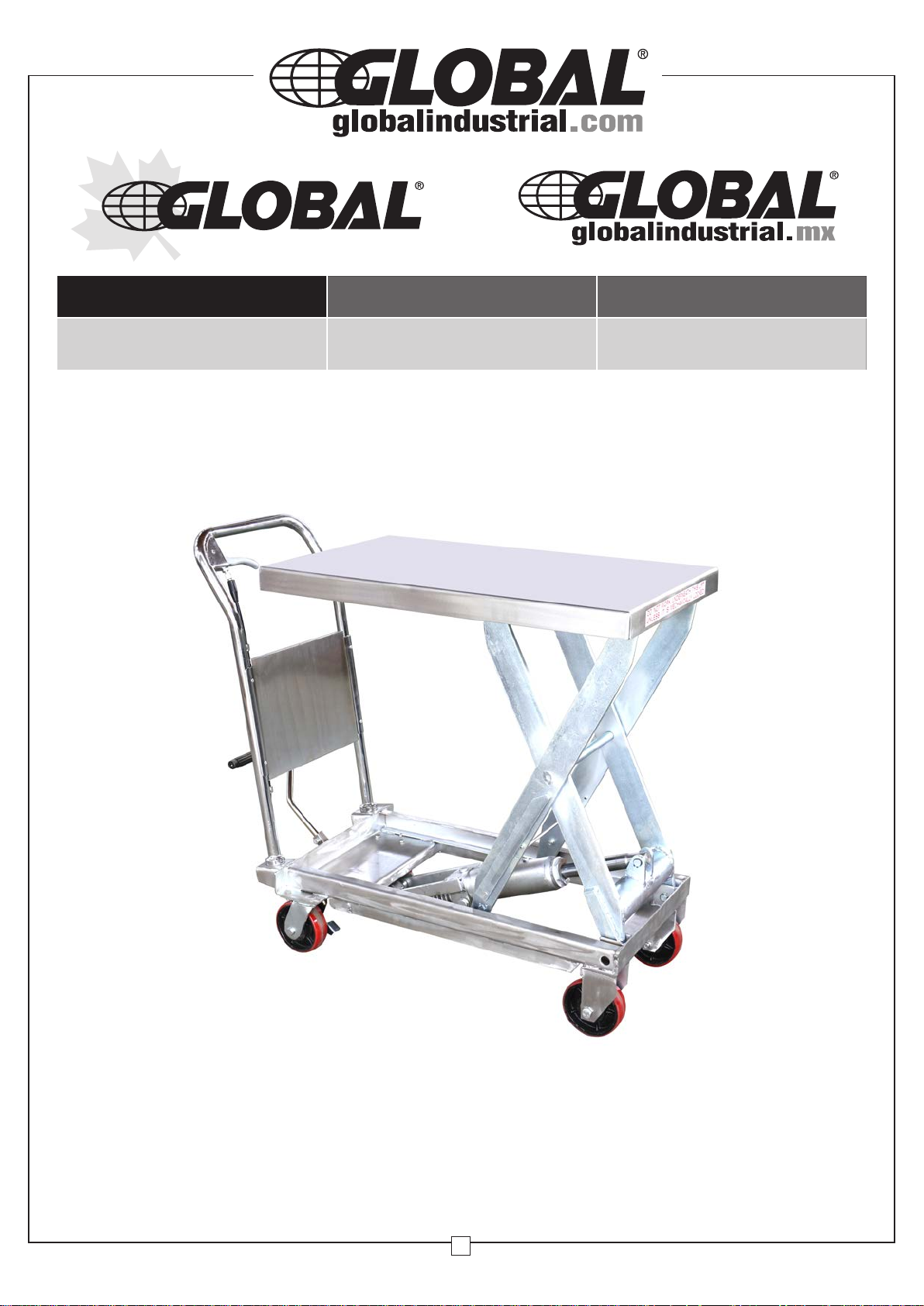
Lift Table
Model 989011
Service à la clientèle
Canada: 888-645-2986
Note: Owner and operator MUST read and understand
these operating instructions before using this lift table.
1
Lift Table
TABLE OF CONTENTS
Warnings........................................................ 2
1.
2. Daily Inspection ............................................ 3
3.
Operating Lift Table ..................................... 3
4. Specifications............................................... 4
5. Service Instructions ..................................... 4
Part List of Table .......................................... 5
6.
7. Part List of Pump............................................ 6
User’s Manual
ou fo
Thank y
is designed for the lifting and horizontal transport of loads on a level, fixed base. For
your safety, please carefully read this instruction manual before using it and keep it
on file for future reference.
NOTE: All of the information reported herein is based on data available at the moment of
printing. We reserve the right to modify our own products at any moment without notice and
incurring in any sanction. So, it is suggested to always verify possible updates.
r using this lift table. Your lift table is made of high quality steel and
1. WARNINGS
1、 DO NOT put foot or hand in scissors mechanism.
2、 DO NOT allow other person to stand in front or behind lift table when it is moving.
3、 DO NOT move lift table when table is in raised position. Load could fall down.
4、 DO NOT
5、 DO NOT overload lift table.
6、 DO NOT put foot in front of rolling wheels.
7、 WATCH difference of floor level when moving lift table. Load could fall down.
8、 DO NOT use lift table on slope or inclined surface, lift table may become
uncontrollable and create danger.
9、 DO NOT lift people. People could fall down and suffer severe injury.
10、 Read this operation manual carefully before operating lift table. Improper operation
can be dangerous.
11、 This lift t
NOT use lift table for purposes other than its intended use.
12、 Only allow operators who have read and understand the instructions to operate the
lift table
13、 DO NOT lower t
14、 KEEP watching the condition of load. Stop operating lift table if load
enter under table.
able is a movable lifter designed to lift or lower rated load on table. DO
able too fast. Load co
uld fall down
and cause injury.
2

Lift Table
becomes unstable.
15、 Apply brakes when sliding load on or off table.
16、DO NOT side or end load. Load must be distributed evenly across table area.
17、 DO NOT use lift table with unstable or unbalanced load.
18、 Practice maintenance work according to service instructions.
19、DO NOT modify lift table without manufacturers written consent.
20、REMOVE load from table and use safety stopper to prevent table from lowering
when servicing lift table.
21、This lift table is not designed to be water resistant.Use lift table under dry conditions.
2. DAILY INSPECTION
Daily inspection is effective for preventing injuries caused by product damage.
Check lift table on the following points before operation .
(1) Check for scratches, bending or cracking on the lift table.
(2) Check if there is any oil leakage from the cylinder.
(3) Check for vertical creep of the table.
(4) Check the smooth movement of the wheels.
(5) Check the brake function.
Check that
(6)
CAUTION: DO NOT use lift table if any malfunction or fault is found.
all the bolts
and nut
s are tigh
tened firmly.
User’s Manual
3.
OPERATING LIFT TABLE
3-1. How to use the brake.
CAUTION: Use brakes when the lift is stationary to prevent sudden movement.
The brake is equipped with a swivel caster on one side.
(1) To apply the brakes, press the brake pedal down.
(2) To release the brakes, lift the brake pedal up.
3-2.Lifting the table
WARNING
1. DO NOT overload lift table. Stay within its rated capacity.
2.
DO NOT side or end. Load must be dist
Press the lifting pedal several times until the table reaches the desired position. The table
does not elevate after reaching the highest position even if the lifting pedal is pressed. The
table lowers slightly after reaching the highest position.
MAXIMUM CAPACITY OF TABLE
989011
1100 lbs
NOTE: The hydraulic cylinder is designed to hold table. As is the nature of
hydraulic systems, table lowers very slowly over an extended period of time. Please note
the table does not stay at the same position indefinitely.
ributed evenly across table area.
3. To lower the table, pull the control handle.
3

4.
Specifications
Model
Capacity
(lbs)
Table
(in)
Lift Table
Table
Height (in)
Wheel
(in)
User’s Manual
Weight
(lbs)
989011 1100
5.
Service Instructions
5-1. Change hydraulic oil every 12 months.
5-2. Lubricate each point described below every month:
(1) Fitting of cylinder---Oil
(2) Roller friction surface---Grease
(3) Link pin ---Oil
(4) Pedal fitting point---Oil
(5) Grease nipple---Grease
32x19.7/33.5x19.7
11 - 34.6
Φ5
179
1. Follow all federal and local recycling laws when disposing of hydraulic uid, oil, and grease.
4

Part List of Table
6.
User’s Manual
Lift Table
No Description Qty. No Description Qty.
101
102 Control Handle 1
103 Elastic Pin 1
104 Nut 1
105 witBolt h Hole 1
106 Jacket 1
107 Pull Rod 1
108 Bolt
109 Washer
113 Elastic Washer
114 Nut
118 Universal Wheel 2
119
120 Pin 2
121 Washer 4
122 Axle 2
123 Bearing 4
124 Wheel 2
125 Retainin Ring g 2
126
127 Pin 1
128 Washer 1
129 Retainin Ring g 1
130 Pin 1
131 Washer 2
132 Retaining Ring 2
133
Handle Grip (Cr-Pl)
Frame(304)
Pump Unit (EP)
Connecting Rod (304)
134 Cushion 1
1
135 Bolt 1
136 Washer 1
137 Elastic Washer 1
138 Nut 1
139 CProtecting over 1
140
141
10
142 Retaining Ring 4
6
143 Roller 2
10
144 Washer 4
8
145 Roller 2
146 Pin 2
1
147 Bushing 2
148 Retaining Ring 2
149 Pin 1
150 Retaining Ring 2
151
152 Bushing 2
153 Pin 2
1
154 Retaining Ring 2
158 Nut 2
159 Screw 2
160
161 Bolt 4
162 Bushing 2
1
Fork Arm (EP)
157157 S ort Plank 2
Protecting board (Cr-Pl)
Pedal Bar (Cr-Pl)
Table(304)
1
1
1
1
5

Part List of Pump
7.
User’s Manual
Lift Table
No Description Quantity No Description Quantity
201 WaSeal sher 1 230 Spring 1
202 Pump Cylinder 1 231 Spindle of Safety Valve 1
203 Dust Ring 1 232 Steel Ball 1
204 Y - Seal 1 233 O-Ring 1
205 Pump Piston 1 234 Seat of Pumping Valve 1
206 Spring 1 235 Spindle of Pumping Valve 1
207 Spring Cap 1 236 Spring 1
208 Retaining Ring 1 237 Seal Washer 1
209 Joint Plate 2 238 O - Ring 1
210 Pin 1 239 WasSeal her 1
211 Pump Body 1 240 Cylinder 1
212 Elastic Pin 1 241 Housing 1
213 Spring 1 242 Bolt 1
214 Strike Pin 1 243 Seal Washer 1
215 Seal Washer 1 244 Retaining Ring 1
216 Axle Slee ve 1 245 Washer 1
217 O - Ring 2 246 O - Ring 1
218 Nut 1 247 PackCup ing 1
219 Screw 1 248 Piston 1
220 Lever Plate 1 249 O - Ring 1
221 Nut 1 250 Piston Rod 1
222 Elastic Washer 1 251 Seal Washer 1
223 Washer 1 252 Cylinder Cap 1
224 Bolt with Hole 1 253 O - Ring 1
225 Bolt with Hole 1 254 Dust Ring 1
226 Nut 1 255 Plug 1
227 Plug 1 256 Liqu Thid Sheathrottle 1
228 O - Ring 1 257 Bolt 1
229 Adjusting Bolt 1
6
 Loading...