

Page 1

MODEL 988993
POWERED PALLET TRUCK
Operation
Maintenance
Repair Parts List
Global Industrial MANUAL NO. BL-GL33-0618 - 09-12-2019
globalindustrial.com
Page 2
WARNING
Do not operate this truck unless you have been authorized and trained to do so, and have read all warnings
and instructions in Operator’s Manual and on this
truck.
Do not operate this truck until you have checked its
condition. Give special attention to wheels, horn, battery, controller, lift system, brakes, steering mechanism, guards and safety devices.
Operate truck only from designated operating position.
Do not carry passengers. Keep feet clear of truck and
wear foot protection.
Observe applicable traffic regulations. Yield right of
way to pedestrians. Slow down and sound horn at
cross aisles and wherever vision is obstructed.
Start, stop, travel, steer and brake smoothly. Slow
down for turns and on uneven or slippery surfaces that
could cause truck to slide or overturn. Use special
care when traveling without load as the risk of overturn
may be greater.
Always look in direction of travel. Keep a clear view,
and when load interferes with visibility, travel with load
trailing.
Use special care when operating on ramps travel
slowly, and do not angle or turn. Travel with load
downhill.
Do not handle loads which are higher than the chassis
unless load is secured so that no part of it could fall
backward. Before lifting, be sure load is centered,
forks are completely under the chassis backrest.
When leaving truck, neutralize travel control, fully
lower lifting mechanism and set brake. When leaving
truck unattended, also shut off power.
BL-GL33-0618 - 09-12-2019
Page 3

TABLE OF CONTENTS
Section Page Section Page
DESCRIPTION..................................................................1-1
1-1 INTRODUCTION. .........................................1-1
1-2 GENERAL DESCRIPTION...........................1-1
1-3 SAFETY FEATURES....................................1-2
OPERATION.....................................................................2-1
2-1 GENERAL.....................................................2-1
2-2 OPERATING PRECAUTIONS......................2-1
2-3 BEFORE OPERATION .................................2-1
2-4 GENERAL CONTROL OPERATION............2-4
2-5 DRIVING AND STOPPING PROCEDURES 2-4
2-6 BELLY-BUTTON SWITCH............................2-4
2-7 STEERING ARM GAS SPRING...................2-5
2-8 LIFT AND LOWER CONTROLS...................2-5
2-9 LOADING AND UNLOADING.......................2-5
2-10 PARKING......................................................2-5
PLANNED MAINTENANCE ..............................................3-1
3-1 GENERAL.....................................................3-1
3-2 MONTHLY AND QUARTERLY CHECKS..... 3-1
3-3 BATTERY CARE .........................................3-1
3-3.1 GENERAL.....................................................3-1
3-3.2 SAFETY RULES...........................................3-2
3-3.3 BATTERY CARE AND CHARGING .............3-2
3-3.4 BATTERY CLEANING 2
3-3.5 MAINTENANCE FREE BATTERIES ............3-2
3-4 CHARGING BATTERIES..............................3-3
3-5 BATTERY REPLACEMENT .........................3-4
3-6 LUBRICATION..............................................3-5
TROUBLESHOOTING......................................................4-1
4-1 GENERAL.....................................................4-1
4-2 CONTROLLER TROUBLESHOOTING........4-4
4-2.1 FAULT DETECTION.....................................4-4
4-2.2 HAND HELD PROGRAMMER (OPTIONAL) 4-4
4-3.3 FAULT RECORDING....................................4-4
4-3.4 GENERAL CHECKOUT................................4-4
4-3.5 DIAGNOSTIC HISTORY...............................4-6
4-3.6 TEST THE FAULT DETECTION
CIRCUITRY ..................................................4-6
4-3.7 DIAGNOSTICS AND
TROUBLESHOOTING..................................4-6
4-3.7.1 LED Diagnostics ...........................................4-6
4-3.8 PROGRAMMER DIAGNOSTICS................4-16
STEERING ARM, CONTROL HEAD
AND COMPARTMENT .....................................................5-1
5-1 CONTROL HEAD .........................................5-1
5-1.1 CONTROL HEAD REMOVAL.......................5-1
5-1.2 CONTROL HEAD INSTALLATION...............5-3
5-1.3 CONTROL HEAD COVERS REMOVAL....... 5-3
5-1.4 CONTROL HEAD COVERS
INSTALLATION ............................................5-3
5-1.5 SPEED POTENTIOMETER
REPLACEMENT...........................................5-3
5-1.6 BELLY-BUTTON SWITCH REPLACEMENT5-4
5-1.7 HORN SWITCH REPLACEMENT................ 5-5
5-1.8 LIFT AND LOWER SWITCH
REPLACEMENT .......................................... 5-6
5-2 UPPER COMPARTMENT COVERS............ 5-7
5-2.1 REMOVAL....................................................5-7
5-2.2 INSTALLATION............................................ 5-7
5-3 LOWER COMPARTMENT COVERS........... 5-8
5-3.1 REMOVAL....................................................5-8
5-3.2 INSTALLATION............................................ 5-8
5-4 STEERING ARM.......................................... 5-9
5-4.1 RETURN SPRING REPLACEMENT............ 5-9
5-4.2 STEERING ARM REMOVAL ....................... 5-9
5-4.3 STEERING ARM INSTALLATION ............... 5-9
BRAKE SERVICING......................................................... 6-1
6-1 BRAKES.......................................................6-1
6-1.1 BRAKE ASSEMBLY REPLACEMENT......... 6-1
TRANSMISSION, DRIVE WHEEL, LOAD WHEEL.......... 7-1
7-1 DRIVE WHEEL ............................................ 7-1
7-2 TRANSMISSION.......................................... 7-1
7-3 LOAD WHEEL.............................................. 7-3
7-3.1 REMOVAL....................................................7-3
7-3.2 REPAIR....................................................
7-3.3
ELEVATION SYSTEM SERVICING................................. 8-1
8-1 LIFT LINKAGE ............................................. 8-1
8-1.1 REMOVAL....................................................8-1
8-1.2 REPAIR........................................................ 8-2
8-1.3 INSTALLATION............................................ 8-2
HYDRAULIC SYSTEM SERVICING ................................ 9-1
9-1 LINES AND FITTINGS................................. 9-1
9-2 HYDRAULIC AND ELECTRICAL
9-2.1 REMOVAL....................................................9-2
9-2.2 INSTALLATION............................................ 9-2
9-3 HYDRAULIC PUMP, MOTOR
9-3.1 REMOVAL....................................................9-2
9-3.2 DISASSEMBLY AND REASSEMBLY.......... 9-2
9-3.3 INSTALLATION............................................ 9-2
9-4 LIFT CYLINDER........................................... 9-5
9-4.1. REMOVAL.................................................... 9-5
9-4.2 REPAIR........................................................ 9-5
9-4.3 INSTALLATION............................................ 9-6
ELECTRICAL COMPONENTS....................................... 10-1
10-1 ELECTRICAL CONTROL PANEL.............. 10-1
10-1.1 MAINTENANCE ......................................... 10-1
10-1.2 CLEANING................................................. 10-1
10-1.3 CONTROLLER REMOVAL ........................ 10-1
10-1.4 CONTROLLER INSTALLATION ................ 10-1
LOAD WHEEL INSTALLATION ................... 7-3
ASSEMBLY REMOVAL ............................... 9-2
AND RESERVOIR ASSY............................. 9-2
.... 7-3
BL-GL33-0618 - 09-12-2019 1
Page 4

TABLE OF CONTENTS - CONTINUED
Section Page Section Page
10-1.5 CHARGER REMOVAL............................... 10-1
10-1.6 CHARGER INSTALLATION....................... 10-1
10-1.7 COOLING FAN REMOVAL........................ 10-3
10-1.8 COOLING FAN INSTALLATION................ 10-3
10-1.9 BUZZER REMOVAL .................................. 10-3
10-1.10 BUZZER INSTALLATION .......................... 10-3
10-1.11 KEY SWITCH REMOVAL .......................... 10-3
10-1.12 KEY SWITCH INSTALLATION .................. 10-3
10-1.13 BATTERY INDICATOR REMOVAL ........... 10-3
10-1.14 BATTERY INDICATOR INSTALLATION ... 10-3
10-1.15 EMERGENCY DISCONNECT REMOVAL. 10-3
10-1.16 EMERGENCY DISCONNECT INSTALL ....10-4
10-1.17 LIFT LIMIT SWITCH REMOVAL ................10-6
10-1.18 LIFT LIMIT SWITCH INSTALLATION ........10-6
10-2 PUMP MOTOR ...........................................10-7
10-3 DRIVE MOTOR ..........................................10-7
10-4 DEADMAN SWITCH...................................10-7
10-4.1 REPLACEMENT.........................................10-7
OPTIONAL EQUIPMENT ...............................................11-1
ILLUSTRATED PARTS BREAKDOWN .......................... 12-1
1-2 BL-GL33-0618 - 09-12-2019
Page 5

SECTION 1
R8548
DESCRIPTION
1-1. INTRODUCTION.
This publication describes the 24 volt 988993 lift truck
distributed by Global Industrial. Included are operating
instructions, planned maintenance instructions, lubrication procedures, corrective maintenance procedures
and a complete parts list with part location illustrations.
Users shall comply with all requirements indicated in
applicable OSHA standards and current edition of
A.N.S.I. B56.1 Part II. By following these requirements
and the recommendations contained in this manual,
you will receive many years of dependable service
from your 988993 lift truck.
1-2. GENERAL DESCRIPTION.
The self-propelled 988993 truck, Figure 1-2, lifts and
transports payloads up to 3300 pounds on rigid forks.
The forward and reverse motion is controlled by either
of two controller levers mounted on the control head.
Stopping and turning is controlled by the steering arm.
Lift and Lower is controlled by pushbuttons on the control head. The battery powered lift truck is quiet and
without exhaust fumes.
The reversible DC motor propels the lift truck in forward or reverse direction throughout the available
speed range. The 988993 lift truck can be driven with
forks raised or lowered. The lift truck must be protected from the elements.
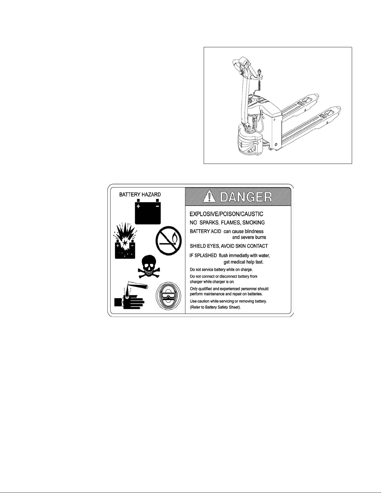
The model number will be found on the name plate
(Figure 1-1) along with the serial number, lifting capacity, and load center. Figure 1-2 shows the locations of
the truck’s main components and controls.
BL-GL33-0618 - 09-12-2019 1-1
Figure 1-1 Name Plate
Page 6
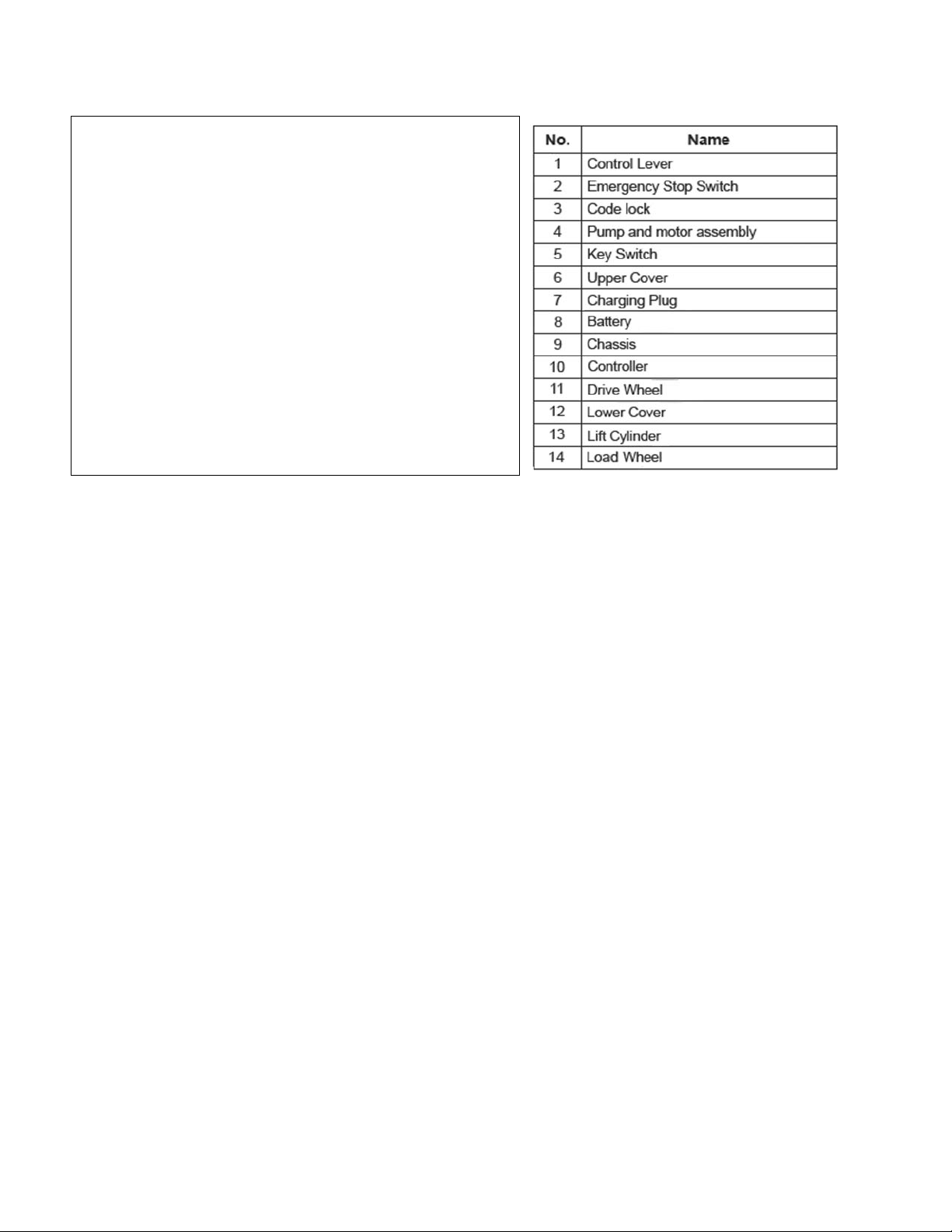
Figure 1-2 Lift Truck
GL33-14
1-3. SAFETY FEATURES.
The 988993 is designed and engineered to provide
maximum safety for operator and payload. Some of
the safety features incorporated into the design are:
• Dead-man brake to apply the brake and cut off drive
power when the steering arm is released.
• Belly-button switch to reverse truck should the operator accidentally pin himself against a wall or
obstruction when backing up in slow speed.
• All control functions automatically return to “OFF”
when released.
• Emergency Disconnect within operator's reach.
• Readily accessible horn button.
• Handle to provide a firm hand hold for operator.
• Flow control valve regulates maximum lowering
speed within prescribed limits.
• Relief valve maintains hydraulic pressure within prescribed limits.
• High visibility color scheme of truck provides visual
alert of truck’s presence.
• Battery Indicator
1-2 BL-GL33-0618 - 09-12-2019
Page 7

SECTION 2
OPERATION
2-1. GENERAL.
This section gives detailed operating instructions for
the 988993 lift truck. The instructions are divided into
the various phases of operations, such as operating
lift, driving, and stopping. Routine precautions are
included for safe operation.
2-2. OPERATING PRECAUTIONS.
WARNING: Improper operation of the lift truck may
result in operator injury, or load and/or lift
truck damage. Observe the following
precautions when operating the 988993
lift truck.
The following safety precautions must be adhered to
at all times.
• Do not operate this truck unless you have been
trained and authorized to do so and have read all
warnings and instructions in this manual and on the
truck.
• All warnings and instructions must be read and
understood before using the equipment.
• Equipment must be inspected by a qualified person
on a regular basis.
• Do not operate this truck until you have checked its
condition. Give special attention to Wheels, Horn,
Batteries, Controller, Lift System, Brakes, Steering
Mechanism, Guards and Safety Devices
• Operate truck only from designated operation position. Wear foot protection. Do not carry passengers.
• Observe applicable traffic regulations. Yield right of
way to pedestrians. Slow down and sound horn at
cross aisles and wherever vision is obstructed.
• Start, stop, travel, steer and brake smoothly. Slow
down for turns and on uneven or slippery surfaces
that could cause truck to slide or overturn. Use special care when traveling without load as the risk of
overturn may be greater.
• Always look in direction of travel. Keep a clear view,
and when load interferes with visibility, travel with
load or lifting mechanism trailing.
• Do not overload truck. Check nameplate for load
weight and load center information.
• Before lifting, be sure load is centered, forks are
completely under load, and load is as far back as
possible against the chassis.
• Do not handle loads which are higher than the chassis unless load is secured so that no part of it could
fall backward.
• When leaving truck, neutralize travel control. Fully
lower lifting mechanism and set brake. When leaving
truck unattended, turn off key switch and disconnect
switch, and remove key.
2-3. BEFORE OPERATION
Table 2-1 covers important inspection points on the
988993 lift truck which should be checked prior to
operation. Depending on use, some trucks may
require additional checks.
Figure 2-1 shows a sample format for an Operator
Checklist, which can be modified as necessary to fit
your operation.
WARNING: Periodic maintenance of this truck by a
QUALIFIED TECHNICIAN is required.
CAUTION: A QUALIFIED SERVICE TECHNICIAN
should check the truck monthly for
proper lubrication, proper fluid levels,
brake operation, motor maintenance and
other areas specified in the SECTION 3.
WARNING: If the truck is found to be unsafe and in
need of repair, or contributes to an
unsafe condition, report it immediately to
the designated authority. Do not operate
it until it has been restored to a safe
operating condition. Do not make any
unauthorized repairs or adjustments. All
service must be performed by a qualified
maintenance technician.
BL-GL33-0618 - 07-16-2019 2-1
Page 8

Table 2-1 Operator Checks
ITEM PROCEDURE
Transmission
and hydraulic
systems.
Forks Check for cracks and damage.
Safety signs Check that warning labels,
Horn Check that horn sounds when
Steering Check for binding or looseness in
Travel controls Check that speed controls on
Check for signs of fluid leakage.
nameplate, etc., are in good
condition and legible.
operated.
steering arm when steering.
control head operate in all
speed ranges in forward and
reverse and that belly button
switch functions.
ITEM PROCEDURE
Wheels Check drive wheel for cracks or
damage. Move truck to check
load for freedom of rotation.
Hydraulic
controls
Brake Check that brake actuates when
Deadman/
Parking brake
Battery
disconnect
Battery charge Check the battery indicator.
Check operation of lift and lower
to their maximum positions.
steering arm is raised to upright
position, and when lowered to
horizontal position.
Check that steering arm raises to
upright position when released
and brake applies.
Check that battery can be
disconnected and reconnected. Check for connector
damage.
2-2 BL-GL33-0618 - 07-16-2019
Page 9

R8549
Figure 2-1 Sample of Operator Check List
BL-GL33-0618 - 07-16-2019 2-3
Page 10
2-4. GENERAL CONTROL OPERATION.
R6617
R6618
R8505
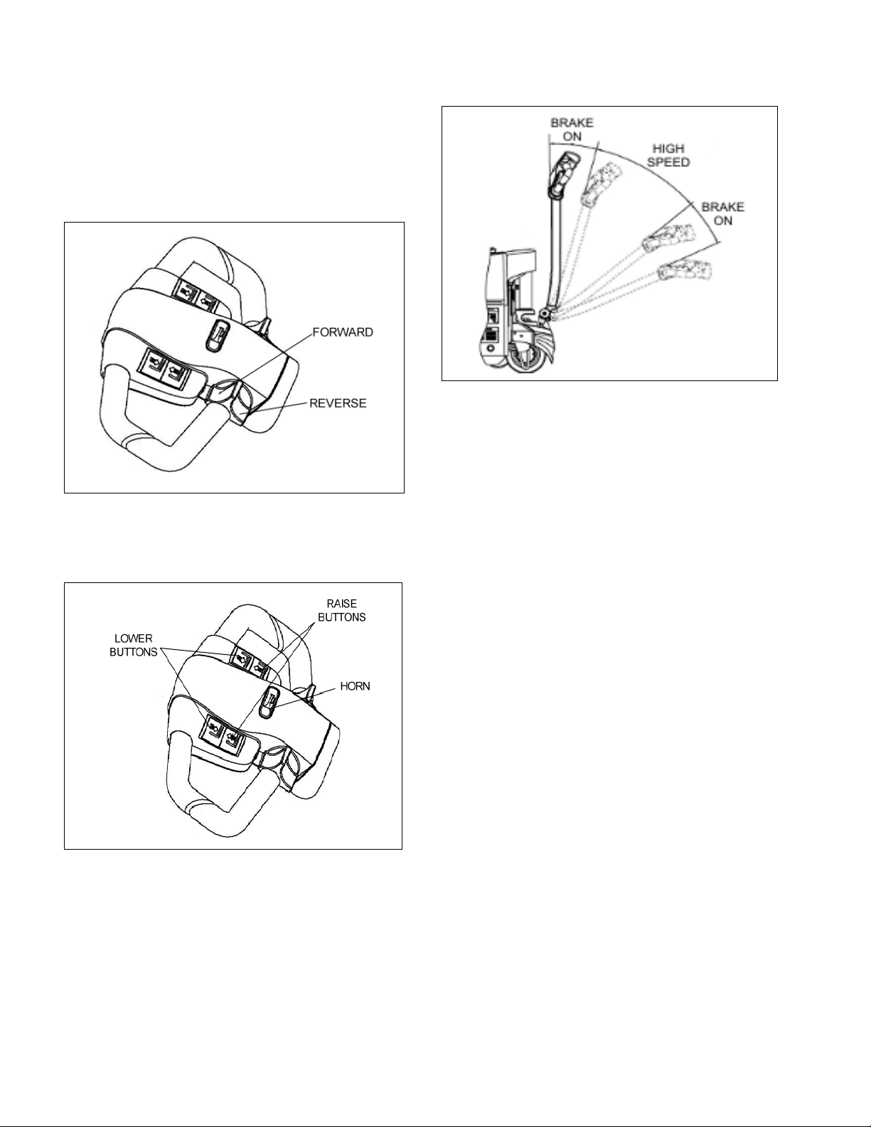
The speed control (See Figure 2-2) located on each
side of the control head provides fingertip control for
driving the truck. Rotate the control in the direction you
want to travel. The farther you rotate the control from
the neutral position, the faster the truck will travel.
Figure 2-2 Forward/Reverse Control
The pushbutton switches (See Figure 2-3), located on
the front of the control head activate the lift-lower controls and the horn.
Figure 2-4 Brake Actuation
2-5. DRIVING AND STOPPING PROCEDURES.
1. Turn on the emergency disconnect and the key
switch. Grasp the grips of the steering head so
that the speed control can be comfortably operated by either thumb.
2. Lower the steering arm to a comfortable position
above horizontal to disengage the brake and to
energize the electrical circuits. If the truck is not
moved, the electrical circuits will time out and will
deenergize. See Figure 2-4.
3. To move forward (with load in front), slowly press
the speed control forward. See Figure 2-2. Press
the forward speed control farther to increase
speed.
4. To slow down or stop, release the speed control
and lower or raise the steering arm to the horizontal or vertical position. See Figure 2-4. In those
positions, the brake engages, slowing or stopping
the truck.
5. Procedures for movement in reverse are the
same as in the forward direction except slowly
press the speed control backward. See Figure 2-
2.
Figure 2-3 Pushbutton Switches
The brake is fully applied by lowering or raising the
steering arm. (See Figure 2-4) All traction control
power is shut off when the brake is engaged. When
the steering arm is in the upright position, the brake
acts as a parking brake. Deadman braking occurs
when the handle is released and spring action raises
2-6. BELLY-BUTTON SWITCH.
The belly-button switch (Figure 2-5) minimizes the
possibility of the driver being pinned by the steering
arm while driving the lift truck in slow speed. If the
switch presses against the operator while the lift truck
is being driven toward the operator, the switch
changes the direction of the lift truck.
steering arm to the upright position.
2-4 BL-GL33-0618 - 07-16-2019
Page 11
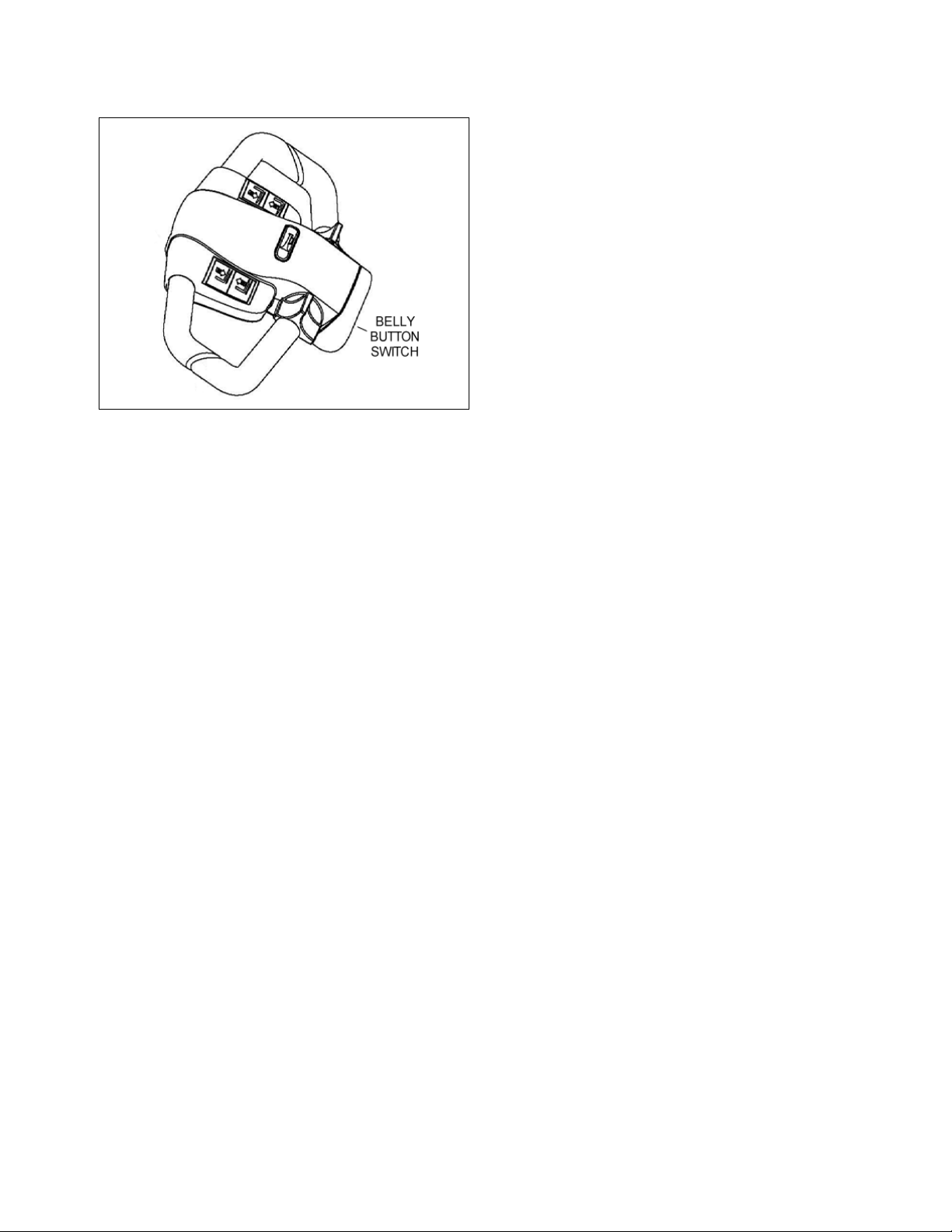
Figure 2-5 Belly-Button Switch
R6619
2-7. STEERING ARM GAS SPRING.
The steering arm gas spring automatically raises the
steering arm to the upright position when the steering
arm is released. If the steering arm does not return
fully, the steering arm gas spring requires replacement. Return truck to maintenance for repair.
2-8. LIFT AND LOWER CONTROLS.
Lift/Lower Control buttons are located on the steering
control head. (Figure 2-3)
To lift forks, push in either LIFT button and hold until
forks reach desired height. To lower forks, push in
either LOWER button and hold until forks descend to
desired height.
2-9. LOADING AND UNLOADING.
1. Move truck to location where load is to be picked
up.
2. Move the truck into position so forks are within
pallet or skid, and the load is centered over the
forks and as far back as possible.
3. Raise forks to lift load.
4. Drive to area where load is to be placed.
5. Move truck to align load with its new position.
6. Lower the load until it rests squarely in place and
the forks are free.
7. Slowly move the truck out from under the load.
2-10.PARKING.
When finished with moving loads, return the truck to its
maintenance or storage area. Turn off the emergency
Disconnect and the key switch. Charge batteries as
necessary. Refer to battery care instructions, SEC-
TION 3.
BL-GL33-0618 - 07-16-2019 2-5
Page 12

NOTES
2-6 BL-GL33-0618 - 07-16-2019
Page 13

SECTION 3
PLANNED MAINTENANCE
3-1. GENERAL.
Planned maintenance consists of periodic visual and
operational checks, parts inspection, lubrication, and
scheduled maintenance designed to prevent or discover malfunctions and defective parts. The operator
performs the checks in SECTION 3, and refers any
required servicing to a qualified maintenance technician who performs the scheduled maintenance and
any required servicing.
3-2. MONTHLY AND QUARTERLY CHECKS.
Table 3-1 is a monthly and quarterly inspection and
service chart based on normal usage of equipment
eight hours per day, five days per week. If the lift truck
is used in excess of forty hours per week, the frequency of inspection and service should be increased
accordingly. These procedures must be performed by
a qualified service technician or your Global Industrial
Service Representative.
3-3. BATTERY CARE.
3-3.1. General
The 988993 may be equipped with maintenance free
batteries.
The care and maintenance of the battery is very
important to obtain efficient truck operation and maximum battery life.
Table 3-1 Monthly and Quarterly Inspection and Service Chart
CAUTION: Gases produced by a battery can be
explosive. Do not smoke, use an open
flame, create an arc or sparks in the
vicinity of the battery. Ventilate an
enclosed area well when charging.
CAUTION: Batteries contain sulfuric acid which may
cause severe burns. Avoid contact with
eyes, skin or clothing. In case of contact,
flush immediately and thoroughly with
clean water. Obtain medical attention
when eyes are affected. A baking soda
solution (one pound to one gallon of
water) applied to spilled acid until bubbling stops, neutralizes the acid for safe
handing and disposal.
Leakage voltage from battery terminals to battery case
can cause misleading trouble symptoms with the truck
electrical system. Since components of the truck electrical system are insulated from truck frame, leakage
voltage will not normally affect truck operation unless a
short circuit or breakdown of circuit wire insulation to
truck frame occurs.
A voltage check from battery connector terminal to
battery case should indicate near zero volts. Typically,
however, the sum of the voltages at both terminals will
equal battery volts. This leakage voltage will discharge
the battery. As battery cleanliness deteriorates, the
usable charge of the battery decreases due to this self
discharge.
VISUAL CHECKS
INTERVAL INSPECTION OR SERVICE
Monthly Check electrical brake for proper operation.
Monthly Check load wheels for wear. A poly load wheel must be replaced if worn to within 1/16 inch
of hub. Check for separation from hub.
Monthly Check drive wheel for wear. A poly drive wheel must be replaced if worn to within 3/4 inch of
hub. Check for separation from hub.
Monthly Inspect wiring for loose connections and damaged insulation.
Monthly Inspect contactors for proper operation.
Monthly Check deadman brake switch for proper operation.
Quarterly Check lift cylinder for leakage.
Quarterly Check for excessive jerking of steering arm when stopping or starting.
BL-GL33-0618 - 09-12-2019 3-1
Page 14

Although a leakage voltage reading of zero volts may
not be possible, a cleaner battery will have more
usable charge for truck operation and not affect operation of electronic devices on the unit.
3-3.2. Safety Rules
• Wear protective clothing, such as rubber apron,
gloves, boots and goggles when performing any
maintenance on batteries. Do not allow electrolyte to
come in contact with eyes, skin, clothing or floor. If
electrolyte comes in contact with eyes, flush immediately and thoroughly with clean water. Obtain medical attention immediately. Should electrolyte be
spilled on skin, rinse promptly with clean water and
wash with soap. A baking soda solution (one pound
to one gallon of water) will neutralize acid spilled on
clothing, floor or any other surface. Apply solution
until bubbing stops and rinse with clean water.
• If truck is equipped with wet cell batteries, keep vent
plugs firmly in place at all times except when adding
water or taking hydrometer readings. Do not allow
dirt, cleaning solution or other foreign material to
enter cells. Impurities in electrolyte has a neutralizing effect reducing available charge.
• Do not bring any type of flame, spark, etc., near the
battery. Gas formed while the battery is charging, is
highly explosive. This gas remains in cell long after
charging has stopped.
• Do not lay metallic or conductive objects on battery.
Arcing will result.
• Do not touch non-insulated parts of DC output connector or battery terminals to avoid possible electrical shock.
• De-energize all AC and DC power connections
before servicing battery.
• Do not charge a frozen battery.
• Do not use charger if it has been dropped or otherwise damaged.
3-3.3. Battery Care and Charging
CAUTION: Never smoke or bring open flame near
the battery. Gas formed during charging
is highly explosive and can cause serious injury.
1. Charge the battery only in areas designated for
that use.
2. Battery terminals should be checked and cleaned
of corrosion regularly. Good battery terminal contact is essential not only for operation, but also for
proper charging of the battery.
3. The charging requirements will vary depending on
the use of the truck. The battery should be given
as equalizing charge on a weekly basis. This
charge should normally be an additional three
hours at the finish rate.
4. Make certain battery used meets weight and size
requirements of truck. NEVER operate truck with
an undersized battery.
3-3.4. Battery Cleaning
Always keep vent plugs tightly in place when cleaning
battery. When properly watered and charged, the battery will remain clean and dry. All that is necessary is
to brush or blow off any dust or dirt that may accumulate on them. However, if electrolyte is spilled or overflows from a cell, it should be neutralized with a
solution of baking soda and water, brushing the soda
solution beneath the connectors and removing grime
from the covers. Then rinse the battery with cool water
from a low pressure supply to remove the soda and
loosen dirt. If batteries stay wet consistently, they may
be either overcharged or over filled. This condition
should be investigated and corrected.
3-3.5. MAINTENANCE FREE BATTERIES
Some trucks may be equipped with maintenance free
batteries. These batteries are completely sealed, will
not require any watering and have a full 80% discharge available.
Sealed Maintenance Free batteries contain a pressure
release valve and under normal operating conditions
do not require any special ventilation.
CAUTION: Do not try to open this battery or remove
the pressure release valve.
Only under severe overcharging, such as connected
to an improperly sized charger, will any significant
amount of gasses be released from the battery. Also,
being a valve regulated battery, it never requires
watering.
3-2 BL-GL33-0618 - 09-12-2019
Page 15
3-4. CHARGING BATTERIES
GL33-16
R6115
Charging requirements will vary depending on depth of
discharge and temperature. Follow safety rules when
placing a battery on charge.
Proceed as follows:
1. Park truck at charging station with forks lowered
and turn the key switch off.
2. Check the condition of the AC cord and battery
cables. If there are any cuts in the cable, any
exposed wires, loose plugs or connectors, DO
NOT attempt to charge the batteries. Contact
appropriate personnel for repairs to be made.
3. Pull the charger cord out of the top cover (Figure
3-1) and connect to the appropriate power supply.
Figure 3-1 Battery Charging
BL-GL33-0618 - 09-12-2019 3-3
Page 16
3-5. BATTERY REPLACEMENT
GL33-17
R6761
R6762
Access to the batteries requires removing the cover.
Charging requirements will vary depending on depth of
discharge and temperature. Follow safety rules when
placing a battery on charge.
Proceed as follows:
a. Remove top cover screws (1, Figure 3-2) and
remove the upper compartment cover (2).
Figure 3-2 Cover Removal
b. Remove four and front cover, this will expose
the 2 batteries. (Figure 3-3).
P
Figure 3-4 Disconnect Battery Cables
e. Install in the reverse order of remove.
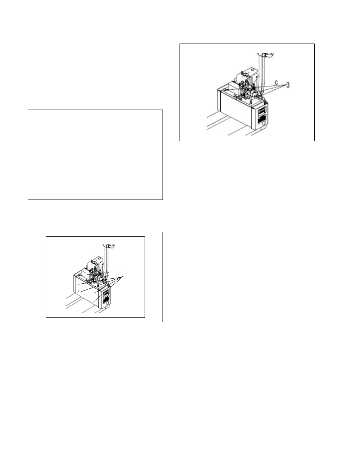
Figure 3-3 Screw Removal
c. Tag and disconnect the three battery cables
(Figure 3-4).
d. To remove the batteries pull each one out
individually as required.
3-4 BL-GL33-0618 - 09-12-2019
Page 17

3-6. LUBRICATION.
Refer to Table 3-2 for the recommended types of
grease and oil. Table 3-3 in conjunction with Figure 3-5
identifies the items requiring lubrication.
Table 3-2 Recommended Lubricants
(See Table 3-3 for Application)
No. 1 Grease—Lithium base, general purpose
No. 2 (Note) Grease—Lithium base
No. 3 Hydraulic oil-Heavy duty with a viscosity of
150 SUS foam suppressing agent and
rust and oxidation inhibitors
Hydraulic oil-Heavy duty with a viscosity of
100 SUS foam suppressing agent and
rust and oxidation inhibitors (Note)
No. 4 SAE 30 or 40 Engine lubricating oil
BL-GL33-0618 - 09-12-2019 3-5
Page 18

Figure 3-5 Lubrication Diagram
GL33-18
Table 3-3 Lubrication Chart
FIG 3-2
INDEX
NO.
LOCATION METHOD OF
APPLICATION
TYPE
(Table
3-3)
1 Transmission Grease Can No. 1 Fill to level plug
2 Hydraulic Reservoir
Capacity-1 quarts
Can No. 3 With lift carriage fully lowered, fill
reservoir with hydraulic oil to 1
inch below opening
3 Lift Linkage Fittings* Gun No. 2 Pressure lubricate.
* Raise lift carriage to gain access to grease fittings.
APPLICATION
OF
LUBRICANT
3-6 BL-GL33-0618 - 09-12-2019
Page 19

SECTION 4
TROUBLESHOOTING
4-1. GENERAL
Use Table 4-1 and Figure 4-3 as a guide to determine
possible causes of trouble. The table is divided into
five main categories: Truck and Hydraulic System Will
Table 4-1 Troubleshooting Chart
MALFUNCTION PROBABLE CAUSE CORRECTIVE ACTION
TRUCK AND HYDRAULIC
SYSTEM WILL NOT OPERATE
Truck will not travel nor will lift sys-
tem operate.
TRUCK DOES NOT OPERATE
FORWARD OR REVERSE
Truck does not travel forward or
reverse. All other functions
operate normally.
Truck travels forward but not in
reverse.
Truck travels reverse but not in
forward.
Truck travels forward and in
reverse at lower speeds; will
not travel at high speed.
TROUBLE WITH BRAKING
Truck does not slow with brake, or
brake does not engage.
a. Fuse blown. Check fuse and replace if
b. Battery dead or disconnected. Check battery connections and
c. Keyswitch defective. Bypass keyswitch to determine if it
d. Defective wiring. Check for open circuit. Repair as
a. Check all wiring. A loose con-
nection may be the cause of
malfunction.
b. Defective deadman switch. Check and replace switch if
c. Defective controller. Check for proper operation and
d. Defective potentiometer. Check and replace potentiometer
Defective potentiometer in control
head.
Defective potentiometer in control
head.
Defective potentiometer in control
head.
a. Defective deadman switch. Check deadman switch for
b. Defective electric brake. Replace brake.
Not Operate: Truck Does Not Operate Forward or
Reverse: Trouble With Braking: Trouble With Lifting Or
Lowering, and Miscellaneous malfunctions.
necessary.
check battery voltage.
is malfunctioning.
required.
Tighten all loose connections
before further troubleshooting.
defective.
replace if necessary.
if defective.
Check and replace potentiometer
if defective.
Check and replace potentiometer
if defective.
Check and replace potentiometer
if defective.
continuity. If none found when
the control arm is in the brake
position, replace switch.
Brake will not release. a. Brake temperature above
281F (140C).
b. Open brake circuitry or wiring. Make voltage checks.
BL-GL33-0618 - 09-12-2019 4-1
Allow to cool.
Page 20

Table 4-1 Troubleshooting Chart - Continued
MALFUNCTION PROBABLE CAUSE CORRECTIVE ACTION
TROUBLE WITH BRAKING -
Continued
Brake drags. Defective electric brake. Replace.
Brake grabs. Defective electric brake. Replace.
Abnormal noise and chatter when
brake is applied.
TROUBLE WITH LIFTING OR
LOWERING
Oil sprays or flows from the top of
the lift cylinder.
Squealing sounds when lifting
forks.
Forks do not lift to top. Oil level too low. Add oil to reservoir.
Weak, slow or uneven action of
hydraulic system.
Forks do not lift, pump motor does
not run.
Forks do not lift, motor runs. Defect in hydraulic system. Check the oil level in the reservoir
Defective electric brake. Replace.
.
Defective packing in lift cylinder Repair lift cylinder.
a. Oil level too low. Identify oil leak.
b. Lift linkage binding. Apply grease.
a. Defective pump or relief valve. Check pressure. Adjust as
necessary.
b. Worn lift cylinder. Replace cylinder.
c. Load larger than capacity. Refer to I.D.plate for capacity.
d. Defective lift motor solenoid. Replace solenoid on electrical
panel.
e. Battery charge low. Charge battery.
a. Battery is dead or discon-
nected.
b. Defective wiring. Check and repair as required.
c. Defect in electrical system for
operating pump motor.
Check and recharge if required.
Check lift switch in control head,
as well as the solenoid.
and the oil lines to the lift cylinder, and repair as required. If
normal, check the hydraulic
pump, and relief valve. Repair,
or adjust.
4-2 BL-GL33-0618 - 09-12-2019
Page 21

Table 4-1 Troubleshooting Chart - Continued
MALFUNCTION PROBABLE CAUSE CORRECTIVE ACTION
TROUBLE WITH LIFTING OR
LOWERING - Continued
Forks lift, but will not go down. Defect in hydraulic system Check lowering control switch in
control head and lowering solenoid on valve assembly.
Replace as required.
Load will not hold a. Oil bypassing internally in con-
trol valve
b. Worn lift cylinder or packing. Repack cylinder.
Platform does not lift to top. Pump
motor runs.
Forks creep downward under load
when in a raised position.
MISCELLANEOUS
Steering arm does not return to
the upright position.
Truck moves forward when arm is
pulled down.
Steering arm jerks excessively
starting or stopping the truck.
Drive motor is jerky. Motor internally damaged or worn. Replace motor.
a. Oil level too low. Add oil to reservoir.
b. Load larger than capacity. Refer to nameplate on side of
c. Batteries need charging. Change batteries.
Leak in hydraulic system, lift cylin-
der or lowering valve.
a. Week return spring. Replace spring.
b. Binding. Check and free the binding item.
a. Belly-button switch defective. Check for short, and repair or
b. Short in control head. Check wiring and repair as
Drive wheel worn. Replace drive wheel if worn to
Replace valve assembly.
mast for maximum load capacity.
Check for leaking fitting in hydrau-
lic line and repair as required.
Repack lift cylinder or replace
valve assembly.
Verify that the cable has not
been damaged. Repair or
replace as needed.
replace as necessary.
required.
within 3/4 inch of hub.
BL-GL33-0618 - 09-12-2019 4-3
Page 22

4-2. CONTROLLER TROUBLESHOOTING
R6759
R7090
4-2.1. Fault Detection.
The controller provides diagnostics information to
assist technicians in troubleshooting drive system
problems. When a fault is detected, the appropriate
fault code is signaled via the panel mounted LED.
4-2.2. Hand Held Programmer (Optional)
The hand held programmer is available that is
designed specifically for use with the controller. The
programmer is available through your Global Industrial
dealer.
4-2.3. Fault Recording.
Fault events are recorded in the controller's memory.
However, multiple occurrences of the same fault are
recorded as one occurrence.
The fault event list can be loaded into the programmer
for readout. The Special Diagnostics mode provides
access to the controller's diagnostic history file. The
history file contains the entire fault event list created
since the diagnostic history file was last cleared. The
standard Diagnostics mode provides information about
only the currently active faults.
1. Disconnect the battery charger and connect the
programmer to the 4-pin connector (Figure 4-1)
on the controller.
Figure 4-1. Controller Terminals
2. Turn the lift truck key switch to the ON position.
The programmer should “power up” with an initial
display (2, Figure 4-2), and the controllers Status
LED should begin steadily blinking a single flash.
If neither happens, check for continuity in the key
switch circuit and controller ground.
4-2.4. General Checkout.
Carefully complete the following checkout procedure.
If you find a problem during the checkout, refer to
paragraph 4-2.7. for further information.
The checkout can be conducted with or without the
handheld programmer (See Paragraph 4-2.2.). However, the checkout procedure is easier with a programmer. To evaluate the system without a programmer,
observe the LED and note the flashing pattern and
refer to for the code description.
CAUTION: Put the vehicle up on blocks to get the
drive wheel off the ground before beginning these tests.
Turn the keyswitch off and make sure the
brake is applied, the throttle is in neutral,
and the forward/reverse switches are
open.
Do not stand, or allow anyone else to
stand directly in front of or behind the
vehicle during the tests.
Figure 4-2. Hand Held Programmer
4-4 BL-GL33-0618 - 09-12-2019
Page 23

3. Put the controller into the diagnostic mode by
pressing the “Menu Navigation Key” (1, Figure 4-
2). Using the Navigation key, select the Faults
menu. Display the Faults menu by pressing the
Right side of the Navigation key. Press the Right
side of the Navigation key again to display the list
of System Faults. The display should indicate “No
Known Faults.”
Release the brake by pulling down the steering
arm into the operating position. The controllers
LED should continue blinking a single flash and
the programmer should continue to indicate no
faults. If there is a problem, the LED will flash a
diagnostic code and the programmer will display a
diagnostic message. If you are conducting the
checkout without a programmer, look up the LED
diagnostic code in Table 4-3.
When the problem has been corrected, it may be
necessary to cycle the brake in order to clear the
fault code.
4. With the brake released, select a direction and
operate the throttle. The motor should begin to
turn in the selected direction. If it does not, verify
the wiring to the forward/reverse switches and
motor. The motor should run proportionally faster
with increasing throttle. If not, refer to Paragraph
4-2.7.
5. Put the controller into the test mode by using the
Navigation key (1) to select the "Monitor" menu.
Select the Monitor mode by pressing the "Right"
arrow on the Navigation key. Press the Navigation
key "Down" arrow to scroll down to observe the
status of the forward, reverse, brake, emergency
reverse, and mode switches. Cycle each switch in
turn, observing the programmer. Each input
should show the correct state on the programmer.
6. Check the controller's fault detection circuitry as
described in Paragraph 4-2.5.
7. Take the vehicle off the blocks and drive it in a
clear area. It should have smooth acceleration
and good top speed.
8. Test the plug braking of the vehicle. The vehicle
should smoothly slow to a stop and reverse direction, with the audible plugging tone.
9. Verify that all options, such as high pedal disable
(HPD), static return to off (SRO), and anti-tiedown, are as desired.
10. Check to see whether the emergency reverse
(belly button) feature is working correctly. Verify
that the circuit is operational by momentarily disconnecting one of the emergency reverse wires.
The vehicle should be disabled and a fault indicated.
BL-GL33-0618 - 09-12-2019 4-5
Page 24

4-2.5. Diagnostic History
The handheld programmer can be used to access the
controller's diagnostic history file. When the programmer is connected to the unit, the error log file is automatically uploaded into the handheld programmer.
To see the present status of the unit, use the Menu
Navigation Key (1, Figure 4-2) to select:
Faults->System Faults.
To access this log, use the Menu Navigation Key to
select:
Faults->Fault History
The faults are shown as a code and descriptive text. If
there are multiple faults, you have to scroll through the
list using the Up and Down Buttons on the Menu Navigation Key
The faults may be intermittent faults, faults caused by
loose wires, or faults caused by operator errors. Faults
such as HPD or over-temperature may be caused by
operator habits or by overloading.
After a problem has been diagnosed and corrected,
clearing the diagnostic history file is recommended.
This allows the controller to accumulate a new file of
faults. By checking the new diagnostic history file at a
later date, you can quickly determine whether the
problem has been completely fixed.
To clear the diagnostic history file, select:
Faults->Clear Fault History.
You will be asked to confirm your actions. Use the
"plus" arrow (+) for yes to clear the menu and the
"minus" arrow (-) (3) to cancel your selection and not
clear the Fault History.
4-2.6. Test the Fault Detection Circuitry
1. Put the vehicle up on blocks to get the drive wheel
off the ground.
1. Turn off the key switch and emergency disconnect.
2. Using an inline fuse holder fitted with a 10 amp
fuse and alligator clips, connect the controller's M
and B- terminals.
3. Turn on the emergency disconnect (17) the key
switch (20). Release the brake and apply the
throttle. The motor should not operate.
4. Leave the key switch on and remove the in-line
fuse wire. The vehicle status should continue to
remain off.
5. Cycle the key switch off and on. Release the
brake and apply the throttle. The vehicle should
now operate normally.
4-2.7. Diagnostics and Troubleshooting.
The motor controller provides diagnostics information
to assist in troubleshooting drive system problems.
The diagnostics information can be obtained in two
ways:
• Reading the appropriate display on the programmer
• Observing the fault codes issued by the panel
mounted Status LED.
4-2.7.1. LED Diagnostics
During normal operation with no faults present, the
Status LED is steady on. If the controller detects a fault
the Status LED flashes a fault identification code continuously until the fault is corrected.
NOTE: The Status LED can only indicate one fault at
a time. If multiple faults are detected, the
highest priority fault code flashes until it is
cleared.
With Fault Code Type parameter is set to 0, the status
LED uses the fault codes listed in . Six single-digit
codes are used: 2, 3, 5, 6, 7, and 9.
For suggestions about possible causes of the various
faults, refer to Table 4-3 Troubleshooting Chart.
4-6 BL-GL33-0618 - 09-12-2019
Page 25

Table 4-2 Programmable Parameters
Parameter Factory Setting Description
DRIVE MENU
Accel Max Speed 1.5 sec.
Accel Min Speed 5.0 sec.
Decel High Speed 0.6 sec.
Decel Low Speed 1.5 sec.
90A
Sets the rate (in seconds) at which the speed command
increases when throttle is applied with the speed limit pot is
in its maximum speed position, and the vehicle is traveling
forward. Larger values represent slower response.
Note: Allowable range is restricted by the Accel Min Speed set-
ting.
Sets the rate (in seconds) at which the speed command
increases when throttle is applied while the speed limit pot is
in its minimum speed position, and the vehicle is traveling
forward. Larger values represent slower response
Note: Allowable range is restricted by the Accel Max Speed
setting.
Sets the rate (in seconds) that is used to slow down the vehicle
when it is traveling forward at high speed and throttle is
reduced. Larger values represent slower response.
Note: Allowable range is restricted by the Decel Low Speed
setting.
Sets the rate (in seconds) that is used to slow down the vehicle
when it s traveling forward at low speed and throttle is
reduced. Larger values represent slower response.
Rev Accel Max Speed 1.5sec.
Rev Accel Min Speed 5.0 sec.
Rev Decel High Speed 0.5 sec.
Note: Allowable range is restricted by the Decel High Speed
setting.
Sets the rate (in seconds) at which the speed command
increases when throttle is applied while the speed limit pot is
in its maximum speed position, and the vehicle is traveling in
reverse. Larger values represent slower response.
Note: Allowable range is restricted by Rev Accel Min Speed
setting.
Sets the rate (in seconds) at which the speed command
increases when throttle is applied while the speed limit pot is
in its minimum speed position, and the vehicle is traveling in
reverse. Larger values represent slower response.
Note: Allowable range is restricted by Rev Accel Max Speed
setting.
Sets the rate (in seconds) that is used to slow down the vehicle
when it is traveling in reverse at high speed and throttle is
reduced. Larger values represent slower response.
Note: Allowable range is restricted by Rev Decel Low Speed
setting.
BL-GL33-0618 - 09-12-2019 4-7
Page 26

Table 4-2 Programmable Parameters - Continued
Parameter Factory Setting Description
DRIVE MENU Cont.
Rev Decel Low Speed 1.5 sec.
Key Off Decel 0.7 sec.
E Stop Decel 0.6 sec.
E Stop Pause 0.5 sec.
Soft Start 25%
Gear Soften 15%
Creep Speed 7%
Push Max Speed N/A
90A
Sets the rate (in seconds) that is used to slow down the vehicle
when it is traveling in reverse at low speed and throttle is
reduced. Larger values represent slower response.
Note: Allowable range is restricted by Rev Decel High Speed
setting.
Sets the rate (in seconds) that is used to slow down the vehicle
at key-off or in the event of a major fault.
Sets the rate (in seconds) that is used to slow down the vehicle
during emergency reverse, i.e., when a throttle command
>80% in the reverse direction is given while the vehicle is
moving forward. This gives the operator a way to stop more
quickly when unexpected conditions arise.
Sets a pause before reversing direction after an emergency
reverse stop. This gives the operator time to return the throttle to neutral without moving backwards
This parameter can be used to soften the bump associated
with gear slack in the transaxle when throttle is applied from
the neutral state. Larger values provide a softer slack takeup.
This parameter is intended to soften the bump associated with
gear slack in the transaxle when throttle is released and then
reapplied while the vehicle is still moving. Larger values provide a softer slack take-up.
Creep Speed helps to prevent vehicle rollback on inclines
when the brake is released with very little throttle applied. It is
activated when the throttle request exceeds the throttle deadband threshold.
Sets the maximum speed at which the vehicle can be pushed.
When the vehicle is powered on and in neutral, it enters the
push mode when the push button is activated. The electromagnetic brake is released, driving is inhibited, and speed is
limited to Push Max Speed. When the vehicle is not powered
on and the brake is mechanically released to enable pushing,
Push Max Speed still applies. Once sufficient voltage is generated by the motor, speed will be limited by the controller
Sets the speed at which a gentler deceleration is initiated when
the throttle is released to neutral; larger values start the soft
stop deceleration sooner.
Soft Stop Speed 13%
4-8 BL-GL33-0618 - 09-12-2019
Page 27

Table 4-2 Programmable Parameters - Continued
Parameter Factory Setting Description
SPEED MENU
Max Speed
Mode 1
Mode 2
Min Speed
Mode 1
Mode 2
Rev Max Speed
Mode 1
Mode 2
90A
100%
30%
20%
20%
100%
30%
During forward operation, defines the requested speed at full
throttle when the speed limit pot is in its maximum speed
position.
Note: Allowable range is restricted by the M1/M2 Min Speed
setting.
During forward operation, defines the requested speed com-
mand at full throttle when the speed limit pot is in its minimum
speed position. Min Speed cannot be set higher than the programmed Max Speed.
Note: Allowable range is restricted by the M1/M2 Max Speed
setting.
Note: For this parameter to apply, a speed limit pot must be
installed in parallel with the throttle and the Speed Limit Pot
parameter must be programmed On (see Throttle menu).
During reverse operation, defines the requested speed at full
throttle when he speed limit pot is in its maximum speed position.
Note: Allowable range is restricted by M1/M2 Rev Min Speed
setting.
During reverse operation, defines the requested speed com-
mand at full throttle when the speed limit pot is in its minimum
speed position. Rev Min Speed cannot be set higher than the
programmed Rev Max Speed.
Note: Allowable range is restricted by M1/M2 Rev Max Speed
setting.
Note: For this parameter to apply, a speed limit pot must be
Rev Min Speed
Mode 1
Mode 2
BL-GL33-0618 - 09-12-2019 4-9
10%
10%
installed in parallel with the throttle and the Speed Limit Pot
parameter must be programmed On (see Throttle menu).
Page 28

Table 4-2 Programmable Parameters - Continued
Parameter Factory Setting Description
THROTTLE MENU
Type 7
PotHigh 5V
PotLow 0V
Neutral Deadband 5%
Throttle Max 90%
HPD ON
90A
The 1212 controller can accept inputs from both 5k, 3-wire
pot throttles and voltage throttles. Set the throttle type parameter to match the throttle used in your application.
5k, 3-wire pot throttles
0 = wigwag
1 = inverted wigwag
2 = single-ended; neutral when wiper at PotLow
3 = inverted single-ended; neutral when wiper at PotHigh
4 = unipolar.
Voltage throttles
5 = wigwag
6 = inverted wigwag
7 = single-ended; neutral when wiper PotLow
8 = inverted single-ended voltage; neutral when wiper
PotHigh
9 = unipolar
Sets the maximum voltage for voltage throttles (Types 5–9).
For 5k, 3-wire pot throttles, PotHigh is determined by the
throttle itself.)
Sets the maximum voltage for voltage throttles (Types 5–9).
For 5k, 3-wire pot throttles, PotLow is determined by the
throttle itself.)
Sets the throttle range the controller interprets as neutral.
Increasing the parameter setting increases the neutral range.
This parameter allows the neutral deadband to be defined
wide enough to ensure the controller goes into neutral when
the throttle is released.
Sets the pot wiper voltage required to produce 100% controller
output. Increasing the Throttle Max setting reduces the wiper
voltage required, and therefore reduces the stroke necessary
to produce full output. This feature allows reduced-range
throttle assemblies to be used.
When programmed On, vehicle drive is inhibited if a throttle
command outside the neutral deadband is issued before the
controller is powered up. Drive will continue to be inhibited
until the throttle is returned to within the neutral deadband. If
the HPD fault is not cleared within 10 seconds, a wiring fault
is declared and a power cycle is required.
This parameter is used to enable/disable the speed limit pot. If
no speed limit pot is used, set Speed Limit Pot to Off.
Speed Limit Pot OFF
4-10 BL-GL33-0618 - 09-12-2019
Page 29

Table 4-2 Programmable Parameters - Continued
Parameter Factory Setting Description
THROTTLE MENU Continued
90A
The throttle map parameter adjusts the static throttle map. The
parameter setting corresponds to the throttle command at
half throttle.
Throttle Map 50%
Tremor Suppression 50%
Calibration OFF
CURRENT MENU
Main Current Limit 90A
Braking Current Limit 90A
Boost Current 90A
A setting of 50% provides linear response. Values below 50%
reduce the throttle command at low throttle positions, providing enhanced slow speed maneuverability. Values above
50% give the vehicle a faster, more responsive feel at low
throttle positions.
This parameter can be used to limit the controller’s response
to sharp throttle movements, such as movements resulting
from hand tremors.
Larger values will provide a steadier ride, but they also result in
more sluggish response to throttle request. There is thus a
trade-off between crispness of response (low Tremor Suppression settings) and steady speed in the presence of tremors (high settings).
Wigwag and unipolar throttle pots should be centered. Setting
this parameter to On inhibits driving and puts the controller
into throttle autocalibration mode.
Setting the parameter Off returns the controller to normal oper-
ation.
Sets the maximum current the controller will supply to the
motor during normal driving. By limiting the current supplied,
this parameter can be used to protect the motor from potentially damaging currents or to reduce the maximum torque
applied to the drive system.
Sets the maximum current the controller will supply to the
motor during braking. By limiting the current supplied, this
parameter can be used to protect the motor from potentially
damaging currents or to reduce the maximum braking torque
applied to the drive system.
Boost current gives a brief boost of current that greatly
improves performance with transient loads, such as starting
on a hill, crossing a threshold, climbing obstacles, etc. When
the controller recognizes that the motor needs more current
to respond to a drive request, it provides a current boost of a
set amount for a set time.
The Boost Current parameter defines the motor current limit
the boost period
d.
Boost Time 0.0 sec.
during
This parameter sets the maximum time that the boost current is
allowe
BL-GL33-0618 - 09-12-2019 4-11
Page 30

Table 4-2 Programmable Parameters - Continued
Parameter Factory Setting Description
INHIBIT MENU
Type 2
Speed 0%
BRAKE MENU
Delay 0.3 sec
Fault Check ON Enables/disables the fault detection on the EM brake.
Hold Voltage 18V
Brake Light OFF
HORN MENU
Fault Beep N/A
Reverse Beep ON
Beep Constant OFF
90A
The flexible speed input at J1 Pin 6 can be used to limit or to
inhibit speed under certain conditions. For example, a switch
could be installed under the seat so that if the operator drives
the scooter while they are standing the max speed will be limited.
The Inhibit Type parameter is used to select how the inhibit
function will be implemented. Depending on how the inhibit
switch is wired into the system, set this parameter to:
0 = B- active
1 = B+ active
2 = Open circuit active
3 = B- inactive
4 = B+ inactive
5 = Open circuit inactive.
This parameter limits the maximum speed allowed during
speed inhibit mode. A setting of 0 prevents drive during
inhibit mode.
Sets the length of delay between when zero speed is com-
manded and the electromagnetic brake is engaged.
A high initial voltage is applied to the brake coil when the brake
is first released. After approximately 1 second, this peak voltage drops to the programmed Hold Voltage. The parameter
should be set high enough to hold the brake released under
all the shock and vibration conditions the vehicle will be subjected to.
When set to On, the horn output (J1 Pin 3) will act as a brake
light driver. The brake light must be driven by a relay. The
brake light will be turned on when the throttle is returned to
neutral and will remain on for about 2 seconds after the EM
brake is engaged.
When programmed On, the horn will be used to provide audi-
ble fault codes whenever faults are present. These are the
same fault codes that are flashed by the status LED. If a fault
should occur while the vehicle is driving in reverse with the
reverse beep active, the fault signal will take precedence. If
this audible fault alarm is not wanted, set Fault Beep to Off.
When programmed On, the horn will sound whenever the vehi-
cle is being driven in reverse. On vehicles with reverse
switches, the horn will sound when the reverse switch is activated.
Sets the reverse beep to be a constant tone (when pro-
grammed On) or a 1Hz pulse (when programmed Off).
4-12 BL-GL33-0618 - 09-12-2019
Page 31

Table 4-2 Programmable Parameters - Continued
Parameter Factory Setting Description
MOTOR MENU
System Resistance
Resistance Auto Comp ON
Auto Comp Current
Limit
Speed Scaler 27V
Current Rating 25A
Max Current Time 120 sec.
Cutback Gain 0%
BDI MENU
Full Voltage 24.4V
Empty Voltage 20.8V
90A
80 mΩ
73 mΩ
20%
Sets the system resistance (motor + brushes + wiring + con-
nections) used for load compensation and speed estimation.
Control system performance depends on this parameter
being set correctly; it must be set to the actual cold motor
resistance.
Resistance is automatically measured under a preset low cur-
rent before the brake is released. The measured motor resistance plays an important role in IR compensation.
The Resistance Auto Comp parameter enables/disables this
automatic function.
Sets the current limit used for automatic resistance testing, as
a percentage of the Main Current Limit (see Current menu).
The Speed Scaler parameter sets the maximum voltage that
can be applied to the motor. It can be used to eliminate variations in maximum speed that would otherwise result when
driving with a fully charged battery vs. a partially discharged
battery. If Speed Scaler is set to 23 volts, for example, the
maximum vehicle speed will be the same whether the actual
battery voltage is 27 volts or 23 volts or any value in between.
This parameter should be set to the current rating provided by
the motor 0–70 A manufacturer.
Sets the maximum amount of time the motor is allowed to run
at the main current limit.
When the motor overheats, the drive current is cut back until it
reaches the programmed Current Rating. The Cutback Gain
determines how quickly this cutback will occur, once the programmed Max Current Time has expired.
Voltage when the battery is fully charged. Note: Allowable
range is restricted by the Empty Voltage, Start Charge Voltage, and Reset Voltage settings.
Voltage when the battery is fully discharged.
Note: Allowable range is restricted by the Full Voltage setting.
Voltage, when a charger is connected, above which the battery
is considered finished charging.
Note: Allowable range is restricted by the Start Charge setting.
Full Charge Voltage 28.2V
BL-GL33-0618 - 09-12-2019 4-13
Page 32

Table 4-2 Programmable Parameters - Continued
Parameter Factory Setting Description
BDI MENU - Cont. 90A
Voltage above which the battery is considered to start
Start Charger
Voltage
Reset Voltage 25.0V
25.2V
charging.
Note: Allowable range is restricted by the Full Voltage and Full
Charge Voltage settings.
Voltage at which the BDI calculator will be reset to 100%, after
the charger is disconnected and the controller is powered up.
Note: Allowable range is restricted by the Full Voltage setting.
Discharge Factor 2.0
Charge Factor 2.0
Low BDI Level 40%
Low BDI Max Speed 15%
COMPENSATION MENU
IR Comp 70%
Discharge rate of the battery. Larger values are for larger bat-
teries, which discharge more slowly.
Charge rate of the battery. Larger values are for larger batter-
ies, which charge more slowly.
Sets the battery charge level at which maximum vehicle speed
will be limited in order to protect the battery from deep discharge. Setting Low BDI Level to zero disables this function
and allows the battery to discharge completely.
Sets the maximum allowed vehicle speed when the battery
charge falls below the programmed Low BDI Level.
Sets the motor load compensation. Higher values provide
stronger disturbance rejection, while lower values provide
smoother operation.
Note: Allowable range is restricted by the Anti-Rollback Comp
setting.
Sets the motor load compensation after the throttle is released
to neutral and the speed is estimated to be near zero. Higher
values provide more hill-holding force.
Anti-Rollback Comp 90%
Note: Allowable range is restricted by the IR Comp setting.
4-14 BL-GL33-0618 - 09-12-2019
Page 33

Table 4-2 Programmable Parameters - Continued
Parameter Factory Setting Description
EMERGENCY
REVERSE MENU
Speed (90A Only) 30%
Time Limit (90A Only) 3 sec.
Decel Rate (90A Only) 0.6 sec.
Accel Rate (90A Only) 1.5 sec.
Max Braking Current
(90A Only)
Switch Normally
Closed (90A Only)
MISCELLANEOUS MENU
Sleep 0
Fault Code Type 0
Reset Drive Time
Emergency Stop
(90A Only)
90A
90A
OFF
OFF
ON
Defines the maximum reverse speed of the motor when emer-
gency reverse is active.
Defines how long emergency reverse is allowed to be active
after the vehicle is moving in reverse direction. Setting this
parameter to zero means there is no time limit.
Sets the rate at which the vehicle brakes to a stop when emer-
gency reverse is activated and the vehicle is moving forward.
If the vehicle is already moving in the reverse direction above
the programmed EMR speed, it will be brought down to the
EMR speed.
Sets the rate at which the vehicle accelerates in the reverse
direction when emergency reverse is activated. speed.
Defines the maximum allowed motor current when the vehicle
brakes to a stop when emergency reverse is activated.
Defines the emergency reverse switch (belly button switch)
type.
On = BB switch is normally closed when it is not pressed.
Off = BB switch is normally open when it is not pressed.
Sets the delay time between the last throttle request or serial
communication and when the controller goes into sleep
mode. Setting the delay to zero disables the sleep function
This parameter selects which set of fault identification codes
(Type 0,1, or 2) will be flashed by the status LED.
The controller’s hourmeter logs the total drive time since the
last reset; this record is accessible through the Monitor
menu. Setting this parameter ON zeroes the hourmeter and
starts a new log; this is typically done when the vehicle is ser-
viced. Reset Drive Time is automatically set to Off after the
hourmeter is reset.
Defines how the vehicle will respond when the emergency stop
button is pressed.
On =The EM brake will be engaged rapidly when the emer-
gency stop button is pressed; the battery is disconnected and
the vehicle will stop abruptly.
Off =When the emergency stop button is pressed, the battery
is disconnected and the vehicle will decelerate for a short dis-
tance before it fully stops.
BL-GL33-0618 - 09-12-2019 4-15
Page 34

4-2.8. Programmer Diagnostics
With a programmer, diagnostics and troubleshooting is
more direct than with the LED alone. The programmer
presents complete diagnostic information in plain language - no code to decipher. Faults are displayed in
the Diagnostic Menu, and the status of the controller
inputs/outputs is displayed in the Test Menu.
The following 4-step process is generally used for
diagnosing and troubleshooting an inoperative vehicle
using the programmer:
1. Visually inspect the vehicle for obvious problems:
2. Diagnose the problem:
3. Test the circuitry with the programmer:
4. Correct the problem.
Repeat the last three steps as necessary until the
vehicle is operational.
Refer to the Table 4-3 for suggestions covering a
wide range of possible faults.
4-16 BL-GL33-0618 - 09-12-2019
Page 35

Table 4-3 Troubleshooting Chart
BL-GL33-0618 - 09-12-2019 4-17
Page 36

Figure 4-3 Wiring Diagram
R8507
4-18 BL-GL33-0618 - 09-12-2019
Page 37

SECTION 5
GL33-1
STEERING ARM, CONTROL HEAD AND COMPARTMENT
5-1. CONTROL HEAD
5-1.1. Control Head Removal
1. Turn off the key switch and emergency disconnect.
2. Remove the control head Covers as described in
paragraph 5-1.3.
3. Disconnect harness from potentiometer.
Figure 5-1 Steering Arm
BL-GL33-0618 - 09-12-2019 5-1
Page 38

4. Disconnect harness from emergency reverse
GL33-3
switch.
5. Remove two screws, two washers and two flat
washers.
WARNING: When removing the control head in the
following steps, be sure to hold it in place
until the control harness is disconnected.
6. Remove two screws, two washers and two flat
washers.
7. Remove the control head and handle.
Figure 5-2 Control Head
5-2 BL-GL33-0618 - 09-12-2019
Page 39

5-1.2. Control Head Installation
1. Secure control head and handle with two screws,
two washers and two flat washers.
2. Install two screws, two washers and two flat
washers.
3. Reconnect harness to emergency reverse switch.
4. Reconnect harness to potentiometer.
5. Install the control Head Covers as described in
paragraph 5-1.4.
6. Turn on the key switch and emergency disconnect.
5-1.3. Control Head Covers Removal.
1. Turn off the key switch and emergency disconnect.
2. Remove four screws and lift up control head Covers.
3. Disconnect harnesses from each other and
remove control head Covers.
5-1.4. Control Head Covers Installation.
1. Hold control head Covers in place and connect
harnesses together.
2. Position control Head Covers on control head and
secure with four screws.
3. Turn on the key switch and emergency disconnect.
5-1.5. Speed Potentiometer Replacement.
1. Remove the control Head Covers as described in
paragraph 5-1.3.
2. Disconnect harness from potentiometer.
3. Remove screw, washer and control knob from
potentiometer.
4. Remove screw, washer and control knob from
other side of potentiometer.
BL-GL33-0618 - 09-12-2019 5-3
Page 40

5. Remove screws, two lock washers and two flat
washers and remove potentiometer and switch
assembly from bracket.
6. Position new potentiometer and switch assembly
in bracket and secure with screw, screw, two lock
washers and two flat washers.
7. Install control knob on potentiometer and secure
with screw, and washer.
8. Install control knob on the other side of potentiometer and secure with screw, and washer.
9. Reconnect harness to potentiometer.
10. Install the control Head Covers as described in
paragraph 5-1.4.
5-1.6. Belly-Button Switch Replacement.
1. Remove the control Head Covers as described in
paragraph 5-1.3.
2. Disconnect harness from emergency disconnect
switch.
3. Remove screws, two lock washers and two flat
washers and remove potentiometer and switch
assembly from bracket.
4. Remove pin, bracket, and spring from button.
5. Remove two pins and switch assembly from
bracket.
6. Position the new switch assembly in bracket and
secure with two pins.
7. Position bracket and springs in button and install
pin.
8. Position potentiometer and switch assembly in
bracket and secure with screws, two lock washers
and two flat washers.
9. Reconnect harness to emergency reverse switch.
10. Install the control head Covers as described in
paragraph 5-1.4.
5-4 BL-GL33-0618 - 09-12-2019
Page 41

Figure 5-3 Emergency Reverse Switch Assembly
GL33-3
5-1.7. Horn Switch Replacement.
1. Remove the control head Covers as described in
paragraph 5-1.3.
2. Remove three screws, bracket and two springs.
3. Remove two pins and switch from bracket.
4. Position new switch in bracket and secure with
two pins.
5. Position bracket with two springs in cover and
secure with three screws.
6. Install the control head Covers as described in
paragraph 5-1.4.
BL-GL33-0618 - 09-12-2019 5-5
Page 42

Figure 5-4 Control Head Covers
GL33-2
5-1.8. Lift and Lower Switch Replacement.
1. Remove the control Head Covers as described in
paragraph 5-1.3.
2. Remove switch assembly from the cap
3. Remove pin securing buttons to bracket and
remove the buttons.
4. Remove two pins, two switches and four springs
from bracket.
5. Position switches and four springs in bracket and
secure with two pins.
6. Position switch assembly in cover and secure with
pin.
7. Install the control head Covers as described in
paragraph 5-1.4.
5-6 BL-GL33-0618 - 09-12-2019
Page 43

5-2. UPPER COMPARTMENT COVERS
GL33-5
5-2.1. Removal.
1. Turn off the key switch and emergency disconnect.
2. Pull cable up and remove cap from the cable. Let
cable back down into cover.
3. Remove two screws and cover.
4. Disconnect cable from the battery charger.
5-2.2. Installation.
1. Reconnect cable to the battery charger.
2. Feed cable through cover and position cover on
frame. Secure with two screws.
3. Install cap on cable and position the cap on cover.
4. Turn on the key switch and emergency disconnect.
Figure 5-5 Compartment Cover
BL-GL33-0618 - 09-12-2019 5-7
Page 44

5-3. LOWER COMPARTMENT COVERS
GL33-1
5-3.1. Removal.
1. Turn off the key switch and emergency disconnect.
2. Remove four screws and washers from lower
cover.
3. Remove lower cover from back frame.
5-3.2. Installation.
1. Position lower cover on back frame and secure
with four screws and washers.
2. Turn on the key switch and emergency disconnect.
Figure 5-6 Steering Arm
5-8 BL-GL33-0618 - 09-12-2019
Page 45

5-4. STEERING ARM
5-4.1. Return Spring Replacement.
The steering arm gas return spring is replaced while
the steering arm is in the upright position.
1. Secure the steering arm in the upright position.
2. Remove screw and free the gas return spring
from bracket.
3. Pull downward on the gas return spring to free it
from its seat inside steering arm.
4. Position the new gas return spring inside the
steering arm being sure it fully engages its seat.
5. Position the opposite end of the gas return spring
on bracket and install screw.
5-4.2. Steering Arm Removal.
1. Remove steering arm gas return spring as
described in paragraph 5-4.1.
2. Disconnect the harnesses from each other.
3. Attach a hoist to steering arm.
4. Remove shaft and the steering arm.
5-4.3. Steering Arm Installation.
1. Position steering arm over bracket and secure
with shaft.
2. Reconnect harnesses to each other.
3. Install steering arm gas return spring as described
in paragraph 5-4.1.
BL-GL33-0618 - 09-12-2019 5-9
Page 46

5-10 BL-GL33-0618 - 09-12-2019
Page 47

SECTION 6
BRAKE SERVICING
6-1. BRAKES.
The brake system consists of a transmission mounted
brake. This brake is spring applied and electrically
released.
6-1.1. Brake Assembly Replacement
1. Block load wheels.
2. Remove the lower compartment covers as
described in paragraph 5-3.
3. Disconnect electric brake from harness.
4. Remove the three mounting screws and the
brake.
5. Place the new brake into position and secure with
the three mounting screws.
6. Reconnect electric brake to harness.
7. Remove load wheel blocks and check operation.
8. Install the lower compartment covers as
described in paragraph 5-3.
BL-GL33-0618 - 09-12-2019 6-1
Page 48

Figure 6-1 Transmission, Motor, Brake Mounting
GL33-4
6-2 BL-GL33-0618 - 09-12-2019
Page 49

SECTION 7
TRANSMISSION, DRIVE WHEEL, LOAD WHEEL
7-1. DRIVE WHEEL.
1. Turn off the key switch and emergency disconnect.
2. Remove the lower compartment covers as
described in paragraph 5-3.
3. Jack up the truck so the drive wheel is off the
ground; then securely block the truck to prevent
movement.
4. Disconnect cables from drive motor.
5. Remove screws, lock washers, and free motor
with drive wheel from housing.
6. Remove the screws, lock washers and gear.
7. Remove drive wheel from motor.
8. Remove bearing from wheel.
9. Install new drive wheel in reverse order of
removal.
10. Install the lower compartment covers as
described in paragraph 5-3.
11. Turn on the key switch and emergency disconnect.
7-2. TRANSMISSION.
1. Turn off the key switch and emergency disconnect.
2. Remove the lower compartment covers as
described in paragraph 5-3.
3. Remove the brake as described in paragraph 6-
1.1.
4. Remove the steering arm as described in paragraph 5-4.2.
5. Remove two screws and plate.
6. Remove five screws, five lock washers that holds
the transmission to the back frame.
7. Remove the transmission.
8. Install new transmission by reversing the steps
above.
BL-GL33-0618 - 09-12-2019 7-1
Page 50

Figure 7-1 Transmission, Motor, Brake Mounting
GL-33-4
7-2 BL-GL33-0618 - 09-12-2019
Page 51

7-3. LOAD WHEEL.
GL33-7
7-3.1. Removal
1. Raise forks.
2. Turn off the key switch and emergency disconnect.
3. Block the drive wheel to prevent the truck from
rolling.
4. Jack up the forks to raise the load wheels off the
floor. Securely block the forks in the raised position by positioning supports under both fork tips.
NOTE: When shaft is removed, load wheel assembly
will drop free.
5. Remove pin securing shaft and remove shaft and
load wheel assembly.
NOTE: Inspect the load wheel assembly. If the load
wheel is worn within 1/8” of the metal sleeve,
or is cracked or damaged, replace the entire
load wheel and bearing assembly. Global
Industrial recommends that both load wheel
assemblies be replaced at the same time.
This ensures level and safe operation of the
lift truck.
7-3.2. Repair
1. Remove bearings from wheels.
2. Inspect bearings and replace if necessary.
3. Reassemble bearings in wheels.
7-3.3. Load Wheel Installation
1. Position load wheel assembly in wheel bracket.
2. Install shaft and secure with pin.
3. Remove blocking from under the truck.
4. Lower the forks.
5. Turn on the key switch and emergency disconnect.
Figure 7-2 Wheel Assembly
BL-GL33-0618 - 09-12-2019 7-3
Page 52

NOTES
7-4 BL-GL33-0618 - 09-12-2019
Page 53

SECTION 8
GL33-6
ELEVATION SYSTEM SERVICING
8-1. LIFT LINKAGE
8-1.1. Removal
1. Lift complete truck to height sufficient to permit
access to lift linkage under forks. Provide blocking
under frame and at tips of the forks.
2. Turn off the key switch and emergency disconnect.
3. Remove all pins and remove all shafts and Support link assembly and remove long shaft.
4. Lower link assembly to the floor.
Figure 8-1 Frame
BL-GL33-0618 - 07-16-2019 8-1
Page 54

8-1.2. Repair
GL33-7
1. Remove pins, shafts and load wheel from wheel
brackets.
2. Remove pins and shafts. Free brackets from tension bars.
3. Remove bushings from brackets if replacement is
necessary,
4. Remove clips from link and free tension bars from
link.
5. Loosen nuts and remove clevises from tension
bars.
6. Remove bushings from clevises if replacement is
necessary.
7. Install reassemble by reversing the steps above.
8-1.3. Installation
1. Position link assembly under frame.
2. Raise each link assembly into position and install
shaft through frame. Secure shaft with clips.
3. Position wheel brackets in frame and install
shafts. Secure shafts with pins.
4. Position link assembly and install shafts. Secure
shafts with pins,
5. Remove blocking and lower the truck to the
ground.
6. Turn on the key switch and emergency disconnect.
Figure 8-2 Lift Linkage Assembly
8-2 BL-GL33-0618 - 07-16-2019
Page 55

SECTION 9
GL33-5
HYDRAULIC SYSTEM SERVICING
9-1. LINES AND FITTINGS
WARNING: When forks are raised, pressure exists in
the hydraulic system lines and fittings. To
ensure release of pressure, forks must
be fully lowered before performing any
maintenance on the hydraulic system.
NOTE: Leaking hydraulic fittings may be remedied by
simply tightening fittings. If this does not remedy the leak, the fittings or line must be
replaced.
1. Lower forks fully.
2. Turn off the key switch and emergency disconnect.
3. Remove the upper compartment cover as
described in paragraph 5-2.
Figure 9-1 Compartment Cover
BL-GL33-0618 - 09-12-2019 9-1
Page 56

CAUTION: Hydraulic oil can damage parts. Wipe off
any oil immediately. Provide a container
under the line or fitting before disconnecting.
4. Refer to Figure 9-2 and remove leaking line or fitting and replace it with a new line or fitting. Check
level of hydraulic oil. With lift carriage fully lowered, fill reservoir with hydraulic oil to 1 inch below
opening. Use hydraulic oil listed in Table 3-2.
5. Turn on the key switch and emergency disconnect.
6. Operate the lift and lower buttons to refill the
cylinder and lines with hydraulic oil.
7. Check level of hydraulic oil. Hydraulic oil must be
1 inch below opening. If required, add hydraulic
oil to bring to proper level. Use hydraulic oil listed
in Table 3-2.
8. Install the upper compartment cover as described
in paragraph 5-2.
9-2. HYDRAULIC AND ELECTRICAL ASSEMBLY
REMOVAL
The hydraulic system and electrical system can be
removed as an assembly to provide additional clearance for various maintenance procedures.
WARNING: When forks are raised, pressure exists in
the hydraulic system lines and fittings. To
ensure release of pressure, forks must
be fully lowered and the batteries disconnected before performing any maintenance on the hydraulic system.
9-2.1. Removal
1. Lower forks fully.
2. Turn off the key switch and emergency disconnect.
3. Remove the upper compartment cover as
described in paragraph 5-2.
4. Remove the hydraulic line from the pump assembly.
5. Disconnect the wires and cables from the charger,
and hydraulic system.
6. Remove the 4 (5mm) screws and washers to lift
assembly away from frame.
9-2.2. Installation
1. Position assembly on frame and secure with
screws and washers.
2. Assemble in reverse order.
3. Turn on the key switch and emergency disconnect.
4. Install the upper compartment cover as described
in paragraph 5-2.
9-3. HYDRAULIC PUMP, MOTOR, AND RESERVOIR ASSY
The hydraulic pump/motor assembly can be disassembled and repaired. However, a defective pump,
valve or motor requires replacement of that component.
WARNING: When forks are raised, pressure exists in
the hydraulic system lines and fittings. To
ensure release of pressure, forks must
be fully lowered and the batteries disconnected before performing any maintenance on the hydraulic system.
9-3.1. Removal
1. Lower forks fully.
2. Turn off the key switch and emergency disconnect.
3. Remove the hydraulic and electrical assembly as
described in paragraph 9-2.1.
4. Tag and disconnect electrical leads from solenoid
and motor.
NOTE: The reservoir and hose will be filled with
hydraulic oil. Place a container under the
pump assembly to catch any hydraulic oil.
5. Disconnect hose from the pump and motor
assembly.
6. Remove two screws and washers then remove
the pump and motor assembly.
9-3.2. Disassembly and Reassembly
1. Remove the hydraulic pump/motor assembly as
described in paragraph 9-3.1.
2. Refer to Figure 9-3 for disassembly and reassembly.
9-3.3. Installation
1. Position pump and motor on bracket and secure
with two screws and washers.
2. Connect electrical leads to motor and solenoid.
3. Reconnect hose to the pump and motor assembly
with two washers and bolt.
9-2 BL-GL33-0618 - 09-12-2019
Page 57

4. Fill the hydraulic reservoir. Hydraulic oil must be 1
GL33-8
inch below opening. If required, add hydraulic oil
to bring to proper level. Use hydraulic oil listed in
Table 3-2.
5. Turn on the key switch and emergency disconnect.
6. Operate the lift and lower buttons to refill the
cylinder and lines with hydraulic oil.
7. Check level of hydraulic oil. Hydraulic oil must be
1 inch below opening. If required, add hydraulic
oil to bring to proper level. Use hydraulic oil listed
in Table 3-2
8. Install the compartment cover as described in
paragraph 5-2.
Figure 9-2 Hydraulic System
BL-GL33-0618 - 09-12-2019 9-3
Page 58

GL33-9
Figure 9-3 Pump & Motor Assy
9-4 BL-GL33-0618 - 09-12-2019
Page 59

9-4. LIFT CYLINDER
GL33-10
9-4.1. Removal
1. Lower forks fully.
2. Turn off the key switch and emergency disconnect.
3. Remove the upper compartment covers as
described in paragraph 5-2.
4. Ensure that hydraulic pressure has been relieved
from the lift circuit. Disconnect the hydraulic line
from the lift cylinder.
5. Remove the 4 screws that secure the Aluminum
housing to the cylinder.
6. Remove the handle assembly by removing the 3
mounting screws at the base of the handle and
remove the handle.
7. Remove the shaft and pin and disconnect hose
from cylinder.
8. Remove screws and washers securing the cylinder to frame.
WARNING: Frame is heavy. Use care while securing
and lifting in order to prevent injury.
9. With suitable hoist, carefully raise frame slightly
so the cylinder can be removed.
9-4.2. Repair
1. Secure the lift cylinder in a vise, clamping lightly
at the base of the cylinder.
2. Remove wiper and O-ring from gland nut.
3. Withdraw the cylinder rod from body.
4. Remove guide ring and seal ring from rod.
NOTE: If the cylinder body or piston rod are dam-
aged, the entire lift cylinder must be replaced.
5. Replace guide ring, seal ring, wiper ring and Oring.
6. Coat all parts with hydraulic oil (Table 3-2).
7. Install new guide ring and seal ring on rod.
8. Insert piston rod into body.
Figure 9-4 Lift Cylinder
BL-GL33-0618 - 09-12-2019 9-5
Page 60

9-4.3. Installation
1. Position the cylinder on frame and secure with
screws and washers. Then lower the frame onto
the cylinder.
2. Reconnect the hose to cylinder.
3. Fill the hydraulic reservoir. Hydraulic oil must be 1
inch below opening. If required, add hydraulic oil
to bring to proper level. Use hydraulic oil listed in
Table 3-2.
4. Turn on the key switch and emergency disconnect.
5. Operate the lift and lower buttons to refill the
cylinder and lines with hydraulic oil.
6. Check level of hydraulic oil. Hydraulic oil must be
1 inch below opening. If required, add hydraulic
oil to bring to proper level. Use hydraulic oil listed
in Table 3-2.
7. Install the compartment cover as described in
paragraph 5-2.
9-6 BL-GL33-0618 - 09-12-2019
Page 61

SECTION 10
ELECTRICAL COMPONENTS
10-1.ELECTRICAL CONTROL PANEL
10-1.1.Maintenance
NOTE: Erratic operation of the truck may be caused
by defective controller components. Before
removing the electrical panel, perform troubleshooting procedures per SECTION 4, to
determine corrective action to be taken.
There are no user-serviceable parts inside the controller. No attempt should be made to open the controller.
Opening the controller may damage it and will void the
warranty.
The controller is programmed at the factory specifically for the truck model on which it is equipped. It is
important to replace the controller with the correct preprogrammed unit to assure proper performance settings intended for that particular truck. See the
Electrical System in the parts section for the preprogrammed controller part number.
It is recommended that the controller exterior be
cleaned periodically, and if a Curtis Handset is available, this periodic cleaning provides a good opportunity to check the controller’s diagnostic history file. It is
also recommended that the controller’s fault detection
circuitry be checked whenever the vehicle is serviced.
10-1.2.Cleaning
1. Turn off the key switch and emergency disconnect.
2. Remove the upper compartment covers as
described in paragraph 5-2.
3. Remove any dirt or corrosion from the bus bar
area. The controller should be wiped clean with a
moist rag. Allow it to dry before reconnecting the
battery.
4. Make sure the connections to the buss bars are
tight. Use two well insulated wrenches for this
task in order to avoid steering the buss bars.
10-1.3.Controller Removal.
1. Turn off the key switch and emergency disconnect.
2. Remove the upper compartment covers as
described in paragraph 5-2.
3. Tag and disconnect harness from controller.
4. Remove two screws, two lock washers and
remove controller and heat sink from bracket.
10-1.4.Controller Installation.
1. Position controller and heat sink on bracket and
secure with two screws and two lock washers.
2. Reconnect harness to controller.
3. Install upper compartment covers as described in
paragraph 5-2.
4. Turn on the key switch and emergency disconnect.
10-1.5.Charger Removal.
1. Turn off the key switch and emergency disconnect.
2. Remove the upper compartment covers as
described in paragraph 5-2.
3. Tag and disconnect harness from charger.
4. Tag and disconnect remaining two charger leads
from the pump motor and the fuse. Refer to Fig-
ure 10-3.
5. Remove four screws and four lock washers.
Remove charger from bracket.
10-1.6.Charger Installation.
1. Position charger on bracket and secure with four
screws and four lock washers.
2. Reconnect the two charger leads to the pump
motor and the fuse. Refer to Figure 10-3.
3. Reconnect harness to charger.
4. Install upper compartment covers as described in
paragraph 5-2.
5. Turn on the key switch and emergency disconnect.
BL-GL33-0618 - 09-12-2019 10-1
Page 62

GL33-11
Figure 10-1 Electrical System
10-2 BL-GL33-0618 - 09-12-2019
Page 63

10-1.7.Buzzer Removal.
1. Turn off the key switch and emergency disconnect.
2. Remove the upper rear cover from the back of the
handle, and remove the Power Module / buzzer.
10-1.8.Buzzer Installation.
1. Position buzzer on bracket and secure with one
screw.
2. Reconnect harness to buzzer.
3. Reassemble the upper compartment covers.
4. Turn on the key switch and emergency disconnect.
10-1.9.Key Switch Removal.
1. Turn off the key switch and emergency disconnect.
2. Remove the upper rear cover from the back of the
handle, and remove the Power Module / buzzer
3. Remove mounting nut and key switch from
bracket.
10-1.10.Key Switch Installation.
1. Position key switch on bracket and secure with its
mounting nut.
2. Reconnect harness to key switch.
3. Reassemble the upper compartment covers as
needed.
4. Turn on the key switch and emergency disconnect.
10-1.11.Battery Indicator Removal.
1. Turn off the key switch and emergency disconnect.
2. Remove the upper compartment covers.
3. Tag and disconnect harness from battery indicator.
4. Remove the upper rear cover from the back of the
handle, and remove the Power Module / buzzer.
10-1.12.Battery Indicator Installation.
1. Position the Power Module / buzzer on bracket (6)
and secure with its mounting bracket and nuts.
2. Reconnect harness to battery indicator.
3. Install upper compartment cover as required.
4. Turn on the key switch and emergency disconnect.
10-1.13.Emergency Disconnect Removal.
1. Turn off the key switch, Push Down on the Emergency Stop Button and twist it Counter Clockwise
while pushing down, then lift the knob off.
2. Tag and disconnect the cables harness from
emergency disconnect.
3. Remove two screws and remove emergency disconnect from bracket.
4. Assemble in reverse order.
BL-GL33-0618 - 09-12-2019 10-3
Page 64

10-1.14.Emergency Disconnect Installation.
GL33-12
1. Position emergency disconnect on bracket and
secure with two screws and washers.
2. Install the knob on the emergency disconnect.
3. Reconnect harness to emergency disconnect.
4. Install upper compartment covers as described in
paragraph 5-2.
5. Turn on the key switch and emergency disconnect.
Figure 10-2 Wiring Harness
10-4 BL-GL33-0618 - 09-12-2019
Page 65

GL33-13
Figure 10-3 Wiring Cables
BL-GL33-0618 - 09-12-2019 10-5
Page 66

10-1.15.Lift Limit Switch Removal.
GL33-1
1. Lower forks fully.
2. Turn off the key switch and emergency disconnect.
3. Tag and disconnect harness from limit switch.
4. Remove two screws and limit switch from bracket.
10-1.16.Lift Limit Switch Installation.
1. Position limit switch on bracket and secure with
two screws.
2. Reconnect harness to limit switch.
3. Turn on the key switch and emergency disconnect.
Figure 10-4 Steering Arm
10-6 BL-GL33-0618 - 09-12-2019
Page 67

10-2.PUMP MOTOR.
The pump motor is replaceable but not repairable.
Refer to paragraph 9-3.
10-3.DRIVE MOTOR.
The drive motor exposed surfaces should be cleaned
at least once a month to assure proper cooling of
motor. Use an air hose to blow dust off of motor surfaces.
The drive motor is replaceable but not repairable.
10-4.DEADMAN SWITCH
10-4.1.Replacement
1. Turn off the key switch and emergency disconnect.
2. Remove the upper compartment covers as
described in paragraph 5-2.
1. Disconnect wiring from the deadman switch.
2. Remove the two screws, and bracket from
bracket.
3. Remove two screws and switch from bracket.
4. Position the new switch on bracket and secure
with the two screws.
5. Position bracket on bracket and secure with two
screws.
6. Install upper compartment covers as described in
paragraph 5-2.
7. Turn on the key switch and emergency disconnect.
BL-GL33-0618 - 09-12-2019 10-7
Page 68

NOTES
10-8 BL-GL33-0618 - 09-12-2019
Page 69

SECTION 11
OPTIONAL EQUIPMENT
BL-GL33-0618 - 09-12-2019 11-1
Page 70

NOTES
11-2 BL-GL33-0618 - 09-12-2019
Page 71

SECTION 12
ILLUSTRATED PARTS BREAKDOWN
Following is an illustrated parts breakdown of assemblies and parts associated with the 988993 Lift Truck.
BL-GL33-0618 - 09-12-2019 12-1
Page 72

Figure 12-1 Steering Arm
GL33-1
12-2 BL-GL33-0618 - 09-12-2019
Page 73

Steering Arm
Pos. # Part Number Description
Qty.
Reqd.
1 0000-000322-00 SCREW M8×25 5
2 1115-520009-0A INCHING SWITCH ASSEMBLY 1
3 0000-000088-00 SCREW M4×8 2
4 0000-001101-00 SCREW M8×20 1
5 1115-300003-00 PROXIMITY BLOCK 1
6 0000-001019-00 SCREW M6×6 2
7 1115-300004-00 SCREW 1
8 1120-320000-00 GAS SPRING 1
9 1115-300002-00 SHAFT 1
10 0000-000677-00 BUSHING 2
11 1115-500001-00 SPACER 1
12 0000-000989-00 SCREW M2×12 2
13 1115-310000-00 CONTROL HANDLE 1
14 1115-340000-10-40 CONTROL POD ASSEMBLY 1 With wire
15 1220-560001-00 INCHING SWITCH I 1
16 1114-300001-00 BRACKET 1
Notes
17 0000-000159-00 LOCK WASHER Ø8 4
BL-GL33-0618 - 09-12-2019 12-3
Page 74

GL33-3
Figure 12-2 Control Head
12-4 BL-GL33-0618 - 09-12-2019
Page 75

Control Head
Pos. # Part Number Description
1 1115-341000-00-10 CAP ASSEMBLY 1
2 1115-340005-00 CONTROL KNOB R 1
3 0000-000038-00 LOCK WASHER Ø3 2
4 0000-000037-00 SCREW M3×12 2
5 1115-340006-00 SEAT 2
6 1115-340004-00 CONTROL KNOB L 1
7 1220-520008-0C ACCELERATOR ASSEMBLY 1
8 0000-000323-00 SCREW M5×16 1
9 0000-000390-00 FLAT WASHER Ø5 1
10 1115-340007-00 WIRE HARNESS COVER 1
11 1120-520009-00 REVERSING SWITCH WIRE 1
12 0000-000989-00 SCREW M2×12 2
13 1115-340003-00 COVER 1
14 1121-310004-00 SPRING 2
15 1115-340002-10 COVER 1
16 0000-000322-00 SCREW M8×25 4
Qty.
Reqd.
Notes
With Wire
17 0000-000159-00 LOCK WASHER Ø8 4
18 0000-000176-00 FLAT WASHER Ø8 4
19 1115-340001-00 WASHER 2
20 1115-520019-0A KEY SWITCH ASSEMBLY 1
21 1114-310001-00 BOTTOM COVER 1
22 0000-001322-00 SCREW M5×50 4
23 0000-000666-00 SCREW M3×8 2
24 0000-000991-00 FLAT WASHER Ø3 2
25 1114-500007-00 POWER MODULE 1
BL-GL33-0618 - 09-12-2019 12-5
Page 76

Figure 12-3 Control Head Covers
GL33-2
12-6 BL-GL33-0618 - 09-12-2019
Page 77

Control Head Covers
Pos. # Part Number Description
1 1115-341001-00 UPPER COVER 1
2 1120-342203-00 BUTTON FOR LIFTING (R) 1
3 1120-342202-00 BUTTON FOR LOWERING (R) 1
4 1120-342102-00 SPRING 8
5 1120-342201-00 BUTTON BRACKET (R) 1
6 1120-342105-00 PIN 6
7 1120-342104-00 BUTTON FOR LIFTING (L) 1
8 1120-342103-00 BUTTON FOR LOWERING (L) 1
9 1120-342101-00 BUTTON BRACKET (L) 1
10 1120-342300-00 HORN BUTTON ASSEMBLY 1
11 0000-000039-00 SCREW ST3.5×9.5 6
12 0000-000490-00 HARNESS CLAMP 3
13 1120-342200-00 LIFT AND LOWER BOX (R) ASSY. 1
14 1120-342100-00 LIFT AND LOWER BOX (L) ASSY. 1
15 1220-520006-0C HARNESS ASSEMBLY 1
16 1220-560002-00 SWITCH II 5
Qty.
Reqd.
Notes
With Switches
17 1120-342002-00 HORN BUTTON 1
18 1120-342005-00 PIN 2
19 1120-342003-00 SPRING 2
20 1120-342004-00 BUTTON BRACKET 1
BL-GL33-0618 - 09-12-2019 12-7
Page 78

GL33-4
Figure 12-4 Transmission, Motor & Brake Assembly
12-8 BL-GL33-0618 - 09-12-2019
Page 79

Transmission, Motor & Brake Assembly
Pos. # Part Number Description
1 1121-200000-A0 DRIVING ASSEMBLY 1
1a 1121-200000-03 DRIVING ASSEMBLY 1
2 1115-520012-0A BRAKE ASSEMBLY 1
2a 1115-520012-10 BRAKE ASSEMBLY 1
3 0000-000662-00 FLAT KEY 5×5×12 2
4 1115-220000-A0 DRIVING WHEEL 1
5 1115-200010-00 BEARING BAFFLE 1
6 1115-250000-00 MOTOR 1
7 0000-000663-00 BEARING 2
8 1121-210001-00 GEAR CASE 1
8a 1121-210001-0E GEAR CASE 1
9 0000-000671-00 OIL SEAL Ø16×28×7 1
10 1115-200007-00 CAP 1
Qty.
Reqd.
Notes
Used up to Serial #
427202925, (Incl. Pos. # 2—27)
Used from Serial #
427202926, (Incl. Pos. # 2—27)
Used up to Serial # 427190826
Used from Serial # 427190827
Used up to Serial # 427202925
Used from Serial # 427202926
11 0000-000386-00 SCREW M6×20 14
12 0000-000056-00 LOCK WASHER Ø6 14
13 0000-000013-00 GREASE FITTING M8 1
14 0000-000704-00 PIN Ø6×20 2
15 1115-200001-00 GEAR COVER 1
16 0000-000658-00 SNAP RING FOR HOLE Ø42 1
17 0000-000659-00 SNAP RING Ø15 2
18 0000-000667-00 BEARING 1
19 1115-GSX-10 GEAR KIT 1
19a 1121-GB03-00 GEAR KIT 1
20 0000-000680-00 BEARING 1
20a 3090-010000-42 BEARING 1
Used up to Serial # 427202925
- The kit includes 2 gears
(Pos.19)
Used from Serial # 427202926 The kit includes 2 gears
(Pos.19)
Used up to Serial # 427202925
Used from Serial # 427202926
BL-GL33-0618 - 09-12-2019 12-9
Page 80

GL33-4
Figure 12-5 Transmission, Motor & Brake Assembly - Continued
12-10 BL-GL33-0618 - 09-12-2019
Page 81

Transmission, Motor & Brake Assembly - Continued
Pos. # Part Number Description
21 1115-GSX-20 GEAR KIT 1
21a 1121-GB03-10 GEAR KIT 1
22 0000-000660-00 KEY 5×5×18 1
23 0000-000026-00 SCREW M8×30 5
24 0000-000159-00 LOCK WASHER Ø8 10
25 0000-001788-00 OIL SEAL Ø155×173×10 1
26 3020-010000-91 SCREW M5×25 6
27 0000-000206-00 LOCK WASHER Ø5 6
28 1115-240001-00 BRAKE LINING 1
29 1115-240003-0A SCREW M4×40 3
30 0000-001230-00 BEARING 1
31 0000-001231-00 BEARING 6013-Z 1
Qty.
Reqd.
Notes
Used up to Serial #
427202925 - The kit includes 2
gears (Pos.19)
Used from Serial # 427202926
- The kit includes 2 gears
(Pos.19)
32 1115-231000-00 BRACKET 1
33 0000-000004-00 SCREW M5×12 2
34 1115-250001-00 BRUSH 4
35 1115-250002-00 BRUSH SPRING 4
36 1115-250003-00 HOLDER BRUSH 1
37 1121-200001-00 CONNECTING PLATE 1
38 0000-000151-00 SCREW M8×25 5
39 1115-200001-A0 INNER RIM 1
40 1115-240002-0A SCRAPER SEAL 1
41 1115-200020-00 PLATE 1
Used from Serial # 427190827
BL-GL33-0618 - 09-12-2019 12-11
Page 82

GL33-5
Figure 12-6 Compartment Cover
12-12 BL-GL33-0618 - 09-12-2019
Page 83

Compartment Cover
Pos. # Part Number Description
1 1114-120003-A0 COVER 1
2 3020-090000-01 SCREW ST3.9X9.5 3
3 1114-141000-00 FRONT COVER 1
4 1114-120001-A0 COVER 1
5 0000-000712-00 SCREW M8×20 4
6 1115-100003-F0 RUBBER CUSHION 4
7 0000-000176-00 FLAT WASHER Ø8 8
8 1115-150004-0B SCREW M6×25 1
9 2214-150002-00 WASHER 1
10 1114AM-550000-00 HOLDER 1
11 1115-100005-00 RUBBER CUSHION 2
12 1114-500001-00 BAFFLE 1
13 1115-120002-00 CHARGER CAP 1
14 0000-000055-00 SCREW M6×16 4
15 0000-000380-00 FLAT WASHER Ø6 4
Qty.
Reqd.
Notes
16 0000-000712-00 SCREW M8×20 4
17 0000-000126-00 SCREW M6×16 2
18 1121-143000-00 COVER 1
18a 1121-143000-0A COVER 1
Used up to Serial #
4281501872
Used from Serial #
4281501873
BL-GL33-0618 - 09-12-2019 12-13
Page 84

GL33-6
Figure 12-7 Frame
12-14 BL-GL33-0618 - 09-12-2019
Page 85

Frame
Pos. # Part Number Description
1 1114AP-110000-0A-01-GL FRONT FRAME 1
2 1121-120000-00 BACK FRAME 1
3 0000-001456-00 ROUND PIN Ø5×35 4
4 1114-130001-10 LONG SHAFT 1
5 1121-130002-00 SHORT SHAFT 2
6 1114-130002-00 SHAFT 2
7 0000-000088-00 SCREW M4×8 2
8 1115-500002-00 HARNESS CLAMP 1
9 0000-000410-00 ROUND PIN Ø6×40 1
Qty.
Reqd.
Notes
Width over forks 27”
Fork Length 45”
BL-GL33-0618 - 09-12-2019 12-15
Page 86

GL33-7
Figure 12-8 Lift Link Assembly
12-16 BL-GL33-0618 - 09-12-2019
Page 87

Lift Link Assembly
Pos. # Part Number Description
1 1121-131000-10 DOWN LINK 1
2 1115-130008-00 WASHER 4
3 1121-130003-00 SHAFT 2
4 0000-000101-00 NUT M22×1.5 2
5 1121-132001-00 CONNECTOR 2
6 1114-131000-00-01 LONG LINK 2
7 0000-000907-00 BUSHING 4
8 1115-130005-4A WHEEL BRACKET 2
9 0000-000908-00 BUSHING 4
10 1115-130003-00 SHAFT 2
11 0000-001456-00 ROUND PIN Ø5×35 4
12 1115-130007-40 SHAFT 2
13 1114-131100-0A-01 LONG ROD 2
14 1114-133001-10 LOAD WHEEL 2
15 0000-000011-00 BUSHING 2
16 0000-001241-00 BUSHING 2
17 0000-000020-00 BEARING 4
Qty.
Reqd.
Notes
Used up to Serial #
427171688
17a 3090-000000-04 BEARING 4
18 1114-130005-10-B WHEEL BRACKET ASSEMBLY 2
Used from Serial #
427171689
BL-GL33-0618 - 09-12-2019 12-17
Page 88

GL33-8
Figure 12-9 Hydraulic System
12-18 BL-GL33-0618 - 09-12-2019
Page 89

Hydraulic System
Pos. # Part Number Description
1 1114-410000-0B LIFTING CYLINDER 1
2 0000-000321-00 SCREW M8×20 4
3 0000-000159-00 LOCK WASHER Ø8 6
4 0000-000194-00 FLAT WASHER Ø8 4
5 1114-420000-0A PUMP & MOTOR ASSEMBLY 1
6 0000-000044-00 WASHER Ø14 3
7 2701-141400-00 CONNECTOR M14×1.5- M14×1.5 1
8 2401-143500-00 BOLT M14×35 1
9 1114-430000-00 HOSE 1
10 0000-000109-00 SCREW M8×16 2
11 1114-400001-0C PIN 1
12 0000-001340-00 COTTER PIN 4×30 2
Qty.
Reqd.
Notes
BL-GL33-0618 - 09-12-2019 12-19
Page 90

GL33-9
Figure 12-10 Pump & Motor Assy
12-20 BL-GL33-0618 - 09-12-2019
Page 91

Pump & Motor Assy
Pos. # Part Number Description
1 1115-560003-00 MOTOR 1
2 1115-560002-00 CONTACTOR 1
3 1115-560017-00 SOLENOID VALVE 1
4 1115-560011-00 PUMP 1
5 1115-561001-0A BRUSH 4
6 1114-420002-00 ADAPTER 1
7 1115-560009-00 RETURN PIPE 1
8 1115-560012-00 WASHER Ø5 2
9 1115-560013-00 SCREW M5×70 2
10 1115-560014-00 SUCTION PIPE 1
11 1115-560015-00 OIL FILTER 1
12 1115-560018-00 CLAMP Ø100 1
13 1115-560019-00 O-RING Ø85×3.0 1
14 1114-420001-0A TANK 1
15 1115-560024-00 AIR CLEANER 1
16 1115-560001-00 CLAMP 1
Qty.
Reqd.
Notes
17 1115-561002-00 HOLDER BRUSH 2
18 1115-561003-00 SPRING 4
BL-GL33-0618 - 09-12-2019 12-21
Page 92

GL33-10
12-22 BL-GL33-0618 - 09-12-2019
Page 93

Figure 12-11 Lift Cylinder
Lift Cylinder
Pos.
#
Part Number Description
Qty.
Reqd.
Notes
-- 1114-410000-0B LIFT CYLINDER ASSEMBLY 1
KIT 1114-ZZG-0A SEAL KIT FOR LIFT CYLINDER 1 Includes pos. 2, 4, 5
1 1114-412000-0B ROD PISTON 1
2 0000-000672-00 RING WIPER 40×48×5-6.5 1
3 1114-410001-00 RING BACK UP 40×50×9.7 2
4 0000-000673-00 O-RING 45×3.1 1
5 0000-000512-00 ROD PACKING 40×50×6 1
6 1114-411000-0B CYLINDER 1
BL-GL33-0618 - 09-12-2019 12-23
Page 94

GL33-11
12-24 BL-GL33-0618 - 09-12-2019
Page 95

Figure 12-12 Electrical System
Electrical System
Pos.
#
Part Number
Description
1 1121-142000-0A CONTROLLER COVER 1
2 1115-510004-00-A0 CONTROLLER 1
3 0000-000121-00 SCREW M4×35 2
4 0000-000139-00 NUT M4 4
5 0000-000028-00 SCREW M4×10 7
6 0000-000122-00 LOCK WASHER Ø4 9
7 1121-500002-00 PLATE 1
8 1120-500006-00 LIFT LIMIT SWITCH 1
9 0000-000208-00 SCREW M4×25 2
10 1115-500006-10 CHARGER CABLE USA 1
11 0000-000004-00 SCREW M5×12 4
12 0000-000546-00 NUT M5 4
13 0000-000206-00 LOCK WASHER Ø5 6
14 0000-000390-00 FLAT WASHER Ø5 4
Qty.
Reqd.
Notes
15 1114-520007-0A CHARGER 1
16 1114-540000-00 EMERGENCY STOP SWITCH 1
17 0000-000004-00 SCREW M5×12 2
18 0000-000196-00 NUT M8 2
19 1120-540001-00-B FUSE STAND 1
20 1115-510003-00 FUSE 100A 1
21 0000-000126-00 SCREW M 6×16 2
22 0000-000176-00 FLAT WASHER Ø8 4
23 1114-540001-00 EMERGENCY SWITCH BUTTON 1
24 1114-540002-00 EMERGENCY STOP SWITCH 1
25 1114-140002-00 SIDE COVER 1
26 1115-520020-00 3M PATCH 1
27 1115-520021-00 GROUND WIRE 1
BL-GL33-0618 - 09-12-2019 12-25
Page 96

GL33-12
Figure 12-13 Wiring Harness
12-26 BL-GL33-0618 - 09-12-2019
Page 97

Wiring Harness
Pos. # Part Number Description
1 1114-520008-00 MASTER WIRE HARNESS 1
2 1114-520009-00 CONTROLLER WIRE HARNESS 1
3 1114-520010-00 HYDRAULIC WIRE HARNESS 1
4 1121-520006-0A BRAKE WIRE HARNESS 1
4a 1121-520006-0D BRAKE WIRE HARNESS 1
Qty.
Reqd.
Notes
Used up to Serial #
427190826
Used from Serial #
427190827
BL-GL33-0618 - 09-12-2019 12-27
Page 98

GL33-13
Figure 12-14 Wiring Cables
12-28 BL-GL33-0618 - 09-12-2019
Page 99

Wiring Cables
Pos. # Part Number Description
1 1114-530008-00 FUSE-BATTERY CABLE 1
2 1115-530005-00 FUSE-SWITCH CABLE 1
3 1114-530003-00 P+ CABLE 1
4 1114-530004-00 B+ CABLE 1
5 1114-530005-00 B- CABLE 1
6 1114-530009-00 P- CABLE 1
7 1114-530010-00 BATTERY CONNECTOR CABLE 1
8 1121-530003-00 M1 CABLE 1
9 1121-530004-00 M2 CABLE 1
10 1114-500003-0A BATTERY 2
Qty.
Reqd.
Notes
BL-GL33-0618 - 09-12-2019 12-29
Page 100

 Loading...