

Page 1
globalindustrial.ca
User's manual Manual del usuario Manuel de l'utilisateur
Distribucion Industrial Globales S DE RL DE CF
Customer Service
US: 1-800-645-2986
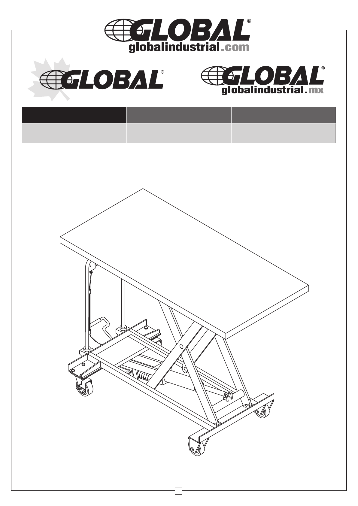
Long Deck Mobile Scissor Lift Table
Servicio de atención al Cliente
México: 01.800.681.6940
Model 988932
Service à la clientèle
Canada: 888-645-2986
1
012016
Page 2
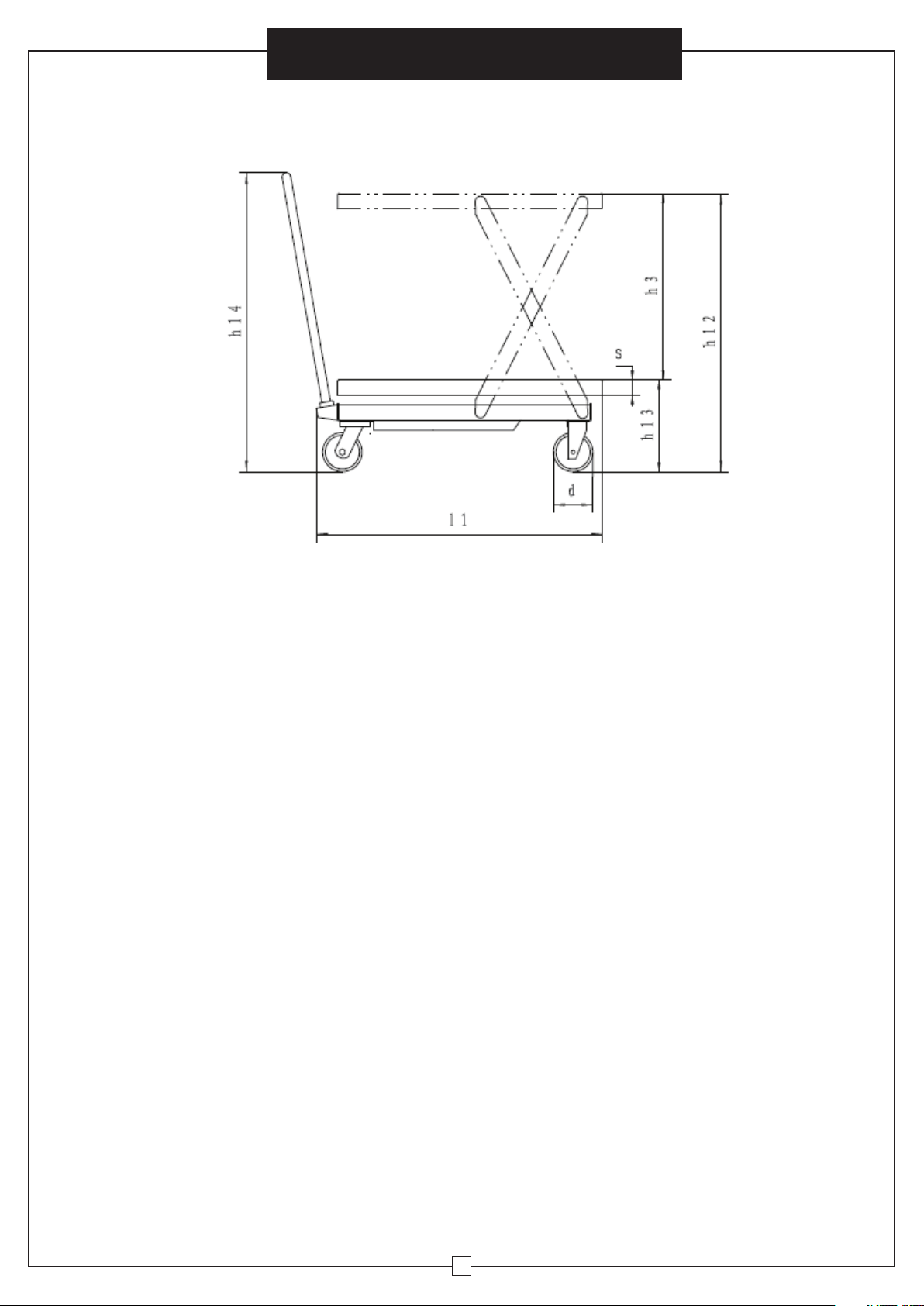
1. DRAWING
User’s Manual
Long Deck Mobile Scissor Lift Table
2. SPECIFICATIONS
Capacity 1100 lbs.
Max. lift height - h12 35.4 inches
Min. height of table - h13 12.2 inches
Lifting height - h3 23.2 inches
Table size - l x b5 x s 63 x 31.5 x 2 inches
Total height - h14 38 inches
Overall length - l1 66 inches
Foot pedal cycles to max height 55 cycles
Wheel diameter - d 5 inches
Weight 300 lbs.
Working volume of oil cylinder 255 milliliters
Oil capacity 400 milliliters
2
Page 3

User’s Manual
Long Deck Mobile Scissor Lift Table
3. OPERATION CONDITION
1. Lift table should be operated on a solid, even surface.
2. Operating temperature is: -20° to 40°C / -4° to 104°F.
4. WARNINGS
1. Please read and understand all instructions and safety warnings prior to assembling, installing,
operating, or performing maintenance on the described product. Be sure to observe all safety
information. Failure to comply with instructions may result in personal injury and/or property damage.
Retain instructions for future reference.
2. Be sure to operate lift table within rated load. Do not overload. Overloading will cause table damage.
3. Do not exceed rated capacity of 1100 lbs.
4. Do not sit or stand on lift table.
5. Inspect unit prior to use and do not operate if damaged or in poor condition.
6. Do not abuse or mishandle unit.
7.
Protect all extremities including hands, feet, and other body parts while operating or transporting lift table.
8. Do not place hands or feet near scissor mechanism.
9. Apply brakes and/or chock tires when lifting, loading, or unloading unit to prevent movement.
10. Verify stability and even distribution of loads prior to handling. DO NOT handle unsecured loads.
11. Do not leave loads on lift table for extended periods of time.
12. Lift table cannot be moved during operation.
13. Operate lift table on level, durable surfaces away from traffic.
14. When placing items on hoisted table, item weight should be loaded lightly and total weight must
be within rated load. (Safety valve operates in hoisting process only. If truck has been hoisted and
overloaded, safety valve will not operate and may cause damage.)
15. When loading and unloading items on hoisted table, do not drag content in cross direction. This may
cause risk stability.
16. During routine maintenance, safety mechanism (metal bar) must support fork arm preventing table
from accidental lowering for user safety. (Table should be unloaded during maintenance.)
17. Do not enter beneath lift table unless it is mechanically locked.
18. The warnings, precautions, and instructions discussed cannot cover all possible conditions and
situations that may occur. Failure to heed these warnings may result in property damage, personal
injury, and/or death.
19. Do not modify or alter this lift table. Modifications may cause improper functionality resulting in
possible injury or death.
5. OPERATION INSTRUCTIONS
1. Operator must be qualified, trained, and use caution when in use.
2. Step on foot lever to raise work table.
3. Slowly lift handle lever upward to open one-way valve. This will allow slow descent until desired or lowest
position is reached. Avoid lowering unit too fast or stopping suddenly as this may cause impact damage.
4. Release wheel brakes prior to moving truck.
5. During raised height operation, safety mechanism must be activated to prevent unintended lowering,
damage, or injury.
6. If unit is lifted, moved, or turned away from safety mechanism prior to lowering, return metal bar back
to its initial position.
7. The warnings, precautions, and instructions discussed cannot cover all possible conditions and
situations that may occur.
8. Failure to heed these warning may result in property damage, personal injury, and/or death.
3
Page 4

User’s Manual
Long Deck Mobile Scissor Lift Table
6. MAINTENANCE AND GENERAL CARE
It is important to conduct necessary maintenance and upkeep to prolong service life and safety
of lift table. Please check following items prior to table operation:
1. Verify lift table has no distortion or bending in various positions.
2. Inspect truck brake and wearing condition of wheels.
3. Check hydraulic system for oil leakage.
4. If any failure exists, lift table should be repaired prior to use.
5. Replace hydraulic oil every twelve months. Choose the following or a similar specifications of
hydraulic oil according to the various climate conditions:
a) YBN32 is adaptive under the environment temperature of -10~+40°C;
b) YCN32 is adaptive under the environment temperature of -20~+40°C.
6. Hydraulic oil change methods:
a) Remove sealing screw 11 of the attached drawing (See page 5.) with wrench.
b) Raise hand knob.
c) Remove screw 35 of oil plug and fill in hydraulic oil. (See page 5.)
7. OPERATION TROUBLESHOOTING
Faults Causes Troubleshooting
Table cannot be raised or lifting
height is insufficient.
Table rises then descends.
Table does not descend.
1. Steel ball (32) of the checkvalve is not closed down.
2. Firing pin (28) withstands
the steel ball (16).
3. Short of hydraulic oil. 3. Add sufficient hydraulic oil.
1. Steel ball (23) (24) (16)
of the check-valve is not
closed down.
2. Firing pin (28) withstands
the steel ball (16).
Firing pin travel (28) is
insufficient to open steel
ball (16).
1. Clean valve opening and
steel ball.
2. Adjust steel wire rope
tension rate to set firing pin
at a suitable location and
add or fill lubricant to pin roll
(30).
1. Clean valve opening and
steel ball.
2. Adjust steel wire rope
tension rate to set firing pin
at a suitable location and
add or fill lubricant to pin roll
(30).
Adjust steel wire rope tension
rate to set firing pin at a
suitable location and add or fill
lubricant to pin roll (30).
Oil leakage at the firing pin. O-ring (29) is damaged. Change the O-ring (29)
Oil leakage at pump (2), pump core,
(5) and piston rod (44).
Seal rings (1)(3)(47)(48) are
damaged.
4
Change the seal ring (1)(3)(47)
(48).
Page 5

Long Deck Mobile Scissor Lift Table
User’s Manual
ASSEMBLY (TYPE1)
See Parts List A
5
Page 6

Long Deck Mobile Scissor Lift Table
User’s Manual
ASSEMBLY
Parts List A
No. Description Qty.
1 Handle bar 1
2 Washer 2
3 Washer12 2
4 Bolt M12 x 30 2
5 Bolt M8 x 22 8
6 Washer 8 19
8 Washer 8 11
9 Nut M8 11
10 Universal wheel 5" 2
11 Frame 1
12 Shaft 2
13 Bush 4
14 Hollow shaft 2
15 Bearing 6203 4
16 Wheel 5" 2
17 Retaining ring for axle 12 2
18 Pump 1
19 Shaft 1
20 Washer 1
21 Retaining ring for axle 10 1
22 Retaining ring for axle 20 2
23 Retaining ring 1
24 Shaft 1
25 Retaining ring 1
26 Connecting rod 1
27 Cushion 1
28 Bolt M8 x 30 1
29 Pedal rod 1
30 Table 1
31 Washer 2
32 Roller 2
33 Washer 16 4
34 Retaining ring for axle 16 6
35 Knighthead 2
36 Arm 1
37 Roller 2
38 L-Pin 4
39 Washer 6 4
40 Screw M6 x 10 4
41 Pin 1
HANDLE
Parts List
No. Description Qty.
42 Pin 6 x 30 1
43 Handle 1
44 Nut M8 1
45 Screw 1
46 Pull Rod 1
6
Page 7

Long Deck Mobile Scissor Lift Table
User’s Manual
PUMP
See Parts List B
Part # 26 can be used as the pressure measure interface of the system.
7
Page 8

User’s Manual
Long Deck Mobile Scissor Lift Table
ASSEMBLY
Parts List B
No. Description Qty. No. Description Qty.
1 O-ring 22.4 x 2.65 1 25 Steel ball 1/2 (12.7) 1
2 Pump cylinder 1 26 Screw M16 x 18 1
3 YX-Seal ring 1 27 Strike pin 1
4 Dust ring 1 28 O-ring 6.9 x 1.8 2
5 Pump plunger 1 29 Shaft 1
6 Spring 1 30 Filter 1
7 Spring seat 1 31 O-ring 77.5 x 3.55 2
8 Retaining ring for axle 10 1 32 Rectangular section ring 1
9 Joint plate 2 33 Cylinder 1
10 Pin 1 34 Housing 1
11 Plug 1 35 Screw 1
12 Copper washer 20 1 36 Retaining ring for axle 25 1
13 Damp valve 1 37 Washer 1
14 Spring 1 38 O-ring 3.5 x 3.55 1
15 Spring seat 1 39 Cup packing 1
16 Steel ball 6.35 2 40 Bush 1
17 Steel ball 4.5 1 41 O-ring 20 x 2.65 1
18 Spring seat 1 42 Piston rod 1
19 Spring 1 43 Cylinder cap 1
20 Adjusting screw 1 44 O-ring 31.5 x 3.55 1
21 O-ring 5 x 2.65 2 45
22 Cover ring 1 46 Base 1
23 Steel ball 9.5 1 47 Lever plate 1
24 Spring 1 48 Retaining ring for axle 8 1
J-shaped steel frame rubber
32 x 45 x 6.5
1
8
 Loading...