

Page 1
globalindustrial.com
1
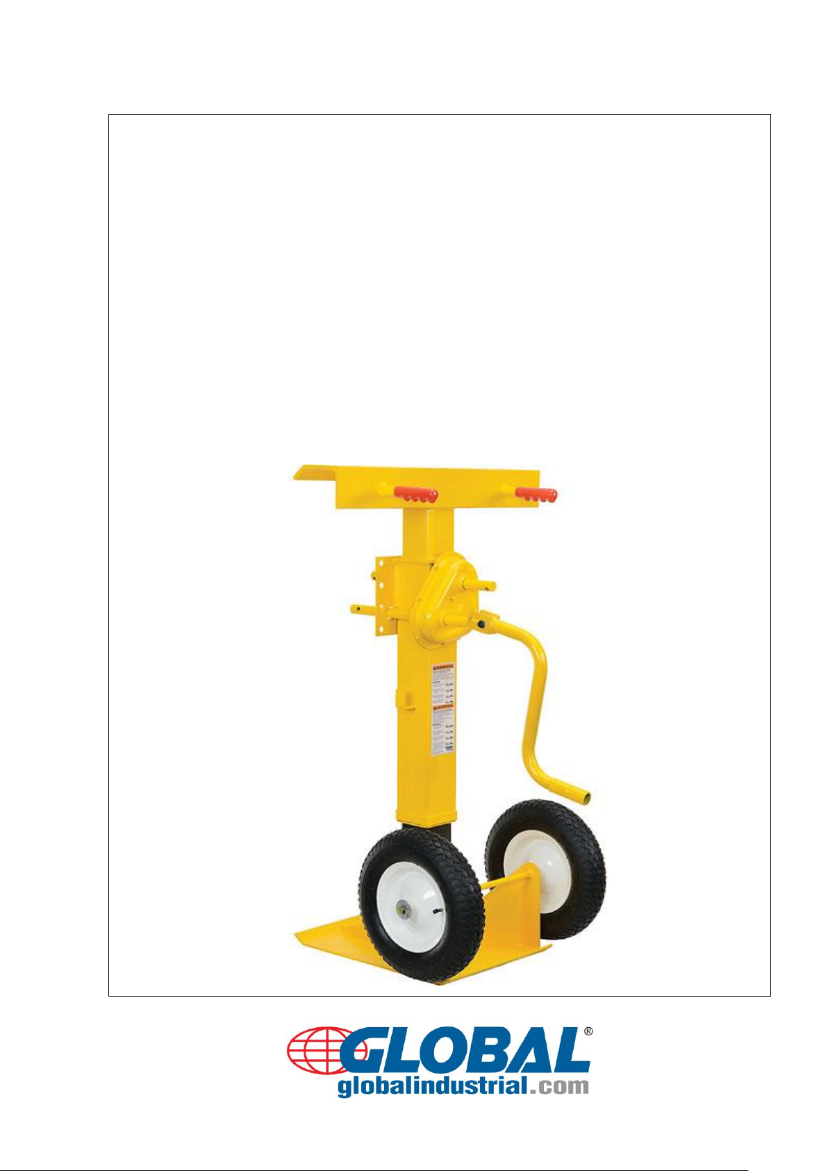
USER’S GUIDE & MAINTENANCE
Trailer Stabilizing Jacks
Model No. 985432 (Pneumatic)
Model No. 985433 (Semi-Pneumatic)
Page 2

globalindustrial.com
2
1. Specifications……………………………………………….…
3
2. Use Instructions……………………………………………....
3-4
3. Routine Maintenance and Safety Checks…….…………..
5
4. Exploded Parts Diagram……………………………………..
6
5. Label Placement Diagram……………………………………
7
CONTENTS
WARNING
Improper or careless use of this product might result in death or serious personal injuries sustained by
the operator and bystanders.
Failure to read and understand this manual before using or servicing a trailer stabilizing jack is
misuse. Any person who will use or maintain this product must be familiar with all instructions and
warnings in this manual.
DO NOT perform maintenance on or repair a loaded (in use) trailer stabilizing jack.
DO NOT use this product unless all labels are in place and legible.
DO NOT use a stabilizing jack if it is damaged.
ONLY use the stabilizing jack on compacted, improved surfaces (i.e. concrete) that are even and
level. This product will not stabilize trailers parked on uneven or sloped ground.
DO NOT use a stabilizing jack to support trailers. This jack is designed to stabilize trailers that are
supported by a landing gear (trailer dolly jack). Never use a stabilizing jack without deployed landing
gear in normal condition.
ONLY qualified maintenance personnel should maintain and repair this product. Improperly
maintained stabilizing jacks might become unsafe to use.
DO NOT modify a trailer stabilizing jack in any way without first obtaining written authorization from
GLOBAL.
Page 3

globalindustrial.com
3
Model
985433
985432
Static Capacity (lbs.)
100,000
100,000
Lifting Capacity (lbs.)
50,000
50,000
Color finish
Yellow
Yellow
Assembly
Assembled
Assembled
Construction
Steel
Steel
Max Height (inches)
55
55
Min Height (inches)
41
41
Wheel Diameter
16” Semi- Pneumatic
16” Pneumatic
Net Weight (lbs./kg)
210/94
210/94
1. SPECIFICATIONS
2. USE INSTRUCTIONS
The standard model trailer stabilizing jack is intended to be used to support the ends of a semitrailer
that is parked against a loading dock and not connected to a truck’s fifth-wheel. The semitrailer must
be situated on a flat, stable, improved (preferably concrete) surface.
The load rating in pounds is shown on the information label located on the side of the jack. Two ratings
appear on the label:
1) A static rating= how much weight the jack will stabilize;
2) A lifting rating= how much weight the screw mechanism of the jack can lift.
NOTE: The need to use trailer stabilizing jacks, the number necessary, and the exact placement of
jacks under the semitrailer must be determined by a qualified person responsible for the loading or
unloading of the trailer.
Page 4

globalindustrial.com
4
The following is a list (not all -inclusive) of circumstances under which use of trailer jack is
recommended:
To reduce the risk of the semitrailer’s landing gear failure.
To reduce the risk that the front of the semitrailer might tend to tip up when a fork truck enters the
rear of the semitrailer, such as with trailers having axles that are further away from the dock than
is typical.
The heavier the fork truck and load, the more likely it is that a trailer stabilizing jack will be needed.
Shorter semitrailers are more likely to need two jacks--one under each corner of the nose end.
WARNING: Improper or careless use of this product might result in death or serious personal injuries
sustained by the operator and bystanders. Before installing stabilizing jacks beneath a semitrailer:
1) The jack must be entirely and stably supported by its landing gear.
2) The trailer wheels must be properly immobilized to resist creep or roll.
3) The surface on which the jacks will be used must be even, level, compacted and improved
(concrete) to prevent the jack from sinking into the ground.
4) Confirm that the underside of the trailer is sound where the stabilizing jacks will contact it. If the
point of contact is unsound, the jack might break through the trailer.
5) DO NOT exceed the load ratings!
NOTE: Additional stabilizing jacks might be required under the rear corners of the semitrailer if the
distance from the rear axle to the back end of the semitrailer is more than 1/4 of the overall length of
the trailer.
Adjust the height of the jack so that the top cap of the jack presses firmly against the underside of the
semitrailer frame. However, the trailer landing gear must at all times remain in solid contact with the
ground in order to provide support for the front end of the trailer.
Jacks must be removed before backing a tractor underneath the semitrailer. To remove a trailer jack,
lower the top cap so that it no longer contacts the bottom of the trailer; then tip the jack backwards and
roll it out from under the trailer.
Page 5

globalindustrial.com
5
3. ROUTINE MAINTENANCE AND SAFETY CHECKS
Only qualified individuals trained to inspect and maintain stabilizing jacks should perform inspections
and maintenance. Inspect the jack as described in parts A and B below.
WARNING: If damage is evident, or if any problems are discovered during an inspection, immediately
tag the jack “Out of Service” and remove it from service UNTIL it is restored to normal operation
condition.
(A) INSPECT THE JACK FOR THE FOLLOWING CONDITIONS (DAILY):
1. Visible damage to the screw, base, or screw hub.
2. Free movement of the top cap.
3. Oil leaks.
(B) INSPECT THE FOLLOWING COMPONENTS AT LEAST ONCE A MONTH. DO NOT use the jack
until it is restored to normal operation condition.
1. Screw threads
a) Determine if threads are adequately greased: apply a standard bearing grease to the screw
threads. Fully extend the screw and apply grease liberally to the threads; then wind the screw into
the jack to coat the threads. In colder climates, synthetic grease will reduce the amount of effort
required to install the jack but is optional. Remove grease from the frame and handles before
returning the jack to service.
b) Inspect threads for severe wear or damage: if the screw wobbles inside the screw hub, the screw
assembly is significantly worn and should be replaced before returning the jack to service.
2. Screw adjustment mechanism. The mechanism should operate smoothly.
3. Jack frame. Examine the jack for cracked welds or metal fatigue.
4. Wheels. Axles, or wheel bearings: Inspect for looseness, excessive wear, or damage.
5. Handle grips. Damaged, loose, or missing, install adhesive to the inside of the grips and reinstall
them if they become loose.
6. Labels. The jack should be labeled at all times as shown in the diagram. Replace any label that is
damaged or not easily readable.
Page 6

6
ITEM NO.
DESCRIPTION
QTY.
1
30”L*6”W Landing
Surface
1
2
Red Handle
2
3
Axis
2
4
Gear Box
1
5
Folding Crank Handle
1
6
Guide Support
1
7
Support
1 8 Wheel axle
1
9
16”Semi-Pneumatic
Wheel or Pneumatic
Wheel
2
10
Pedestal
1
globalindustrial.com
4. EXPLODED PARTS DIAGRAM
Page 7

globalindustrial.com
7
5. LABEL PLACEMENT DIAGRAM
Each jack should be labeled at all times as shown in the diagram below.
Periodically inspect and clean (when necessary) the labels to maintain legibility. Replace any label that
is damaged or not easily readable.
LIMITED WARRANTY
We warrant this product to be free of defects in material and workmanship during the warranty period.
Our warranty obligation is to provide a replacement for a defective original part if the part is covered by
the warranty.
Validity of Warranty
The warranty period for original dynamic components is 30days, for wearing parts, the warranty period
is 30days. The warranty period begins on the date the product is shipped to the warrantee. If the product
was purchased from an authorized distributor, the period begins when the distributor ships the product.
globalindustrial.com
1-800-645-1232
11 Harbor Park Drive Port Washington, NY 11050
 Loading...