

Page 1
Page 2
Page 3

Page 4
Instruction Manual
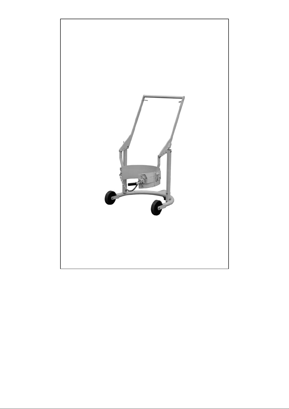
Mobile-Karrier
For 55 gallon (210 liters) steel drum
Note: Owner/Operator must read and understand this instruction
manual before using the Mobile-Karrier.
Page 5

Contents
Ⅰ. Structure and Relevant Parts Description
Ⅱ. Specifications
Ⅲ. Precaution
Ⅳ. Operation
Ⅴ. Maintenance
Ⅵ. Assembly
VII. Exploded View & Spare Parts
Page 6

THANK YOU FOR CHOOSING OUR MOBILE-KARRIER. FOR
YOUR SAFETY AND CORRECT OPERATION, PLEASE
CAREFULLY READ THE MANUAL BEFORE USE.
NOTE: All of the information reported herein is based on data
available at the time of printing. The factory reserves the right to
modify its own products at any time without notice or incurring in
any sanction. Please verify with the factory for possible updates.
Ⅰ. Structure and Relevant Parts Description
Item No. Description Remark
1 Chassis
2 Mast
3 Supporting hoop
4 Handle
5 Location pin
6 Fastening lever
7 Chain
8 Wheel
9 Caster
Page 7

10 Location lever
11 Lifting arm
12 Hanger plate
13 Adjustment hole
14 Pawl
15 Mobile hoop
16 Adjustment hole
17 Hook
Ⅱ. Specifications
Capacity
Drum dimension
Net Weight
800lbs
1/2” x 36”
22-
50kg
Ⅲ. Precaution
1. Always use the Mobile-Karrier on firm and flat floor.
2. Do not overload.
3. Only after chain firmly holds drum and location pin is correctly
positioned can the Mobile-Karrier be moved.
4. Do not pull location lever (Part No. 10) while moving the
Mobile-Karrier.
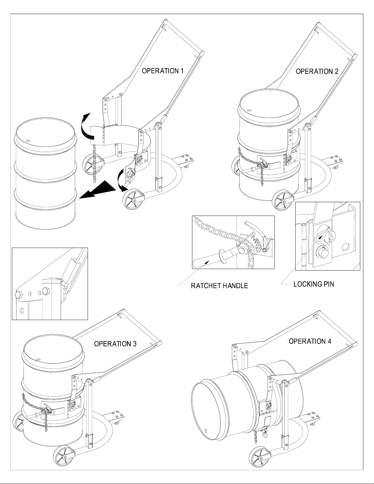
Ⅳ. Operation
1. Clamping drum
The mobile hoop (Part No. 15) is usually open due to being
supported by a spring. This does help to accepting the drum.
Push the Mobile-Karrier near to the drum that shall be lifted. While
pulling the location levers (Part No. 10), turn the handle (Part No. 4)
to locate supporting hoop (Part No. 3) in the middle of the drum.
Page 8

Release the location levers (Part No. 10) to lock the handle at this
appropriate position.
Turn the fastening lever (Part No. 6) counter-clockwise to make its
teeth upward. Fasten the chain (Part No. 7) and insert the chain
into the groove on the fastening lever (Part No. 6). Then turn the
lever (Part No. 6) clockwise quickly to make chain (Part No. 7)
embay the drum. Please make sure that the fastening lever (Part
No.6) is firmly locked by the pawl (Part No. 14).
2. Lifting drum
Press the handle (Part No. 4) and the drum will be lifted. When the
drum is lifted to the required position, release the handle (Part No. 4)
and the drum will be locked.
3. Transportation
Push/haul the handle (Part No. 4) to move the Mobile-Karrier to the
destination. (Of course, if necessary, operator can turn the handle
to change the Mobile-Karrier’s moving direction.)
4. Lower & release the drum
Press the handle (Part No. 4) slightly, and pull the location levers
(Part No. 10) at the same time. Then slowly lift the handle (Part No.
4) so as to lower the drum. When the drum reaches a firm surface
release the location levers (Part No. 10).
Page 9

Turn the fastening lever (Part No. 6) clockwise slightly so that the
pawl (Part No 14.) disengages. Release the fastening lever (Part
No. 6). Take the chain (Part No. 7) out the groove on the fastening
lever and hang it on the hook (Part No. 17).
Move away the Mobile-Karrier.
5. Rotate the drum
The Mobile-Karrier can rotate the drum from vertical to horizontal
position according to actual demand. Do the operation as follows.
Disengage the location pins (Part No. 5) and in the meantime turn
the drum by 90° by hand.
Turn the location pins so as to insert them into the corresponding
holes to lock the drum in the horizontal position.
Note: Before rotating the drum, press/lift the handle (Part No. 4) to
an appropriate height in case the drum bumps the ground.
6. Adjustment
If the supporting hoop is too high to hold the middle of the drum
while the handle (Part No. 4) is lifted to its max. height, it is
necessary to choose another appropriate hole on the handle.
If the drum cannot be lifted to required height while the handle (Part
Page 10

No. 4) is pressed to reach its min. height, it is necessary to choose
another appropriate hole on the lifting arm (Part No. 12).
Pull the location levers (Part No. 10) and slowly lift the handle (Part
No. 4) so as to lower the drum. When the drum reaches a firm
surface release the small levers (Part No. 10).
Remove the chain and move the Mobile-Karrier away from the
drum.
Ⅴ. Maintenance
1. Do routine check of the wearing condition of location pins (Part
No. 5) and replace the worn pins in time.
2. Do routine check of chassis, front wheel and rear caster.
3. Do routine check of clamping reliability of chain.
4. Do routine check of all the connecting parts such as pins and
fasteners.
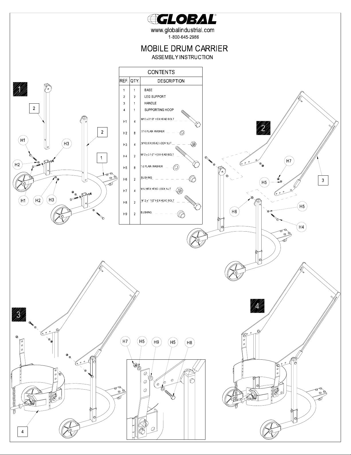
Ⅵ. Assembly
Some necessary tools must be prepared before assembly.
1. Take out all the subassemblies in following turns from carton.
a
b
c
d
e
Steel harness, washers, nuts and clamp
Chassis
Mast
Supporting hoop
Handle
collars
2. Assemble mast (b) on chassis (a) with screws, washers and
nuts.
3. Put steel harness (e) through the holes on the outsides of the
lifting arms (Part No 11.) and then fix it with fasteners (e).
Page 11

4. Put steel harness (e) through the holes on the hanger plates
(Part No 12.) and then fix it with fasteners (e).
VII. Exploded View & Spare Parts
Page 12

No. Description Qty No. Description Qty
1. Pin 2 26. Pin 1
2. Retaining ring 4 27. Retaining pin 1
3. Separate ring 4 28. Supporting hoop 1
4. Front wheel 2 29. Hanger plate 2
5. Bearing 4 30. Sliding pin
6. Chassis 1 31. Spring
7. Bolt 4 32. Sliding bush
8. Lock nut 4 33. Retaining ring
9. Rubber bush 1 34. Extension ring
10. Pawl
11. Retaining ring
12. Bolt
13. Spring
14. Dentation clip
15. Pin
16. Chain
17. Mobile hoop
18. Nut
1
35. Bolt
1
36. Separate ring
1
37. Bolt
1
38. Separate ring
1
39. Sliding block
1
40. Spring
1
41. Lever
1
42. Lifting arm
1
43. Tapper pipe
19. Hub for chain 2 44. Dentation claw
20. Door 1 45. Square plug
21. Bolt 1 46. Bolt
22. Pin 1 47. Lock nut
23. Lock nut 2 48. Mast
2
2
2
2
2
2
2
2
2
2
2
2
2
2
2
2
2
2
2
24. Spring 1 49. Back wheel 1
25. Washer 1 50.
 Loading...