

Page 1
globalindustrial.ca
Instruction Manual Manual de Instrucciones Manuel d'instruction
Distribucion Industrial Globales S DE RL DE CF
Customer Service
US: 1-800-645-2986
Servicio de atención al Cliente
México: 01.800.681.6940
Service à la clientèle
Canada: 888-645-2986
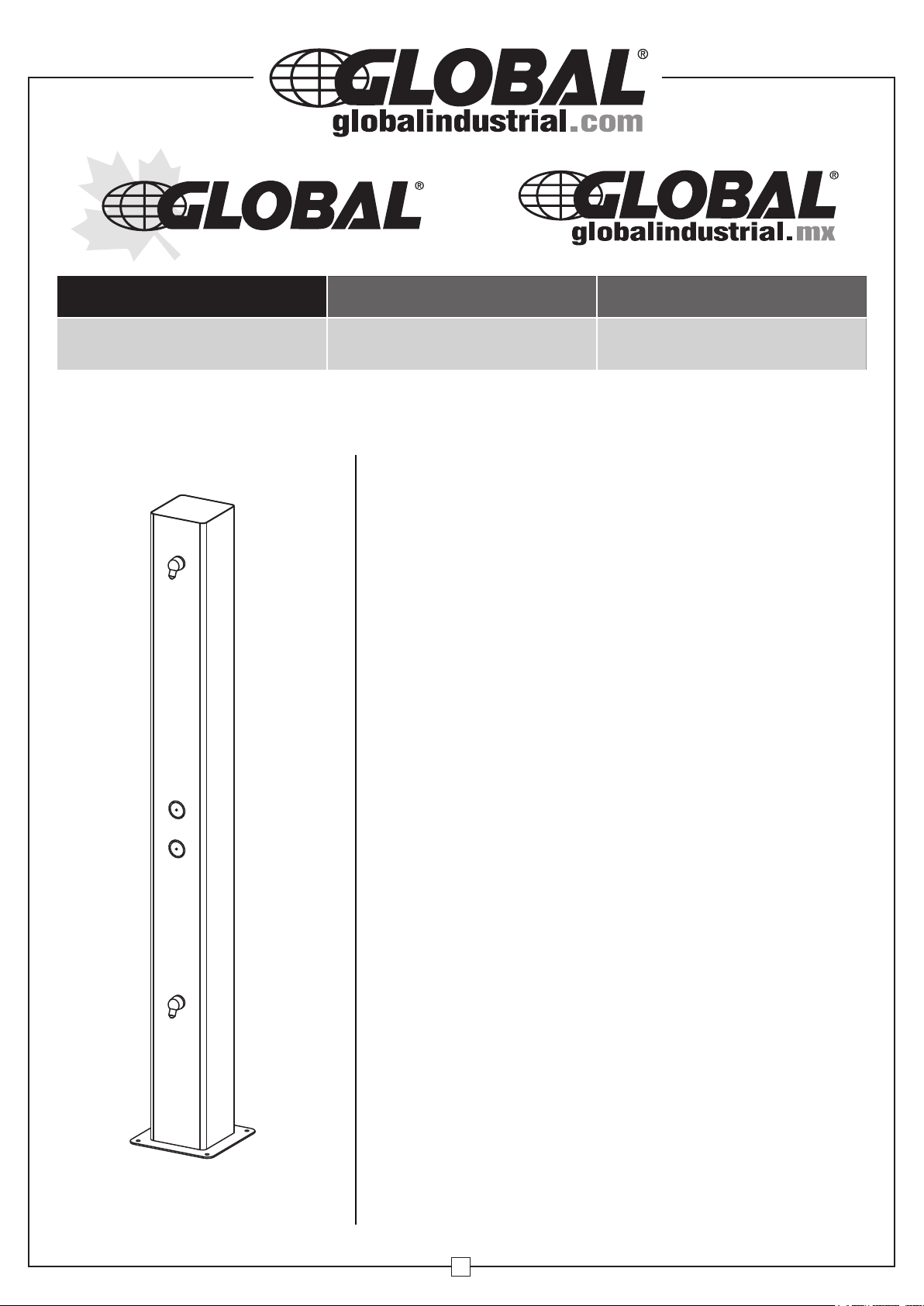
84" Outdoor 2 Nozzle Water Shower - Stainless Steel
Model 670434
WARNING
• All installation work must be performed by authorized
service personnel.
• Two or more people are recommended to lift and
install the unit.
• Check local codes for plumbing requirements prior
to installation.
• Refer to Rough-In Guide (page 4) prior to installation.
• Thoroughly flush all water supply lines of all foreign
matter before connecting to the fixture.
• Check for any leaks before use.
• DO NOT attempt to repair or replace any part of this
shower unless it is specifically recommended in this
manual. All other services should be referred to a
qualified technician.
• Shut-off water supply during installation to reduce the
risk of water damage.
• Freezing Caution: Before freezing temperatures occur,
refer to the Draining and Winterization section of this
manual (page 9) for proper preparation.
• This shower must be mounted on a flat, level surface
(concrete or otherwise) with an adequate support structure
and proper surface draining.
• Failure to follow safety warnings and/or
installation instructions will void warranty.
Note: This shower is designed to be installed on the
surface of an existing or new concrete slab. Included
are the necessary vandal-resistant stainless steel bolts
and washers needed to anchor this unit. All connections
are made inside the shower through the access doors,
as shown in the drawings within this manual. It is
recommended to install a shut-off valve (not included)
on the water supply.
1
Page 2
84” Outdoor 2 Nozzle Water Shower
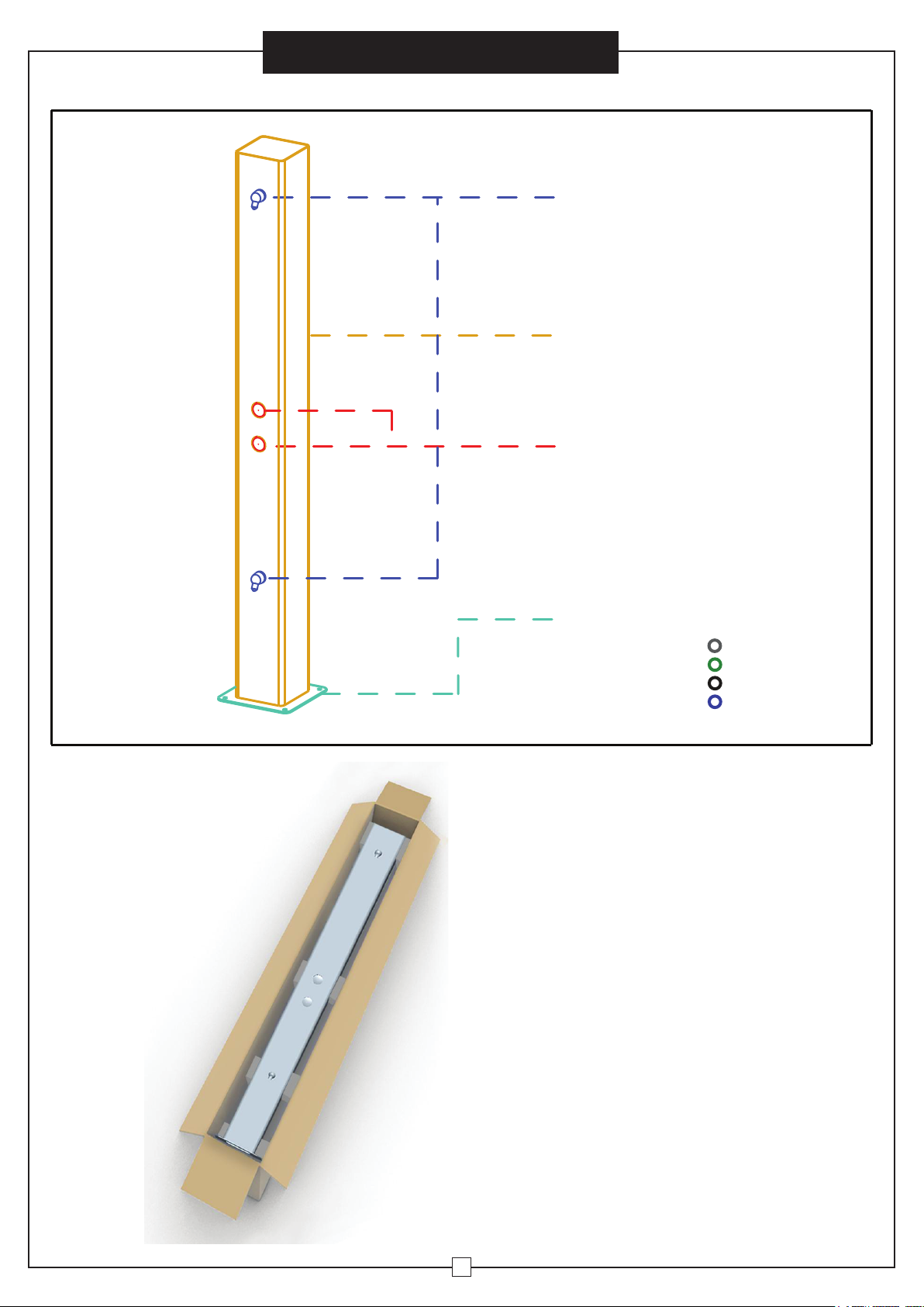
NOZZLES
BODY
PUSH BUTTONS
Instruction Manual
BASE
WWW .GLOB ALIND USTRI AL.CO M
Package Contents:
- SS Shower
- Hardware Bag
COLOR OPTIONS:
SS316
SS316 GREEN
SS316 BLACK
SS316 BLUE
2
Page 3
SPECIFICATIONS
Features :
316 Stainless ,
Heavy Duty, Vandal Resistant
Finis h: Stainless Steel Finish
Power: No Electrical Required
Bubbler Vandal Resis tant
Activation Type: Push Button
Mounting Type: Floor Mount/Free Standing
Product Dimensions:
12"L x 12"W x 84"H
Weight: 84.9 lbs.
Installation Location: Outdoor
No. of Nozzles: 2
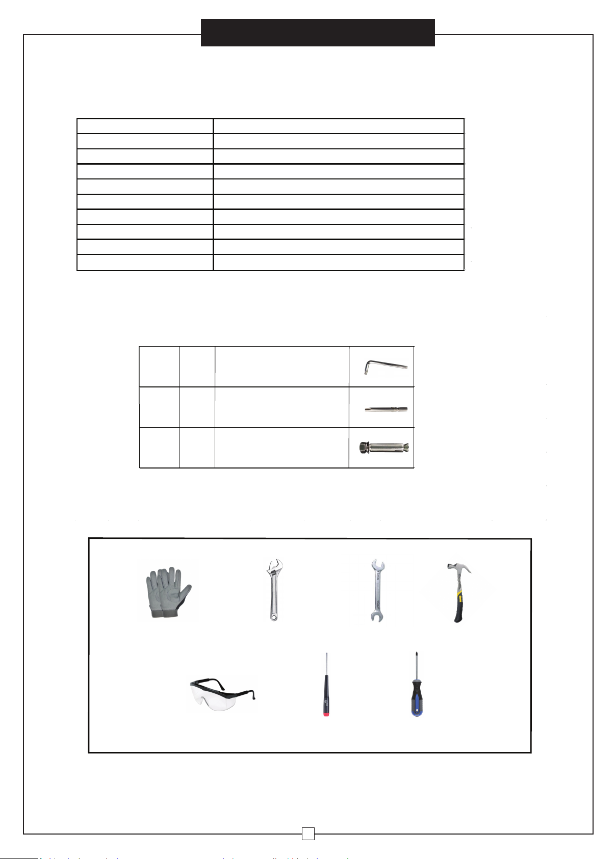
PART BREAKDOWN
84” Outdoor 2 Nozzle Water Shower
Instruction Manual
Ref. Qty. Descrip�on
H1 1
H2 1
H3 4
REQUIRED TOOLS
Safety Gloves
Torx Key Wrench
Torx Drill Bit
Anchor Kit
Adjustable Wrench
15-17mm
Wrench
Hammer
Safety Glasses
Small Flathead
Screwdriver
3
Phillips-Head
Screwdriver
Page 4

4 1/2''
120mm
4''
''
3 1/2
102mm
89mm
5 1/2''
137mm
84” Outdoor 2 Nozzle Water Shower
19 1/2''
499mm
9 1/2''
248mm
20 1/2''
526mm
20''
496mm
5 1/2''
137mm
B
Instruction Manual
• See Page 9 for Draining and Winterization
• Actual product configuration may vary based on model ordered.
12''
305mm
12''
304mm
10''
254mm
1/2''
12mm HOLES (4)
12''
12''
305mm
305mm
6''
152mm
FINISHED FLOOR
76 1/2''
1942mm
ORIFICE
HEIGHT
18''
454mm
ORIFICE
19 1/2''
495mm
HEIGHT
A
10''
254mm
INSIDE OPENING
10''
254mm
INSIDE OPENING
25°
84''
2133mm
6''
150mm
20''
39''
989mm
498mm
Rough-In Guide
LEGEND:
A = 3/8” O.D. UNPLATED COPPER TUBE CONNECT - SHUT-OFF VALVE BY OTHERS
B = ACESS PANEL (4-1/2” X 20-1/2”)
4
Page 5

Instruction Manual
84” Outdoor 2 Nozzle Water Shower
INSTALLATION
• It is recommended that 2 or more people install this unit.
This shower must be mounted on a flat, level surface (concrete or otherwise) with an adequate
•
support structure and proper surface draining.
• Locate and install plumbing through ground as required. Refer to Rough-In Guide (page 4)
for proper location and correct plumbing.
• Install a drainable shut-off valve (not included) if in a freezable environment.
1. REMOVE ACCESS PANELS
To gain access to the water line connections, remove the (3) access panels using the provided
torx key wrench (H1) or torx drill bit (H2) to remove all (18) M6 x 10 flat-head anti-theft screws
on back side of the unit:
Flat-head anti-theft screw
M6 x 10 (qty 18)
REMOVE
REMOVE
REMOVE
5
Page 6

Instruction Manual
84” Outdoor 2 Nozzle Water Shower
2. MOUNT SHOWER UNIT TO GROUND
• Locate and install plumbing through ground as required. Refer to Rough-In Guide (page 4)
for proper location and correct plumbing.
This shower must be mounted on a flat, level surface (concrete or otherwise) with an adequate
•
support structure and proper surface draining.
Position shower unit base over plumbing and secure to ground using provided anchor kit (H3)
mounting hardware (x4).
(H3) Anchor kit consists of:
- (4) M10 Nuts
- (4) M10 Lock Washers
- (4) M10 Standard Washers
- (4) M10 Anchors
H3
(qty 4)
Nut
Lock Washer
Standard Washer
Anchor
6
Page 7

Instruction Manual
84” Outdoor 2 Nozzle Water Shower
3. WATER INLET LINE CONNECTION BREAKDOWN:
• Install a shut-off valve (not included) on the water supply.
• All other internal water lines are preinstalled; see below illustration for reference.
• All water connections must comply with local codes.
SIDE VIEWFRONT VIEW
Vandal-Resistant
Nozzles
(preinstalled)
1/4" O.D.
Water Inlet
(preinstalled)
Inlet Adapter
(preinstalled)
Union T-Connector
(preinstalled)
3/8" O.D.
Water Inlet
(preinstalled)
Install Shut-off Valve
(Not Included)
7
Page 8

Union T-Connector
with Inlet Adapters
84” Outdoor 2 Nozzle Water Shower
38''
6''
Instruction Manual
Nozzle
Push Button
FIG. 1
Install Shut-off Valve
(Not Included)
3/8” O.D. TUBE CONNECT
COLD WATER SUPPLY
NOTE: WATERFLOW DIRECTION
40'' 24''
FIG. 2
OPERATION OF QUICK CONNECT FITTINGS
SIMPLY PUSH IN
SIMPLY PUSH IN
TUBE TO ATTACH
TUBE TO ATTACH
A B C
TUBE IS SECURED
TUBE IS SECURED
IN POSITION
IN POSITION
B CA
PUSH IN COLLET
PUSHIN COLLET
TO RELEASE TUBE
TO RELEASE TUBE
PUSHING TUBE IN BEFORE
PULLING IT OUT HELPS TO
RELEASE TUBE
• If shower is being installed in areas where cold temperatures may occur, all water inlet
lines are preinstalled with pipe insulation to help prevent freezing.
CAUTION: Before freezing temperatures occur, see Draining and Winterization section
of this manual (page 9) for proper preparation.
Note: Turn on water supply and check all connections for leaks and proper operation.
8
Page 9

Instruction Manual
84” Outdoor 2 Nozzle Water Shower
4. REINSTALL ACCESS PANELS
Reinstall all (3) access panels using the (18) M6 x 10 flat-head anti-theft screws preciously
removed from the shower unit.
WARNING: Flush all water supply lines thoroughly before initial use.
START-UP
Initial water flow may have sputter due to air in the water lines; this will be eliminated
once air is purged from all water lines. Press and hold the push button until a steady
water stream is achieved.
STREAM PRESSURE ADJUSTMENT
The water stream pressure is factory set at 35 PSI. If adjustment is required, insert a
small flathead screwdriver through the access hole in the center of the push button
and turn the adjustment screw. Turn clockwise to raise the stream height and
counterclockwise to lower the stream height.
CAUTION: The shower is rated for inlet water pressure of 20-105 PSI. A pressure reducing
regulator should be used if the inlet water supply exceeds 105 PSI. Any damage caused by
reason of connecting this product to supply line pressures lower than 20 PSI or higher than
105 PSI will void warranty.
DRAINING AND WINTERIZATION
• Before freezing temperatures occur, turn off the water at the shut-off valve, disconnect
the water supply line tubing and blow out lines. Press down on push button to release any
air pressure that may remain in the lines.
• DO NOT allow water lines to freeze. Cracked or broken components due to freezing are
not covered by warranty.
9
 Loading...