

Page 1
Congratulations
By purchasing a Gigaset, you have chosen a brand that is fully committed
to sustainability. This product’s packaging is eco-friendly!
To learn more, visit www.gigaset.com.
Page 2

Page 3

Web configurator – Setting the phone using a PC
The Web configurator is the Web interface for your phone. It allows you to select the
settings for your Gigaset DX800A all in one via your PC's Web browser. You can use
your phone's Web configurator to do the following:
¤ Configure access from your phone to the local network (IP address, gateway to
the Internet).
¤ Configure the phone number/telephone connections of your phone. Assign
the connections as send and receive connections to your base and all connected handsets.
¤ Load new firmware onto your phone if necessary.
¤ Use Internet services: Enable access to an online directory and display text
information on the base (info services).
¤ Synchronise the date/time on the telephone with a time server on the
Internet.
¤ Copy the contacts from the Outlook directory on your PC to the local directory
on your base.
Or:
Back up your phone directories on a PC. Copy the entries to your Outlook
directory.
¤ Obtain information about the status of your phone (firmware version, MAC
address, phone numbers, connected handsets etc.).
¤ Back up your phone configuration on the PC and reload the back-up to the
base when required.
1
Page 4

Contents
Web configurator – Setting the phone using a PC . . . . . . . . . . . . . . . . . . . 1
Web configurator menu . . . . . . . . . . . . . . . . . . . . . . . . . . . . . . . . . . . . . . . . . . . . 5
Connecting the PC with the telephone's Web configurator . . . . . . . . . . . 6
Establishing a connection via the base's IP address . . . . . . . . . . . . . . . . . . . . . . . . . . . . . 6
Establishing a connection via Gigaset config . . . . . . . . . . . . . . . . . . . . . . . . . . . . . . . . . . . 7
Logging in to/off the Web configurator . . . . . . . . . . . . . . . . . . . . . . . . . . . . . 8
Logging in, setting the interface language . . . . . . . . . . . . . . . . . . . . . . . . . . . . . . . . . . . . . 8
Logging off . . . . . . . . . . . . . . . . . . . . . . . . . . . . . . . . . . . . . . . . . . . . . . . . . . . . . . . . . . . . . . . . . . . 9
Understanding the structure of the Web configurator pages . . . . . . . . 10
Menu bar . . . . . . . . . . . . . . . . . . . . . . . . . . . . . . . . . . . . . . . . . . . . . . . . . . . . . . . . . . . . . . . . . . . . 10
Using the navigation area . . . . . . . . . . . . . . . . . . . . . . . . . . . . . . . . . . . . . . . . . . . . . . . . . . . . 11
Using the working area . . . . . . . . . . . . . . . . . . . . . . . . . . . . . . . . . . . . . . . . . . . . . . . . . . . . . . 11
Using the buttons . . . . . . . . . . . . . . . . . . . . . . . . . . . . . . . . . . . . . . . . . . . . . . . . . . . . . . . . . . . . 12
Opening Web pages . . . . . . . . . . . . . . . . . . . . . . . . . . . . . . . . . . . . . . . . . . . . . . . . . . . . . . . . . 13
IP Configuration – Connecting to the LAN . . . . . . . . . . . . . . . . . . . . . . . . . . 14
Assigning the IP address . . . . . . . . . . . . . . . . . . . . . . . . . . . . . . . . . . . . . . . . . . . . . . . . . . . . . 14
Allowing access from other networks . . . . . . . . . . . . . . . . . . . . . . . . . . . . . . . . . . . . . . . . . 15
Entering an HTTP proxy server
(only when connected to an internal company network) . . . . . . . . . . . . . . . . . . . . . . 16
Telephony – Connections:
Configuring phone connections . . . . . . . . . . . . . . . . . . . . . . . . . . . . . . . . . . . 17
Setting the fixed line network connection . . . . . . . . . . . . . . . . . . . . . . . . . . . . . . . . . . . . 20
Configuring the Gigaset.net connection . . . . . . . . . . . . . . . . . . . . . . . . . . . . . . . . . . . . . . 21
Configuring the VoIP connection . . . . . . . . . . . . . . . . . . . . . . . . . . . . . . . . . . . . . . . . . . . . . 22
Configuring a GSM connection . . . . . . . . . . . . . . . . . . . . . . . . . . . . . . . . . . . . . . . . . . . . . . . 29
Telephony – Audio:
Optimising voice quality for VoIP connections . . . . . . . . . . . . . . . . . . . . . 30
Saving settings on the phone . . . . . . . . . . . . . . . . . . . . . . . . . . . . . . . . . . . . . . . . . . . . . . . . 33
Voice quality and infrastructure . . . . . . . . . . . . . . . . . . . . . . . . . . . . . . . . . . . . . . . . . . . . . . 33
Telephony – Number Assignment:
Assigning send and receive connections . . . . . . . . . . . . . . . . . . . . . . . . . . . 34
Assigning receive/send connections to bases/handsets,
changing internal names . . . . . . . . . . . . . . . . . . . . . . . . . . . . . . . . . . . . . . . . . . . . . . . . . . . . . 35
Assigning receive/send connections to the FAX port . . . . . . . . . . . . . . . . . . . . . . . . . . 37
Assigning receive connections to answering machines . . . . . . . . . . . . . . . . . . . . . . . . 38
Activating the fixed line network connection
as an alternative connection . . . . . . . . . . . . . . . . . . . . . . . . . . . . . . . . . . . . . . . . . . . . . . . . . 39
Telephony – Ca ll Divert:
Activating Call Divert for VoIP connections . . . . . . . . . . . . . . . . . . . . . . . . . 40
2
Page 5

Telephony – Dialling Plans: Entering an access code . . . . . . . . . . . . . . . . 41
Telephony – Dialling Plans:
Entering your own area code and extra codes . . . . . . . . . . . . . . . . . . . . . . 41
Telephony – Dialling Plans:
Defining dialling plans – cost control . . . . . . . . . . . . . . . . . . . . . . . . . . . . . . 43
Defining dialling plans . . . . . . . . . . . . . . . . . . . . . . . . . . . . . . . . . . . . . . . . . . . . . . . . . . . . . . . 44
Activating/deactivating dialling plans . . . . . . . . . . . . . . . . . . . . . . . . . . . . . . . . . . . . . . . . 45
Deleting dialling plans . . . . . . . . . . . . . . . . . . . . . . . . . . . . . . . . . . . . . . . . . . . . . . . . . . . . . . . 45
Telephony – Network Mailboxes:
Entering the network mailbox, activating deactivating
the network mailbox . . . . . . . . . . . . . . . . . . . . . . . . . . . . . . . . . . . . . . . . . . . . . 46
Entering numbers . . . . . . . . . . . . . . . . . . . . . . . . . . . . . . . . . . . . . . . . . . . . . . . . . . . . . . . . . . . . 46
Activating/deactivating the network mailbox . . . . . . . . . . . . . . . . . . . . . . . . . . . . . . . . . 46
Telephony – Ad v a nced Settings:
Setting DTMF signalling for VoIP . . . . . . . . . . . . . . . . . . . . . . . . . . . . . . . . . . 47
Telephony – Ad v a nced Settings:
Defining recall functions for VoIP (hook recall) . . . . . . . . . . . . . . . . . . . . . 48
Telephony – Advanced Settings:
Configuring call transfer via VoIP . . . . . . . . . . . . . . . . . . . . . . . . . . . . . . . . . . 49
Telephony – Advanced Settings:
Defining local communication ports for VoIP . . . . . . . . . . . . . . . . . . . . . . . 50
E-Mail:
Making e-mail settings . . . . . . . . . . . . . . . . . . . . . . . . . . . . . . . . . . . . . . . . . . . 52
Services – Info Services:
Configuring/activating the display . . . . . . . . . . . . . . . . . . . . . . . . . . . . . . . . 53
Services – Online Directory:
Selecting an online directory . . . . . . . . . . . . . . . . . . . . . . . . . . . . . . . . . . . . . . 54
Directory Transfer:
Deleting directories and loading to/from the PC. . . . . . . . . . . . . . . . . . . . 55
Loading the directory file from the PC to the base/handset . . . . . . . . . . . . . . . . . . . . 56
Loading the directory from the base/handset to the PC . . . . . . . . . . . . . . . . . . . . . . . 56
Deleting the directory . . . . . . . . . . . . . . . . . . . . . . . . . . . . . . . . . . . . . . . . . . . . . . . . . . . . . . . 56
Understanding directory file content (vcf file) . . . . . . . . . . . . . . . . . . . . . . . . . . . . . . . . . 57
Management – Date & Time:
Copying the date/time from the time server . . . . . . . . . . . . . . . . . . . . . . . 58
Management – Miscellaneous:
Resgistering handsets . . . . . . . . . . . . . . . . . . . . . . . . . . . . . . . . . . . . . . . . . . . . 60
Management – Miscellaneous:
3
Page 6

Reducing radiation – activating/deactivating Eco Mode . . . . . . . . . . . . 60
Management – Miscellaneous:
Changing system PIN of the phone . . . . . . . . . . . . . . . . . . . . . . . . . . . . . . . . 61
Management – Miscellaneous:
Activating VoIP status message display . . . . . . . . . . . . . . . . . . . . . . . . . . . . 61
Management – Save & Restore:
Saving and restoring system settings . . . . . . . . . . . . . . . . . . . . . . . . . . . . . . 62
Saving the settings for the base on your PC . . . . . . . . . . . . . . . . . . . . . . . . . . . . . . . . . . . 62
Loading the settings from a file on the PC to the base . . . . . . . . . . . . . . . . . . . . . . . . . 62
Management – Firmware Update:
Updating the base's firmware . . . . . . . . . . . . . . . . . . . . . . . . . . . . . . . . . . . . . 63
Starting the firmware update manually . . . . . . . . . . . . . . . . . . . . . . . . . . . . . . . . . . . . . . . 63
Activating/deactivating the automatic version check . . . . . . . . . . . . . . . . . . . . . . . . . . 65
Querying the phone status . . . . . . . . . . . . . . . . . . . . . . . . . . . . . . . . . . . . . . . . 66
IP Configuration area . . . . . . . . . . . . . . . . . . . . . . . . . . . . . . . . . . . . . . . . . . . . . . . . . . . . . . . . 66
Software area . . . . . . . . . . . . . . . . . . . . . . . . . . . . . . . . . . . . . . . . . . . . . . . . . . . . . . . . . . . . . . . . 66
Fixed Line area . . . . . . . . . . . . . . . . . . . . . . . . . . . . . . . . . . . . . . . . . . . . . . . . . . . . . . . . . . . . . . . 66
VoIP Status area . . . . . . . . . . . . . . . . . . . . . . . . . . . . . . . . . . . . . . . . . . . . . . . . . . . . . . . . . . . . . . 67
Gigaset.net area . . . . . . . . . . . . . . . . . . . . . . . . . . . . . . . . . . . . . . . . . . . . . . . . . . . . . . . . . . . . . 67
GSM Connections area . . . . . . . . . . . . . . . . . . . . . . . . . . . . . . . . . . . . . . . . . . . . . . . . . . . . . . . 68
Registered Handsets area . . . . . . . . . . . . . . . . . . . . . . . . . . . . . . . . . . . . . . . . . . . . . . . . . . . . 68
Date and Time area . . . . . . . . . . . . . . . . . . . . . . . . . . . . . . . . . . . . . . . . . . . . . . . . . . . . . . . . . . 68
Index . . . . . . . . . . . . . . . . . . . . . . . . . . . . . . . . . . . . . . . . . . . . . . . . . . . . . . . . . . . . 69
4
Page 7
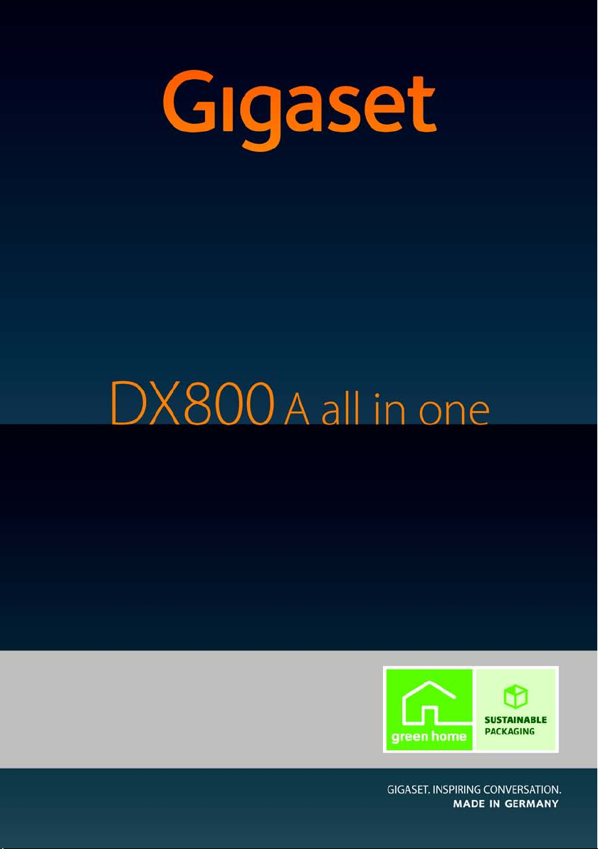
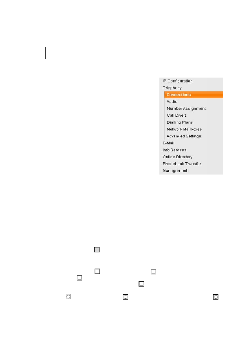
Web configurator menu
Home
Settings IP Configuration
Telephony Connections
Audio
Number Assignment
Call Divert
Dialling Plans
Network Mailboxes
Advanced Settings
¢ page 14
¢ page 17
¢ page 30
¢ page 34
¢ page 40
¢ page 41
¢ page 46
¢ page 47
E-Mail
Info Services
Online Directory
Directory Transfer
Management Date & Time
Status Device
Miscellaneous
Save & Restore
Firmware Update
¢ page 52
¢ page 53
¢ page 54
¢ page 55
¢ page 58
¢ page 60
¢ page 62
¢ page 63
¢ page 66
5
Page 8

Connecting the PC with the telephone's Web configurator
Prerequisites:
u A standard Web browser is installed on the PC e.g., Internet Explorer version 6.0
or higher, or Firefox version 1.0.4 or higher.
u The phone and PC are directly connected with each other via a router. The set-
tings of any existing firewall installed on your PC allow the PC and phone to
communicate with each other.
There are two ways of connecting your PC to the Web configurator of the base:
u Via the phone's IP address in the local network;
u Via the Gigaset configuration service, if the phone and PC are connected to the
Internet (
u Depending on your VoIP provider, it is possible that you will be unable to
u The phone is not blocked while you select your settings in the Web configu-
u While you are connected to the Web configurator, it is blocked to other users.
Establishing a connection via the base's IP address
¤ Establish the current IP address of the base or handset. It is displayed when you
open the following menu:
v
Your phone's IP address can change if you have activated dynamic IP address
assignment (¢ page 14).
¢ page 7).
Please note
change individual settings in the Web configurator.
rator. You can make calls with your phone or modify settings at the same
time.
It cannot be accessed by more than one user at any time.
¢ Ï Settings ¢ System ¢ Local Network (enter PIN if necessary)
Warning
If one of the four parts of the IP address contains leading zeros (e.g., 002), these
zeros must not be entered in the Web browser address field. Otherwise, the Web
browser will not be able to establish a connection to the Web configurator.
Example: The IP address 192.168.002.002 is displayed on the base. 192.168.2.2
should be entered in the address field.
¤ Launch the Web browser on your PC.
¤ Enter http:// and the telephone's current IP address (for example:
http://192.168.2.2) into the address field of the Web browser.
¤ Press the return key.
A connection is established to the phone's Web configurator.
6
Page 9

Establishing a connection via Gigaset config
Prerequisite: Your PC and base are connected to the Internet.
¤ Launch the Web browser on your PC.
¤ Enter one of the following URLs into the Web browser's address field:
http://www.gigaset-config.com
¤ Press the return key.
You will receive a message stating that the connection has been forwarded to your
base.
If several Gigaset phones can be reached via your Internet connection, you are
asked which of these phones you would like to be connected to.
After successfully forwarding the connection, the Web configurator's Login page is
displayed in the Web browser.
Please note
The connection between the PC and the Web configurator is a local connection
(LAN connection). The Internet is only accessed to establish the connection.
7
Page 10
Logging in to/off the Web configurator
V
Logging in, setting the interface language
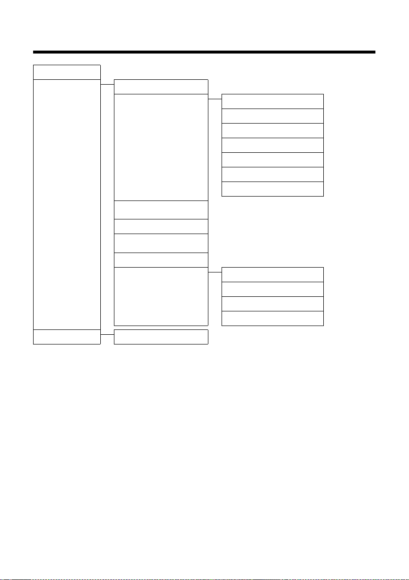
Once you have successfully established the connection, the Login Web page is displayed in the Web browser.
Figure 1 Start screen
You can select the language you want the menus and Web configurator dialogues
to be displayed in. The language that is currently selected is displayed in the first
field on the Web page.
¤ If necessary, click to open the list of available languages.
¤ Select the language.
The Web page is reloaded in the selected language.
¤ Enter your base's system PIN (default setting: 0000) in the bottom field on the
Web page to access the Web configurator functions.
¤ Click OK.
Once you have successfully logged in, the Home Web page opens with general
information on the Web configurator.
If you enter an incorrect system PIN, a corresponding message is displayed. You are
prompted to re-enter the PIN.
If you enter an incorrect system PIN a second time, the PIN field is blocked for a
short time (greyed out). The duration of the block will double each time a PIN is subsequently entered incorrectly.
8
Page 11

u If the system PIN is still set as 0000 on the base (default setting), you will be
u If you do not make any entries for a lengthy period (approx. 10 minutes), you
u Any entries that you did not save on the phone before automatic log-off will
Logging off
In the menu bar (¢ page 10) at the top right of every Web page in the Web configurator, you will see the Log Off command. Click Log Off to log off from the Web
configurator.
Always use the Log Off command to end the connection to the Web configurator. If, for example, you close the Web browser without logging off beforehand,
it is possible that access to the Web configurator is blocked for a few minutes.
Please note
notified during login that the unit is not secure and you should change the
PIN. You can deactivate this security notice for subsequent logins by selecting the option "Don’t show this security advice again.". Click on OK to close
the dialog box.
are automatically logged off. The next time you try to make an entry or open
a Web page, the Login Web page is displayed. Re-enter the system PIN to log
back in again.
be lost.
Warning
9
Page 12
Understanding the structure of the Web configurator
Using the
working area
Using the
navigation area
Menu bar
(Tabs)
Using the
buttons
pages
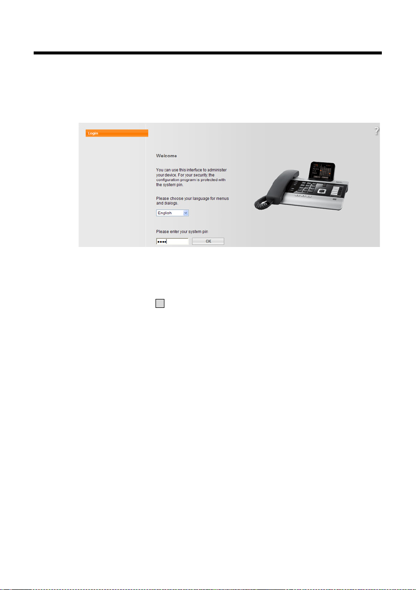
The Web configurator pages (Web pages) contain the UI elements shown in
Figure 2 (example).
Menu bar
10
Figure 2 Example of the structure of a Web configurator page
The Web configurator menus are displayed in the form of tab pages in the
menu bar.
The following menus are available:
Home
The home page opens once you have logged in to the Web configurator. It contains information on the Web configurator functions.
Settings
This menu allows you to make settings on your phone.
If you select the Settings menu, a list containing this menu's functions is dis-
played in the navigation area (
Status
This menu provides you with information about your phone.
¢ page 11).
Page 13
Log Off
V
‰
‰
.
You will find the Log Off function to the right of the menu bar on every Web
page.
Please note
For an overview of the Web configurator menu, see ¢ page 5.
Using the navigation area
The functions of the menu selected in the menu
bar are listed in the navigation area (
If you select a function, the associated page containing information and input fields opens in the
working area. The selected function is highlighted
in orange.
If a function is assigned subfunctions, these are
listed below the function as soon as you select the
function (for example Te le p ho ny ).
The relevant page for the first subfunction (highlighted in orange) is displayed in the working area.
Using the working area
Depending on the function selected in the navigation area, information or dialogue
boxes are displayed in the working area which allow you to make or change your
phone settings.
¢ page 10).
Making changes
Make settings via input fields, lists or options.
u There may be restrictions regarding the possible values for a field e.g., the max-
imum number of characters, entering special characters or certain value ranges.
u To open a list, click . You can choose between default values.
u There are two kinds of options:
– Checkboxes: You can select one or more options from a list. Active options
are indicated by , non-active options by . You can activate an option by
clicking . The status of the other options in the list does not change. You
can deactivate an option by clicking .
– Alternative options (radio buttons). The active option in the list is indicated
by , and the non-active by . You can activate an option by clicking .
The previously activated option is deactivated. You can only deactivate an
option by activating another option.
11
Page 14

Entering Cyrillic and Turkish characters
In the following section, the specified maximum number of characters permitted in
a field refers to Latin characters and digits (1 character = 1 byte), i.e., 1 character
means 1 byte.
Cyrillic and Turkish characters require 2 bytes each, e.g., with a field length of
16 characters, you can enter a maximum of 8 Cyrillic or Turkish characters.
If you enter too many characters into a field, the entry is rejected (not saved in the
base). The "old" field content (or the default settings) are retained and displayed
again when the Web page is updated. No warning/confirmation is given.
Applying changes
As soon as you have made your change on a page, activate the new setting on the
phone by selecting Set.
If your entry does not comply with the rules for this field, an appropriate error message is displayed. You can then repeat the input.
Warning
Changes that have not been saved on your phone are lost if you move to
another Web page or the connection to the Web configurator is lost e.g., due to
exceeding the time limit (
Using the buttons
Buttons are displayed in the bottom section of the working area. The following buttons are displayed depending on the function selected:
Edit
Display connection data in the Web browser so that they can be edited.
Browse
Select a file on the PC whose Web browser is linked to the Web configurator.
Update Firmware
Start a firmware update.
Delete
Delete a file/directory.
OK
Perform an operation (e.g., log in to the Web configurator, delete connection).
Cancel
Reject changes made on the Web page and reload the settings that are currently
saved in your phone to the Web page.
Restore
Load phone data (device settings) stored on the PC back on to the phone.
Set
Store changes made on a Web page on the phone.
Save
Save data that determines the settings/configuration of the base or a phone
entry in a file on the PC.
¢ page 9).
12
Page 15

Tra nsf er
Transfer the base's directory to the PC and store it there.
Delete Connection
Delete a connection from the phone's configuration.
<Add
Transfers an available object highlighted in the list to the list of selected objects.
Remove >
Removes a highlighted object from the list of selected objects.
Up
Moves a highlighted list element one space up.
Down
Moves a highlighted list element one space down.
Select VoIP Provider
Starts the Wizard, which helps you download the general configuration data of
your VoIP provider from the Internet.
Next>
In a multiple-step dialog (Wizard), closes the current step, and moves to the next
step.
<Back
In a multiple-step dialog, cancels the current step, and moves one step back so
that you can repeat the step.
Finish
Close the multiple-step dialog (Wizard). Apply the changes.
Opening Web pages
A brief outline of how to navigate to the individual Web configurator functions is
given below.
Example
Defining dialling plans:
Settings ¢Te l ep ho n y ¢ Dialling Plans
To open the Web page, proceed as follows after registration:
¤ Select the Settings menu in the menu bar.
¤ Click the Te le ph o ny function in the navigation area.
The Te le p ho ny subfunctions are displayed in the navigation tree.
¤ Select the Dialling Plans subfunction.
13
Page 16

IP Configuration – Connecting to the LAN
Assigning the IP address
Select the necessary settings for operating your phone in your local network and
for connecting it to the Internet, if necessary. For more detailed explanations of the
individual components/terms, see the glossary in the user guide for the phone.
¤ Open the Settings ¢ IP Configuration Web page.
Address Assignment area
Specify the base's address in the LAN.
IP address type
Select Obtained automatically, if you want your phone to be assigned a
dynamic IP address by a DHCP server in your local network. No further settings
are needed. The following fields in this section are greyed out and deactivated.
Select Static if you would like to set up a static local IP address for your phone.
A static IP address is useful, for example, if port forwarding or a DMZ is set up on
the router for the phone. The phone often requires a static IP address, e.g., if you
connect the phone directly to the PC.
The following fields are only activated if you select IP address type = Static:
IP address
Enter an IP address for your phone. This IP address allows your phone to be
reached by other parties in your local network (e.g., PC).
192.168.2.2 is the default.
Please note:
– The IP address must be from the address block reserved for private use on the
router. This is generally in the range 192.168.0.1 – 192.168.255.254 with
Subnet mask 255.255.255.0. The subnet mask determines that the first three
parts of the IP address must be identical for all subscribers in your LAN.
– The static IP address must not belong to the address block (IP pool range)
that is reserved for the router's DHCP server. It must also not be used by
another device on the router.
If necessary, check the settings on the router.
Subnet mask
Enter the subnet mask for your device's IP address. For addresses from the
address block 192.168.0.1 – 192.168.255.254, the subnet mask 255.255.255.0 is
generally used. This is preconfigured when the phone is supplied.
Default Gateway
Enter the IP address for the standard gateway through which the local network
is connected to the Internet. This is generally the local (private) IP address for
your router (e.g., 192.168.2.1). Your phone requires this information to be able to
access the Internet.
192.168.2.1 is the default.
14
Page 17

Preferred DNS server
Enter the IP address for the preferred DNS server. DNS (Domain Name System)
allows you to assign public IP addresses to symbolic names. The DNS server is
required to convert the DNS name into the IP address when a connection is
being established to a server.
You can specify your router's IP address here. The router forwards phone address
requests to its DNS server.
192.168.2.1 is the default.
Alternate DNS server (optional)
Enter the IP address for the alternate DNS server that should be used in situations where the preferred DNS server cannot be reached.
¤ Select Set to save the changes.
Or
¤ Select Cancel to reject the changes.
After you have changed the IP configuration, the base is rebooted. You are logged
off the Web configurator. The Login Web page is displayed after the reboot.
Allowing access from other networks
The default setting for your phone only allows you to access your phone's Web configurator via a PC that is in the same local network as your phone. The subnet mask
of the PC must match that of the phone.
You can also allow access from PCs in other networks.
Warning
Authorising access from other networks increases the risk of unauthorised
access. It is therefore recommended that you deactivate remote access if you no
longer require it.
¤ Open the Settings ¢ IP Configuration Web page.
Remote Management area
¤ Select Yes to authorise access from other networks.
To deactivate remote access, select No. Access is then limited to PCs in your own
local network.
¤ Enter a name for your base station in the Device Name in the Network field up
to 75 characters). The phone can be addressed with this name within the local
network.
Access to the Web configurator services from other networks is only possible if your
router is set accordingly. The router must pass on the service requests from "outside" to Port 80 (default port) of the phone. Be sure to read the user guide for your
router.
To establish a connection, the public IP address or the DNS name of the router and,
where applicable, the port number on the router must be indicated in the Web
browser of the remote PC.
15
Page 18

Entering an HTTP proxy server (only when connected to an internal company network)
Direct connections between network subscribers and the Internet are often not
permitted within internal company or organisation networks (Intranet). In such
cases, all HTTP calls from the network are "transferred" by a proxy server. The proxy
server is a computer or program within the network.
If your phone is connected to such a network, you must store the address of this
HTTP proxy server on the phone and activate handling of HTTP calls via the HTTP
proxy server.
Only then will you be able to access the online directory or display weather information etc. (information services).
¤ Open the Settings ¢ IP Configuration Web page.
HTTP proxy area
Enable proxy
Select Yes if your phone is to handle HTTP calls via your network's HTTP proxy
server.
If you select No, the phone will attempt to access the Internet directly.
Proxy server address
Enter the URL of the proxy server to which your phone is to send HTTP calls.
The proxy server then creates the connection to the Internet.
Proxy server port
Enter the communication port used on the HT TP proxy server (number between
0 and 55,000). It is mainly port 80 that is used.
¤ Select Set to save your settings.
16
Page 19
Telephony – Connections:
Configuring phone connections
Open the Settings ¢ Te l ep ho n y ¢ Connections Web page for a list with all possible connections (phone numbers) that you can configure or are already available
for your base.
You can use this list to configure and manage the connections of your base.
This list is divided into the following areas:
u Fixed Line Connection
Prerequisite: Your base is (or was last) connected with the analogue fixed line
network.
You do not have to configure the fixed line network connection. You can make
or receive calls on the fixed line network connection once your telephone is connected to the fixed line network.
You can also change the settings for the fixed line network connection
¢ page 20).
(
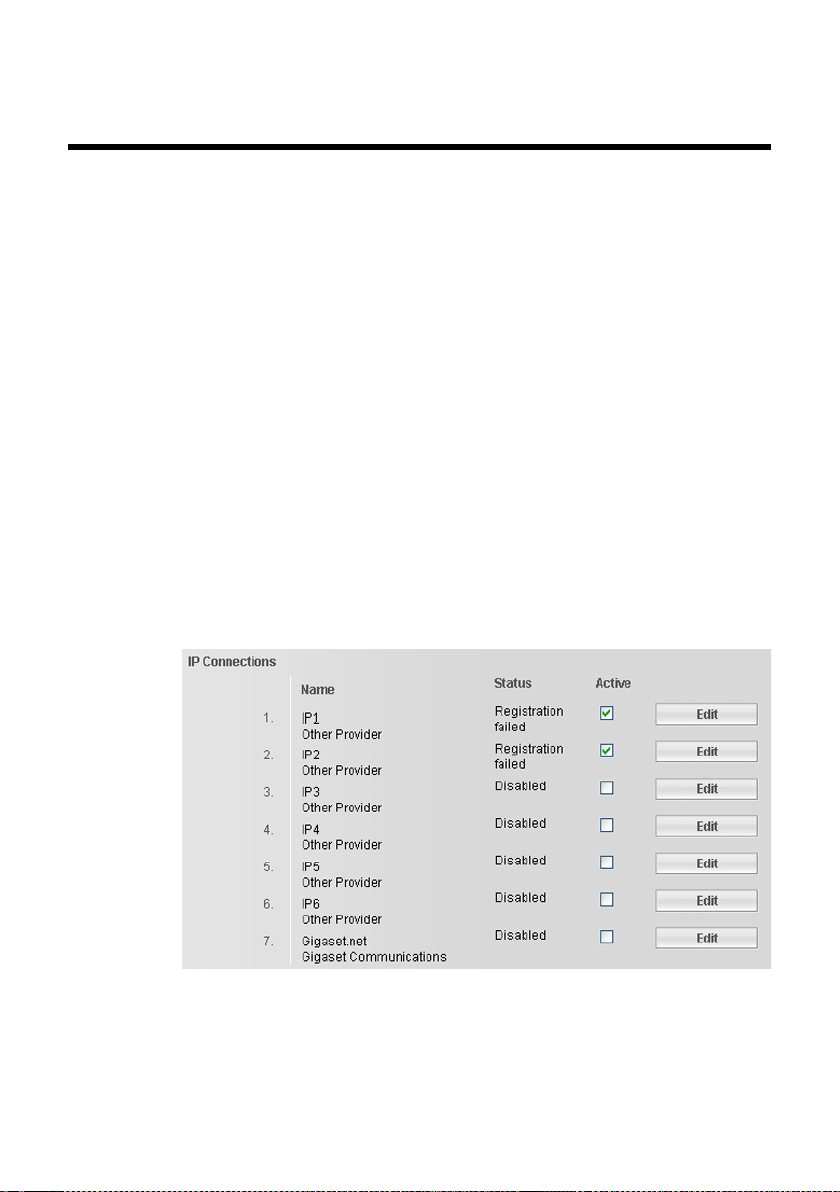
u IP Connection
You can assign up to six VoIP connections (VoIP phone numbers) to your base.
You need to set up a VoIP account with a VoIP provider for each VoIP phone
number. You must save the access data for each account and for the relevant
VoIP provider in the phone.
A list entry is available for each VoIP connection (
configure and manage the connection (
¢ Figure 3) which is used to
¢ page 22).
Figure 3 List of possible VoIP connections
u Gigaset.net
Your phone is preassigned with a Gigaset.net phone number. The Gigaset.net
connection is ready to use once the base is connected to the internet. In
Gigaset.net, you can call other Gigaset.net subscribers free of charge. Further
17
Page 20
information about Gigaset.net can be found in the long user guide for the phone
on the enclosed CD.
To find out which settings are possible for Gigaset.net, see ¢ page 29.
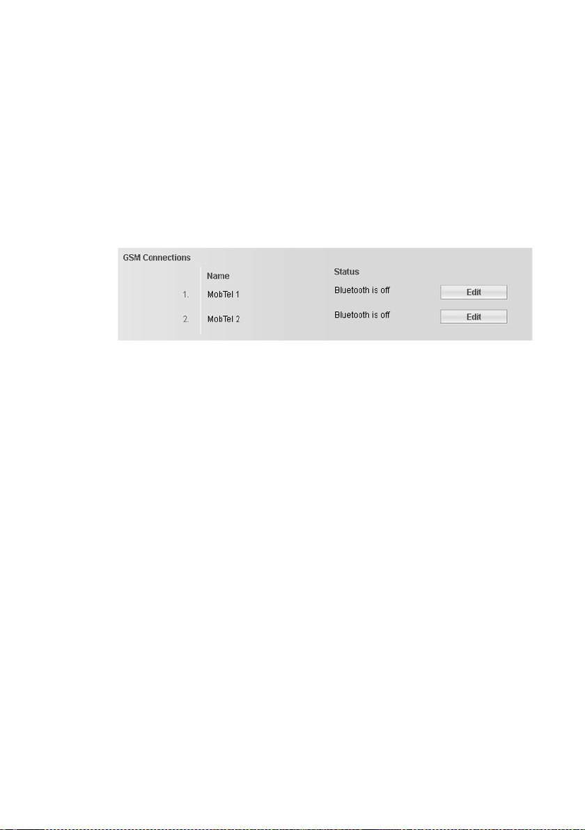
u GSM Connections
You can also make calls on your base and/or a registered handset via the GSM
connection of your Bluetooth GSM mobile phone (call external parties via the
GSM connection of the mobile phone or receive calls to the GSM connection).
To do this, you can register up to five mobile telephones (i.e., save in the Known
Devices list), which you can connect in alternation with your base.
The Known Devices list can only be edited on the base. Further information can
be found in the long user guide for the phone on the CD.
Figure 4 List of GSM connections
The list of connections contains the following information:
Name
The name that you have specified for the connection is displayed, otherwise the
default name is shown (IP1 up to IP6 for VoIP connections, Fixed Line for the
fixed line network connection, and Gigaset.net).
For GSM connections, the Bluetooth name is displayed under which the corresponding mobile phone is stored in the list of "Known Devices" on the base.
You can change this name. Thereto select the Edit button next to the GSM connection and enter a name of up to 16 characters.
For VoIP connections, the name of the network provider is also displayed. If the
name is unknown, the display will show Other Provider.
18
Page 21

Status
Indicates the status of the connection.
Possible values for VoIP connections and the Gigaset.net connection are:
Registered
The connection is activated. The phone has been successfully registered. You
can use the connection to make calls.
Disabled
The connection is deactivated. The phone is not registering with the corre-
sponding account with the VoIP service. You cannot use the connection to make
or receive calls.
Registration failed / Server not accessible
Your phone was unable to register with the VoIP service, e.g., because the VoIP
access data is incorrect or incomplete or the phone is not connected to the Internet. Further information can be found in the long user guide for the base on the
enclosed CD.
Possible values for the fixed line network connection are:
Connected
The phone is connected to the fixed line network.
Possible values for the GSM connections are:
Registered
Bluetooth is activated on the base . The mobile phone is registered to the base,
i.e. it appears in the Known Devices list. However, the mobile phone is not yet
activated. The Connect Cell Phone option is not set for this mobile phone. No
calls can be made from the base via the corresponding GSM connection.
Active
The mobile phone is displayed in the Known Devices list and is active. The
Connect Cell Phone option is set for this mobile phone.
Bluetooth is off
Bluetooth is deactivated on the base.
19
Page 22

Active (only for VoIP connections and Gigaset.net connection)
You can use the option in the Active column to activate ( ) and deactivate ( )
VoIP connections. If a connection is deactivated, the phone will not register for
this connection. The connection can be activated/deactivated by clicking
directly on the option. The change does not need to be saved.
To configure a connection or to change the configuration of a connection:
¤ Select the Edit button next to the connection.
Setting the fixed line network connection
¤ Open the Settings ¢ Te le ph o ny ¢ Connections Web page.
¤ Select Edit in the Fixed Line Connection area.
Connection Name or Number
You can define a name for your telephone connection, which replaces the
default name Fixed Line in displays or lists. Enter a name of up to 16 characters
or the phone number of your fixed line network connection.
Dialling mode
The following dialling modes can be selected:
Pulse dial
Pulse dialling mode (PD) is used only for a few old PABXs.
DTMF
Tone dialling (DTMF) is now the most common dialling mode.
Recall
Your phone comes preset with a flash for general operation of the phone on the
main connection. The flash specifies the duration of the line interruption used to
send control signals to the exchange or the telecommunications system (transfer (ECT), setting up a consultation call, etc.). For operation on a PABX, you may
have to change this value. Please refer to the user guide for your PABX.
Select the required flash from the list.
¤ Select Set to save your settings.
Or:
¤ Click the Cancel button to reject the changes you have made.
This returns you to the list of connections.
20
Page 23

Configuring the Gigaset.net connection
‰
¤ Open the Settings ¢ Te le ph o ny ¢ Connections Web page.
¤ Select Edit in the Gigaset.net area.
Connection Name
Enter a name for the Gigaset.net connection (max. 16 characters). This name is
displayed on the base e.g., in the lists for receive/send connections and in the
call lists as receive connection (number that the caller dialled).
If you do not enter a name, the default name Gigaset.net is used.
STUN enabled
The Gigaset.net connection is preconfigured in your phone. The Gigaset.net
uses a STUN server as standard. In the sent data packets, Gigaset.net replaces the
private IP address of your phone with its public IP address.
If you operate your phone behind a router with symmetrical NAT, STUN cannot
be used. Otherwise, when making Gigaset.net calls you will not be able to hear
the caller.
In this case, deactivate STUN for the Gigaset.net connection.
¤ Select No to deactivate STUN.
¤ Select Yes if you want your phone to use STUN.
¤ Select Set to save the changes.
Or:
¤ Click the Cancel button to reject the changes you have made.
This returns you to the list of connections.
Activating/deactivating the Gigaset.net connection
¤ In the list of connections in the Gigaset.net area: Use the option in the Active
column to activate ( ) or deactivate ( ) the Gigaset.net connection.
Please note
If you do not use your Gigaset.net connection for six months, it is automatically
deactivated. You cannot be reached for calls from Gigaset.net.
The connection is reactivated:
u As soon as you start a search in the Gigaset.net directory
u make a call via Gigaset.net, i.e., dial a number ending in #9 (two attempts
may be necessary) or
u activate the connection via the Web configurator as described above.
21
Page 24

Configuring the VoIP connection
¤ Open the Settings ¢ Te le ph o ny ¢ Connections Web page.
¤ Select the Edit button next to the VoIP connection that you want to configure or
the configuration you wish to change.
This will open a Web page where you can make the settings that your phone needs
to access your provider's VoIP server.
The Web page always displays the following areas:
u IP Connection (¢ page 22),
u Auto Configuration (¢ page 22)
u Profile Download (¢ page 23)
u Personal Provider Data (¢ page 24).
The areas
u General data of your service provider and (¢ page 25)
u Network data for your service provider (¢ page 26)
can be shown and hidden by selecting the Show Advanced Settings and Hide
Advanced Settings buttons.
You must enter the VoIP provider's general access data in these areas. You can
download this data from the Internet for several VoIP providers (
load area", page 23).
¤ Make the settings on the Web page.
¤ Save them in the phone (¢ page 28).
¤ Activate the connection if necessary (¢ page 28).
¢ "Profile Down-
22
IP Connection area
Connection Name or Number
Enter a name for the VoIP connection or the VoIP phone number (max.
16 characters). This name is used to display the connection on the base and in
the Web configurator interface, for example when assigning the receive and
send connections and for call display.
Auto Configuration area
The entire configuration process for a VoIP connection is automated for some VoIP
providers. You can download the necessary VoIP access data to your phone from
the Internet.
Prerequisites:
u You have rece ive d an auto configuration code from your VoIP provider.
u The general access data for your VoIP provider is available for downloading.
You can download all the data required for VoIP access from the Internet:
¤ Enter the auto configuration code you received from your VoIP provider in the
Auto Configuration area in the Auto Configuration Code field (maximum
32 characters).
¤ Select the Start Auto Configuration button.
Page 25

The telephone establishes a connection to the Internet and downloads all data
required for the VoIP connection, i.e., the general provider information and your
personal provider data (account data) are saved to your base.
If you have already entered details on the Web page, this is deleted as soon as Start
Auto Configuration is selected. The fields in the Personal Provider Data and General data of your service provider areas and the server addresses in the Network
data for your service provider area are overwritten by the downloaded data.
Generally, you should not have to enter any additional data on this Web page.
Please note
If the message Download of settings not possible! File is corrupt! appears, no
data will be loaded onto the phone. Possible causes of this are:
u The incorrect code has been entered (e.g., upper/lower case rules have not
been followed). If necessary, enter the code again.
u The file that has been downloaded is invalid. Please consult your VoIP
provider.
When the download is complete, the Connections list will be displayed.
¤ Activate the connection as described on page 28.
You can then be reached on the corresponding VoIP phone number.
Profile Download area
Prerequisite: You must have received account data from your VoIP provider
(e.g., Authentication name, Authentication password).
Profile files of the most important VoIP providers are available to download on the
Gigaset configuration server. The address for the server is stored in your phone
¢ page 63).
(
To load the data onto your telephone, proceed as follows:
¤ Select Select VoIP Provider in the Profile Download area. This will display infor-
mation on the download procedure.
Please note
If you select the Select VoIP Provider button, any changes that have been made
to the Web page will be saved and checked. Values may need to be corrected
before the Select VoIP Provider operation is started.
The download procedure consists of several steps:
¤ Select the Next button.
¤ From the list, select the country for which the list of VoIP providers is to be
loaded.
¤ Select the Next button.
¤ Select your VoIP provider from the list.
If your provider is not included in the list, select Other Provider. In this case you
will have to enter the general provider data by hand (see "General data of your
service provider area" and "Area: Network data for your service provider"
below).
23
Page 26

¤ Select the Finish button.
Please note
If only one country is available, the country list will not be displayed. The list of
provider is then displayed immediately.
The details of the selected provider are loaded to your phone and displayed under
General data of your service provider (¢ page 25) and Network data for your
service provider (
these areas.
The Provider field shows the name of the VoIP provider selected or the Other Pro-
vider. A link to the provider's homepage is displayed where available.
In the Profile Version field the version of the currently loaded profile is displayed.
To complete configuration of your VoIP connection, enter your account data in the
Personal Provider Data area.
Please note
After the first download of the VoIP provider settings, your phone will check
whether a newer version of the file for your VoIP provider is available from the
Internet each day on the configuration server (
Personal Provider Data area
Enter the configuration data that is required to access your VoIP provider's SIP
service. This data can be obtained from your VoIP provider.
The field names (Authentication name etc.) of this area listed below are default
names and may change. If you have already downloaded the provider's general
details ("Select VoIP Provider" button, see above), field entries will be replaced by
provider-specific names to facilitate orientation (e.g., SIP-ID instead of
Authentication name).
Authentication name
Specify the registration or authentication ID agreed with your VoIP provider
(maximum 32 digits). The registration ID serves as the access ID that your phone
must specify when registering with the SIP proxy/registrar server. The
Authentication name is usually identical to the Username, i.e., to your Internet
phone number.
Authentication password
Enter the password that you have agreed with your VoIP provider in the
Authentication password field (maximum 32 characters). The phone needs the
password when registering with the SIP proxy/registrar server.
Username
Enter the caller ID for your VoIP provider account (maximum 75 characters).
This ID is usually identical to the first part of your SIP address (URI, your Internet
phone number).
¢ page 26). You do not have to make any further entries in
¢ page 65).
24
Page 27

Example
Example: If your SIP address is "987654321@provider.com", enter
"987654321" as the Username.
Display name (optional)
Enter any name that should be shown in the other caller's display when you call
them via the Internet (example: Anna Sand). All characters in the UTF8 character
set (Unicode) are permitted. The name must not exceed 32 characters.
If you do not enter a name, your Username or your VoIP phone number will be
displayed.
Ask your VoIP provider if this feature is supported.
General data of your service provider area
If you have downloaded the general settings for the VoIP provider from the configuration server (
from the download. Generally speaking, you do not need to configure any settings
in this area.
Domain
Specify the last part of your SIP address (URI) here (maximum 74 characters).
For the SIP address "987654321@provider.com", enter "provider.com" in
Domain.
Proxy server address
The SIP proxy is your VoIP provider's gateway server. Enter the IP address or the
(fully-qualified) DNS name of your SIP proxy server (maximum 74 characters).
Example: myprovider.com.
Proxy server port
Enter the number of the communication port that the SIP proxy uses to send
and receive signalling data (SIP port).
Port 5060 is used by most VoIP providers.
Registration server
Enter the (fully-qualified) DNS name or the IP address of the registrar server
(maximum 74 characters).
The registrar is needed when the phone is registered. It assigns the public IP
address/port number that were used by the phone on registration to your SIP
address (Username@Domain). With most VoIP providers, the registrar server is
identical to the SIP server. Example: reg.myprovider.com.
Registration server port
Enter the communication port used on the registrar. Port 5060 is used in most
cases.
Registration refresh time
Enter the time intervals (in seconds) at which the phone should repeat the
registration with the VoIP server (SIP proxy) (a request will be sent to establish a
session). The repeat is required so that the phone's entry in the tables of the SIP
¢ page 23), then the fields in this area will be preset with the data
Example
25
Page 28

proxy is retained and the phone can therefore be reached. The repeat will be carried out for all activated VoIP connections.
The default is 180 seconds.
If you enter 0 seconds, the registration will not be repeated periodically.
Area: Network data for your service provider
Please note
If you have downloaded the general settings for your VoIP provider from the
Gigaset configuration server (
preset with the data from the download (e.g., the settings for the STUN server
and outbound proxy).
If your phone is connected to a router with NAT (Network Address Translation) and/
or a firewall, you must select some settings in this area so that your phone can be
reached from the Internet (i.e., can be addressed).
Through NAT, the IP addresses of subscribers in the LAN are concealed behind the
public IP address of the router.
For incoming calls
If port forwarding is activated or a DMZ is set up for the phone on the router, no special settings are required for incoming calls.
If this is not the case, an entry in the NAT routing table (in the router) is necessary in
order for the phone to be reached. This entry is created when the phone is registered with the SIP service. In the interest of security, this entry is automatically
deleted at certain intervals (session timeout). The phone must therefore confirm its
registration at certain intervals (
stays in the routing table.
For outgoing calls
The phone needs its public address in order to receive caller voice data.
There are two possibilities:
u The phone requests the public address from a STUN server on the Internet (Sim-
ple Transversal of UDP over NAT). STUN can only be used with asymmetric NATs
and non-blocking firewalls.
u The phone does not direct the connection request to the SIP proxy but to an out-
bound proxy on the Internet that supplies the data packets with the public
address.
The STUN server and outbound proxy are used alternately to work around the NAT/
firewall in the router.
STUN enabled
Select Yes if you want your phone to use STUN as soon as it is used on a router
with asymmetric NAT.
STUN server address
Enter the (fully-qualified) DNS name or the IP address of the STUN server on the
Internet (maximum 74 characters).
¢ page 23), then some fields in this area will be
£ NAT refresh time on page 27) so that the entry
26
Page 29

If you selected the Ye s option in the STUN enabled field, you must enter a STUN
server.
STUN server port
Enter the number of the communication port on the STUN server. The default
port is 3478.
STUN refresh time
Enter the time intervals at which the phone should repeat the registration with
the STUN server. The repeat is required so that the entry of the phone in the
tables of the STUN server is retained. The repeat will be carried out for all activated VoIP connections.
Ask your VoIP provider for the STUN refresh time.
The default is 240 seconds.
If you enter 0 seconds, the registration will not be repeated periodically.
NAT refresh time
Specify the intervals at which you want the phone to update its entry in the NAT
routing table. Specify an interval in seconds that is a little shorter than the NAT
session timeout.
As a rule you should not need to change the preconfigured value for the NAT
refresh time.
Outbound proxy mode
Specify when the outbound proxy should be used.
Always
All signalling and voice data sent by the phone is sent to the outbound proxy.
Automatic
Data sent by the phone is only sent to the outbound proxy when the phone is
connected to a router with symmetric NAT or a blocking firewall. If the phone is
behind an asymmetric NAT, the STUN server is used.
If you have set STUN enabled = No or have not entered a STUN server, the outbound proxy is always used.
Never
The outbound proxy is not used.
If you do not make an entry in the Outbound server address field, the phone
behaves independently of the selected mode, as with Never.
Outbound server address
Enter the (fully qualified) DNS name or the IP address of your provider's outbound proxy (maximum 74 characters).
Please note
With many providers, the outbound proxy is identical to the SIP proxy.
Outbound proxy port
Enter the number of the communication port used by the outbound proxy.
The default port is 5060.
27
Page 30

Saving settings on the phone
‰
¤ Select Set to save the changes.
The Connections list is displayed after saving.
Or:
¤ Click the Cancel button to reject the changes you have made.
Or:
¤ Click the Delete Connection button to delete the VoIP connection from the con-
figuration. You can no longer be contacted via this phone number or make calls
via this connection.
If the connection you have deleted was the send connection of an internal subscriber then a new send connection will automatically be assigned to this internal subscriber. This is the fixed line network number if the phone is connected
to the analogue fixed line network.
Please note
If you do not make any entries for a prolonged period, the connection to the
Web configurator is automatically terminated. Unsaved entries are lost. If necessary, save entries as you go along. You can subsequently continue the entry and
make changes if necessary.
Activating a new VoIP connection
If you have configured a new VoIP connection, you must also activate it.
In the Connections list:
¤ Activate the relevant option in the Active column ( = activated).
Your phone will register itself with the VoIP provider using the relevant access data.
Refresh the Web page (e.g., by pressing F5).
The Status Registered column will appear if registration was successful. You can
now be reached on this VoIP phone number.
After making a new entry, the VoIP connection is assigned as a receive connection
to the base, all registered handsets, the answering machine AM 1, and the fax
machine, if connected.
You can change the assignment (
¢ page 34).
28
Page 31

Configuring a GSM connection
¤ Open the Settings ¢ Te le ph o ny ¢ Connections Web page.
¤ Select the Edit button next to the GSM connection that you want to configure.
Connection Name or Number
Enter the number of the mobile phone or define a name for the GSM connection
(max. 16 characters). This name is displayed on the base e.g., in the Known
Devices list, in the lists for receive/send connections and in the call lists as
receive connection (number that the caller dialled).
¤ Select Set to save the changes.
Or:
¤ Click the Cancel button to reject the changes you have made.
This returns you to the list of connections.
Or:
¤ Click the Delete Connection button to delete the GSM connection from the con-
figuration. You can no longer be contacted via this phone number or make calls
via this connection.
If the connection you have deleted was the send connection of an internal subscriber then a new send connection will automatically be assigned to this internal subscriber. This is the fixed line network number if the phone is connected
to the analogue fixed line network.
29
Page 32

Telephony – Audio:
Optimising voice quality for VoIP connections
You can make general and connection-specific settings to improve the voice quality for VoIP telephony.
¤ Open the Settings ¢ Te le ph o ny ¢ Audio Web page.
The voice quality for VoIP connections is mainly determined by the voice codec
used for transferring the data and the available bandwidth of your DSL connection.
In the case of the voice codec, the voice data is digitalised (coded/decoded) and
compressed. A "better" codec (better voice quality) means more data needs to be
transferred, i.e., perfect voice data transfer requires a DSL connection with a larger
bandwidth.
The following voice codecs are supported by your phone:
G.722
Excellent voice quality. The broadband speech codec G.722 works at the same
bit rate as G.711 (64 kbit/s per speech connection) but with a higher sampling
rate. This allows higher frequencies to be played back. The speech tone is therefore clearer and better than for the other codecs (High Definition Sound Performance).
Other HDSP compatible handsets include: Gigaset S67H, S68H, SL37H.
G.711 a law / G.711 μ law
Excellent voice quality (comparable with ISDN). The necessary bandwidth is
64 kbit/s per voice connection.
G.726
Good voice quality (inferior to that with G.711 but better than with G.729).
Your phone supports G.726 with a transmission rate of 32 kbit/s per voice con-
nection.
G.729
Average voice quality. The necessary bandwidth is less than or equal to 8 kbit/s
per voice connection.
Both parties involved in a phone connection (caller/sender and recipient) must use
the same voice codec. The voice codec is negotiated between the sender and the
recipient when establishing a connection.
You can influence the voice quality by selecting (bearing in mind the bandwidth of
your DSL connection) the voice codecs your phone is to use, and specifying the
order in which the codecs are to be suggested when a VoIP connection is established.
30
Page 33

Settings for Bandwidth area
The settings in this area affect all VoIP connections.
Allow 1 VoIP call only
You can usually make up to four VoIP calls at the same time on your phone. If,
however, your DSL connection has a narrow bandwidth, there may be problems
if multiple VoIP calls are made at the same time. The data is no longer transferred
properly (long voice delay, data losses etc.).
¤ Select Yes after Allow 1 VoIP call only to prevent any further parallel VoIP
phone connections being established.
¤ If you wish to permit multiple parallel VoIP connections, select No.
Please note
If only one VoIP connection is permitted, the following VoIP network services
will no longer be available:
u Call waiting
Call waiting is not displayed during a call via VoIP.
u External consultation call from a VoIP call
u Call swapping and initiating a conference call via VoIP
Voice Quality
Default settings for the codecs used are stored in your phone: one setting optimised for low bandwidths and one for high bandwidths.
¤ Activate one of the options Optimized for low bandwidth / Optimized for
high bandwidth if you wish to accept a default setting for all VoIP connec-
tions. The settings are shown in the Settings for Connections area and can-
not be changed.
¤ Activate the Own Codec preference option if you wish to select and set con-
nection-specific voice codecs yourself (see "Settings for Connections area").
Settings for Connections area
In this area you can make specific settings for each of your VoIP connections.
You can make the following settings for each VoIP connection configured on your
phone:
Volume for VoIP Calls
Depending on the VoIP provider, it is possible that the received voice/earpiece
volume is too low or too high, so that adjusting the volume via the handset is not
adequate.
Specify whether the received volume range is too high or too low. The following
options are available:
Low
Voice/earpiece volume is too high. Activate this option to reduce the volume by
6 dB.
Normal
The voice/earpiece volume does not need to be raised/lowered.
31
Page 34

High
Voice/earpiece volume is too low. Activate this option to increase the volume by
6 dB.
Selected codecs / Available codecs
Prerequisite: The Own Codec preference option is activated for the Voice Quality in the Settings for Bandwidth area.
In the Selected codecs and Available codecs lists, you can define your own
codec preference tailored to your DSL connection.
Select the voice codecs your phone is to use, and specify the order in which the
codecs are to be suggested when a VoIP connection is established via this VoIP
connection.
¤ Apply the voice codecs that your phone is to suggest for outgoing calls into
the Selected codecs list.
To do this, in th e Availabl e codec s list select the voice codec that you want to
apply (you can mark several entries using the Shift key or the Ctrl key). Select
<Add.
¤ Move the voice codecs that you do not want the phone to use into the
Available codecs list.
Select the voice codecs in the Selected codecs list (see above) and click the
Remove> button.
¤ Sort the voice codecs in the Selected codecs list into the order in which they
should be suggested to the receiving device when a connection is established. To do this, use the Up and Down buttons.
When establishing a VoIP connection, the phone suggests the first voice codec
in the Selected codecs list to the receiving device to begin with. If the receiving
device does not accept the codec (e.g., because it is not supported), the second
voice codec on the list is suggested etc.
If the receiving device does not accept any of the voice codecs in the Selected
codecs list, the connection is not established. An appropriate message will be
displayed on the handset.
If the phone always starts by trying to establish a broadband connection, put
the G.722 codec at the top of the Selected codecs list.
32
Please note
u Only deactivate codecs (put them in the Available codecs list) if there is a
particular reason. The more codecs that are deactivated, the greater the
risk that calls cannot be established due to unsuccessful codec negotiations. In particular you can only establish broadband connections if you
permit the G.722 codec.
u With incoming calls, all supported voice codecs are always permitted.
Page 35

Settings for Codecs area
To save additional bandwidth and transmission capacity, on VoIP connections that
use the G.729 codec you can suppress the transmission of voice packets in pauses
("Silence Suppression"). Then, instead of the background noises in your environment, your caller hears a synthetic noise generated in the receiver.
Please note: "Silence Suppression" can sometimes lead to a deterioration in the
voice quality.
¤ In the Enable Annex B for codec G.729 field, state whether the transmission of
data packets during pauses should be suppressed when using the G.729 codec,
(select Ye s ).
Saving settings on the phone
¤ Select Set to save the settings for the voice quality.
If you have changed the setting for Enable Annex B for codec G.729 in the Settings
for Codecs area, the base must be restarted. You are logged off the Web configura-
tor. The Login Web page is displayed after the reboot.
Please note
Observe the following for good voice quality:
u When making calls using VoIP, avoid performing other Internet activities
(e.g., surfing the Internet).
u Please note that voice delays can occur depending on the codec used and
the network capacity utilisation.
Voice quality and infrastructure
Using your Gigaset, you can make calls with good voice quality via VoIP.
However, your phone's performance with VoIP – and therefore the voice quality –
also depends on the properties of the entire infrastructure.
The following components from your VoIP provider may impact performance:
u Router
u DSLAM
u DSL transmission line and speed
u Connection paths over the Internet
u If applicable, other applications that also use the DSL connection
In VoIP networks, voice quality is affected by various things including the "quality
of service" (QoS). If the entire infrastructure has QoS, voice quality is higher (fewer
delays, less echoing, less crackling etc.).
If, for example, the router does not have QoS, then the voice quality is not as good.
Please see the specialist documentation for further information.
33
Page 36

Telephony – Number Assignment:
Assigning send and receive connections
You can specify which phone connection is assigned as receive and/or send connections to the base and any connected device.
Please note
The following connections are assigned to the base and connected devices if
you do not assign any of the connections:
u Receive connections of the base and the registered handsets: All connec-
tions of the phone (fixed line network, Gigaset.net and VoIP) and the GSM
connection of your mobile phone providing it is registered and activated via
Bluetooth (connected; GSM).
u Send connections of the base and the registered handsets: The analogue
fixed line network connection that you entered first in the phone configuration.
u All connections (including of the GSM connection of a mobile phone con-
nected via Bluetooth) are assigned to the first answering machine as receive
connections. The other two answering machines are not assigned receive
connections.
u If the fax connection is active (see the user manual for the base on the
enclosed CD), all connections (including of the GSM connection of a mobile
phone connected via Bluetooth) are also assigned to the fax machine as
receive connections. The analogue fixed line network connection is assigned
to it as the send connection.
34
Page 37

Assigning receive/send connections to bases/handsets, changing internal names
You can assign as many of your connections as you wish to the base and all registered handsets. Receive connections determine which handset(s) will ring when a
call is received.
You can assign one of your connections as a send connection to the base and each
handset. The send connection specifies which phone number/VoIP account is
charged for calls from the base or handset. Exceptions: A dialling rule has been
defined for the dialled phone number (
You can also choose to select the send connection from the list of all available connections for each call made from the base/handset.
¢ page 43).
¤ Open the Settings ¢ Te le ph o ny ¢ Number Assignment Web page.
The following is displayed for the Desktop Phone and every handset (example):
The default name (INT 1, ... INT 7), any name you have set, and a list of connections
that are configured and active for the phone are displayed for each handset and the
base. The connection names are shown in the Connection column. The value GSM
is displayed for the GSM connection. The GSM connection is only displayed if the
list of known devices contains at least one GSM mobile phone.
¤ Change the internal name of the device in the Name field, if required.
¤ Define a connection as the send connection for each device. To do this, select
the option (radio button) following the connection in the for outgoing calls
column. The previous assignment will automatically be deactivated.
If you select the option Select line for each outgoing call instead, you can select
which connection is used to establish a connection every time you make a call.
35
Page 38

Please note
‰
The Gigaset.net number is fixed as the send connection for the base and each
registered handset. Numbers that end in #9 are automatically dialled via
Gigaset.net.
¤ For each device, select the connections that are to be assigned to the handset as
receive connections. To do so, click the option following the connection in the
for incoming calls column. Every handset can be assigned several or no connections ( = assigned).
¤ Select Set to save your settings.
Please note
u If the connection assigned to a device as a send connection is deleted, the
analogue fixed line network connection is automatically assigned to the
device as a send connection.
u If a connection is not assigned to a device as a receive connection, calls to
this phone number are signalled neither on the base nor any handset.
36
Page 39

Assigning receive/send connections to the FAX port
for outgoing calls for incoming calls
‰
Prerequisite: You must have activated the fax connection on the base.
You can assign as many of your connections as you like to the FAX port as receive
connections and one connection as a send connection. The device conntected to
the base via the FAX port is always assigned the internal name INT 8.
¤ Click the option after the connection in the first column (for outgoing calls),
which is to be assigned to the FAX port as a send connection. The previous
assignment will automatically be deactivated.
¤ Click the option after the connection in the second column (for incoming calls),
which is to be assigned to the FAX port as a receive connection. You can assign
several connections or no connection ( = assigned).
¤ Select Set to save your settings.
Please note
The settings are only effective if the FAX port on the base is activated
£ detailed user guide for the base available on the enclosed CD).
(
37
Page 40

Assigning receive connections to answering machines
For each of your connections, you can specify which of the three answering
machines on the base shall receive incoming calls. Simply assign each receive connection to an answering machine.
Please note
u Once the new entry is made, each connection is assigned to the integrated
answering machine 1 as a receive connection.
u An answering machine is not activated if it is not assigned a receive connec-
tion. It is not shown in the answering machine list and you cannot activate it.
¤ Open the Settings ¢ Te le ph o ny ¢ Number Assignment Web page.
The name of the corresponding Bluetooth mobile telephone is displayed in the list
of known devices for the GSM connection.
¤ In the Answering Machine area, for each connection (fixed line network, VoIP,
GSM), select the answering machine (AM 1, AM 2, AM 3), that you want to
receive calls for these connections (the answering machine must be activated).
You can assign as many connections as you wish to the answering machine.
If you select None for a connection, calls to this connection are not received by
the answering machine.
¤ Select Set to save your settings.
38
Page 41

Activating the fixed line network connection as an alternative connection
You can activate the fixed line network connection as an alternative connection on
your phone. If a call attempt fails via VoIP, an attempt is automatically made to
establish a connection via the analogue fixed line network.
An alternative connection would be used in the following instances:
u Your VoIP connections are busy
u The SIP server for the VoIP connection cannot be accessed
u The dialled VoIP connection has not yet been configured or has not been con-
figured correctly (e.g., incorrect password)
u The base does not have a connection to the Internet, for example because your
router is deactivated or not connected to the Internet.
¤ Open the Settings ¢ Te le ph o ny ¢ Number Assignment Web page.
Alternative Connection Area:
¤ To activate the fixed line network connection as an alternative connection, click
the option Ye s nex t to Automatic Fallback to Fixed Line. Select No to deactivate
the function.
¤ Then select Set to activate your settings.
39
Page 42

Telephony – Call Divert:
Activating Call Divert for VoIP connections
You can forward calls to your VoIP connections and to your Gigaset.net number.
You can forward calls to your VoIP connections to any external number (VoIP, fixed
line or mobile network number). The forwarding is done via VoIP.
You can forward calls to your Gigaset.net number within the Gigaset.net, i.e., to
another Gigaset.net number.
For each of your VoIP connections (VoIP accounts), you can determine if and when
calls to the corresponding VoIP number should be forwarded to a different VoIP
phone number.
You can also use the base or a registered handset to set call forwarding and
activate/deactivate it.
¤ Open the Settings ¢ Te le ph o ny ¢ Call Divert Web page.
The display shows a list of all your configured VoIP connections and your
Gigaset.net number.
Connections
Select the name you have assigned to the VoIP connection, or select
Gigaset.net.
When
Choose when you want an incoming call to be forwarded:
When busy
Calls are forwarded when the connection is occupied.
On no reply
Calls are diverted if no one accepts the call within several rings.
Always
Calls are diverted immediately, i.e. no more calls to this connection are signalled
on your base.
Off
Deactivate call forwarding
Call number
Enter the phone number to which the calls should be forwarded (maximum
32 characters, 0-9, *, #, R (recall), P (pause)). Please note that you may have to
enter the area code when forwarding to a fixed line network number in the same
area (depending on your VoIP provider and the setting for the automatic area
¢ page 41).
code
The settings only affect the phone number selected in Connections.
¤ Select Set to save your settings.
40
Please note
You can also use the base or a registered handset to set call forwarding for your
fixed line connection, and to activate/deactivate it.
Page 43

Telephony – Dialling Plans: Entering an access code
If your base is connected to a PABX, you may have to enter an access code for external calls (external prefixes e.g., "0"). You can save this access code on the base.
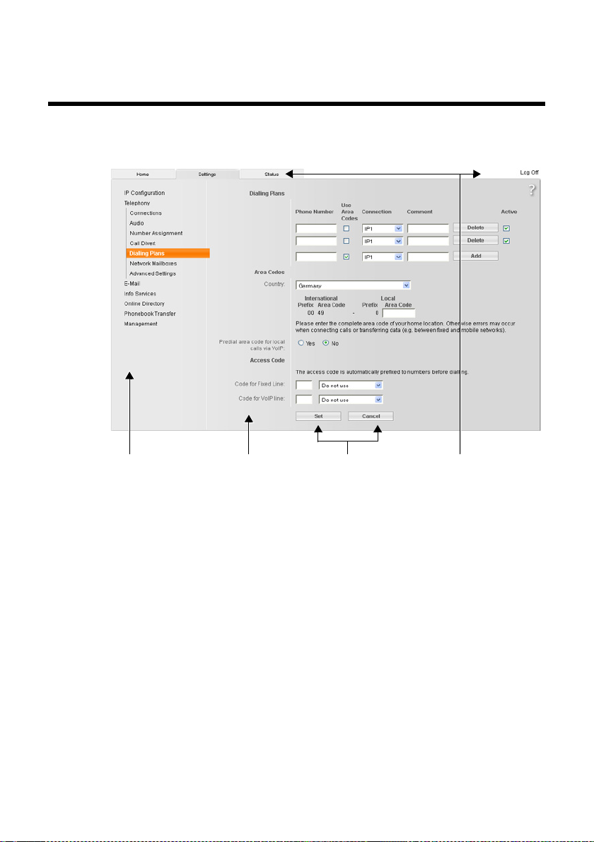
¤ Open the Settings ¢ Te le ph o ny ¢ Dialling Plans Web page.
In the Access Code area:
¤ In the Code for Fixed Line fields, enter the access code to be dialled in front of
phone numbers (maximum 3 figures) if you are calling via the fixed line network
connection.
¤ Select from the is added to numbers list for fixed line network calls if the phone
numbers should be prefixed by the access code.
Use for call lists
The access code prefixes numbers dialled on the base or handset selected from
a call list or an answering machine list.
Use always
The access code prefixes all numbers dialled on the base or a handset.
Do not use
The access code does not prefix any phone number before being dialled.
¤ In the Code for VoIP line field, enter the access code to be dialled in front of the
phone numbers (maximum 3 figures) if you are calling via a VoIP connection.
¤ Select from the is added to numbers list for VoIP calls when the phone numbers
should be prefixed by the access code. You can select from: Use for call lists, Use
always, Do not use (see above for the respective meanings).
¤ Select Set to save the settings.
Telephony – Dialling Plans:
Entering your own area code and extra codes
On the base, save the complete code (with international code) for the area in which
you are using the phone.
Please note the following for local calls:
u For local calls using your fixed line, you generally (depending on the exchange)
do not have to dial an area code. All the calls in the call list are saved with area
codes, for example. In order to be able to call a caller from the call list back, you
have to save the local area code in the phone for the area your phone is in (Local
area code). If your phone is in a "multiple area code" area, you also have to enter
the other area codes for this
u You have to dial the area code for local calls using your VoIP connection. If you
have saved your local area code in the phone and activated the Predial long distance access code for VoIP calls option, when numbers are dialled without a
local area code, the local area code that has been entered is included automatically (e.g., when dialling from the directory).
area as Extra area codes for PSTN connections.
41
Page 44

¤ Open the Settings ¢ Te le ph o ny ¢ Dialling Plans Web page.
In the Area Codes area:
¤ From the Country list, select the country in which you are using your phone.
Then, the international prefix (International Prefix and Area Code) and the prefix of the area code (Local Prefix Area Code) are set automatically.
¤ In the Local Area Code field, enter the area code for your town without a prefix
(maximum 8 figures 0–9, *, #, F (flash), P (pause)).
Activating/deactivating area code pre-dialling
¤ Select Yes behindPredial long distance access code for VoIP calls to activate
area code pre-dialling.
Select No to deactivate the function. You will then need to enter the area code
for local calls made via VoIP. Numbers in the directory must always contain the
area code when dialling via VoIP.
Please note
u The area code will also be prefixed to VoIP calls made to emergency num-
bers if there are no defined dialling plans for these numbers.
u The numbers of your network mailbox saved in the base are not prefixed
with a code (
Extra area codes for PSTN connections
¢ page 46).
¤ Enter the extra codes of your area in the fields Entry No. 1 up to Entry No. 5. Max-
imum 3 characters, digits and the characters "*", "#" are permitted for each extra
code.
42
Save settings
¤ Click on Set to save your settings.
Page 45

Telephony – Dialling Plans:
Defining dialling plans – cost control
You can define dialling plans to reduce costs:
u You can define a specific connection (fixed line network connection or a VoIP
connection) for specific phone numbers via which these phone numbers are
dialled, and which are used for billing.
If you enter just a few digits (e.g., local area, national or mobile network code)
any call to a number beginning with these digits will be made via the selected
connection.
u You can block specific phone numbers, i.e. your phone will not establish a con-
nection to these phone numbers (e.g. 09 numbers).
The dialling plans apply to the base and all registered handsets. The send connection settings are inactive when dialling numbers that are governed by a dialling
plan.
Please note
With the exception of blocks, dialling plans are inactive in the following case:
¤ You assign the select line to a function key on the base (see the detailed user
manual for the base), and explicitly select a send connection from the list of
available connections before dialling.
Tips:
u Compare the rates for long-distance calls (especially for international calls)
offered by your fixed line network and VoIP providers, and determine which connection should be used specifically for these countries/locations, e.g., a dialling
plan for the Phone Number "0033" would apply to every call made to France.
u Use dialling plans to define that numbers starting with a call-by-call number are
always made via your fixed line network connection. To do so, enter the call-bycall number in the Phone Number field.
43
Page 46

Defining dialling plans
¤ Open the Settings ¢ Te le ph o ny ¢ Dialling Plans Web page.
Dialling Plans area
Specify dialling plans for your phone. Under New Rule, enter the following:
Phone Number
Enter the number or the first digits of the phone number (e.g., an area code) to
which the dialling plan should apply (max. 15 digits).
Use Area Codes
Select the option in the Use Area Codes column to precede the corresponding
number(s) for all calls via VoIP with the local area code, that you have specified
in the Area Codes area .
Connection
The list shows all the connections that you have configured for the telephone. It
also displays the name assigned to each connection.
¤ From the list, select the connection via which the number or numbers that
start with the specified sequence of digits should be dialled. Disabled connections are greyed out.
Or:
¤ Select Block from the list if the number or numbers that starts with the the
specified sequence of digits should be blocked. The display will show Not
possible.
Comment (optional)
You can enter a description of the dialling plan here (maximum of 20 characters).
¤ Select Add.
The dialling plan is activated immediately.
A new empty line for a new dialling plan will appear if your phone still has enough
space to add further plans.
44
Please note
If dialling plans overlap, the one with the greatest concordance will apply.
Example:
There is a dialling plan for the number "02" and one for the number "023". If you
dial "0231..." the second plan will apply; if you dial "0208..." the first plan will
apply.
Examples
All calls to the mobile phone network should be made via your VoIP connection
with provider B.
Dialling plans:
Phone Number = 017 Connection = IP3,providerB
and the corresponding entries for "015" and "016".
Page 47

Emergency numbers
‰
Dialling plans for emergency numbers (e.g., the local police emergency number)
are preset for certain countries. The fixed line network is determined as the
Connection.
You should only change these dialling plans if the telephone is not connected to
the fixed line network connection. If you choose a VoIP connection in Connection
please make sure the VoIP provider supports calls to emergency numbers. If the
VoIP connection is deleted from the configuration, the emergency call can no
longer be made.
If no emergency numbers are set by default, you should define dialling plans for
emergency numbers yourself and assign them to a connection of which you know
that it supports emergency calls.
Activating/deactivating dialling plans
¤ Select the option in the Active column to activate/deactivate the corresponding
dialling plan ( = activated).
A deactivated dialling plan will not take effect until it is reactivated.
Deleting dialling plans
¤ Select Delete after the dialling plan you wish to delete.
The dialling plan is deleted from the list immediately. The space in the list is
released.
45
Page 48

Telephony – Network Mailboxes:
‰
Entering the network mailbox, activating deactivating
the network mailbox
Many fixed network, and VoIP providers offer answering machines on the network
– these are known as network mailboxes.
Each network mailbox accepts incoming calls made via the corresponding line
(fixed line network or corresponding VoIP connection). To record all calls, set up
network mailboxes for the fixed line network and for each of your VoIP connections.
By saving the network mailbox numbers on the base, you can assign a network
mailbox to key 1 for fast dialling or call each network mailbox directly by opening
the message list.
You can enter the number of the relevant network mailbox for each configured connection via the Web configurator. You can activate/deactivate the network mailboxes for your VoIP connections using the Web configurator.
¤ Open the Settings ¢ Te le ph o ny ¢ Network Mailboxes Web page.
A list with all possible connections is displayed on the Web page. The names of the
connections are displayed in the Connection column.
Entering numbers
¤ Enter the network mailbox number in the Call number column after the desired
connection.
With some VoIP providers your mailbox number is downloaded together with
the general VoIP provider data (
under Call number.
¤ Select Set to save your settings.
¢ page 23), saved to your base and displayed
Activating/deactivating the network mailbox
¤ You can activate ( ) and deactivate ( ) individual network mailboxes using
the option in the Active column. Activating/deactivating is carried out by selecting the appropriate option. The change does not need to be saved.
Please note
You need to have requested the network mailbox for your fixed line network
connection from your fixed line network provider.
For instructions on activating/deactivating the network mailbox for the fixed
line network connection, please refer to the fixed line network provider's information.
46
Page 49

Telephony – Advanced Settings:
Setting DTMF signalling for VoIP
DTMF signalling is required, for example, for querying and controlling certain
network mailboxes via digit codes or for remote operation of the local answering
machine.
To send DTMF signals via VoIP you must first define how key codes should be converted into and sent as DTMF signals: as audible information via the speech channel
or as a "SIP Info" message.
Ask your VoIP provider which type of DTMF transmission it supports.
¤ Open the Settings ¢ Te le ph o ny ¢ Advanced Settings Web page.
DTMF over VoIP connections area
Make the required settings for sending DTMF signals.
You have the following options:
¤ You can activate the Automatic option. All other options for the Send settings
are deactivated. For each call, the base attempts to set the suitable DTMF signalling type for the current codec.
¤ You can deactivate the Automatic option and explicitly define the type of DTMF
signalling:
¤ Activate Audio or RFC 2833 if DTMF signals are to be transmitted acoustically
(in voice packets).
¤ Activate SIP Info if DTMF signals are to be transmitted as code.
¤ Select Set to save your settings.
Please note
u The settings for DTMF signalling apply to all VoIP connections (VoIP
accounts).
u DTMF signals cannot be transmitted in the audio path (Audio) on broadband
connections (the G.722 codec is used).
47
Page 50

Telephony – Advanced Settings:
Defining recall functions for VoIP (hook recall)
Your VoIP provider may support special performance features. To make use of these
features, your phone needs to send a specific signal (datapacket) to the SIP server.
You can assign this "signal" as an R function to a function key or a display key on
your phone.
If you press this key during a VoIP call, the signal is sent.
Requirement:
u DTMF reminders via SIP info messages are activated, i.e., the SIP Info option on
this web page is activated (
u The R function is not used for call transfer, i.e., Use the R key to initiate call trans-
fer with the SIP Refer method = No is set for call transfer (
If one of these prerequisites is not fulfilled, the fields in the Hook Flash (R-key) area
are hidden.
¤ Open the Settings ¢ Te le ph o ny ¢ Advanced Settings Web page.
Hook Flash (R-key) area
¤ In the Application Type (maximum 31 characters) and Application signal fields
(maximum 15 characters), enter the data that you have received from your VoIP
provider.
¤ Select Set to save your settings.
The setting for the R function applies both to the base and all registered handsets.
¢ page 47).
¢ page 49).
48
Page 51

Telephony – Advanced Settings:
Configuring call transfer via VoIP
You can connect an external call to one of your VoIP connections with an external
connection (depending on the provider) by setting up an external consultation call.
You can configure settings for this type of call transfer.
¤ Open the Settings ¢ Te le ph o ny ¢ Advanced Settings Web page.
Call Transfer area
¤ Configure your settings for call forwarding via VoIP in the following fields:
Use the R key to initiate call transfer with the SIP Refer method
If you choose Ye s, you can connect the two external callers with each other via
the R function. You can assign the R function to a function key or display key on
your phone.
Your connections with the parties are terminated.
Transfer Call by On-Hook
If you select Ye s , the external parties are connected when you replace the handset. Your connections with the parties are terminated.
Derive target address
Define the protocol (the contents of the "Refer To" information) to which precedence should be given for call transfer in order to determine the destination
address:
from the SIP URL
This protocol is recommended when the base is connected to the Internet via a
router with NAT.
from the SIP contact header
This protocol is recommended for "closed" networks (internal company and
business networks).
Determine target address automatically
If you select Ye s , the base will automatically attempt to determine the best protocol.
If the base cannot determine the best protocol, it will use the protocol defined
in Derive target address.
Hold on transfer target
Define the type of call transfer:
¤ If you select For attended transfer, the first call on the VoIP connection of
your phone must be held until the consultation call is accepted. Only then
can the two callers be connected with each other.
¤ If you select For unattended transfer, the caller must only be held waiting
until you have started the consultation call (dialled the number). You can
forward the call before the two participants have registered.
¤ Select Set to save your settings.
49
Page 52

Telephony – Advanced Settings:
Defining local communication ports for VoIP
Specify which local communication ports (port numbers) the phone is to use for
VoIP telephony. The ports must not be used by any other subscriber in the LAN.
The following communication ports are used for VoIP telephony:
u SIP port
Communication port via which the phone receives (SIP) signalling data
u RTP port
Two consecutive RTP ports (consecutive port numbers) are required for each
VoIP connection. Voice data is received via one port and control data via the
other.
You can set port numbers or port number areas for SIP and RTP ports, or set your
phone to use any number of free ports from a predefined range of port numbers.
¤ Open the Settings ¢ Te le ph o ny ¢ Advanced Settings Web page.
Listen ports for VoIP connections area
Use random ports
Click No if you want the phone to use the ports specified in the SIP port and RTP
port fields.
Select Yes , if you do not want the phone to use fixed ports for SIP port and RTP
port, but rather to use any free ports from predefined ranges of port numbers.
The use of random ports makes sense if you want multiple phones to be operated on the same router with NAT. The phones must then use different ports so
that the router's NAT is only able to forward incoming calls and voice data to one
(the intended) phone.
50
Use random ports = No
SIP port
Specify the port number for the SIP port. Enter a number between 1024 and
49152 in the field.
The default port number for SIP signalling is 5060.
The port number specified must not be in the RTP port number range.
Page 53

RTP port
Specify a range of port numbers that are to be used as RTP ports. This range
must be reserved in the LAN (router) for the phone.
Enter the lowest port number in the left-hand field and the highest number in
the right-hand field (numbers between 1024 and 55000).
Size of the port number range:
The difference between the port numbers must be at least 6 if you permit two
simultaneous VoIP calls on your phone. The difference must be at least 4 if you
only permit one VoIP call (
The lower of the port numbers in the range (in the left-hand field) must be an
even number. If you enter an odd number, the next lowest even number is
selected automatically (e.g., if you enter 5003, then 5002 is set automatically).
The default range is 5004 to 5020.
¢ option Allow 1 VoIP call only on page 31).
Use random ports = Yes
SIP port
Enter the port number range from which the SIP port is to be dialled.
Enter the lowest port number in the port number range in the left-hand field
and the highest number in the right-hand field (numbers between 1024 and
49152).
This port number range must not overlap with the range specified for RTP port.
The default range is 5060 to 5076.
RTP port
Specify a range of port numbers from which the RTP port is to be dialled.
Enter the lowest port number in the port number range in the left-hand field
and the highest number in the right-hand field.
The default range is 5004 to 5020.
¤ Select Set to save your settings.
51
Page 54

E-Mail: Making e-mail settings
You can use your phone to be notified about new e-mail messages on your incoming e-mail server and to display the incoming e-mail list and the text of the messages on the handset.
You must store the address or DNS name of your incoming e-mail server and your
personal access data in the phone and activate the e-mail check with the incoming
e-mail server, so that the phone can establish a connection to the incoming e-mail
server and connect to your mailbox.
¤ Open the Settings ¢ E-Mail Web page.
¤ Enter the user name (account name) agreed with the Internet provider (max.
74 characters) in the Authentication name field.
¤ Enter the password agreed with the provider for accessing the incoming e-mail
server (max. 32 characters; case sensitive) in the Authentication password field.
When entering a new password the characters are visible. Existing
passwords are represented by 8 asteriks.
¤ Enter the name of the incoming e-mail server (POP3 server) (max. 74 characters)
in the POP3 Server field. Example: pop.theserver.com.
¤ In the POP3 Server port field enter the communication port used on the POP3/
POP3S server (number between 1 and 55,000; maximum 5 digits).
The default setting is port 110. Enabling the Secure Connection (SSL) function
automatically changes the port number to 995.
¤ Indicate whether the phone should be authenticated with the POP3S server via
a secure connection (POP3S via SSL/TLS).
¤ Select Secure Connection (SSL) = Yes to enable the encryption. A prerequi-
site for successfully establishing a connection to the POP3S server is that a
server and a client certificate have been saved on the base station.
Enabling this function overwrites the existing port number in POP3 Server
port with 995.
¤ Clicking on No transfers the access data without encryption.
¤ From the Check for new e-mail list select the time interval at which your phone
should check if new messages have arrived in your incoming e-mail server.
Select Never to deactivate the prompt. Select one of the other values to activate
the prompt for new e-mail messages.
¤ Select the Set button to save the settings in your phone.
52
Page 55

Services – Info Services:
Configuring/activating the display
You can configure your base to display customised text information (e.g., weather
reports, news feeds, eBay messages, traffic reports) in the idle display. To do so, you
must set the Info Services screensaver on the base.
Configuring info services
Please note
The default setting is the weather report. It is shown in the base's idle display as
soon as you set Info Services as a screensaver.
¤ Open the Settings ¢ Info Services Web page.
¤ Click the link
www.gigaset.net/myaccount
The Web page for Gigaset.net info services is opened. You are already registered
with your Gigaset.net user ID. Your Gigaset.net user ID and your password are
displayed on the Services page of the Web configurator.
This opens a Web page where you can compile your info service.
¤ Define which information should be sent regularly to your base and connected
handsets.
If text information is available and Info Services is set as the screensaver, the information appears in the idle display of the base and all registered Gigaset SL78H,
SL400H or S79H handsets.
If no text information is available, the digital clock will appear in the idle display
instead.
53
Page 56

Services – Online Directory:
Selecting an online directory
You can use online phone directories (public directory, classified directory and/or
your private net directory) on the base and registered handsets. You can use your
telephone's Web configurator to define which online directory you wish to use.
You can also elect to display the name under which the caller making an incoming
call is saved in the online directory (Display of caller’s name) – in the call display on
the base and in the call list.
Prerequisite: This function is supported by the provider of the online directory.
¤ Open the Web page Settings ¢ Online Directory.
¤ Select the provider whose online directory you wish to use from the Provider
list. Select none if you do not wish to use an online directory.
The following fields are displayed depending on the Provider you select:
Entering Authentication password and Authentication name
These fields are displayed if you need to register with the provider to gain access to
certain services:
u Some providers require you to register every time you want to access their
online directory. They require registration with authentication name and password for access to the online directory. You must store this data on the base.
u Other providers differentiate between standard and premium services. You can
access standard services without entering an authentication name and password.
But you will have to register to use the premium services. You will need to save
the access data in your base to gain access to premium services.
¤ Enter the data received from the provider in the Authentication name (max.
74 characters) and Authentication password (max. 20 characters) fields.
¤ Click the Set button to save the settings in your phone.
54
Please note
u Instructions on using online directories on the base are included in the
detailed user guide for the phone.
u In the list of online directories (press s and hold), the provider-specific
names of the online directories are displayed.
u If you select none from the Provider list, the entries for online and classified
directories are not displayed in the list of online directories on the base or
handsets.
Page 57

Directory Transfer: Deleting directories and loading to/from the PC.
The Web configurator provides the following options for editing the directories of
the base and registered handsets.
u Store the directories on a PC. Entries are stored in vCard format in a vcf file on the
PC. You can edit these files with an ASCII editor (e.g., Notepad/Editor in Windows
Accessories) and load them onto the base or any registered handset. You can
also copy directory entries to your PC directory.
u Copy contact details from your PC directory to directories on the base and hand-
sets. Export the contacts in vcf files (vCards) and transfer them to directories for
the base and handsets using the Web configurator.
u Delete the directory on the base/handset.
If you have edited the directory file (vcf file) on the PC and would like to load this
modified directory to the base/handset, you can delete the current directory on
the base/handset before the transfer.
Tip: Back up the current directory on your PC before deleting it. You can then
reload it if the modified directory is affected by formatting errors and some, or
all, of it cannot be loaded onto the base/handset.
Please note
u You can find information on vCard format (vcf ) on the Internet e.g., at:
www.en.wikipedia.org/wiki/VCard
www.de.wikipedia.org/wiki/VCard
(You can set the display language at the bottom left-hand side in the naviga-
tion area of the Web page.)
u If you wish to copy a directory (vcf file) with multiple entries stored on the PC
to the Microsoft Outlook™ directory, please proceed as follows:
Microsoft Outlook™ only ever transfers the first (directory) entry from the vcf
file to its directory.
You can use the Gigaset QuickSync program (included with the phone) to
compare the directory on the base with the Outlook directory. You will find
it on the enclosed CD.
(English) or
(German)
Prerequisites:
u The base can send and receive directory entries.
u The handset is activated and is in idle status.
¤ Open the Settings ¢ Directory Transfer Web page.
In the Export and import directories area, the base (Desktop Phone) and the
names of all registered handsets are shown (Handset section).
¤ Select the base or handset for which you want to save or edit the directory. To
do this, click the option in front of the base/handset.
55
Page 58

Loading the directory file from the PC to the base/handset
In the "Import directory from PC" area:
¤ In the Name of directory field, enter the vcf file you want to load onto the device
(complete path name), or click Browse... and navigate your way to the file.
¤ Click on the Tra nsfe r button to start the transfer.
The display will show how many of the entries from the vcf file are being transferred
to the directory.
Transfer rules
The directory entries from a vcf file that are loaded onto the base/handset are
added to the directory. If an entry already exists for a name, it will either be supplemented or a new entry for the name is created. The process will not overwrite or
delete any phone numbers.
Please note
Depending on your device type, up to 3 entries with the same name are created
in the directory for each vCard – one entry per entered number.
Loading the directory from the base/handset to the PC
¤ Select Save in the Save directory on PC area. A browser dialogue box appears
where you can open/save the file.
Deleting the directory
¤ Select Delete in the Delete directory area.
¤ Confirm the Telephone directory of the selected handset will be deleted. Con-
tinue? security prompt with OK.
All directory entries are deleted.
56
Page 59

Understanding directory file content (vcf file)
The following data (if available) is written into the vcf file for entry into the directory
or transferred from a vcf file into the handset directory.
u Name
u First name
u Number
u Number (office)
u Number (mobile)
u E-mail address
u Birthday (YYYY-MM-DD) and time of the reminder call (HH:MM) separated by a
"T" (example: 2008-12-24T11:00).
Other information that a vCard may contain is not entered into the base/handset
directory.
Example of an entry in vCard format:
BEGIN:VCARD
VERSION:2.1
N:Smith;Anna
TEL;HOME:1234567890
TEL;WORK:0299123456
TEL;CELL:0175987654321
E-MAIL:anna@smith.com
BDAY:2008-12-24T11:00
END:VCARD
57
Page 60

Management – Date & Time:
Copying the date/time from the time server
The date and time are shown in the idle display of the base and registered handsets.
They are important, for example, for stating the correct time in the answering
machine list, call lists and for the "anniversary", "appointments" and "alarm clock"
functions.
There are various ways to update the date and time:
u Manually on the base or on one of the registered handsets
u Automatically through synchronisation with a time server on the Internet
Activate/deactivate synchronisation with a time server as follows:
¤ Open the Settings ¢ Management ¢ Date & Time Web page.
¤ In the Automatic adjustment of System Time with Time Server field, select Yes
to activate synchronisation between the base and a time server. If you select No
the ba se will not adopt time settings f rom a time server. In this case, set the time
and date manually using a handset.
¤ The Last synchronisation with time server field indicates the last time the base
compared the time and date settings with a time server. The field is only shown
if synchronisation is enabled.
¤ In the Time Server field, enter the Internet address or DNS name of the time
server from which the base should adopt its time and date settings (maximum
74 characters). The time server "europe.pool.ntp.org" is set as default. You can
overwrite the setting.
¤ From the Country list, select the country in which you are using your phone.
¤ The Time Zone field shows a list of all valid time zones for the country. The devi-
ation between local time (not summer time) and Greenwich Mean Time (GMT)
is shown. Select the valid time zone dependent on the area in which you want
to use your phone.
If a country is not divided into various time zones, the valid time zone is displayed in the Time Zone field.
¤ The Automatically adjust clock to summer-time changes field is displayed if
your time zone differentiates between British summer time and standard time.
Select Yes if you want the time to change automatically to summer time or
standard time when British summer time begins and ends respectively.
Select No if you do not want to change to summer time.
Please note: If the date and time are updated by a time server that automatically
switches between summer time and standard time, you must always select No
here.
¤ Select the Set button to save the settings in your phone.
Once you have activated synchronisation, the time and date are compared with a
time server as soon as an Internet connection is established.
58
Page 61

Synchronisation will usually occur once a day (at night) if synchronisation is activated. Any additional synchronisation will take place only after each system start of
the base (e.g., after a firmware update or a power cut).
If you register a new handset on your base, it will assume the time and date of the
base without any additional synchronisation with the time server.
Date and time settings are transferred to every registered handset after synchronisation.
Please note
u The default time server "europe.pool.ntp.org" will remain stored on the base
even if you overwrite it. If you delete your time server from the Time Server
field and synchronisation is still activated, the base will continue to synchronise with the default time server. However, it will no longer appear in
the Time Server field.
u If you have entered your own time server in the Time Server field, and the
base is unable to synchronise for ten consecutive attempts, the base will synchronise with the default time server on the next synchronisation.
59
Page 62

Management – Miscellaneous:
Resgistering handsets
You can register up to six handsets with your phone. The registration must be initiated on the phone and the handset.
¤ Open the Settings ¢ Management ¢ Miscellaneous Web page.
¤ Click on the Start Registration button to enable registration mode on the
phone. Registration mode remains active for around 60 seconds.
You are prompted to start the registration on the handset.
¤ Start the registration on the handset within 60 seconds as described in the
handset user manual.
Once registration is complete, the handset returns to idle status. The display shows
the internal number for the handset, e.g., INT2. The handset is on the list of registered handsets on the Status tab.
Management – Miscellaneous:
Reducing radiation – activating/deactivating Eco Mode
The radiation from the registered handsets reduces automatically depending on
their distance to the base. The closer the handsets are to the base, the lower the
radiation.
Eco Mode - Further reducing radiation
You can further reduce the radiation from the handsets and base by using
Eco Mode.
Eco Mode reduces radiation by 80% – whether you are making a call or not.
Eco Mode reduces the range of the base by approx. 50%. Using Eco Mode always
makes sense when a reduced range is sufficient.
60
Activating/deactivating Eco Mode
¤ Open the Settings ¢ Management ¢ Miscellaneous Web page.
¤ Enable/disable Eco Mode to activate/deactivate Eco Mode.
¤ Select Set to save the changes.
Please note
Activating Eco Mode reduces the range of the base.
Page 63

Management – Miscellaneous:
Changing system PIN of the phone
Protect the system settings of your phone with a 4-digit PIN known only to you. You
are then prompted to enter the system PIN before changing important system settings and when logging into the Web configurator.
The default setting for the PIN is 0000.
¤ Open the Settings ¢ Management ¢ Miscellaneous Web page.
¤ Enter a new 4-digit system PIN for the base station in the New PIN field (four dig-
its from 0 to 9).
¤ The new PIN is enabled when you click on the Set button.
Management – Miscellaneous:
Activating VoIP status message display
You can display VoIP status messages on your handset when there are VoIP connection problems. These messages give you information on the status of a connection
and contain a provider-specific status code that helps the service team when they
are analysing the problem.
A table with possible status codes and their meaning can be found in the phone's
detailed user manual on the enclosed CD,
¤ Open the Settings ¢ Management ¢ Miscellaneous Web page.
¤ Click on the Ye s / No option next to Show VoIP status on handset to enable or
disable the message display.
¤ Select Set to save the changes.
61
Page 64

Management – Save & Restore:
Saving and restoring system settings
After configuring your base, you can save the current settings in a file on your PC.
The file will then contain, for example:
u The settings for the local network (IP configuration), ¢ page 14
u The active phone numbers/connections, ¢ page 17
u The assignment of send and receive connections, ¢ page 34
u Your own local area code and access code, ¢ page 41
u Network mailbox number, ¢ page 46
u The info services settings, ¢ page 53
u The settings for synchronisation with a time server, ¢ page 58
u The ECO DECT settings, ¢ page 60
u The settings for ringer melodies and volume levels
If you change the settings accidentally or you need to reset the base due to a fault,
you can reload the saved settings from the file on your PC to your phone.
¤ Open the Settings ¢ Management ¢ Save & Restore Web page.
Saving the settings for the base on your PC
In the Save device settings to PC area:
¤ Click the Save button next to Save settings.
The base will create a file Gigaset-yyyy-mm-dd.cfg (default name; yyyy = year
4-digit format, mm = month 2-digit, dd = day 2-digit) with the configuration
data.
¤ A browser-specific dialogue box appears where you can open/save the file.
Change the name, if necessary, and save the file on your PC.
Loading the settings from a file on the PC to the base
Prerequisite: There is a .cfg file with the settings for the base on your PC.
In the Reload device settings from PC area:
¤ In the Settings File field, enter the cfg file you want to load onto the base
(complete path name), or click Browse... and navigate your way to the file.
¤ Select Restore button to start the transfer.
62
Page 65

Management – Firmware Update:
Updating the base's firmware
If necessary, you can load updates of the base firmware onto your base.
The server on which new firmware versions are generally available to download to
your base is set by default. The URL of the Internet server is displayed in the Data
server field.
Please note
u You should only change this URL under exceptional circumstances (e.g., if
requested to do so due to a malfunction). This address is also used to load
VoIP provider information from the Internet. You should therefore make a
note of the default URL before you overwrite it. Otherwise, you will only be
able to reactivate the default URL by resetting the base back to the default
settings.
u When updating from the Internet, checks are made to ensure that no new
version of the firmware exists. If this is not the case, the operation is terminated. You will receive a message to this effect.
u The firmware is only loaded from the Internet if you have not entered a local
file in the User defined firmware file field prior to the update.
Starting the firmware update manually
Prerequisites:
u The base has a connection to the Internet.
u No calls are being made via Ithe fixed line network or VoIP.
u There is no internal connection between the base and registered handsets.
u No handset has the base menu open.
¤ Open the Settings ¢ Management ¢ Firmware Update Web page.
¤ Select the Update Firmware button.
If a newer firmware version is available, this is loaded to the base. Your connection
to the Web configurator is terminated, and the base is rebooted.
This process can take up to 3 minutes.
63
Page 66

Please note
In exceptional circumstances you may receive, for example, a firmware file from
Service that you can upload from the local PC to your telephone (e.g., because
the firmware update via the Internet did not work). Check the prerequisites for
your PC.
¤ First download the firmware file to your PC, and in the User defined
firmware file field, enter the IP address of the PC in your local network and
the full path and name of the firmware file on the PC (max. 74 characters).
¤ Now click the Set button, and then the Update Firmware button to start the
update.
The information in the User defined firmware file field is only used during this
(following) firmware update.
If an error arises during a firmware update from a local PC, the new version of
the firmware is automatically downloaded from the Internet.
Downgrading the firmware - reload a previously downloaded firmware version on the phone
¤ Open the Settings ¢ Management ¢ Firmware Update Web page.
You have the following options:
u You can reload the firmware version that was loaded before the last update on
the phone.
¤ Select the Downgrade Firmware button. The text above this button shows
the version of the firmware that you want to reload
¤ In the following dialog box, click the OK button to confirm the prompt.
The firmware is reloaded to the phone. The new firmware is overwritten. Your connection to the Web configurator is terminated, and the base is rebooted.
This process can take up to 3 minutes.
64
Page 67

Activating/deactivating the automatic version check
When the version check is activated, the phone checks on a daily basis whether the
Gigaset configuration server has a new version of the phone firmware or the provider profile (general provider data).
If a new version is available, a notification is sent to the base and the corresponding
message flashes. You can then perform an automatic update of the firmware or of
the provider data. Please refer to the user guide for the base.
¤ Open the Settings ¢ Management ¢ Firmware Update Web page.
¤ Select Ye s next to Automatic check for software/profile updates to activate the
automatic version check.
Select No if you do not want a version check to be carried out.
¤ Select Set to save the changes.
Please note
If the telephone is not connected to the Internet at the time when the check for
new versions is to be carried out (e.g., because the router is deactivated), the
check is carried out as soon as the phone is reconnected to the Internet.
65
Page 68

Querying the phone status
General information about your phone is displayed.
¤ In the menu list, select the Status tab.
The following information is displayed:
IP Configuration area
IP address
The phone's current IP address within the local network. For details on assigning
the IP address,
MAC address
The phone's device address.
Device Name in the Network
The name of the phone within the local network (
Software area
Firmware version
Version of the firmware currently loaded on the phone. You can download
updates of the firmware to your phone. Firmware updates are available on the
Internet.
The version number is displayed in the following format: Vxx.xx-yy.yy.yy.
xx.xx denotes the phone's product variant
yy.yy.yy denotes the version of firmware (the first two digits) and the sub-ver-
sion.
The edition V41.00-30/01/00 means that firmware version 30 is currently loaded
on your base.
¢ page 14.
¢ page 15).
Fixed Line area
This information is only displayed if your phone is connected to the analogue fixed
line network.
The name that you have defined for your fixed line network connection or the
default name Fixed Line is displayed.
66
Page 69

VoIP Status area
A list of all the VoIP connections you have configured for your phone is displayed.
The following are shown in the list:
Name
Name that you have specified for the VoIP connection or your default name IP1,
IP2 ... IP6.
Status
Registered
The connection is activated. The phone has been successfully registered. You
can use the connection to make calls.
Disabled
The connection is deactivated. The phone is not registering with the corre-
sponding account with the VoIP service. You cannot use the connection to make
or receive calls.
Registration failed / Server not accessible
Your phone was unable to register with the VoIP service, e.g., because the VoIP
access data is incorrect or incomplete or the phone is not connected to the
Internet.
Gigaset.net area
The status of the Gigaset.net connection is displayed:
Status
Registered
The connection is activated. The phone has successfully registered in
Gigaset.net. You can use the connection to make calls via Gigaset.net.
Disabled
The connection is deactivated. The phone does not register with the Gigaset.net
phone service. You cannot use the connection to make or receive calls via
Gigaset.net.
Registration failed / Server not accessible
The phone was not able to register with Gigaset.net, for example, because the
telephone does not have a connection to the Internet.
67
Page 70

GSM Connections area
The mobile telephones registered via the Bluetooth interface of the base are listed:
Name
The Bluetooth name under which the mobile phone is entered in the list of
"known devices" on the base.
Status
Registered
The mobile phone is registered to the base, i.e. it appears in the Known Devices
list. However, the mobile phone is not yet activated. The Connect Cell Phone
option is not set for this mobile phone.
Connected
The mobile phone is displayed in the Known Devices list and is active. The
Connect Cell Phone option is set for this mobile phone.
Further information about the Bluetooth interface of the base and the connected
devices can be found in the long user guide for the phone on the CD.
Registered Handsets area
All handsets registered on the base are listed. The internal names for the handsets
are displayed. If you have not assigned a name to a handset, then the default name
INT 2, INT 3 .... is shown.
Date and Time area
Time
Time currently set on the base.
Date
Date currently set on the base.
Last Synchronisation
If synchronisation to a time server is activated (
last synchronisation procedure occurred is shown here.
¢ page 58), the time when the
68
Page 71

Index
A
Access code
entering
Access to Web configurator services
Account name (e-mail)
Activate annex B for G.729
Activating the network mailbox
Adapter plug
power saving
Address assignment (IP address)
Alternate DNS server
Answering machine
assigning receive connections
Application signal (R key)
Application type (R key)
Audio (DTMF signalling)
Auto configuration code
Automatic configuration
VoIP connection
Automatic version check
Available codecs
B
Base
assigning receive connection
assigning send connection
Base firmware
updating
Broadband voice codec
C
Call divert
Gigaset.net
Call forwarding
VoIP
Changing to summer time
Checkboxes
Codecs, available
Configuration
VoIP connection (automatic)
Connecting
to internal company network
Connecting the PC to the Web
Connection
activating (VoIP)
. . . . . . . . . . . . . . . . . . . . . . . . . . . . 41
from other networks
. . . . . . . . . . . . . . 15
. . . . . . . . . . . . . . . . 52
. . . . . . . . . . . . . 33
. . . . . . . . 46
. . . . . . . . . . . . . . . . . . . . . . . 60
. . . . . . . . 14
. . . . . . . . . . . . . . . . . . 15
. . . . . . . 38
. . . . . . . . . . . . . . 48
. . . . . . . . . . . . . . . 48
. . . . . . . . . . . . . . . 47
. . . . . . . . . . . . . . . 22
. . . . . . . . . . . . . . . . . . . . 22
. . . . . . . . . . . . . . . 65
. . . . . . . . . . . . . . . . . . . . . . 32
. . . . . . . . 35
. . . . . . . . . . . 35
. . . . . . . . . . . . . . . . . . . . . . . . . . . 63
. . . . . . . . . . . . . . . . 30
. . . . . . . . . . . . . . . . . . . . . . . . . 40
. . . . . . . . . . . . . . . . . . . . . . . . . . . . . . . . 40
. . . . . . . . . . . . . 58
. . . . . . . . . . . . . . . . . . . . . . . . . . 11
. . . . . . . . . . . . . . . . . . . . . . 32
. . . . . . . . . 22
. . . . . . . . 16
configurator
. . . . . . . . . . . . . . . . . . . . . . . .6
. . . . . . . . . . . . . . . . . . . . 28
Phone to LAN
status
to Gigaset.net
Connection name
. . . . . . . . . . . . . . . . . . . . . . . . . . . . . . . 22
VoIP
Connection name (Gigaset.net)
Connection name (MSN)
Cost control
defining dialling plans
. . . . . . . . . . . . . . . . . . . . . . . 14
. . . . . . . . . . . . . . . . . . . . . . . . . . . . . . 19
. . . . . . . . . . . . . . . . . . . 21, 29
. . . . . . 21, 29
. . . . . . . . . . . . . . . 29
. . . . . . . . . . . . . . . 43
D
Data server for firmware update . . . . . . . . 63
Date
transferring from time server
Deactivating
network mailbox
Deregistering
from Web configurator
Device management
date and time. . . . . . . . . . . . . . . . . . . . . . . 58
firmware update
miscellaneous
save & restore
Dialling Plans
Dialling plans
activating/deactivating
defining
deleting
for emergency numbers
Directory
deleting
loading from PC
transferring to/from PC
Directory file
content (vCard format)
Directory transfer
Displayed name (VoIP)
DNS server
alternate
preferred
Domain
DTMF-reminder for VoIP
Dynamic IP address
. . . . . . . . . . . . . . . . . . . . . . . . . . . . 44
. . . . . . . . . . . . . . . . . . . . . . . . . . . . 45
. . . . . . . . . . . . . . . . . . . . . . . . . . . . 56
. . . . . . . . . . . . . . . . . . . . . . . . . . . . . . 25
. . . . . . . . . . . . . . . . . . . . 46
. . . . . . . . . . . . . . . . . . . . 63
. . . . . . . . . . . . . . . . . . . 60, 61
. . . . . . . . . . . . . . . . . . . . . . . 62
. . . . . . . . . . . . . . . . . . . . . . . . . 43
. . . . . . . . . . . . . . . . . . . . 56
. . . . . . . . . . . . . . . . . . . . . 55
. . . . . . . . . . . . . . . . . 25
. . . . . . . . . . . . . . . . . . . . . . . . . . . 15
. . . . . . . . . . . . . . . . . . . . . . . . . . . 15
. . . . . . . . . . . . . . . . . . . 14
. . . . . . . . . 58
. . . . . . . . . . . . . . . .9
. . . . . . . . . . . . . . 45
. . . . . . . . . . . . . 45
. . . . . . . . . . . . . . 55
. . . . . . . . . . . . . . 57
. . . . . . . . . . . . . . . 47
E
Eco Mode . . . . . . . . . . . . . . . . . . . . . . . . . . . . 60
activating/deactivating
Eco Mode+
activating/deactivating
. . . . . . . . . . . . . . 60
. . . . . . . . . . . . . . 60
69
Page 72

E-mail
account name
entering access data
incoming e-mail server
registration name/password
settings
Emergency numbers
dialling plans for
Entering access data (e-mail)
Entering Cyrillic/Arabic characters
. . . . . . . . . . . . . . . . . . . . . . 52
. . . . . . . . . . . . . . . . 52
. . . . . . . . . . . . . . 52
. . . . . . . . . 52
. . . . . . . . . . . . . . . . . . . . . . . . . . . . 52
. . . . . . . . . . . . . . . . . . . . 45
. . . . . . . . . . . 52
. . . . . . 12
F
FAX connection
assigning connections
Firmware
automatic update
checking version
starting update
. . . . . . . . . . . . . . . 37
. . . . . . . . . . . . . . . . . . . 65
. . . . . . . . . . . . . . . . . . . . 66
. . . . . . . . . . . . . . . . . . . . . 63
G
G.711 μ law . . . . . . . . . . . . . . . . . . . . . . . . . . . 30
G.711 a law
G.722
G.722 broadband language codec
G.726
G.729
Gigaset config
Gigaset.net
(de)activating the connection
call divert
GSM connection
assign to answering machine
GSM connections
. . . . . . . . . . . . . . . . . . . . . . . . . . . 30
. . . . . . . . . . . . . . . . . . . . . . . . . . . . . . . . 30
. . . . . . 30
. . . . . . . . . . . . . . . . . . . . . . . . . . . . . . . . 30
. . . . . . . . . . . . . . . . . . . . . . . . . . . . . . . . 30
. . . . . . . . . . . . . . . . . . . . . . . 6, 7
. . . . . 21, 29
. . . . . . . . . . . . . . . . . . . . . . . . . . 40
. . . . . . . . 38
. . . . . . . . . . . . . . . . . . . . . 18
H
Handset
assigning receive connection
assigning send connection
. . . . . . . . . . . . . . . . . . . . . . . . . . . . . . . . . 30
HDSP
High Definition Sound Performance
s. HDSP
HTTP Proxy
. . . . . . . . . . . . . . . . . . . . . . . . . . . 16
. . . . . . . . 34
. . . . . . . . . . . 34
I
Incoming e-mail server (e-mail) . . . . . . . . 52
Info services
configuring
Input fields
Interface language
Web configurator
. . . . . . . . . . . . . . . . . . . . . . . . . . 53
. . . . . . . . . . . . . . . . . . . . . . . . . 53
. . . . . . . . . . . . . . . . . . . . . . . . . . . 11
. . . . . . . . . . . . . . . . . . . . .8
Internal company network . . . . . . . . . . . . . 16
Intranet
IP address
IP address type
IP configuration
. . . . . . . . . . . . . . . . . . . . . . . . . . . . . . 16
assigning
automatically obtaining one
checking
. . . . . . . . . . . . . . . . . . . . . . . . . . . 14
. . . . . . . . . . . . . . . . . . . . . . . . . . . 66
. . . . . . . . . . . . . . . . . . . . . . . . 14
Web configurator
. . . . . . . . . . . . . . . . . . . 14
. . . . . . . . . 14
L
LAN
connecting phone
Language
Web configurator
. . . . . . . . . . . . . . . . . . . . . . . . . . . . . . . . . . 11
Lists
Local communication ports
Local Network
. . . . . . . . . . . . . . . . . . 14
. . . . . . . . . . . . . . . . . . . . .8
. . . . . . . . . . . . 50
. . . . . . . . . . . . . . . . . . . . . . . . 14
M
MAC address
checking
Menu
Web configurator overview
Menu bar
. . . . . . . . . . . . . . . . . . . . . . . . . . . 66
. . . . . . . . . . . .5
. . . . . . . . . . . . . . . . . . . . . . . . . . . . . 10
N
NAT
updating
Network area
Network mailbox
activating/deactivating
entering number
saving number
Number
entering for network mailbox
Number assignment
. . . . . . . . . . . . . . . . . . . . . . . . . . . 27
. . . . . . . . . . . . . . . . . . . . . . . . . 26
. . . . . . . . . . . . . . 46
. . . . . . . . . . . . . . . . . . . . 46
. . . . . . . . . . . . . . . . . . . . . . 46
. . . . . . . . 46
. . . . . . . . . . . . .35, 38, 39
O
Online directory
selecting
Opening
Web page
Options
Outbound proxy
mode
port
Outbound server
Own area code
entering
. . . . . . . . . . . . . . . . . . . . . . . . . . . 54
. . . . . . . . . . . . . . . . . . . . . . . . . . 13
. . . . . . . . . . . . . . . . . . . . . . . . . . . . . . 11
. . . . . . . . . . . . . . . . . . . . . . 27
. . . . . . . . . . . . . . . . . . . . . . . . . . . . . . 27
. . . . . . . . . . . . . . . . . . . . . . . . . . . . . . . . 27
. . . . . . . . . . . . . . . . . . . . . . 27
. . . . . . . . . . . . . . . . . . . . . . . . . . . . 41
70
Page 73

P
Personal provider data . . . . . . . . . . . . . . . . . 24
Phone
connecting to internal company
network
Phone status
POP3 server
Power saving adapter plug
Preferred DNS server
entering
Proxy server address
. . . . . . . . . . . . . . . . . . . . . . . . 16
. . . . . . . . . . . . . . . . . . . . . . . . . . 66
. . . . . . . . . . . . . . . . . . . . . . . . . . 52
. . . . . . . . . . . . . 60
. . . . . . . . . . . . . . . . . . . . . . . . . . . . 15
. . . . . . . . . . . . . . . . . . . 25
R
R key
function for VoIP
Radiation
reducing
Radio buttons
Receive connection
assigning to answering machine
assigning to base
assigning to fax machine
assigning to handset
Reduced energy consumption
Registering
with Web configurator
Registrar server
Registrar server port
Registration name
. . . . . . . . . . . . . . . . . . . . . . . . . . . . . . 52
e-mail
VoIP account
Registration password
. . . . . . . . . . . . . . . . . . . . . . . . . . . . . . 52
e-mail
VoIP account
Registration refresh time
Registration server
Remote access to Web configurator
Remote management
RFC 2833 (DTMF signalling)
RTP port
. . . . . . . . . . . . . . . . . . . . . . . . . . . . . . 51
. . . . . . . . . . . . . . . . . . . . 48
. . . . . . . . . . . . . . . . . . . . . . . . . . . 60
. . . . . . . . . . . . . . . . . . . . . . . . . 11
. . . . . 38
. . . . . . . . . . . . . . . . . . . 35
. . . . . . . . . . . . 37
. . . . . . . . . . . . . . . . 34
. . . . . . . . . 60
. . . . . . . . . . . . . . . . .8
. . . . . . . . . . . . . . . . . . . . . . . 25
. . . . . . . . . . . . . . . . . . . 25
. . . . . . . . . . . . . . . . . . . . . . . 24
. . . . . . . . . . . . . . . . . . . . . . . 24
. . . . . . . . . . . . . . . 25
. . . . . . . . . . . . . . . . . . . . 25
. . . . . 15
. . . . . . . . . . . . . . . . . 15
. . . . . . . . . . . . 47
S
Send connection
assigning to base
assigning to fax machine
assigning to handset
Server
for firmware update
Server port
. . . . . . . . . . . . . . . . . . . . . . . . . . . 25
. . . . . . . . . . . . . . . . . . . 35
. . . . . . . . . . . . 37
. . . . . . . . . . . . . . . . 34
. . . . . . . . . . . . . . . . . 63
Services
info services
online directory
Setting
online directory
Settings for VoIP telephony
SIP Info (DTMF signalling)
SIP port
Standard gateway
entering
Static IP address
Status
connection
of the phone
Structure of Web page
STUN refresh time
STUN server
STUN server address
STUN server port
Subnet mask
defining
Summer time
changing automatically to
Suppressing
silence
speech pauses
speech pauses (VoIP)
Synchronisation with time server
System settings
saving
. . . . . . . . . . . . . . . . . . . . . . . . 53
. . . . . . . . . . . . . . . . . . . . . 54
. . . . . . . . . . . . . . . . . . . . . 54
. . . . . . . . . . . . 22
. . . . . . . . . . . . . . 47
. . . . . . . . . . . . . . . . . . . . . . . . . . . 50, 51
. . . . . . . . . . . . . . . . . . . . . . . . . . . . 14
. . . . . . . . . . . . . . . . . . . . . . . 14
. . . . . . . . . . . . . . . . . . . . . . . . . 19
. . . . . . . . . . . . . . . . . . . . . . . 66
. . . . . . . . . . . . . . . . . 10
. . . . . . . . . . . . . . . . . . . . . 27
. . . . . . . . . . . . . . . . . . . . . . . . . . 26
. . . . . . . . . . . . . . . . . . . 26
. . . . . . . . . . . . . . . . . . . . . . 27
. . . . . . . . . . . . . . . . . . . . . . . . . . . . 14
. . . . . . . . . . . 58
. . . . . . . . . . . . . . . . . . . . . . . . . . . . . 33
. . . . . . . . . . . . . . . . . . . . . . 33
. . . . . . . . . . . . . . . . 33
. . . . . . . 58
. . . . . . . . . . . . . . . . . . . . . . . . . . . . . . 61
T
Telephony
connections
dialling plans
network mailbox
number assignment
Text information
in idle display
Time
transferring from time server
Time server
Transferring PC directory entries
to directory
. . . . . . . . . . . . . . . . . . . . . . . . 17
. . . . . . . . . . . . . . . . . . . . . . . 40
. . . . . . . . . . . . . . . . . . . . 46
. . . . . . . . . . . . . . . . . 34
. . . . . . . . . . . . . . . . . . . . . . . 53
. . . . . . . . . 58
. . . . . . . . . . . . . . . . . . . . . . . . . . . 58
. . . . . . . . . . . . . . . . . . . . . . . 55
U
Use random ports . . . . . . . . . . . . . . . . . . . . . 50
User name (VoIP-Account)
Using the buttons
. . . . . . . . . . . . . 24
. . . . . . . . . . . . . . . . . . . . . 12
71
Page 74

Using the navigation area. . . . . . . . . . . . . . 11
Using the working area
. . . . . . . . . . . . . . . . 11
V
vCard format. . . . . . . . . . . . . . . . . . . . . . . . . . 57
. . . . . . . . . . . . . . . . . . . . . . . . . . . . . . . . 55
vcf file
Version check
automatic
Voice quality
Voice quality and infrastructure
VoIP
configuring account
connection name
loading provider data
phone number
VoIP connection
activating/deactivating
automatic configuration
configuring
name
VoIP provider
selecting
VoIP telephony
settings
VoIP user data
entering
. . . . . . . . . . . . . . . . . . . . . . . . . . 65
. . . . . . . . . . . . . . . . . . . . . . . . . . 30
. . . . . . . . 33
. . . . . . . . . . . . . . . . . 22
. . . . . . . . . . . . . . . . . . . 22
. . . . . . . . . . . . . . . 23
. . . . . . . . . . . . . . . . . . . . . 22
. . . . . . . . . . . 20, 28
. . . . . . . . . . . . . 22
. . . . . . . . . . . . . . . . . . . . . . . . . 22
. . . . . . . . . . . . . . . . . . . . . . . . . . . . . . 22
. . . . . . . . . . . . . . . . . . . . . . . . . . . 23
. . . . . . . . . . . . . . . . . . . . . . . . . . . . 22
. . . . . . . . . . . . . . . . . . . . . . . . . . . . 24
W
Weather forecasts
in idle display mode
Web configurator
activating VoIP connection
checking firmware version
connecting with PC
deactivating VoIP connection
defining IP address
deregistering
DTMF-signalling for VoIP
firmware update
interface language
IP configuration
local network
. . . . . . . . . . . . . . . . . . . . . . . . . . . . . . . .5
menu
number assignment
remote access
. . . . . . . . . . . . . . . . . 53
. . . . . . . . . . . . . . . . . . . . . . .1
. . . . . . . . . . 20
. . . . . . . . . . . 66
. . . . . . . . . . . . . . . . . . .6
. . . . . . . . 20
. . . . . . . . . . . . . . . . . . 14
. . . . . . . . . . . . . . . . . . . . . . . . .9
. . . . . . . . . . . . . 47
. . . . . . . . . . . . . . . . . . . . 63
. . . . . . . . . . . . . . . . . . . .8
. . . . . . . . . . . . . . . . . . . . . 14
. . . . . . . . . . . . . . . . . . . . . . . 14
. . . . . . . . . . .35, 38, 39
. . . . . . . . . . . . . . . . . . . . . . 15
selecting IP address type
specifying dialling plans
Web interface, see Web configurator
Web page
opening
structure
Web server, see Web configurator
. . . . . . . . . . . . . . . . . . . . . . . . . . . . 13
. . . . . . . . . . . . . . . . . . . . . . . . . . . 10
. . . . . . . . . . . . 14
. . . . . . . . . . . . . 43
72
Page 75

 Loading...