

GIGABYTE MSQ77DI Owner's Manual

MSQ77DI
LGA1155 socket motherboard for Intel® Core™ i3 / Core™ i5
™
i7 processors/ Intel® Pentium® series processors
Core
User's Manual
Rev. 1001

Copyright
© 2011 GIGA-BYTE TECHNOLOGY CO., LTD. All rights reserved.
The trademarks mentioned in this manual are legally registered to their respective owners.
Disclaimer
Information in this manual is protected by copyright laws and is the property of GIGABYTE.
Changes to the specifications and features in this manual may be made by GIGABYTE
without prior notice. No part of this manual may be reproduced, copied, translated, transmitted, or
published in any form or by any means without GIGABYTE's prior written permission.
Documentation Classications
In order to assist in the use of this product, GIGABYTE provides the following types of documentations:
For detailed product information, carefully read the User's Manual.
For product-related information, check on our website at:
http://www.gigabyte.com

Table of Contents
Box Contents ...................................................................................................................4
MSQ77DI Motherboard Layout ........................................................................................5
Chapter 1 Hardware Installation .....................................................................................7
1-1 Installation Precautions .................................................................................... 7
1-2 ProductSpecications ...................................................................................... 8
1-3 Installing the CPU and CPU Cooler ............................................................... 10
1-3-1 Installing the CPU ...................................................................................................10
1-3-2 Installing the CPU Cooler .......................................................................................12
1-4 Installing the Memory ..................................................................................... 13
1-4-1 DualChannelMemoryConguration .....................................................................13
1-4-2 Installing a Memory ...............................................................................................14
1-5 Back Panel Connectors .................................................................................. 15
1-6 Internal Connectors ........................................................................................ 17
Chapter 2 BIOS Setup ..................................................................................................29
2-1 The Main Menu .............................................................................................. 31
2-2 Advanced Menu ............................................................................................. 33
2-2-1 ACPI Settings .........................................................................................................34
2-2-2 Trusted Computing .................................................................................................35
2-2-3 CPUConguration ..................................................................................................36
2-2-4 SATAConguration.................................................................................................38
2-2-5 IntelTXT(LT)Conguration ....................................................................................40
2-2-6 AMTConguration ..................................................................................................41
2-2-7 H/W Monitor ............................................................................................................42
2-2-8 CPUPPMConguration .........................................................................................43
2-3 Chipset Menu ................................................................................................. 44
2-4 Boot Menu ...................................................................................................... 45
2-5 Security Menu ................................................................................................ 46
2-6 Exit Menu ....................................................................................................... 47
- 3 -

Box Contents
MSQ77DI motherboard
Driver CD
Two SATA cables
I/O Shield
• The box contents above are for reference only and the actual items shall depend on the product package you obtain.
The box contents are subject to change without notice.
• The motherboard image is for reference only.
- 4 -
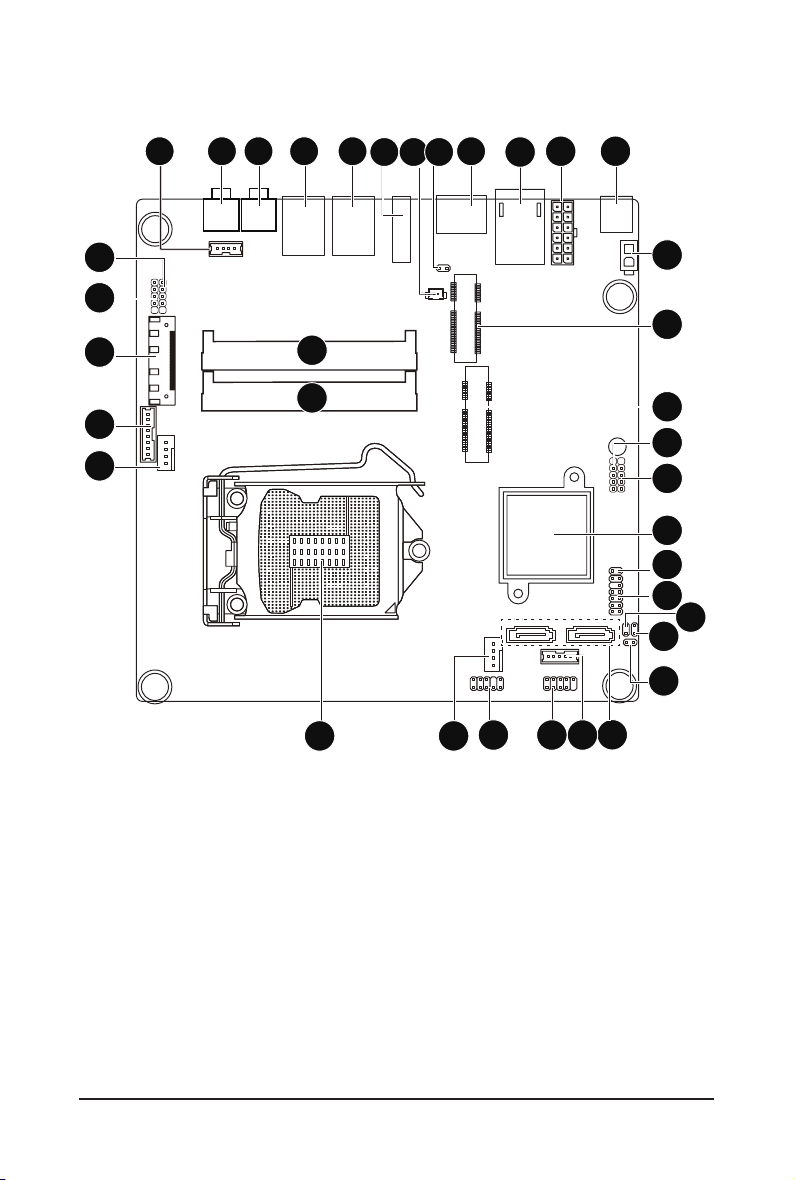
MSQ77DI Motherboard Layout
421 5
3
6
12
11
10
9
8
7
34
33
32
31
30
35
36
13
14
15
16
17
18
19
20
21
22
23
24
2829
252627
- 5 -

Item Code Description
1 SPEK Speaker cable connector
2 LINE_IN Audio Line In port
3 SPDIF Optical S/PDIF Out connector
4 R_USB2 USB 3.0 ports
5 R_USB1 USB 3.0 ports
6 HDMI1 HDMI port
7 BAT Battery cable connector
8 DP DisplayPort connector
9 CLR_CMOSHW Clear CMOS jumper
10 LAN RJ45 LAN port
11 PWRCON 12-pin power connector
12 DC_IN DC In power connector
13 AD_IN 2 pin power connector
14 MIN_PCIE1 Mini PCi Express connector
15 M_SATA MSATA connector
16 TP_USB Touch panel USB header
17 TV_USB TV tuner USB header
18 U52 Intel BD82Q77 Chipset
19 BL_SW Back Light switch
20 F_PANEL Front panel header
21 LAN LED LAN LED header
22 WF_LED Wireless LAN LED header
23 ME_LVDS_JP LVDS Enabled Jumper
24 SATA0/SATA1 SATA cable connectors
25 HDD_PWR Hard disk power connector
26 F_USB1 USB connector
27 F_AUDIO Audio cable connector
28 CPU_FAN CPU fan connector
29 CPU Intel LGA1155 socket
30 SYS_FAN System fan connector
31 FPD Flat Panel Display connector
32 LVDS LVDS connector
33 DMIC_CON Digital Mic connector
34 WEB_CON WEBCAM connector
35 SODIMMB1 DDR3 SO-DIMM slot (channel B-1 )
36 SODIMMA1 DDR3 SO-DIMM slot (channel A-1 )
- 6 -

Chapter 1 Hardware Installation
1-1 Installation Precautions
The motherboard contains numerous delicate electronic circuits and components which can
become damaged as a result of electrostatic discharge (ESD). Prior to installation, carefully read
the user's manual and follow these procedures:
• Prior to installation, do not remove or break motherboard S/N (Serial Number) sticker or
warranty sticker provided by your dealer. These stickers are required for warranty validation.
• Always remove the AC power by unplugging the power cord from the power outlet before
installing or removing the motherboard or other hardware components.
• When connecting hardware components to the internal connectors on the motherboard,
make sure they are connected tightly and securely.
• When handling the motherboard, avoid touching any metal leads or connectors.
• It is best to wear an electrostatic discharge (ESD) wrist strap when handling electronic com-
ponents such as a motherboard, CPU or memory. If you do not have an ESD wrist strap,
keep your hands dry and rst touch a metal object to eliminate static electricity.
• Prior to installing the motherboard, please have it on top of an antistatic pad or within an
electrostatic shielding container.
• Before unplugging the power supply cable from the motherboard, make sure the power sup-
ply has been turned off.
• Before turning on the power, make sure the power supply voltage has been set according to
the local voltage standard.
• Before using the product, please verify that all cables and power connectors of your hard-
ware components are connected.
• To prevent damage to the motherboard, do not allow screws to come in contact with the
motherboard circuit or its components.
• Make sure there are no leftover screws or metal components placed on the motherboard or
within the computer casing.
• Do not place the computer system on an uneven surface
• Do not place the computer system in a high-temperature environment.
• Turning on the computer power during the installation process can lead to damage to sys-
tem components as well as physical harm to the user.
• If you are uncertain about any installation steps or have a problem related to the use of the
product, please consult a certied computer technician.
.
- 7 - Hardware Installation
1-2 ProductSpecications
CPU Support for Intel® Core™ i7, Core™i5, Core™i3 processors/Intel® Pentium®
processors in the LGA1155 package
Support Up to 95W
L3 cache varies with CPU
Chipset Intel® BD82Q77 Platform Controller Hub
Memory 2 x 1.5V DDR3 SO-DIMM slot
Max. to 8GB (4GB x 2)
Dual channel architecture
Support for DDR3 1333/1600 MHz
Display 1 x HDMI 1.3 out
1 x LVDS slot
Audio Realtek ALC887 codec
High Denition Audio
2 Channel / SPDIF out
LAN 1 x Intel 82579LM supports 10/100/1000 Mbps
Supports AMT 8.0
Expansion Slots 1 x Mini PCI Express slot (Half size)
1 x Mini PCI Express slot (Full size/MSATA function/optional)
Onboard
Graphics
Storage Interface 2 x SATA 6Gb/s connectors
USB 4 x USB 3.0 ports (back panel)
Build in Intel® processor
5 x USB 2.0/1.1 headers (Card reader/Touch panel/webcam and other devices)
Internal
Connectors
Hardware Installation - 8 -
1 x 12-pin power connector
1 x 2-pin power connector
2 x SATA 6Gb/s connectors
1 x HDD power connector
1 x CPU fan header
1 x System fan header
1 x Front panel header
1 x Audio header
3 x USB 2.0 headers
1 x Speaker header
1 x LVDS connector
1 x FPD connector
1 x Web CAM header
1 x DMIC header
Back Panel
Connectors
1 x DC-IN
1 x RJ-45 port
1 x HDMI port
1 x DisplayPort connector
4 x USB 3.0 ports
1 x SPDIF Out port (Optical)
1 x Audio Line In
I/O Controller iTE IT8773 chip
Hardware
Monitor
CPU/System temperature detection
CPU fan speed detection
BIOS 1 x 64 Mbit ash
AMI BIOS
Form Factor Mini ITX Form Factor; 170cm x 170cm
* GIGA BYTE reserves the right to make any changes to the product specications and produc t-related infor mation
without prior notice.
- 9 - Hardware Installation
1-3 Installing the CPU and CPU Cooler
Read the following guidelines before you begin to install the CPU:
• Make sure that the motherboard supports the CPU.
(Go to GIGABYTE's website for the latest CPU support list.)
• Always turn off the computer and unplug the power cord from the power outlet before installing
the CPU to prevent hardware damage.
• Locate the pin one of the CPU. The CPU cannot be inserted if oriented incorrectly. (Or you may
locate the notches on both sides of the CPU and alignment keys on the CPU socket.)
• Apply an even and thin layer of thermal grease on the surface of the CPU.
• Do not turn on the computer if the CPU cooler is not installed, otherwise overheating and
damage of the CPU may occur.
• Set the CPU host frequency in accordance with the CPU specications. It is not recommended
that the system bus frequency be set beyond hardware specications since it does not meet the
standard requirements for the peripherals. If you wish to set the frequency beyond the standard
specifications, please do so according to your hardware specifications including the CPU,
graphics card, memory, hard drive, etc.
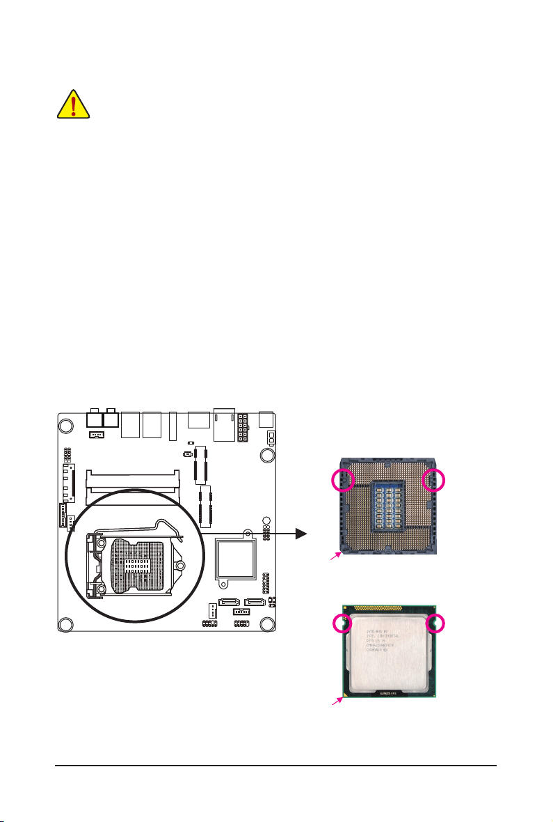
1-3-1 Installing the CPU
A. Locate the alignment keys on the motherboard CPU socket and the notches on the CPU.
LGA1155 CPU Socket
Alignment KeyAlignment Key
Pin One Corner of the CPU Socket
LGA1155 CPU
Notch
Triangle Pin One Marking on the CPU
Notch
- 10 - Hardware Installation
B. Follow the steps below to correctly install the CPU into the motherboard CPU socket.
Before installing the CPU, make sure to turn off the computer and unplug the power cord from
the power outlet power plug to prevent any damage to prevent damage to the CPU.
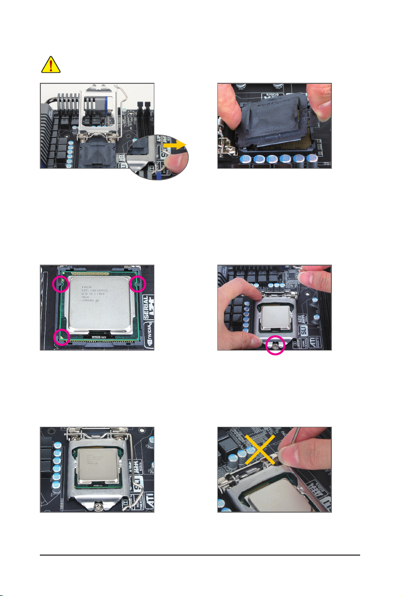
Step 1:
Gently press the CPU socket lever handle down
and away from the socket with your nger. Then
completely lift the CPU socket lever and the metal
load plate will be lifted as well.
Step 3:
Hold the CPU with your thumb and index ngers.
Align the CPU pin one marking (triangle) with the
pin one corner of the CPU socket (or you may
align the CPU notches with the socket alignment
keys) and gently insert the CPU into position.
Step 2:
Remove the CPU socket cover as shown. Hold
your index finger down on the rear grip of the
socket cover and use your thumb to lift up the
front edge (next to the "REMOVE" mark) and
then remove the cover. (DO NOT touch socket
contacts. To protect the CPU socket, always replace the protective socket cover when the CPU
is not installed.)
Step 4:
Once the CPU is properly inserted, use one
hand to hold the socket lever and use the other
to lightly replace the load plate. When replacing
the load plate, make sure the front end of the
load plate is under the shoulder screw.
Step 5:
Push the CPU socket lever back into its locked
position.
Hardware Installation - 11 -
NOTE:
Hold the CPU socket lever by the handle, not the
lever base portion.
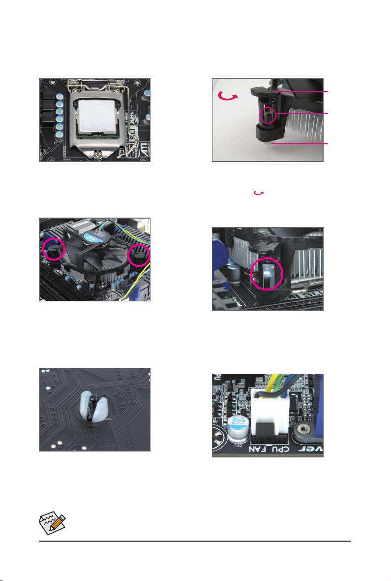
1-3-2 Installing the CPU Cooler
Follow the steps below to correctly install the CPU cooler on the motherboard. (The following procedure uses
Intel® boxed cooler as the example cooler.)
Male Push
Pin
Direction of the
Arrow Sign on
the Male Push
Pin
The Top
of Female
Push Pin
Female
Push Pin
Step 1:
Apply an even and thin layer of thermal paste on
the surface of the installed CPU.
Step 3:
Place the cooler atop the CPU, aligning the four
push pins through the pin holes on the motherboard. Push down on the push pins diagonally.
Step 2:
Before installing the cooler, note the direction of
the arrow sign on the male push pin. (Turning
the push pin along the direction of the arrow is
for removing the cooler, and the opposite
direction is for installing it..)
Step 4:
You should hear a "click" when pushing down
each push pin. Check that the Male and Female
push pins are joined closely. (Refer to your CPU
cooler installation manual for instructions on
installing the cooler.)
Step 5:
After the installation, check the back of the moth-
erboard. If the push pin is inserted as the picture
above shows, the installation is complete.
Step 6:
Finally, attach the power connector of the CPU
cooler to the CPU fan header (CPU_FAN) on the
motherboard.
Use extreme care when removing the CPU cooler because the thermal grease/tape between the
CPU cooler and CPU may adhere to the CPU. Inadequately removing the CPU cooler may damage
the CPU.
- 12 - Hardware Installation
1-4 Installing the Memory
Read the following guidelines before you begin to install the memory:
• Make sure that the motherboard supports the memory. It is recommended that memory of the
same capacity, brand, speed, and chips be used.
• Always turn off the computer and unplug the power cord from the power outlet before installing
the memory to prevent hardware damage.
• Memory modules have a foolproof design. A memory module can be installed in only one
direction. If you are unable to insert the memory, switch the direction.
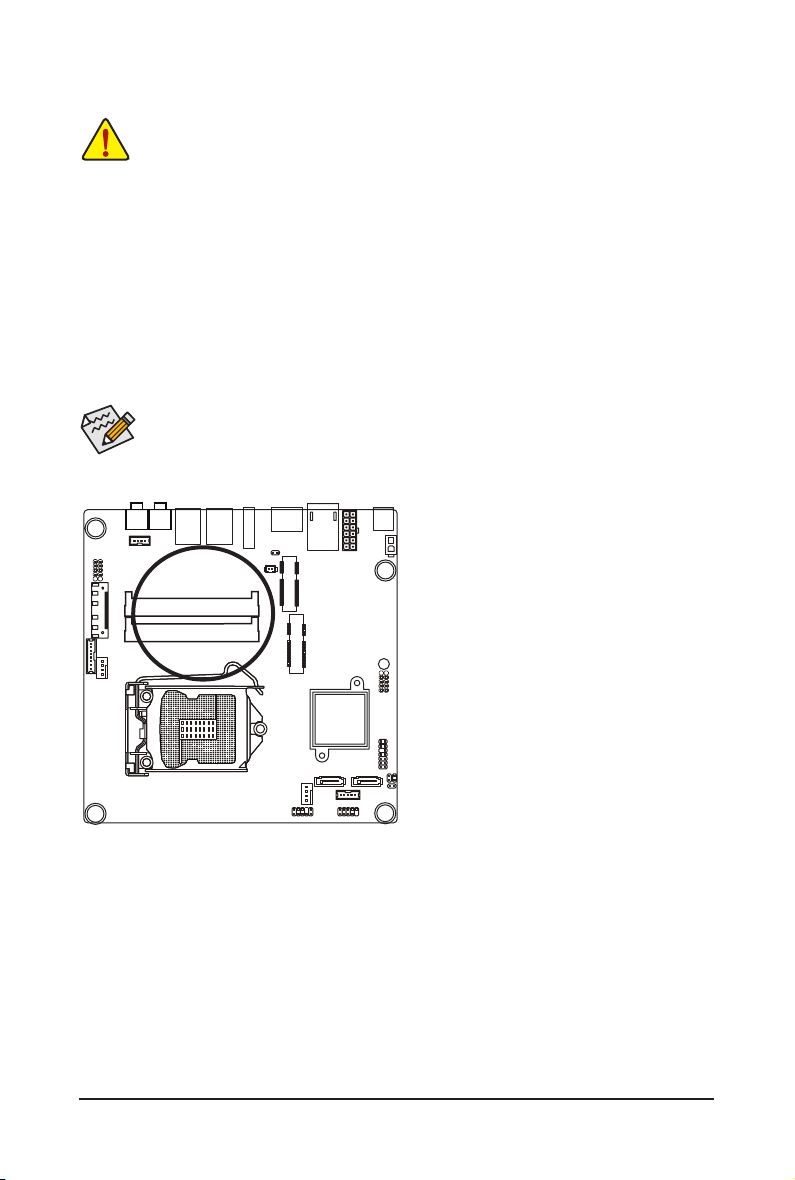
1-4-1 DualChannelMemoryConguration
This motherboard provides two DDR3 memory sockets and supports Dual Channel Technology. After the
memory is installed, the BIOS will automatically detect the specications and capacity of the memory. Enabling Dual Channel memory mode will double the original memory bandwidth.
NOTE!
• DIMM must be populated in order starting from SODIMMB1 socket. For Dual-channel operation,
DIMMs must be installed in matched pairs.
SODIMMB1
SODIMMA1
Due to CPU limitations, read the following guidelines before installing the memory in Dual Channel mode.
1. Dual Channel mode cannot be enabled if only one DDR3 memory module is installed.
2. When enabling Dual Channel mode with two memory modules, it is recommended that memory of
the same capacity, brand, speed, and chips be used for optimum performance.
Hardware Installation - 13 -
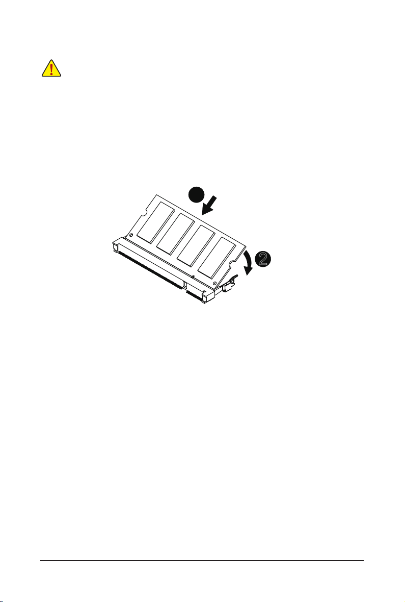
1-4-2 Installing a Memory
Before installing a memory module, make sure to turn off the computer and unplug the power
cord from the power outlet to prevent damage to the memory module.
Be sure to install DDR3 DIMMs on this motherboard.
Installation Step:
Step 1. Align the memory with the DIMM module and insert the DIMM memory module into the DIM slot.
Please note that memory module has a foolproof insertion design. A memory module can be
installed In only one direction.
Step 2. Push down the memory and seat it rmly.
Step 3. Reverse the installation steps when you wish to remove the DIMM module.
1
2
- 14 - Hardware Installation
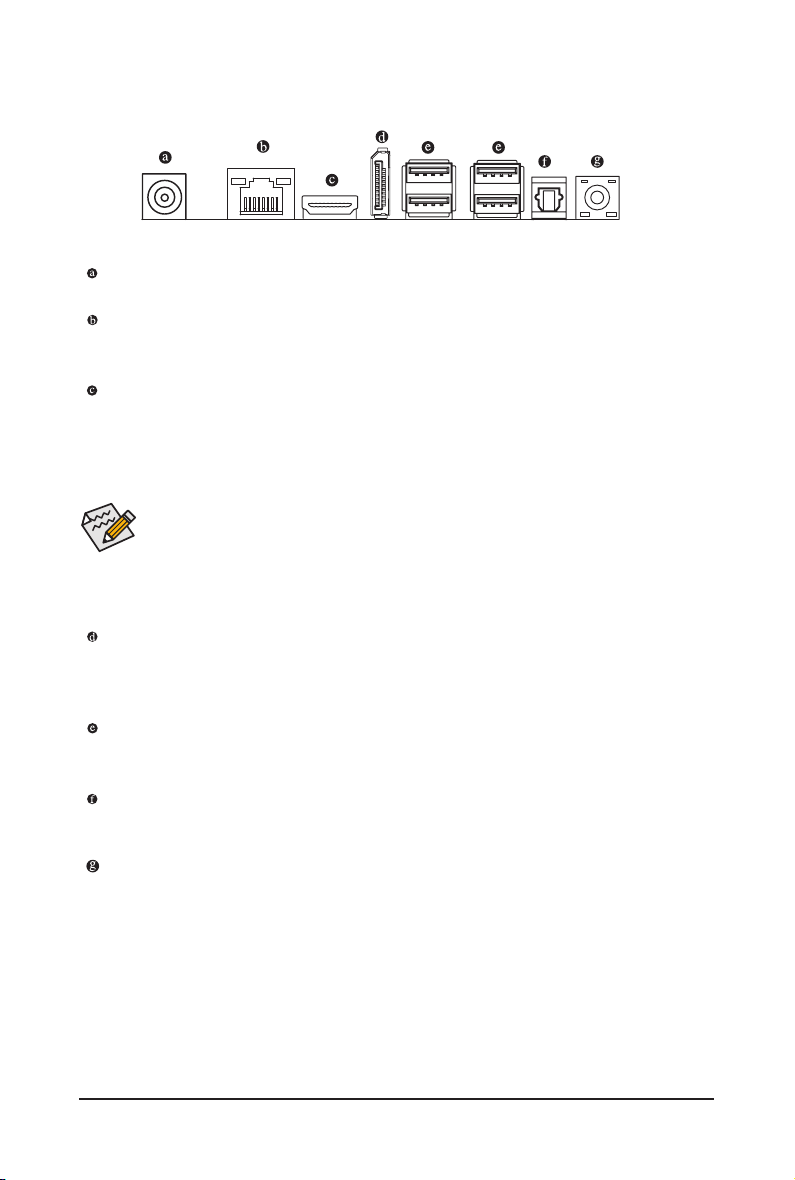
1-5 Back Panel Connectors
DC Power Jack
Connect the DC power to this port.
RJ-45 LAN Port
The Gigabit Ethernet LAN port provides Internet connection at up to 1 Gbps data rate. The following
describes the states of the LAN port LEDs.
HDMI Port
The HDMI (High-Denition Multimedia Interface) provides an all-digital audio/video interface to
transmit the uncompressed audio/video signals and is HDCP compliant. Connect the HDMI
audio/video device to this port. The HDMI Technology can support a maximum resolution of
1920x1080p but the actual resolutions supported depend on the monitor being used.
• When After installing the HDMI device, make sure the default device for sound playback is the
HDMI device. (The item name may differ by operating system. Refer the gures below
for details.), and enter BIOS Setup, then set Onboard VGA output connect to D-SUB/
HDMI under Advanced BIOS Features..
• Please note the HDMI audio output only supports AC3, DTS and 2-channel-LPCM
formats. (AC3 and DTS require the use of an external decoder for decoding.)
DP (DisplayPort) Connector
DisplayPort is a digital display interface which is primarily used to connect a video source to a display
device such as a computer monitor, though it can also be used to transmit audio, USB, and other forms
of data.
USB 3.0 Ports
The USB port supports the USB 3.0 specication. Use this port for USB devices such as a USB keyboard/mouse, USB printer, USB ash drive and etc.
Optical S/PDIF Out Connector
This connector provides digital audio out to an external audio system that supports digital optical audio.
Before using this feature, ensure that your audio system provides an optical digital audio in connector.
Line In Jack (Blue)
The default line in jack. Use this audio jack for line in devices such as an optical drive, walkman, etc.
- 15 - Hardware Installation
 Loading...