

Page 1

MNIC8PI/MNIC8QI
Intel® N455/D525 Processor Motherboards
User's Manual
Rev. 1001
Page 2

Copyright
© 2010 GIGA-BYTE TECHNOLOGY CO., LTD. All rights reserved.
The trademarks mentioned in this manual are legally registered to their respective owners.
Disclaimer
Information in this manual is protected by copyright laws and is the property of GIGABYTE.
Changes to the specifications and features in this manual may be made by GIGABYTE
without prior notice. No part of this manual may be reproduced, copied, translated, transmitted,
or published in any form or by any means without GIGABYTE's prior written permission.
Documentation Classications
In order to assist in the use of this product, GIGABYTE provides the following types of documentations:
For quick set-up of the product, read the Quick Installation Guide included with the product.
For detailed product information, carefully read the User's Manual.
For product-related information, check on our website at:
http://www.gigabyte.com
Page 3

- 3 -
Table of Contents
MNIC8PI/MNIC8QI Motherboard Layout ......................................................................... 4
Chapter 1 Hardware Installation .....................................................................................6
1-1 Installation Precautions .................................................................................... 6
1-2 ProductSpecications ...................................................................................... 7
1-3 Installing the Memory ....................................................................................... 9
1-3-1 Installing a Memory .................................................................................................9
1-4 Back Panel Connectors .................................................................................. 10
1-5 Internal Connectors ........................................................................................ 12
Chapter 2 BIOS Setup ..................................................................................................27
2-1 The Main Menu .............................................................................................. 29
2-2 Advanced Menu ............................................................................................. 31
2-2-1 CPUConguration ..................................................................................................32
2-2-2 IDEConguration ...................................................................................................33
2-2-3 SerialandParallelPortConguration ....................................................................35
2-2-4 HardwareHealthConguration ..............................................................................36
2-2-5 ACPIConguration .................................................................................................38
2-2-6 USBConguration ..................................................................................................39
2-3 Boot Menu ...................................................................................................... 40
2-4 Security Menu ................................................................................................ 43
2-5 Chipset Menu ................................................................................................. 44
2-5-1 NorthBridgeConguration .....................................................................................45
2-5-2 SouthBridgeConguration ....................................................................................46
2-5-3 OnboardPeripherialsConguration .......................................................................47
2-6 Exit Menu ....................................................................................................... 49
Page 4
- 4 -
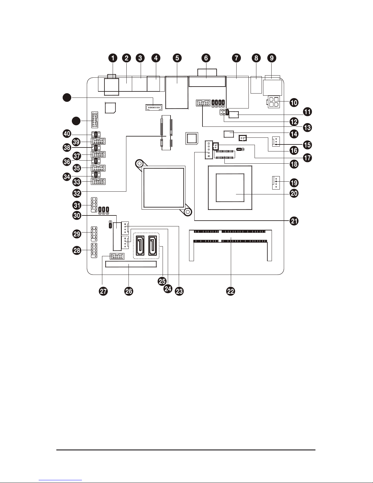
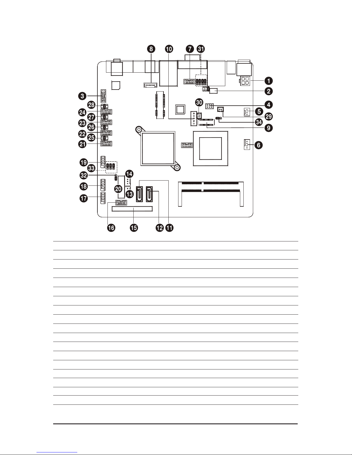
MNIC8PI/MNIC8QI Motherboard Layout
41
42
Page 5

- 5 -
Item Code Description
1 AUDIO_JACK Audio jack
2 LPT Parallel port
3 RJ11 Cash drawer port
4 KB_MS1 PS/2 connector
5 USB_LAN1 USB ports and LAN port
6 VGA1/COM2 VGA port and Serial port
7 COM4_USB1 Serial and USB Port
8 +12V_OUT DC jack
9 DC_IN DC jack
10 DC_OUT 4 pin power connector
11 VFD_JR1 VFD & RS232 Mode select jumper
12 JCOM4 Serail port 5V,12V, RI select jumper
13 VGA2 VGA cable connector
14 JRS1 RS232,RS422,RS485 Select
connector
15 SYS_FAN System fan cable connector
16 LCDPWR_CON LCD power connector
17 BKLTEN_CON Back light inverter jumper
18 LVDS LVDS connectors
19 CPU_FAN CPU fan cable connector
20 CPU Processor
21 INV_BRIG1 Inverter with box header
22 SO-DIMM DDR3 SO-DIMM slot
23 SATAPW2 SATA power connector
24 SATAPW1 SATA power connector
25 SATA1/2 SATA cable connectors
26 SATA 3 SATA 7+15 pins cable connector
27 JFRONT Front panel connecotor
28 F_USB3 Front USB cable connector
29 F_USB2 Front USB cable connector
30 BAT1 Battery socket
31 F_USB1 Front USB cable connector
32 MINI_CARD Mini PCI Express slot
33 COM6 Serial cable connector
34 JCOM6 Power COM select jumper
35 COM3 Serial cable connector
36 JCOM3 Power COM select jumper
37 COM5 Serial cable connector
38 JCOM5 Power COM select jumper
39 COM1 Serial cable connector
40 JCOM1 Power COM select jumper
41 F_AUDIO Front audio cable connector
42 KB_MS2 PS/2 cable connector
Page 6

- 6 - Hardware Installation
1-1 Installation Precautions
The motherboard contains numerous delicate electronic circuits and components which can
become damaged as a result of electrostatic discharge (ESD). Prior to installation, carefully read
the user's manual and follow these procedures:
• Prior to installation, do not remove or break motherboard S/N (Serial Number) sticker or
warranty sticker provided by your dealer. These stickers are required for warranty validation.
• Always remove the AC power by unplugging the power cord from the power outlet before
installing or removing the motherboard or other hardware components.
• When connecting hardware components to the internal connectors on the motherboard,
make sure they are connected tightly and securely.
• When handling the motherboard, avoid touching any metal leads or connectors.
• It is best to wear an electrostatic discharge (ESD) wrist strap when handling electronic com-
ponents such as a motherboard, CPU or memory. If you do not have an ESD wrist strap,
keep your hands dry and rst touch a metal object to eliminate static electricity.
• Prior to installing the motherboard, please have it on top of an antistatic pad or within an
electrostatic shielding container.
• Before unplugging the power supply cable from the motherboard, make sure the power sup-
ply has been turned off.
• Before turning on the power, make sure the power supply voltage has been set according to
the local voltage standard.
• Before using the product, please verify that all cables and power connectors of your hard-
ware components are connected.
• To prevent damage to the motherboard, do not allow screws to come in contact with the
motherboard circuit or its components.
• Make sure there are no leftover screws or metal components placed on the motherboard or
within the computer casing.
• Do not place the computer system on an uneven surface
.
• Do not place the computer system in a high-temperature environment.
• Turning on the computer power during the installation process can lead to damage to sys-
tem components as well as physical harm to the user.
• If you are uncertain about any installation steps or have a problem related to the use of the
product, please consult a certied computer technician.
Chapter 1 Hardware Installation
Page 7
Hardware Installation - 7 -
1-2 ProductSpecications
CPU Supports single Intel® N455 processor (MNIC8PI)
Supports single Intel® D525 processor (MNIC8QI)
Supports 1.66GHz (MNIC8PI)
Supports 1.8GHz (MNIC8QI)
Chipset Intel® ICH8M
Memory 1 x SO-DIMM slot support DDR3 800/1066
Support up 2GB (MNIC8PI)
Support up 4GB (MNIC8QI)
Audio Realtek® ALC269 codec
High Denition Audio
2 channel
LAN 1 x Realtek® RTL 8111E supports 10/100/1000 Mbps
Expansion Slots 1 x mini PCI Express x1 slot
Onboard
Graphics
Build in Intel® ICH8M chipset
Storage Interface 2 x SATA 3Gb/s connectors
1 x 7 pin & 15 pin SATA connector
USB Up to 10 USB 2.0/1.1 ports (4 on the back panel, 6 via the USB brackets
connected to the internal USB headers)
Internal
Connectors
1 x 4 pin ATX 12V power connector
2 x SATA 3Gb/s connectors
2 x SATA power connectors
1 x 7 pin & 15 pin SATA connector
1 x CPU fan header
1 x System fan header
4 x COM power select connector
1 x front panel header
1 x audio header*
3 x USB 2.0 headers
1 x VGA header
1 x LVDS connector
Back Panel
Connectors
1 x DC-in (12V) connector
1 x DC-out (12V) connector
4 x USB 2.0 ports
1 x RJ-45 port
1 x VGA port
2 x COM ports
1 x Parallel port
1 x RJ-11 port
1 x Audio jack
1 x PS/2 connector
Page 8

- 8 - Hardware Installation
Form Factor Mini ITX Form Factor; 6.75 inch x 6.75 inch
* GIGABYTE reserves the right to make any changes to the product specications and product-related information
without prior notice.
Page 9
Hardware Installation - 9 -
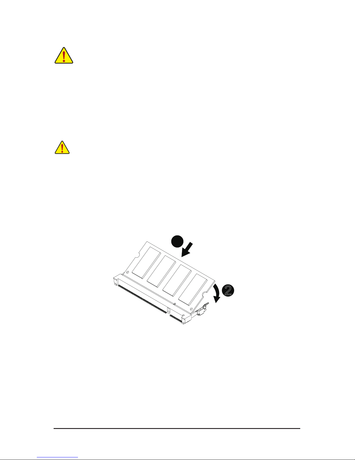
1-3 Installing the Memory
Read the following guidelines before you begin to install the memory:
• Make sure that the motherboard supports the memory. It is recommended that memory of the
same capacity, brand, speed, and chips be used.
• Always turn off the computer and unplug the power cord from the power outlet before installing
the memory to prevent hardware damage.
• Memory modules have a foolproof design. A memory module can be installed in only one direction. If you are unable to insert the memory, switch the direction.
1-3-1 Installing a Memory
Before installing a memory module, make sure to turn off the computer and unplug the power
cord from the power outlet to prevent damage to the memory module.
Be sure to install DDR3 DIMMs on this motherboard.
Installation Step:
Step 1. Align the memory with the DIMM module and insert the DIMM memory module into the DIMM slot.
Please note that memory module has a foolproof insertion design. A memory module can be
installed In only one direction.
Step 2. Push down the memory and seat it rmly.
Step 3. Reverse the installation steps when you wish to remove the DIMM module.
2
1
Page 10
- 10 - Hardware Installation
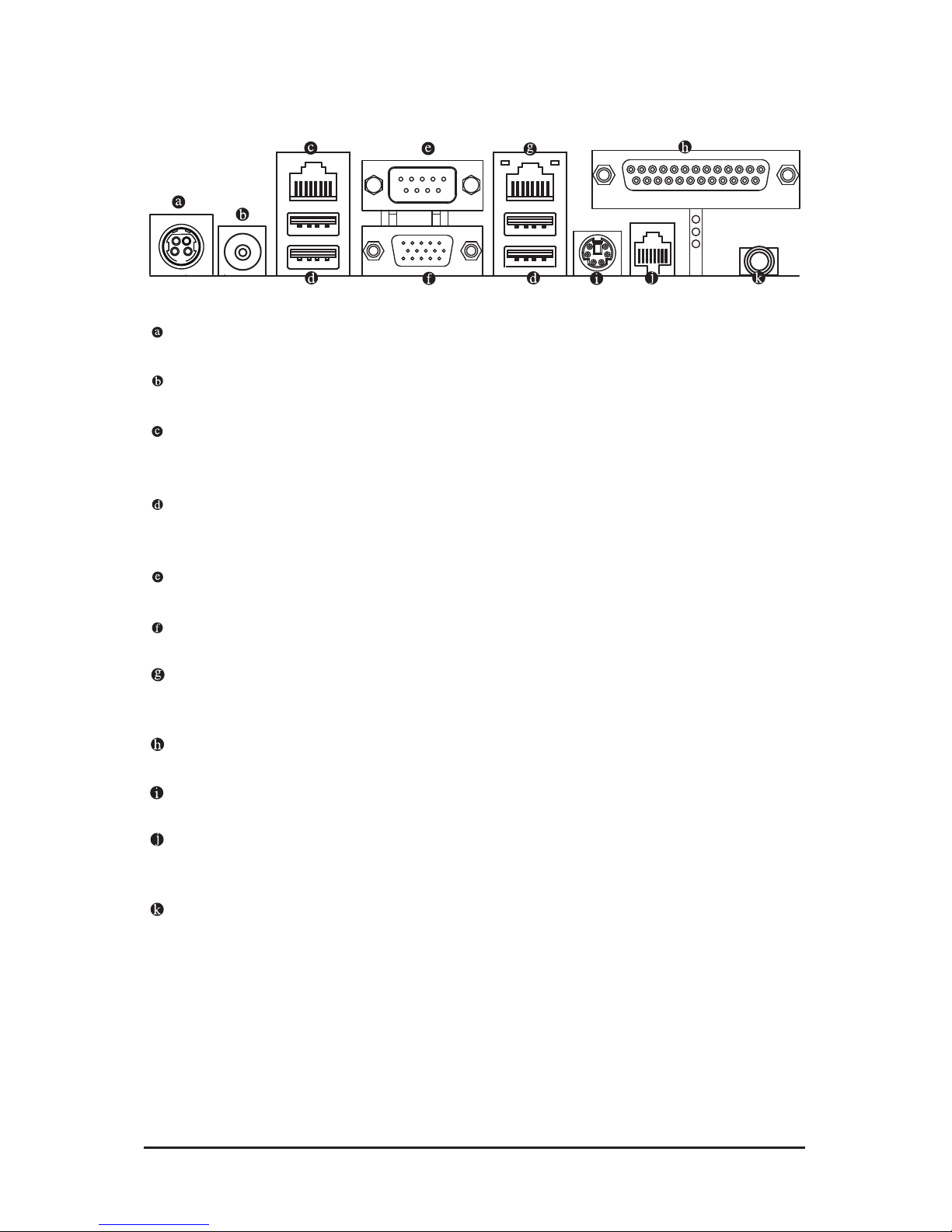
1-4 Back Panel Connectors
DC In Port
Connect the DC power to this port.
12V DC Out Port
Connect the 12V DC power to this port.
RS-232 Port
Connects this port to the serial-based modems, printers, mice, data storage, un-interruptible power supplies, and other peripheral devices
USB 2.0/1.1 Port
The USB port supports the USB 2.0/1.1 specication. Use this port for USB devices such as a USB keyboard/mouse, USB printer, USB ash drive and etc.
Serial Port
Connects to serial-based mouse or data processing devices.
Video Port
The video in port allows connect to video in, which can also apply to video loop thru function.
RJ-45 LAN Port
The Gigabit Ethernet LAN port provides Internet connection at up to 1 Gbps data rate. The following
describes the states of the LAN port LEDs.
Parallel Port
The parallel port allows connection of a printer, scanner and other peripheral devices.
PS/2 Port
Use this port to connect a PS/2 mouse or a PS/2 keyboard.
RJ-11 Port
The RJ-11 (Cash Drawer) port is a physical connector interface most often used for telephone wire terminals.
Line Out Jack ((Front Speaker Out/Blue)
The default Line Out (Front Speaker Out) jack. Stereo speakers, earphone or front surroundspeakers
can be connected to Line Out (Front Speaker Out) jack.
Page 11

- 11 - Hardware Installation
• When removing the cable connected to a back panel connector, rst remove the cable from your
device and then remove it from the motherboard.
• When removing the cable, pull it straight out from the connector. Do not rock it side to side to
prevent an electrical short inside the cable connector.
Activity LED
Connection/
Speed LED
LAN Port
Activity LED:Connection/Speed LED:
State Description
Orange 1 Gbps data rate
Green 100 Mbps data rate
Off 10 Mbps data rate
State Description
Blinking Data transmission or receiving is occurring
Off No data transmission or receiving is occurring
Page 12
Hardware Installation - 12 -
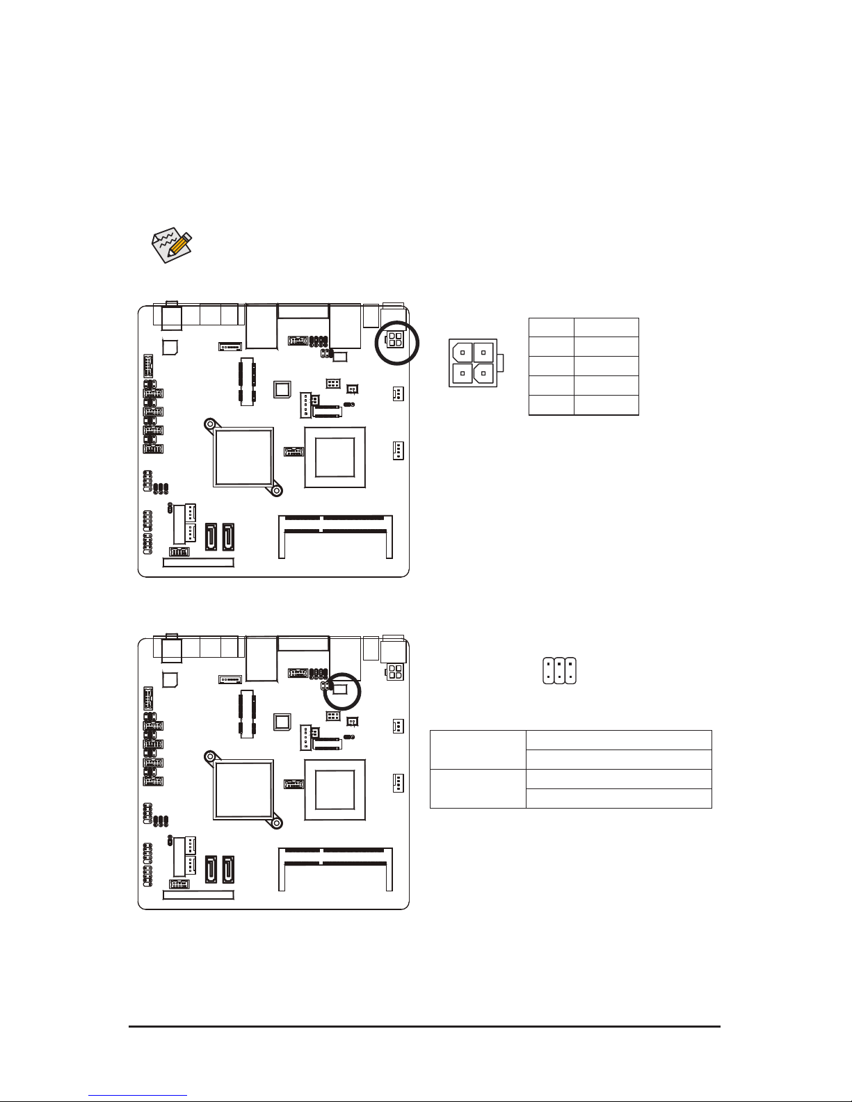
1-5 Internal Connectors
1) DC_OUT 19) F_US B1
2) VFD_JR1 20) BAT1
3) F_ AUDI O 21) COM6
4) JRS1 22) COM3
5) SYS_FAN 23) COM5
6) CPU_FAN 24) COM1
7) VGA2 25) JCOM6
8) KB_MS2 26) JCOM3
9) LVDS 27) JCOM5
10) INV_BRIG1 28) JCOM1
11) SATA2 29) LCDPWR_CON
12) SATA1 30) BKLTEN_CON
13) SATAPW_1 31) JRS2/JRS3/JRS4/JRS5
14) SATAPW_2 32) CLR_CMOS1
15) S ATA3 33) USB_PWR1/USB_PWR2/USB_PWR3
16) JFRONT 34) LVDS_PWR1
17) F_USB3
18) F_U S B2
Page 13

- 13 - Hardware Installation
Read the following guidelines before connecting external devices:
• First make sure your devices are compliant with the connectors you wish to connect.
• Before installing the devices, be sure to turn off the devices and your computer. Unplug the
power cord from the power outlet to prevent damage to the devices.
• After installing the device and before turning on the computer, make sure the device cable has
been securely attached to the connector on the motherboard.
Page 14
Hardware Installation - 14 -
2
1
4
3
1) DC_OUT (2x2 12V Power Connector)
With the use of the power connector, the power supply can supply enough stable power to all the com-
ponents on the motherboard. Before connecting the power connector, rst make sure the power supply
is turned off and all devices are properly installed. The power connector possesses a foolproof design.
Connect the power supply cable to the power connector in the correct orientation. The 12V power connector mainly supplies power to the CPU. If the 12V power connector is not connected, the computer will
not start.
To meet expansion requirements, it is recommended that a power supply that can withstand high
power consumption be used (500W or greater). If a power supply is used that does not provide
the required power, the result can lead to an unstable or unbootable system.
Pin No. Denition
1 GND
2 GND
3 +12V
4 +12V
2) VFD_JR1 (VFD & RS232 Mode Select Jumper)
1 5
62
VFD Mode VFD_JR1: 1-2, 3-5, 4-6 Close
JCOM4: 5-6 Close
RS232 Mode VFD_JR1: 1-3, 2-4 Close
JCOM4: 1-2 or 3-4 Close
Page 15
- 15 - Hardware Installation
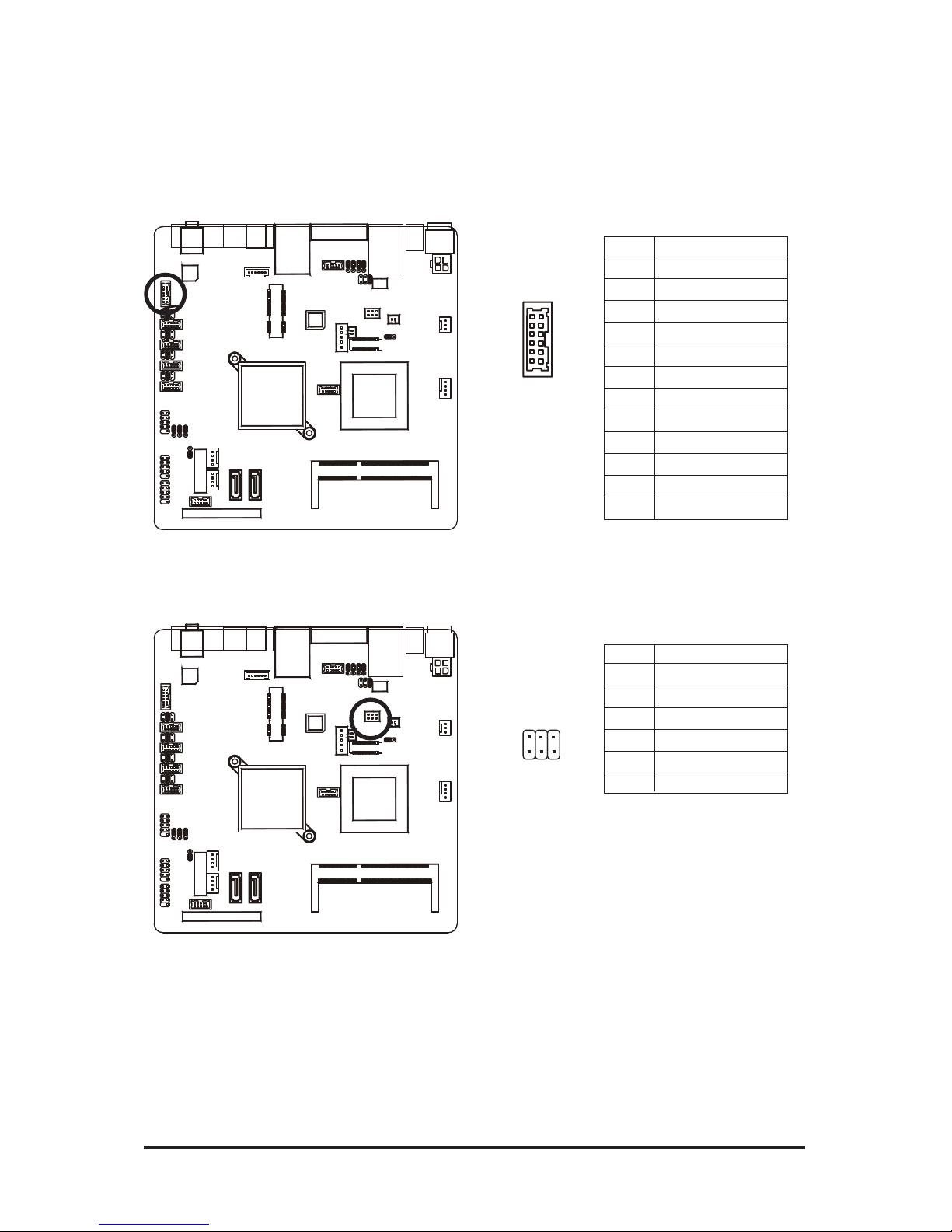
3) F_AUDIO (Front Panel Audio Header)
The front panel audio header supports Intel High Denition audio (HD) and AC'97 audio. You may connect
your chassis front panel audio module to this header. Make sure the wire assignments of the module connector match the pin assignments of the motherboard header. Incorrect connection between the module
connector and the motherboard header will make the device unable to work or even damage it.
4) JRS1 (RS232/RS422/RS485 Select Header)
Pin No. Denition
1 Amplier Out_R+
2 MIC_L
3 Amplier Out_R-
4 MIC_R
5 GND
6 Line In_R
7 Amplier Out_L+
8 Line In_L
9 Amplier Out_L-
10 Line In_JD
11 GND
12 External MIC JD
Pin No. Denition
1 RS232
2 UART RXD Signal
3 RS422
4 UART RXD Signal
5 RS485
6 UART RXD Signal
2 1
12
11
1 5
62
Page 16

- 16 - Hardware Installation
5/6) SYS_FAN/CPU_FAN (System Fan/CPU Fan Headers)
The motherboard has a 4-pin CPU fan header (CPU_FAN), a 3-pin (SYS_FAN) system fan headers.
Most fan headers possess a foolproof insertion design. When connecting a fan cable, be sure to connect
it in the correct orientation (the black connector wire is the ground wire). The motherboard supports CPU
fan speed control, which requires the use of a CPU fan with fan speed control design. For optimum heat
dissipation, it is recommended that a system fan be installed inside the chassis.
• Be sure to connect fan cables to the fan headers to prevent your CPU and system from overheating. Overheating may result in damage to the CPU or the system may hang.
• These fan headers are not conguration jumper blocks. Do not place a jumper cap on the
headers.
SYS_FAN (System Fan):
Pin No. Denition
1 GND
2 +12V / Speed Control
3 Sense
CPU_FAN (CPU Fan):
Pin No. Denition
1 GND
2 +12V / Speed Control
3 Sense
4 Speed Control
CPU_FAN
1
DEBUG
PORT
CPU_FAN
1
FDD
ATX
ATX_12V
SYS_FAN1
SYS_FAN
7) VGA2 (VGA Cable Header)
Pin No. Denition
1 V-SYNC
2 H-SYNC
3 GND
4 GND
5 RED
6 GND
7 GREEN
8 DDC Clock
9 BLUE
10 DDC Data
1 9
102
Page 17

- 17 - Hardware Installation
8) KB_MS2 (PS/2 Cable Header)
1 6
Pin No. Denition
1 GND
2 KDAT
3 F_KDAT
4 KCLK
5 F_KCLK
6 5V
9) LVDS (LVDS Headers)
LVDS stands for Low-voltage differential signaling, which uses high-speed analog circuit
techniques to provide multigigabit data transfers on copper interconnects and is a generic interface
standard for high-speed data transmission.
1 GND 16 GND
2 NC 17 Data1-
3 EDID Data 18 GND
4 GND 19 GND
5 EDID Clock 20 Backlight 5V
6 NC 21 LVDS Clock-
7 GND 22 Backlight 5V
8 NC 23 LVDS Clock+
9 Data0+ 24 Backlight 5V
10 NC 25 GND
11 Data0- 26 GND
12 Backlight Enable 27 Data2-
13 GND 28 LVDS Power 3.3V
14 Backlight Controller 29 Data2+
15 Data1+ 30 LVDS Power 3.3V
1 29
302
Page 18

Hardware Installation - 18 -
10) INV_BRIG1 (Inverter With Box Header)
1
5
Pin No. Denition
1 12V Power
2 12V Power
3 GND
4 Backlight Controller
5 Backlight Enable
11/12) SATA1/2 (SATA 3Gb/s Connectors)
The SATA connectors conform to SATA 3Gb/s standard and are compatible with SATA 1.5Gb/s standard.
Each SATA connector supports a single SATA device.
Pin No. Denition
1 GND
2 TXP
3 TXN
4 GND
5 RXN
6 RXP
7 GND
• A RAID 0 or RAID 1 conguration requires at least two hard drives. If more than two hard
drives are congured, the total number of hard drives must be an even number.
• A RAID 5 conguration requires at least three hard drives. (The total number of hard drives
does not have to be an even number.)
• A RAID 10 conguration requires four hard drives.
1 1
SATA 1SATA 2
7 7
DEBUG
PORT
G.QBOFM
DEBUG
PORT
G.QBOFM
(Note) When a RAID conguration is built across the SATA 3Gb/s channels, the system performance of
the RAID conguration may vary depends on the devices are connected.
SATA 1
SATA 2
Page 19

- 19 - Hardware Installation
15) SATA3 (SATA 7+15 Pins Header)
13/14) SATAPW_1/SATAPW_2 (SATA HDD Power Headers)
1
4
Pin No. Denition
1 +12V
2 GND
3 GND
4 5V
SATAPW2SATAPW1
Page 20

Hardware Installation - 20 -
16) JFRONT (Front Panel Header)
Connect the power switch, reset switch, speaker, chassis intrusion switch/sensor and system status
indicator on the chassis to this header according to the pin assignments below. Note the positive and
negative pins before connecting the cables.
9
102
1
The front panel design may differ by chassis. A front panel module mainly consists of power
switch, reset switch, power LED, hard drive activity LED, speaker and etc. When connecting your
chassis front panel module to this header, make sure the wire assignments and the pin assignments are matched correctly.
Pin No. Pin Denition
1 Stand-by LED Signal
2 Power LED Signal
3 Power Switch
4 Ground
5 LAN Act LED Signal
6 LAN Act LED 5V
7 HDD LED
8 VCC 5V
9 Reset Button
10 Ground
Page 21

Hardware Installation - 21 -
17/18/19) F_USB3/F_USB2/F_USB1 (USB Headers)
The headers conform to USB 2.0/1.1 specication. Each USB header can provide two USB ports via an
optional USB bracket. For purchasing the optional USB bracket, please contact the local dealer.
COMB
Smart Card Reader
SPDIF
AUX_IN
CD_IN
Secure Gigital /
Memory Stick
Serial ATA
F_USB
F_1394
CPU_FAN
SYS_FAN
PWR_FAN
COMB
192
10
F_USB2
F_USB3
F_USB3F_USB1/F_USB2
F_USB1
Pin No. Denition
1 Power (5V)
2 Power (5V)
3 USB DX-
4 USB DY-
5 USB DX+
6 USB DY+
7 GND
8 GND
9 No Pin
10 NC
Pin No. Denition
1 Power (5V)
2 Power (5V)
3 USB DX-
4 NC
5 USB DX+
6 NC
7 GND
8 GND
9 No Pin
10 NC
When the system is in S4/S5 mode, only the USB ports routed to the F_USB1 header can
support the ON/OFF Charge function.
Page 22

- 22 - Hardware Installation
20) BAT1 (Battery)
The battery provides power to keep the values (such as BIOS congurations, date, and time information)
in the CMOS when the computer is turned off. Replace the battery when the battery voltage drops to a
low level, or the CMOS values may not be accurate or may be lost.
You may clear the CMOS values by removing the battery:
1. Turn off your computer and unplug the power cord.
2. Gently remove the battery from the battery holder and wait for
one minute. (Or use a metal object like a screwdriver to touch
the positive and negative terminals of the battery holder, making them short for 5 seconds.)
3. Replace the battery.
4. Plug in the power cord and restart your computer.
• Always turn off your computer and unplug the power cord before replacing the battery.
• Replace the battery with an equivalent one. Danger of explosion if the battery is replaced with an incorrect model.
• Contact the place of purchase or local dealer if you are not able to replace the battery by yourself or uncertain about the bat-
tery model.
• When installing the battery, note the orientation of the positive side (+) and the negative side (-) of the battery (the positive
side should face up).
• Used batteries must be handled in accordance with local environmental regulations.
21/22/23/24) COM6/COM3/COM5/COM1 (Serial Port Header)
The COM header can provide one serial port via an optional COM port cable. For purchasing the op-
tional COM port cable, please contact the local dealer.
COM6
COM5
COM1
COM3
Pin No. Denition
1 DCD
2 DSR
3 RXD
4 RTS
5 TXD
6 CTS
7 DTR
8 RI/+5V/+12V
9 GND
10 RI/+5V/+12V
129
10
Page 23

- 23 - Hardware Installation
25/26/27/28) JCOM6/JCOM3/JCOM5/JCOM1 (5V/12V/RI for Serial Port Option Header)
29) LCDPWR_CON (LCD Power ON/OFF Jumper)
JCOMS6
JCOMS3
JCOMS5
JCOMS1
6512
6512
6512
1-2 Close: 5V (Power COM)
3-4 Close: RI (STAND COM)
5-6 Close: 12V (Power COM)
Open: Power off.
Short: Power On.
Page 24

Hardware Installation - 24 -
30) BKLTEN_CON (Back light Inverter Enable/Disable Jumper)
31) JRS2/JRS3/JRS4/JRS5 (RS232/RS422/RS485 Mode Select Jumper)
Open: Disable Back light Inverter.
Short: Enable Back light Inverter.
JRS2 JRS3 JRS4 JRS5
1
Pin No. Denition
1 RS485 D- Signal
2 COM2 Pin 1
3 RS232 DCD Signal
JRS2
Pin No. Denition
1 RS485 D+ Signal
2 COM2 Pin 2
3 RS232 RXD Signal
JRS3
Pin No. Denition
1 RS422 D- Signal
2 COM2 Pin 4
3 RS232 DTR Signal
JRS4
Pin No. Denition
1 RS422 D- Signal
2 COM2 Pin 3
3 RS232 TXD Signal
JRS5
Page 25

Hardware Installation - 25 -
32) CLR_CMOS1 (Clearing CMOS Jumper)
Use this jumper to clear the CMOS values (e.g. date information and BIOS congurations) and reset
the CMOS values to factory defaults. To clear the CMOS values, place a jumper cap on the two pins to
temporarily short the two pins or use a metal object like a screwdriver to touch the two pins for a few
seconds.
1-2 Close: Clear CMOS data)
1-2 Close: VCC 5V. (Default setting)
2-3 Close: Normal operation (Default setting)
2-3 Close: Stand-by 5V.
• Always turn off your computer and unplug the power cord from the power outlet before clearing the CMOS
values.
• After clearing the CMOS values and before turning on your computer, be sure to remove the jumper cap from
the jumper. Failure to do so may cause damage to the motherboard.
• After system restart, go to BIOS Setup to load factory defaults (select Load Optimized Defaults) or manually
congure the BIOS settings (refer to Chapter 2, "BIOS Setup," for BIOS congurations).
1
1
1
1
33)
USB_PWR1/USB_PWR2/USB_PWR3 (USB Stand-by 5V/VCC 5V Select Jumper
)
USB_PWR1
USB_PWR2
USB_PWR3
Pin No. Denition
1 VCC 5V
2 USB Power input
3 Stand-by 5V
Page 26

- 26 - Hardware Installation
1-2 Close: 3.3V. (Default setting)
2-3 Close: 5V.
1
1
34)
LVDS _ PWR1 (LVDS 3V/5V Select Jumper
)
Pin No. Denition
1 3.3V
2 Power input
3 5V
Page 27

- 27 - BIOS Setup
BIOS (Basic Input and Output System) records hardware parameters of the system in the CMOS on the
motherboard. Its major functions include conducting the Power-On Self-Test (POST) during system startup,
saving system parameters and loading operating system, etc. BIOS includes a BIOS Setup program that
allows the user to modify basic system conguration settings or to activate certain system features. When
the power is turned off, the battery on the motherboard supplies the necessary power to the CMOS to keep
the conguration values in the CMOS.
To access the BIOS Setup program, press the <DEL> key during the POST when the power is turned on. To
see more advanced BIOS Setup menu options, you can press <Ctrl> + <F1> in the main menu of the BIOS
Setup program.
Chapter 2 BIOS Setup
• BIOS ashing is potentially risky, if you do not encounter problems of using the current BIOS
version, it is recommended that you don't ash the BIOS. To ash the BIOS, do it with caution.
Inadequate BIOS ashing may result in system malfunction.
• It is recommended that you not alter the default settings (unless you need to) to prevent system
instability or other unexpected results. Inadequately altering the settings may result in system's
failure to boot. If this occurs, try to clear the CMOS values and reset the board to default values.
(Refer to the "Load Optimized Defaults" section in this chapter or introductions of the battery/
clearing CMOS jumper in Chapter 1 for how to clear the CMOS values.)
BIOS Setup Program Function Keys
<h><i><f><g> Move the selection bar to select an item
<Enter> Execute command or enter the submenu
<Esc> Main Menu: Exit the BIOS Setup program
Submenus: Exit current submenu
<Page Up> Increase the numeric value or make changes
<Page Down> Decrease the numeric value or make changes
<F1> Show descriptions of the function keys
<F2> Move cursor to the Item Help block on the right (submenus only)
<F5> Restore the previous BIOS settings for the current submenus
<F6> Load the Fail-Safe BIOS default settings for the current submenus
<F7> Load the Optimized BIOS default settings for the current submenus
<F9> Display system information
<F10> Save all the changes and exit the BIOS Setup program
<F11> Save CMOS to BIOS
<F12> Load CMOS from BIOS
Page 28

- 28 - BIOS Setup
The Functions of the <F11> and <F12> keys (For the Main Menu Only)
F11: Save CMOS to BIOS
This function allows you to save the current BIOS settings to a prole. You can create up to 8 proles
(Prole 1-8) and name each prole. First enter the prole name (to erase the default prole name, use
the SPACE key) and then press <Enter> to complete.
F12: Load CMOS from BIOS
If your system becomes unstable and you have loaded the BIOS default settings, you can use this
function to load the BIOS settings from a prole created before, without the hassles of reconguring the
BIOS settings. First select the prole you wish to load, then press <Enter> to complete.
Advanced
This setup page includes all the items of AMI BIOS special enhanced features.
(ex: Auto detect fan and temperature status, automatically congure hard disk parameters.)
Boot
This setup page provides items for conguration of boot sequence.
Security
Change, set, or disable supervisor and user password. Conguration supervisor password allows you to
restrict access to the system and BIOS Setup.
A supervisor password allows you to make changes in BIOS Setup.
A user password only allows you to view the BIOS settings but not to make changes.
Chipset
Northbridge and Southbridge additional features conguration.
Exit
Save all the changes made in the BIOS Setup program to the CMOS and exit BIOS Setup. (Pressing
<F10> can also carry out this task.)
Abandon all changes and the previous settings remain in effect. Pressing <Y> to the conrmation mes-
sage will exit BIOS Setup. (Pressing <Esc> can also carry out this task.)
Page 29

- 29 - BIOS Setup
2-1 The Main Menu
Once you enter the BIOS Setup program, the Main Menu (as shown below) appears on the screen. Use
arrow keys to move among the items and press <Enter> to accept or enter other sub-menu.
Main Menu Help
The on-screen description of a highlighted setup option is displayed on the bottom line of the Main Menu.
Submenu Help
While in a submenu, press <F1> to display a help screen (General Help) of function keys available for the
menu. Press <Esc> to exit the help screen. Help for each item is in the Item Help block on the right side of
the submenu.
• If you do not nd the settings you want in the Main Menu or a submenu, press <Ctrl>+<F1> to
access more advanced options.
• When the system is not stable as usual, select the Load Optimal Defaults item to set your sys-
tem to its defaults.
• The BIOS Setup menus described in this chapter are for reference only and may differ by BIOS
version.
Page 30

BIOS Setup - 30 -
BIOS Version
Display version number of the BIOS setup utility.
BIOS Build Date
Displays the date when the BIOS setup utility was created.
BIOS ID
Displays the BIOS ID information.
Processor Information:
CPU Type / CPU Speed
Displays the technical specications for the installed processor.
System Memory
Determines how much total memory is present during the POST.
System Time
Set the system time following the hour-minute- second format.
System Date
Set the date following the weekday-month-day- year format.
Page 31

- 31 - BIOS Setup
2-2 Advanced Menu
The Advanced menu display submenu options for conguring the function of various hardware components.
Select a submenu item, then press Enter to access the related submenu screen.
Page 32

BIOS Setup - 32 -
2-2-1 CPUConguration
CPU Information
This category includes all the information of CPU manufacturer, type, Frequency, FSB, L1/
L2 Cache, Ratio Status, and Ratio actual value.
Max CPUID Value Limit
Allows you to determine whether to enable Max CPUID Value Limit function
Options available: Enabled/Disabled. Default setting is Disabled.
Execute Disable Bit Capability
When this item enabled, the processor prevents the execution of code in data-only memory pages. This
provides some protection against buffer overow attacks.
Options available: Enabled/Disabled. Default setting is Enabled.
Hyper Threading
The Intel Hyper Threading Technology allows a single processor to execute two or more separate
threads concurrently. When hyper-threading is enabled, multi-threaded software applications can
execute their threads, thereby improving performance.
Options available: Enabled/Disabled. Default setting is Enabled.
Intel SpeedStep (tm) tech (Enhanced Intel SpeedStep Technology)
Conventional Intel SpeedStep Technology switches both voltage and frequency in tandem between high
and low levels in response to processor load.
Options available: Enabled/Disabled. Default setting is Enabled.
Page 33

- 33 - BIOS Setup
2-2-2 IDEConguration
ATA/IDEConguration
Congure HDD type.
Options available: Enabled/Disabled/Enhanced. Default setting is Enhanced.
SATA1/2/3
The category identies Serial ATA types of hard disk that are installed in the computer.
System will automatically detect HDD type.
Note that the specications of your drive must match with the drive table. The hard disk will not work
properly if you enter improper information for this category.
Hard drive information should be labeled on the outside device casing. Enter the appropriate option
based on this information.
CongureSATAas
Congure the on chip SATA type.
IDE Mode: When set to IDE, the SATA controller disables its RAID and AHCI functions and runs in the
IDE emulation mode. This is not allowed to access RAID setup utility.
RAID Mode: When set to RAID, the SATA controllerenables both its RAID and AHCI functions. You will
be allows access the RAID setup utility at boot time.
ACHI Mode: When set to AHCI,the SATA controller enables its AHCI functionality. Then the RAID func-
tion is disabled and cannot be access the RAID setup utility at boot time.
Options available: IDE/RAID/ACHI. Default setting is IDE Mode.
Type
Auto: Set parameters automatically. (Default setting)
CD-ROM: Use for ATAPI CD-ROM drives or double click [Auto] to set all HDD parameters
automatically.
ARMD: Use ARMD drive is installed here.
Page 34

BIOS Setup - 34 -
LBA/Large Mode
Congure the device type in the specic IDE channel support LBA Mode.
Option available: Auto/Disabled. Default setting is Auto.
Block (Multi-Sector Transfer)
Congure the information of Multi-Sector Transfer Mode.
Auto: The data transfer from and to the device occurs multiple sectors at a time if the device
supports it.
Disabled: The data transfer from and to the device occurs one sector at a time.
Option available: Auto/Disabled. Default setting is Auto.
PIO Mode
This feature allows you to set the PIO (Programmed Input/Output) mode for the two IDE devices (Master
and Slave drives) attached to that particular IDE channel.
Option available: Auto/Disabled. Default setting is Auto.
PIO Mode
This feature allows you to set the PIO (Programmed Input/Output) mode for the two IDE devices (Master
and Slave drives) attached to that particular IDE channel.
Option available: Auto/Disabled. Default setting is Auto.
DMA Mode
Congure the DMA mode of the device in the specic IDE channel.
Option available: Auto/Disabled. Default setting is Auto.
S.M.A.R.T Mode
This feature allows you to set the PIO (Programmed Input/Output) mode for the two IDE devices (Master
and Slave drives) attached to that particular IDE channel.
Option available: Auto/Disabled. Default setting is Auto.
32Bit Data Transfer
Congure the 32Bit Data Transfer rate.
Option available: Auto/Disabled. Default setting is Auto.
Hard Disk Write Protect
Enable/Dsable Hard Disk Write Protect function.
Options available: Enabled/Disabled/Enhanced. Default setting is Enhanced.
IDE Detect Time Out (Sec)
This item allows you to force BIOS to delay the initialization of Hard drive devices up to 35 seconds. The
dalay gives your Hard drive devices more time to spin up before the BIOS initialize them.
Press [Enter] to Conure the Hard disk device unit command timeout.
Page 35

- 35 - BIOS Setup
2-2-3 SerialandParallelPortConguration
Serial Port 1/2/3/4/5/6 Address
When enabled allows you to congure the serial port settings. When set to Disabled, displays no
conguration for the serial port.
Options available: 3F8/IRQ4, 3E8/IRQ4, 2E8/IRQ3, 3E8/IRQ10, 2E8/IRQ5, 3E0/IRQ6,
2E0/IRQ11,Disabled.
Default setting for Serial Port1 is 3F8/IRQ4.
Default setting for Serial Port2 is 2E8/IRQ3.
Default setting for Serial Port3 is 3E8/IRQ10.
Default setting for Serial Port4 is 2E8/IRQ5.
Default setting for Serial Port5 is 3E0/IRQ6.
Default setting for Serial Port6 is 2E0/IRQ11.
Parallel Port Address
When enabled allows you to congure the parallel port settings.
Options available: 378/IRQ7/278/IRQ5/3BC/IRQ7/Disabled. Default setting is 378/IRQ7.
Parallel Port Mode
Congure parallel port mode.
Normal Mode: Normal Mode is the same as SPP Mode. SPP stands for Standard Parallel Port. Set this
item to Normal Mode, system will transfer protocol for the parallel port. It works all parallel devices.
EPP Mode: The Extended Capabilities Port transfer mode uses DMA protocol to achieve data transfer
rates of up tp 2MB/s and provides symmetric bidirectional communication.
ECP Mode: Enhanced Parallel Port using existing parallel port signals to provide a asymmetric bidirec-
tional communication. It's offering transfer rates of up tp 2MB/s.
ECP+EPP Mode: Enable EPP and ECP Mode.
Options available: Normal/EPP Mode/ECP Mode/EPP+ECP Mode. Default setting is Normal.
Page 36

BIOS Setup - 36 -
2-2-4 HardwareHealthConguration
Press Enter to view the Hardware Monitor screen which displays a real-time record of the CPU/system tem-
perature, fan speed, and voltage. Items on this window are non-congurable.
CPU/SystemFan Stop Warning
Enable CPU/System Fan Stop Warning function.
Option available: Enabled/Disabled. Default setting is Disabled.
H/W Health Function
Enable Hardware health monitoring function.
Option available: Enabled/Disabled. Default setting is Enabled.
H/W Health Function
Enable Hardware health monitoring function.
Option available: Enabled/Disabled. Default setting is Enabled.
CPU/System FAN Mode Setting
CPU/System fan conguration mode setting.
Option available: Full On mode/Automatic mode. Default setting is Automatic mode.
Displays current CPU and System temperature.
CPU/System full speed temp.
Congure CPU/System fan speed temperature.
Press [Enter] to Conure the CPU/System fan speed temperature.
System Temperature/CPU Temperature
Displays current CPU and System temperature.
CPU/System FAN Speed (RPM)
Displays current CPU fan speed.
Page 37

- 37 - BIOS Setup
Current Voltage: 12V/5VDDM/3VDDM/+VCC_CORE
Displays the current CPU and system voltages.
Page 38

- 38 - BIOS Setup
2-2-5 ACPIConguration
Suspend Mode
S1 (POS) : Enables the system to enter the ACPI S1 (Power on Suspend) sleep state. In S1 sleep
state, the system appears suspended and stays in a low power mode. The system can be
resumed at any time.
S3 (STR) : Enables the system to enter the ACPI S3 (Suspend to RAM) sleep state In S3 sleep
state, the system appears to be off and consumes less power than in the S1 state. When
signaled by a wake-up device or event, the system resumes to its working state exactly
where it was left off.
Auto : Auto conguration.
Options available:S1 (POS)/S3 (STR)/Auto. Default setting is S1 (POS).
Page 39

BIOS Setup - 39 -
2-2-6 USBConguration
Detected USB Devices
Displays the information of installed USB devices in the system.
Legacy USB Support
Enables or disables support for legacy USB devices.
Options available: Auto/Enabled/Disabled. Default setting is Enabled.
USB Keyboard Legacy Support
Enable USB Keyboard Legacy Support function.
Options available: Enabled/Disabled. Default setting is Enabled.
USB Mouse Legacy Support
Enable USB Mouse Legacy Support function.
Options available: Enabled/Disabled. Default setting is Enabled.
USB Storage Device Support
Enable USB Storage Device Support function.
Options available: Enabled/Disabled. Default setting is Enabled.
Page 40

BIOS Setup - 40 -
2-3 Boot Menu
The Boot menu allows you to set the drive priority during system boot-up. BIOS setup will display an error
message if the drive(s) specied is not bootable.
Page 41

- 41 - BIOS Setup
Page 42

BIOS Setup - 42 -
Quick Boot
Allow BIOS to skip certain tests while booting.
Options available: Enabled/Disabled. Default setting is Enabled.
Bootup NumLock
Allows you to select power-on state for NumLock function.
Options available: On/Off. Default setting is On.
Wait for 'F1' If Error
The BIOS feature controls the system's response when an error is detected during the boot sequence.
When enabled, the BIOS will halt the oot sequence when an error is detected. You will need to press the
F1 button at this point. It brings you to the BIOS setup menu where you can adjust the settings to x the
problem.
Options available: Enabled/Disabled. Default setting is Enabled.
Hit 'DEL' Message Display
This feature allows you to control the display of the Hit 'DEL' to enter Setup message during memory
initialization.
When enabled, the Hit 'DEL' to enter Setup message will appear during memory initialization.
However, if you enable the QuietBoot feature, the message will not be displayed. So, if you want the
message to appear, you will have to disable Quiet Boot as well.
Options available: Enabled/Disabled. Default setting is Enabled.
Boot Device Priority
This eld determines which type of device the system attempt to boot from after BIOS Post completed.
Species the boot sequence from the available devices. If the rst device is not a bootable device, the
system will seek for next available device.
Page 43

- 43 - BIOS Setup
There are two types of passwords that you can set:
• Supervisor Password
Entering this password will allow the user to access and change all settings in the Setup Utility.
• User Password
Entering this password will restrict a user’s access to the Setup menus. To enable or disable
this eld, a Administrator Password must rst be set. A user can only access and modify the
System Time, System Date, and Set User Password elds.
Supervisor Password Status
This parameter indicates whether a Supervisor Password has been assigned.
User Password Status
This parameter indicates whether a user pass- word has been assigned.
To clear the password, press <Enter> on the password item and when requested for the password,
press <Enter> again. The message "Not Installed" will appear, indicating the password has
been cancelled.
Change Supervisor Password
Press Enter to congure the Supervisor password.
Change User Password
Press Enter to congure the user password.
2-4 Security Menu
The Security menu allows you to safeguard and protect the system from unauthorized use by setting up access passwords.
Page 44

BIOS Setup - 44 -
2-5 Chipset Menu
Page 45

- 45 - BIOS Setup
2-5-1 NorthBridgeConguration
DVMT Mode Select
Conigure the DVMT Mode.
Options available: DVMT Mode/Fixed Mode.
Default setting is DVMT Mode.
DVMT/Fixed Memory
Select DVMT Pre-Allocated (Fixed) Graphics Memory size used by the Internal graphicsdevice.
Options available: 128MB/256MB/Maximum.
Default setting is 256MB.
Boot Display Device
Select the Video Device that will be activated during POST.
Options available: CRT/LVDS/CRT+LVDS.
Flat Panel Type
Selecting by Internal Graphics Device by selecting appropriate setup item.
Options available: 800x600 (18 bit)/1024x768 (18 bit).
Page 46

BIOS Setup - 46 -
2-5-2 SouthBridgeConguration
USB Controller
Enable/Disable onboard USB controller.
Options available: Enabled/Disabled. Default setting is Enabled.
USB 2.0 Controller
Enable/Disable onboard USB 2.0 controller.
Options available: Enabled/Disabled. Default setting is Enabled.
Audio Controller
Enable/Disable onboard Audio controller.
Options available: Enabled/Disabled. Default setting is Enabled.
Page 47

- 47 - BIOS Setup
2-5-3 OnboardPeripherialsConguration
Onboard LAN Control
Enable/Disable onboard LAN controller.
Options available: Enabled/Disabled. Default setting is Enabled.
Onboard LAN ROM Control
Select whether to enable the selected onboard LAN device. When enabled, device expansion ROM will
be initialized.
Options available: Enabled/Disabled. Default setting is Enabled.
Wake On LAN
Congure Wake On LAN setting.
Options available: By OS/Disabled. Default setting is By OS.
Restore on AC Power Loss
This option provides user to set the mode of operation if an AC / power loss occurs.
Power On: System power state when AC cord is re-plugged.
Power Off: Do not power on system when AC power is back.
Last State: Set system to the last sate when AC power is removed.
Options available: Power On/Power Off/Last State. Default setting is Power Off.
Watchdog Timer
Enable/Disable Watchdog TImer function.
Options available: Enabled/Disabled. Default setting is Disabled.
Cover Removal Sensor
Enable/Disable chassis intrusion alter function.
Options available: Enabled/Disabled. Default setting is Disabled.
Page 48

BIOS Setup - 48 -
Resume On Ring
Enable/Disable Resume On Ring function.
Options available: Enabled/Disabled. Default setting is Enabled.
Resume On RTC Alarm
Enable/Disable RTC Alarm to power on system function.
Options available: Enabled/Disabled. Default setting is Disabled.
Page 49

BIOS Setup - 49 -
2-6 Exit Menu
The Exit menu displays the various options to quit from the BIOS setup. Highlight any of the exit options then
press Enter.
Save Changes and Exit
Saves changes made and close the BIOS setup.
Options available: OK/Cancel.
Discard Changes and Exit
Discards changes made and close the BIOS setup.
Options available: OK/Cancel.
Discard Changes
Discards all changes made in the BIOS setup.
Options available: OK/Cancel.
Load Optimal Defaults
Press <Enter> on this item and then press the <Y> key to load the optimal BIOS default settings.
The BIOS defaults settings help the system to operate in optimum state. Always load the Optimized de-
faults after updating the BIOS or after clearing the CMOS values.
Options available: OK/Cancel.
 Loading...