


MNIC8CI
Intel® D525 Pr ocessor Motherboards
User's Manual
Rev. 1001

Copyright
© 2010 GIGA-BYTE TECHNOLOGY C O., LTD. All rights re served.
The trademarks mentioned in this manual are legally registered to their respective owners.
Disclaimer
Information in this manual is protected by copyright laws and is the property of GIGABYTE.
Changes to the specifications and features in this manual may be m ade by GIGABYTE
without prior notice. No part of t his manual may be rep roduced, copied, t ranslated, transmitted ,
or published in any form or by any means without GIGABYTE's prior written permission.
Documentation Clas s ifications
In order to assist in the use of this product, GIGABYTE provides the following types of documentations:
For quick set-up of the product, read the Quick Installation Guide included with the pro duct.
For detailed product information, carefully read the User's Manual.
For product-related information, check on our website at:
http://www.gigabyte.com

Table of Contents
MNIC8CI Motherboard Layout ... .................................................................................. ..4
Chapter 1 Hardware Installation ... ................................................................................. .6
1-1 Installation Precautions ... ................................................................................ ...6
1-2 Product Specifications ... ................................................................................ ..7
1-3 Installing the Memory ... ................................................................................... ...9
1-3-1 Installing a Memory ... ................................................................................................ .9
1-4 Back Panel Connectors ... ................................................................................ .10
1-5 Internal Connectors ... ...................................................................................... .12
- 3 -
1
2
3 4 5
6 7 8
9 1011
13
14
15
16
17
18
19
20
21
222324
25
26
27
28
29
30
31
32
33
34
35
36
37
38
39
40
41
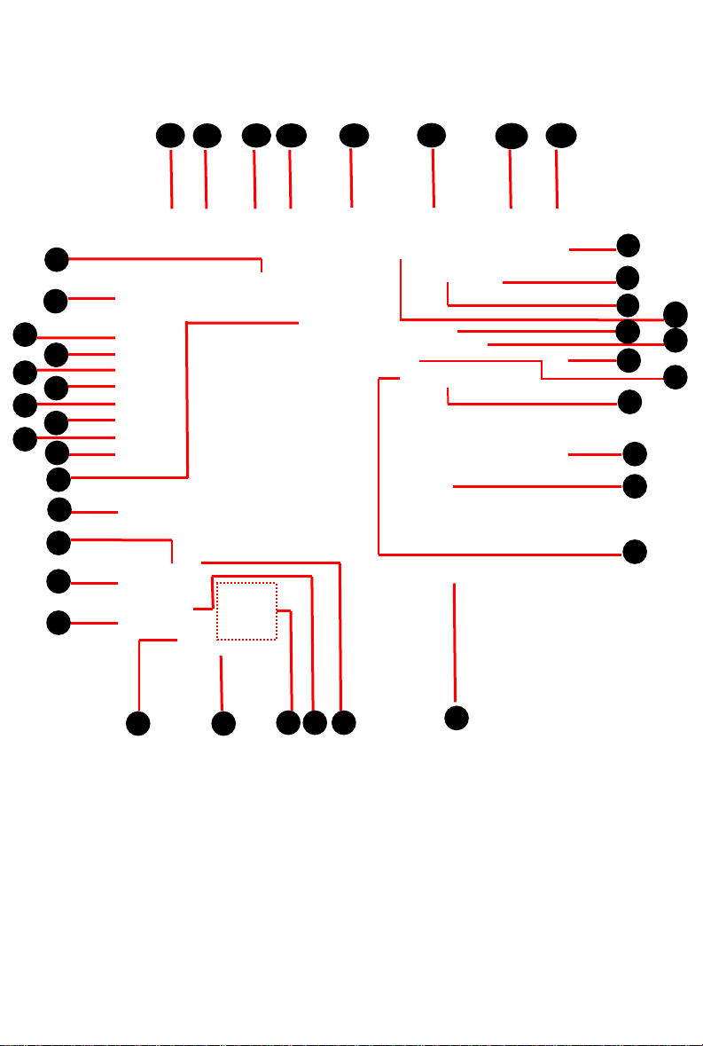
MNIC8CI Motherboard Layout
v
- 4 -
43
42
41
12

Item Code Description
1 AUDIO_JACK Audio jack
2 LPT Parallel port
3 RJ11 Cash drawer port
4 KB_MS1 PS/2 connector
5 USB_LAN1 USB ports and LAN por t
6 VGA1/COM2 VGA port and Serial por t
7 USB_LAN2 USB ports and LAN por t
8 DC_IN DC jack
9 DC_OUT 4 pin power connector
10 COM4 Serial cable connec tor
11 JCOM4 Serail port 5V,12 V, R I s elec t jum per
12 VGA2 VGA cable connect or
13 JRS1 RS232,RS422,RS 485 S el ect
Connector
14 LCDPWR_CON LCD power connect or
15 SYS_FAN System fan cable c onnec tor
16 BKLTEN_CON Back light inv erter jumper
17 LVDS LVDS connectors
18 CPU_FAN CPU fan cable connec tor
19 CPU Processor
20 INV_BRIG1 Inverter with box header
21 SO-DIMM DDR3 SO-DIMM slot
22 SATAPW2 SATA power connect or
23 SATAPW1 SATA power connect or
24 SATA1/2 SATA cable connect ors
25 SATA3 SATA 7+15 pins cable c onn ec tor
26 JFRONT Front panel connecotor
27 F_USB3 Front USB cable connec t or
28 F_USB2 Front USB cable connect or
29 BAT1 Battery s ock et
30 F_USB1 Front USB cable connec t or
31 MINI_CARD Mini PCI Express slot
32 COM6 Serial cable connector
33 JCOM6 Power COM sel ec t j umper
34 COM3 Serial cable connector
35 JCOM3 Power COM sel ec t j umper
36 COM5 Serial cable connector
37 JCOM5 Power COM sel ec t j umper
38 COM1 Serial cable connector
39 JCOM1 Power COM select jumper
40 F_AUDIO Front audio cable c onnec t or
41 KB_MS2 PS/2 cable connector
- 5 -

Chapter 1 Hardware Installation
1-1 Ins tallation Precautions
The motherboard contains numerous delicat e electronic circuits and components which can
become damaged as a result of electrostatic discharge (ESD). Prior to installation, carefully read the
user's manual and follow these procedures:
• Prior to installation, do not remove or break motherboard S/N (Serial Number) sticker or
warranty sticker provided by your dealer. These stickers are required for warranty validation.
• Always remove the AC power by unplugging the power cord from the power outlet before
installing or removing the motherboard or other hardware components.
• When connecting hardware components to the internal connectors on the motherboard,
make sure they are connected tightly and securely.
• When handling the motherboard, avoid touching any metal leads or connectors.
• It is best to wear an electrostatic discharge (ESD) wrist strap when handling electronic com-
ponents such as a motherboard, CPU or memory. If you do not have an ESD wrist strap,
keep your hands dry and first touch a metal object to eliminate static electricity.
• Prior to installing the motherboard, please have it on top of an antistatic pad or within an
electrostatic shielding container.
• Before unplugging the power supply cable from the motherboard, make sure the power supply has been turned off.
• Before turning on the power, make sure the power supply voltage has been set according to
the local voltage standard.
• Before using the product, please verify that all cables and power connectors of your hardware components are connected.
• To prevent damage to the motherboard, do not allow screws to come in contact with the
motherboard circuit or its components.
• Make sure there are no leftover screws or metal components placed on the motherboard or
within the computer casing.
• Do not place the computer system on an uneven surface
• Do not place the computer system in a high-temperature environment.
• Turning on the computer power during the installation process can lead to damage to sys-
tem components as well as physical harm to the user.
• If you are uncertain about any installation steps or have a problem related to the use of the
product, please consult a certified computer technician.
- 6 - Hardware Installation
.

1-2 Product Specifications
CPU Supports single Intel® D525 pr oc e s s or
Supports 1.8GHz
Chipset Intel
Memory 1 x SO-DIMM slot support DDR3 800
Audio Realtek® ALC269 codec
LAN 1 x Realtek
Expansion Slots 1 x mini PCI Express x1 slot
® ICH8M
Support up 2GB
High Definition Audio
2 channel
® RTL 8111Ed supports 10/100/1000 Mbps
Onboard Build in Intel
Graphics
Storage Interface 2 x SATA 3Gb/s connectors
1 x 7 pin & 15 pin SAT A c on n ector
USB Up to 10 USB 2.0/1.1 ports (4 on the back panel, 6 via the USB brackets
connected to the internal USB headers)
Internal 1 x 4 pin ATX 12V power connector
Connectors 2 x SATA 3Gb/s connectors
2 x SATA power connectors
1 x 7 pin & 15 pin SAT A c on n ector
1 x CPU fan header
1 x System fan header
4 x COM power select connector
1 x front panel header
1 x audio header
3 x USB 2.0 headers
1 x VGA header
1 x LVDS connector
Back Panel 1 x DC-in (12V) connector
Connector 4 x U SB 2.0 ports
2 x RJ-45 port
1 x VGA port
1 x COM ports
1 x Parallel port
1 x RJ-11 port
1 x Audio jack
1 x PS/2 connector
® ICH8M chipset
Hardware Instal lat ion - 7 -

Form Factor
* GIGABYTE r eserves the right to make any changes to the product s p ec i fic ations and produc t -related informatio n
without prior notice.
Mini ITX Form Factor; 6.75 inch x 6.75 inch
- 8 - Hardware Installation

1-3 Ins talling the Memory
Read the following g uidel ines bef or e y ou begi n t o ins tal l t he memor y :
• Make sure that the motherboard supports the memory. It is recommended that memory of the
same capacity, brand, speed, and chips be used.
(Go to GIGABYTE's website for the latest supported memory speeds and memory modules.)
• Always turn off the computer and unplug the power cord from the power outlet before installing
the memory t o prevent hardware damage.
• Memory modules have a foolproof design. A memory module can be installed in only one direc tion. If you are unable to insert the memory, switch the direction.
1-3-1 Installing a Memory
Before ins talling a memory module, make s ure to turn off the computer and unplug the power
cord from the power outlet to prev ent damage to the memory module.
Be s ure to i nstall DDR3 DIMMs on this motherboard.
Ins tall ati on Step:
Step 1. Align the memory with the DIMM module and insert the DIMM memory module into the DI M slot.
Please note that memory module has a foolproof insertion design. A memory module can be
install ed In onl y one di r ect ion.
Step 2. Push d own the memory a nd seat it firmly.
Step 3. Reverse the installat ion steps when you wish to rem ove the DIMM module.
1
Hardware Instal lat ion - 9 -
2
 Loading...