

Page 1

MN525RI
MN525MI
Intel® D525 Processor Motherboards
User's Manual
Rev. 1001
Page 2

Copyright
© 2010 GIGA-BYTE TECHNOLOGY CO., LTD. All rights reserved.
The trademarks mentioned in this manual are legally registered to their respective owners.
Disclaimer
Information in this manual is protected by copyright laws and is the property of GIGABYTE.
Changes to the specifications and features in this manual may be made by GIGABYTE
without prior notice. No part of this manual may be reproduced, copied, translated, transmitted,
or published in any form or by any means without GIGABYTE's prior written permission.
Documentation Classications
In order to assist in the use of this product, GIGABYTE provides the following types of documentations:
For quick set-up of the product, read the Quick Installation Guide included with the product.
For detailed product information, carefully read the User's Manual.
For product-related information, check on our website at:
http://www.gigabyte.com
Page 3

- 3 -
Table of Contents
MN525RI Motherboard Layout ........................................................................................4
Chapter 1 Hardware Installation .....................................................................................6
1-1 Installation Precautions .................................................................................... 6
1-2 ProductSpecications ...................................................................................... 7
1-3 Installing the Memory ....................................................................................... 9
1-3-1 DualChannelMemoryConguration .......................................................................9
1-3-2 Installing a Memory ...............................................................................................10
1-4 Back Panel Connectors .................................................................................. 11
1-5 Internal Connectors ........................................................................................ 12
Page 4
- 4 -
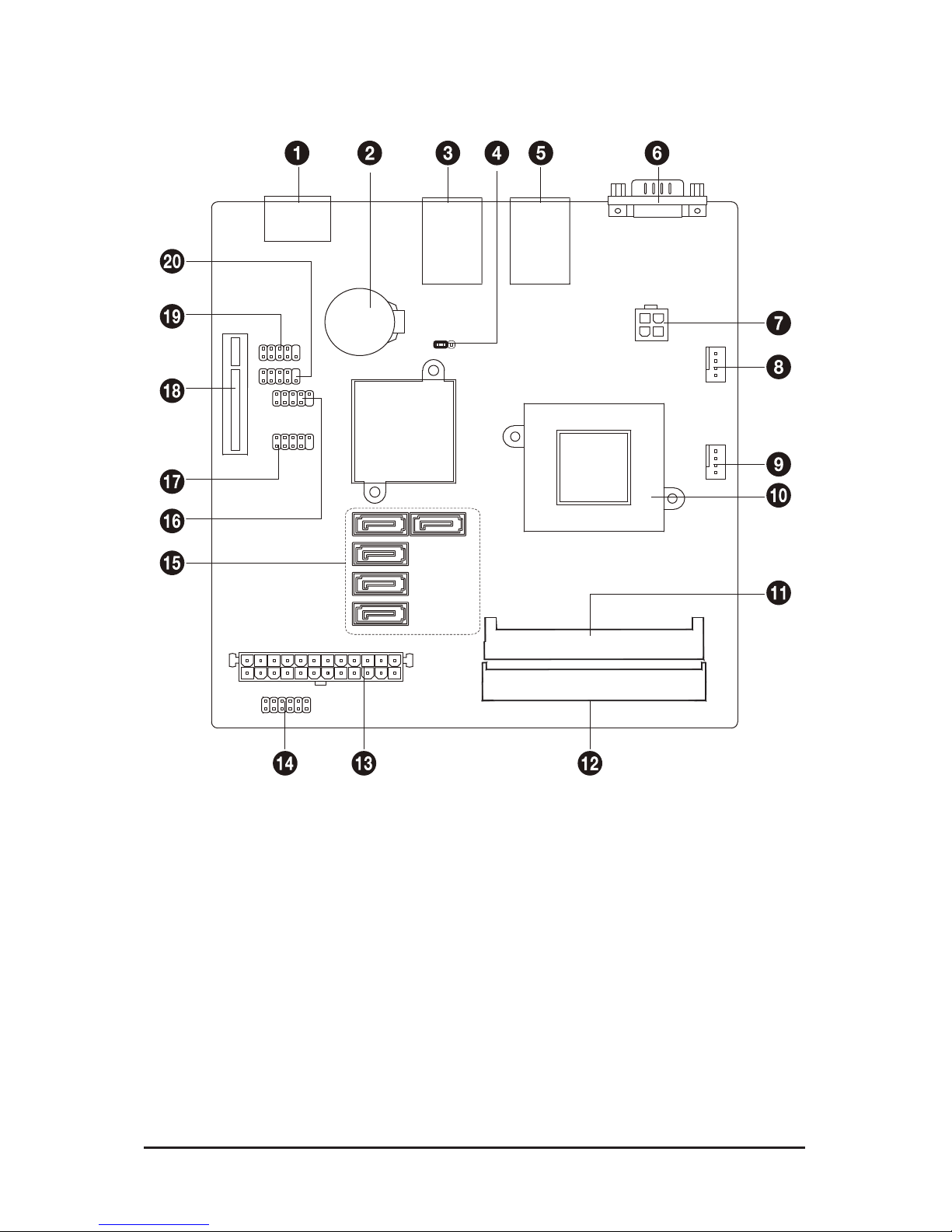
MN525RI Motherboard Layout
Page 5

- 5 -
Item Code Description
1 ESATA1 eSATA port
2 BATTERY Battery socket
3 USB_LAN1 USB ports and LAN port
4 CLR_CMOS Clear CMOS jumper
5 USB_LAN2 USB ports and LAN port
6 VGA VGA port
7 ATX_12V 4 pin power connector
8 FAN1 CPU fan cable connector
9 FAN2 System fan cable connector
10 CPU_HS Processor
11 SODIMMA DDR3 SO-DIMM slot
12 SODIMMB DDR3 SO-DIMM slot
13 ATX 24 pin power connector
14 F_PANEL Front panel connector
15 SATAII1~5 SATA cable connectors
16 F_USB2 Front USB cable connector
17 F_USB1 Front USB cable connector
18 PCIE4X PCI-E x4 slot
19 80H LPC80 connector
20 COM Serial cable connector
Page 6

- 6 - Hardware Installation
1-1 Installation Precautions
The motherboard contains numerous delicate electronic circuits and components which can
become damaged as a result of electrostatic discharge (ESD). Prior to installation, carefully read
the user's manual and follow these procedures:
• Prior to installation, do not remove or break motherboard S/N (Serial Number) sticker or
warranty sticker provided by your dealer. These stickers are required for warranty validation.
• Always remove the AC power by unplugging the power cord from the power outlet before
installing or removing the motherboard or other hardware components.
• When connecting hardware components to the internal connectors on the motherboard,
make sure they are connected tightly and securely.
• When handling the motherboard, avoid touching any metal leads or connectors.
• It is best to wear an electrostatic discharge (ESD) wrist strap when handling electronic com-
ponents such as a motherboard, CPU or memory. If you do not have an ESD wrist strap,
keep your hands dry and rst touch a metal object to eliminate static electricity.
• Prior to installing the motherboard, please have it on top of an antistatic pad or within an
electrostatic shielding container.
• Before unplugging the power supply cable from the motherboard, make sure the power sup-
ply has been turned off.
• Before turning on the power, make sure the power supply voltage has been set according to
the local voltage standard.
• Before using the product, please verify that all cables and power connectors of your hard-
ware components are connected.
• To prevent damage to the motherboard, do not allow screws to come in contact with the
motherboard circuit or its components.
• Make sure there are no leftover screws or metal components placed on the motherboard or
within the computer casing.
• Do not place the computer system on an uneven surface
.
• Do not place the computer system in a high-temperature environment.
• Turning on the computer power during the installation process can lead to damage to sys-
tem components as well as physical harm to the user.
• If you are uncertain about any installation steps or have a problem related to the use of the
product, please consult a certied computer technician.
Chapter 1 Hardware Installation
Page 7

Hardware Installation - 7 -
1-2 ProductSpecications
CPU Supports single Intel® D525 processor
Supports 1.8GHz
Chipset Intel® ICH9R
Memory 2 x SO-DIMM slot support DDR3 800/1066/1333
Support up 8GB
LAN 1 x Intel® 82574L supports 10/100/1000 Mbps
1 x Intel® 82567LM supports 10/100/1000 Mbps
Expansion Slots 1 x PCI Express x4 slot
Onboard
Graphics
Build in Intel® Integrated GMA3150
Storage Interface 5 x SATA 3Gb/s connectors
USB Up to 8 USB 2.0/1.1 ports (4 on the back panel, 4 via the USB brackets connected
to the internal USB headers)
Internal
Connectors
1 x 24 pin ATX power connector
1 x 4 pin ATX 12V power connector
5 x SATA 3Gb/s connectors
1 x CPU fan header
1 x system fan header
1 x serial cable connector
1 x front panel header
2 x USB 2.0 headers
Back Panel
Connectors
4 x USB 2.0 ports
2 x RJ-45 port
1 x VGA port
1 x eSATA port
I/O Controller iTE IT8721F chip
Hardware
Monitor
System voltage detection
CPU/System temperature detection
CPU/System fan speed control
* Whether the CPU/system fan speed control function is supported will depend on
the CPU/system cooler you install.
BIOS AMI BIOS
Page 8

- 8 - Hardware Installation
Form Factor Mini ITX Form Factor; 6.75 inch x 6.75 inch
* GIGABYTE reserves the right to make any changes to the product specications and product-related information
without prior notice.
Page 9

Hardware Installation - 9 -
1-3 Installing the Memory
Read the following guidelines before you begin to install the memory:
• Make sure that the motherboard supports the memory. It is recommended that memory of the
same capacity, brand, speed, and chips be used.
(
Go to GIGABYTE's website for the latest supported memory speeds and memory modules.
)
• Always turn off the computer and unplug the power cord from the power outlet before installing
the memory to prevent hardware damage.
• Memory modules have a foolproof design. A memory module can be installed in only one direction. If you are unable to insert the memory, switch the direction.
1-3-1 DualChannelMemoryConguration
This motherboard provides four DDR3 memory sockets and supports Dual Channel Technology. After the
memory is installed, the BIOS will automatically detect the specications and capacity of the memory. Enabling Dual Channel memory mode will double the original memory bandwidth.
The four DDR3 memory sockets are divided into two channels and each channel has two memory sockets as
following:
Channel A: SODIMMA
Channel B: DIMM1B, DIMM2B
SODIMMA
SODIMMB
Page 10

Hardware Installation - 10 -
1-3-2 Installing a Memory
Before installing a memory module, make sure to turn off the computer and unplug the power
cord from the power outlet to prevent damage to the memory module.
Be sure to install DDR3 DIMMs on this motherboard.
Installation Step:
Step 1. Align the memory with the DIMM module and insert the DIMM memory module into the DIM slot.
Please note that memory module has a foolproof insertion design. A memory module can be
installed In only one direction.
Step 2. Push down the memory and seat it rmly.
Step 3. Reverse the installation steps when you wish to remove the DIMM module.
2
1
Page 11

- 11 - Hardware Installation
1-4 Back Panel Connectors
Video Port
The video in port allows connect to video in, which can also apply to video loop thru function.
RJ-45 LAN Port
The Gigabit Ethernet LAN port provides Internet connection at up to 1 Gbps data rate. The following
describes the states of the LAN port LEDs.
USB 2.0/1.1 Port
The USB port supports the USB 2.0/1.1 specication. Use this port for USB devices such as a USB keyboard/mouse, USB printer, USB ash drive and etc.
USB 2.0/1.1 Port
The USB port supports the USB 2.0/1.1 specication. Use this port for USB devices such as a USB keyboard/mouse, USB printer, USB ash drive and etc.
eSTA Port
This connector supports SATA 3Gb/s specication. Use the port to connect an external SATA device or
a SATA port multiplier
• When removing the cable connected to a back panel connector, rst remove the cable from your
device and then remove it from the motherboard.
• When removing the cable, pull it straight out from the connector. Do not rock it side to side to
prevent an electrical short inside the cable connector.
Activity LED
Connection/
Speed LED
LAN Port
Activity LED:Connection/Speed LED:
State Description
Orange 1 Gbps data rate
Green 100 Mbps data rate
Off 10 Mbps data rate
State Description
Blinking Data transmission or receiving is occurring
Off No data transmission or receiving is occurring
Page 12

Hardware Installation - 12 -
1-5 Internal Connectors
1) ATX 7) F_USB1
2) ATX_12V 8) F_USB2
3) FAN1 9) COM
4) FAN2 10) 80H
5) SATAI I1~5 11) BAT
6) F_PANEL 12) CLR_CMOS
Read the following guidelines before connecting external devices:
• First make sure your devices are compliant with the connectors you wish to connect.
• Before installing the devices, be sure to turn off the devices and your computer. Unplug the
power cord from the power outlet to prevent damage to the devices.
• After installing the device and before turning on the computer, make sure the device cable has
been securely attached to the connector on the motherboard.
Page 13

Hardware Installation - 13 -
1
3
2
4
Pin No. Denition
1 GND
2 GND
3 +12V
4 +12V
1/2) ATX/ATX_12V (2x2 12V Power Connector and 2x12 Main Power Connector)
With the use of the power connector, the power supply can supply enough stable power to all the com-
ponents on the motherboard. Before connecting the power connector, rst make sure the power supply
is turned off and all devices are properly installed. The power connector possesses a foolproof design.
Connect the power supply cable to the power connector in the correct orientation. The 12V power connector mainly supplies power to the CPU. If the 12V power connector is not connected, the computer will
not start.
To meet expansion requirements, it is recommended that a power supply that can withstand high
power consumption be used (500W or greater). If a power supply is used that does not provide
the required power, the result can lead to an unstable or unbootable system.
13
1
24
12
ATX
PWR1:
Pin No. Denition
13 3.3V
14 -12V
15 GND
16 PS_ON (soft On/Off)
17 GND
18 GND
19 GND
20 -5V
21 +5V
22 +5V
23 +5V (Only for 2x12-pin ATX)
24 GND (Only for 2x12-pin ATX)
Pin No. Denition
1 3.3V
2 3.3V
3 GND
4 +5V
5 GND
6 +5V
7 GND
8 Power Good
9 5VSB (stand by +5V)
10 +12V
11 +12V (Only for 2x12-pin ATX)
12 3.3V (Only for 2x12-pin ATX)
Page 14

- 14 - Hardware Installation
2/3) FAN1/FAN2 (CPU Fan/System Fan Headers)
The motherboard has a 4-pin CPU fan header (FAN1), a 4-pin (FAN2) system fan headers. Most fan
headers possess a foolproof insertion design. When connecting a fan cable, be sure to connect it in the
correct orientation (the black connector wire is the ground wire). The motherboard supports CPU fan
speed control, which requires the use of a CPU fan with fan speed control design. For optimum heat dissipation, it is recommended that a system fan be installed inside the chassis.
• Be sure to connect fan cables to the fan headers to prevent your CPU and system from overheating. Overheating may result in damage to the CPU or the system may hang.
• These fan headers are not conguration jumper blocks. Do not place a jumper cap on the
headers.
FAN1 (CPU Fan):
FAN2 (System Fan):
Pin No. Denition
1 GND
2 +12V / Speed Control
3 Sense
4 Speed Control
Pin No. Denition
1 GND
2 +12V / Speed Control
3 Sense
4 Speed Control
1
11
2
12
DEBUG
PORT
FAN1
FAN1
FAN2
FAN2
5) F_PANEL (Front Panel Header)
Connect the power switch, reset switch, speaker, chassis intrusion switch/sensor and system status
indicator on the chassis to this header according to the pin assignments below. Note the positive and
negative pins before connecting the cables.
Pin No. Signal Name Denition
1 HD+ Hard Disk LED Signal (+)
2 MSG+ Message LED Signal (+)
3 HD- Hard Disk LED Signal (-)
4 MSG- Message LED Signal (-)
5 RST+ Reset Button (+)
6 PW+ Power Switch (+)
7 RST- Reset Button (-)
8 PW- Power Switch (-)
9 ACT+ LAN1 Act LED Signal (+)
10 ACT+ LAN 2Act LED Signal (+)
11 ACT- LAN1 Act LED Signal (-)
12 ACT- LAN2 Act LED Signal (-)
Page 15

- 15 - Hardware Installation
6) SATAII1/2/3/4/5 (SATA 3Gb/s Connectors)
The SATA connectors conform to SATA 3Gb/s standard and are compatible with SATA 1.5Gb/s standard.
Each SATA connector supports a single SATA device.
Pin No. Denition
1 GND
2 TXP
3 TXN
4 GND
5 RXN
6 RXP
7 GND
• A RAID 0 or RAID 1 conguration requires at least two hard drives. If more than two hard
drives are congured, the total number of hard drives must be an even number.
• A RAID 5 conguration requires at least three hard drives. (The total number of hard drives
does not have to be an even number.)
• A RAID 10 conguration requires four hard drives.
17
DEBUG
PORT
G.QBOFM
DEBUG
PORT
G.QBOFM
DEBUG
PORT
G.QBOFM
DEBUG
PORT
G.QBOFM
DEBUG
PORT
G.QBOFM
(Note) When a RAID conguration is built across the SATA 3Gb/s channels, the system performance of
the RAID conguration may vary depends on the devices are connected.
SATAII4
SATAII1SATAII5
SATAII3
SATAII2
7/8) F_USB1/F_USB2 (USB Headers)
The headers conform to USB 2.0/1.1 specication. Each USB header can provide two USB ports via an
optional USB bracket. For purchasing the optional USB bracket, please contact the local dealer.
Smart Card Reader
SPDIF
AUX_IN
CD_IN
Secure Gigital /
Memory Stick
Serial ATA
F_USB
F_1394
CPU_FAN
COMB
1 9
2 10
Pin No. Denition
1 Power (5V)
2 Power (5V)
3 USB DX-
4 USB DY-
5 USB DX+
6 USB DY+
7 GND
8 GND
9 No Pin
10 NC
When the system is in S4/S5 mode, only the USB ports routed to the F_USB1 header can
support the ON/OFF Charge function.
Page 16

- 16 - Hardware Installation
9) COM (Serial Port Header)
The COM header can provide one serial port via an optional COM port cable. For purchasing the
optional COM port cable, please contact the local dealer.
Pin No. Denition
1 NDCD-
2 NSIN
3 NSOUT
4 NDTR-
5 GND
6 NDSR-
7 NRTS-
8 NCTS-
9 NRI-
10 No Pin
SPDIF
AUX_IN
CD_IN
Secure Gigital /
Memory Stick
Serial ATA
CPU_FAN
SYS_FAN
PWR_FAN
NB_FAN
FDD
ATX
ATX_12V
1 9
2 10
SPDIF
AUX_IN
CD_IN
Secure Gigital /
Memory Stick
Serial ATA
CPU_FAN
SYS_FAN
PWR_FAN
NB_FAN
FDD
ATX
ATX_12V
1 9
2 10
10) 80H (Parallel Port Debug Card Header)
Pin No. Denition
1 Clock
2 GND
3 LPCFRAME#
4 PD0
5 LPCRST#
6 PD1
7 PD3
8 PD2
9 3.3V
10 No Pin
Page 17

- 17 - Hardware Installation
11) BATTERY (Battery)
The battery provides power to keep the values (such as BIOS congurations, date, and time information)
in the CMOS when the computer is turned off. Replace the battery when the battery voltage drops to a
low level, or the CMOS values may not be accurate or may be lost.
You may clear the CMOS values by removing the battery:
1. Turn off your computer and unplug the power cord.
2. Gently remove the battery from the battery holder and wait
for one minute. (Or use a metal object like a screwdriver
to touch the positive and negative terminals of the battery
holder, making them short for 5 seconds.)
3. Replace the battery.
4. Plug in the power cord and restart your computer.
• Always turn off your computer and unplug the power cord before replacing the battery.
• Replace the battery with an equivalent one. Danger of explosion if the battery is replaced with an incorrect model.
• Contact the place of purchase or local dealer if you are not able to replace the battery by yourself or uncertain about the bat-
tery model.
• When installing the battery, note the orientation of the positive side (+) and the negative side (-) of the battery (the positive
side should face up).
• Used batteries must be handled in accordance with local environmental regulations.
Page 18

Hardware Installation - 18 -
12) CLR_CMOS (Clearing CMOS Jumper)
Use this jumper to clear the CMOS values (e.g. date information and BIOS congurations) and reset
the CMOS values to factory defaults. To clear the CMOS values, place a jumper cap on the two pins to
temporarily short the two pins or use a metal object like a screwdriver to touch the two pins for a few
seconds.
1-2 Close: Normal operation (Default setting)
2-3 Close: Clear CMOS data)
• Always turn off your computer and unplug the power cord from the power outlet before clearing the CMOS
values.
• After clearing the CMOS values and before turning on your computer, be sure to remove the jumper cap from
the jumper. Failure to do so may cause damage to the motherboard.
• After system restart, go to BIOS Setup to load factory defaults (select Load Optimized Defaults) or manually
congure the BIOS settings (refer to Chapter 2, "BIOS Setup," for BIOS congurations).
1
1
 Loading...