


 Loading...
MD70-HB0
Dual LGA2011 sockets R3 motherboard for Intel® E5-2600 V3 series processors
User's Manual
Rev. 1201

Copyright
© 2014 GIGA-BYTE TECHNOLOGY CO., LTD. All rights reserved.
The trademarks mentioned in this manual are legally registered to their respective owners.
Disclaimer
Information in this manual is protected by copyright laws and is the property of GIGABYTE. Changes to the specifications and features in this manual may be made by GIGABYTE without prior notice. No part of this manual may be reproduced, copied, translated, transmitted, or published in any form or by any means without GIGABYTE's prior written permission.
Documentation Classifications
In order to assist in the use of this product, GIGABYTE provides the following types of documentations:
For detailed product information, carefully read the User's Manual.
For more information, visit our website at:
http://b2b.gigabyte.com
You are a professional?
Get an access to our complete source of sales, marketing & technical materials at:
http://reseller.b2b.gigabyte.com
https://www.facebook.com/gigabyteserver

Table of Contents
Box Contents.................................................................................................................... |
|
|
5 |
MD70-HB0 Motherboard Layout...................................................................................... |
6 |
||
Block Diagram.................................................................................................................. |
|
9 |
|
Chapter 1 Hardware Installation.................................................................................... |
10 |
||
1-1 |
Installation Precautions................................................................................... |
10 |
|
1-2 |
Product Specifications.................................................................................... |
11 |
|
1-3 Installing the CPU and CPU Cooler................................................................ |
13 |
||
|
1-3-1 |
Installing the CPU................................................................................................... |
13 |
|
1-3-2 |
Installing the CPU Cooler........................................................................................ |
16 |
1-4 |
Installing the Memory...................................................................................... |
17 |
|
|
1-4-1 |
Four Channel Memory Configuration...................................................................... |
17 |
|
1-4-2 |
Installing a Memory ................................................................................................ |
18 |
|
1-4-3 |
DIMM Population Table .......................................................................................... |
18 |
1-5 |
Back Panel Connectors.................................................................................. |
19 |
|
1-6 |
Internal Connectors........................................................................................ |
21 |
|
1-7 |
Jumper Settings.............................................................................................. |
37 |
|
Chapter 2 BIOS Setup................................................................................................... |
41 |
||
2-1 |
The Main Menu............................................................................................... |
43 |
|
2-2 |
Advanced Menu.............................................................................................. |
46 |
|
|
2-2-1 |
Serial Port Console Redirection.............................................................................. |
47 |
|
2-2-2 |
PCI Subsystem Settings......................................................................................... |
51 |
|
2-2-2-1 |
PCI Express Settings.............................................................................................. |
53 |
|
2-2-3 |
Network Stack......................................................................................................... |
55 |
|
2-2-4 |
CSM Configuration.................................................................................................. |
56 |
|
2-2-5 |
Post Report Configuration....................................................................................... |
58 |
|
2-2-6 |
Trusted Computing.................................................................................................. |
59 |
|
2-2-7 |
USB Configuration.................................................................................................. |
60 |
|
2-2-8 |
Chipset Configuration.............................................................................................. |
61 |
|
2-9 |
SIO Configuration.................................................................................................... |
62 |
|
2-2-10 |
iSCSI Configuration................................................................................................. |
65 |
2-3 Intel RC Setup Menu...................................................................................... |
66 |
||
|
2-3-1 |
Processor Configuration.......................................................................................... |
67 |
|
2-3-1-1 |
Pre-Socket Configuration........................................................................................ |
70 |
|
2-3-2 |
Advanced Power Management Configuration......................................................... |
72 |
|
2-3-2-1 |
CPU P State Control............................................................................................... |
73 |
|
2-3-2-2 |
CPU C State Control............................................................................................... |
74 |
|
|
|
|
|
|
- 3 - |
|

|
2-3-2-3 |
CPU T State Control................................................................................................ |
75 |
|
2-3-3 |
Common RefCode Configuration............................................................................ |
76 |
|
2-3-4 |
QPI Configuration.................................................................................................... |
77 |
|
2-3-5 |
Memory Configuration............................................................................................. |
79 |
|
2-3-5-1 |
Memory Topology.................................................................................................... |
81 |
|
2-3-5-2 |
Memory Thermal..................................................................................................... |
82 |
|
2-3-5-3 |
Memory Map........................................................................................................... |
83 |
|
2-3-5-4 |
Memory RAS Configuration.................................................................................... |
84 |
|
2-3-6 |
IIO Configuration..................................................................................................... |
85 |
|
2-3-6-1 |
IOAT Configuration.................................................................................................. |
86 |
|
2-3-6-2 |
Intel VT for Directed I/O (VT-d) .............................................................................. |
87 |
|
2-3-7 |
PCH Configuration ................................................................................................. |
88 |
|
2-3-7-1 |
PCH Devices........................................................................................................... |
89 |
|
2-3-7-2 |
PCH sSATA Configuration....................................................................................... |
90 |
|
2-3-7-2-1 SATA Mode Options.............................................................................................. |
93 |
|
|
2-3-7-3 |
PCH SATA Configuration......................................................................................... |
95 |
|
2-3-7-3-1 SATA Mode Options.............................................................................................. |
98 |
|
|
2-3-7-4 |
USB Configuration................................................................................................ |
100 |
|
2-3-8 |
Miscellaneous Configuration................................................................................. |
101 |
|
2-3-9 |
Server ME Configuration....................................................................................... |
102 |
|
2-3-10 |
Runtime Error Logging.......................................................................................... |
103 |
|
2-3-10-1Whea Setting......................................................................................................... |
104 |
|
|
2-3-10-2Memory Error Enabling......................................................................................... |
105 |
|
|
2-3-10-3PCI/PCI Error Enabling......................................................................................... |
106 |
|
2-4 |
Server Management Menu........................................................................... |
107 |
|
|
2-4-1 |
System Event Log................................................................................................. |
109 |
|
2-4-2 |
View FRU Information........................................................................................... |
110 |
|
2-4-3 |
BMC network configuration................................................................................... |
111 |
2-5 |
Security Menu............................................................................................... |
112 |
|
|
2-5-1 |
Secure Boot menu ............................................................................................... |
113 |
|
2-5-1-1 |
Key Management ................................................................................................ |
114 |
2-6 |
Boot Menu.................................................................................................... |
116 |
|
2-7 Save & Exit Menu......................................................................................... |
118 |
||
2-8 |
BIOS Beep Codes........................................................................................ |
120 |
|
2-9 |
BIOS Recovery Instruction........................................................................... |
121 |
|
Chapter 3 Appendix |
..................................................................................................... |
122 |
|
3-1 |
Regulatory Statements................................................................................. |
122 |
|
- 4 -
Box Contents
Motherboard
Driver CD
Two SATA cables
I/O Shield
•The box contents above are for reference only and the actual items shall depend on the product package you obtain. The box contents are subject to change without notice.
•The motherboard image is for reference only.
- 5 -
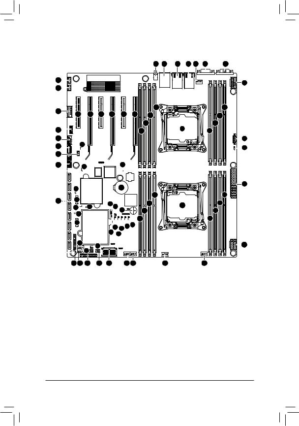
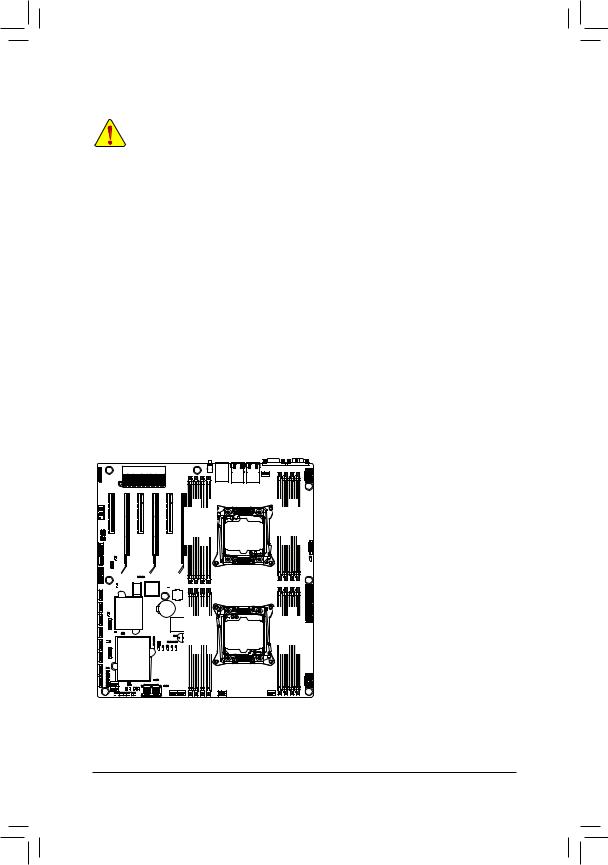
MD70-HB0 Motherboard Layout
|
|
|
|
|
|
|
1 |
2 |
3 |
4 |
5 |
6 |
7 |
62 |
|
|
|
|
|
|
|
|
|
|
|
|
8 |
61 |
|
|
|
|
|
|
|
|
|
|
|
|
|
|
|
|
|
|
|
|
|
|
|
|
|
|
|
60 |
|
|
|
|
|
|
70 |
|
|
|
|
|
9 |
63 |
65 |
66 |
67 |
68 |
69 |
71 |
|
|
|
|
|
10 |
|
|
|
|
|
|
|
||||||||
|
|
|
|
|
|
|
72 |
|
|
|
|
|
11 |
59 |
|
|
|
|
|
|
73 |
|
|
13 |
|
|
12 |
58 |
|
|
|
|
|
|
|
|
|
|
|
|
14 |
57 |
64 |
|
|
|
|
|
|
|
|
|
|
|
15 |
|
|
|
|
|
|
|
|
|
|
|
|
||
56 |
|
|
|
|
|
|
|
|
|
|
|
|
|
55 |
54 |
74 |
|
|
|
53U |
|
|
|
75 |
|
|
16 |
|
|
|
|
|
|
|
||
52 |
51 |
|
|
|
|
25 |
|
17 |
|
35 36 |
|
26 |
22 |
18 |
|||
|
50 |
49 |
|
|||||
|
76 |
19 |
||||||
|
48 |
|
|
|
27 |
|
||
|
|
|
|
|
28 |
|
20 |
|
|
47 |
|
|
|
|
|
||
|
|
33 31 30 |
29 |
|
|
|||
|
|
|
|
|
||||
|
|
|
34 |
32 |
|
|
|
|
|
46 |
|
41 |
|
|
|
|
21 |
|
|
42 |
|
|
|
|
||
|
|
|
|
|
|
|
|
|
45 44 |
43 |
40 |
39 |
38 37 |
24 |
23 |
- 6 -

Item |
Code |
Description |
|
1 |
SW_ID |
ID switch button |
|
2 |
USB3_MLAN1 |
BMC Management LAN port (top) / USB 3.0 ports |
|
(bottom) |
|||
|
|
||
3 |
LAN1 |
LAN1 port |
|
4 |
LAN2 |
LAN2 port |
|
5 |
CPU1_FAN |
CPU1 fan connector (for Secondary CPU) |
|
6 |
VGA1 |
VGA port |
|
7 |
COM1 |
Serial port |
|
8 |
P12V_AUX2 |
8 pin power connector (for secondary CPU) |
|
9 |
DIMM_P1_G0 |
Channel 3 slot 0 (for secondary CPU) |
|
10 |
DIMM_P1_G1 |
Channel 3 slot 1 (for secondary CPU) |
|
11 |
DIMM_P1_H0 |
Channel 4 slot 0 (for secondary CPU) |
|
12 |
DIMM_P1_H1 |
Channel 4 slot 1 (for secondary CPU) |
|
13 |
CPU1 |
Intel LGA2011 Socket R (Secondary CPU) |
|
14 |
PMBUS |
PMBus connector |
|
15 |
PMBUS_SEL |
PMbus select jumper |
|
16 |
ATX1 |
24 pin main power connector |
|
17 |
DIMM_P0_A0 |
Channel 1 slot 0 (for primary CPU) |
|
18 |
DIMM_P0_A1 |
Channel 1 slot 1 (for primary CPU) |
|
19 |
DIMM_P0_B0 |
Channel 2 slot 0 (for primary CPU) |
|
20 |
DIMM_P0_B1 |
Channel 2 slot 1 (for primary CPU) |
|
21 |
P12V_AUX1 |
8 pin power connector (for primary CPU) |
|
22 |
CPU0 |
Intel LGA2011 Socket R (Primary CPU) |
|
23 |
SYS_FAN5 |
System fan connector#5 |
|
24 |
CPU0_FAN |
CPU0 fan connector (for Primary CPU) |
|
25 |
DIMM_P0_D1 |
Channel 4 slot 1 (for primary CPU) |
|
26 |
DIMM_P0_D0 |
Channel 4 slot 0 (for primary CPU) |
|
27 |
DIMM_P0_C1 |
Channel 3 slot 1 (for primary CPU) |
|
28 |
DIMM_P0_C0 |
Channel 3 slot 0 (for primary CPU) |
|
29 |
ME_UPDATE |
ME update jumper |
|
30 |
BMC_FRB |
Force to Stop FRB Timer jumper |
|
31 |
ME_RCVR |
ME recovry jumper |
|
32 |
BIOS_WP |
BIOS write protect jumper |
|
33 |
BIOS_PWD |
Clearing Supervisor Password jumper |
|
34 |
BIOS_RCVR |
BIOS recovery jumper |
|
35 |
LSI_UART1 |
LSI UART header |
|
36 |
SW_RAID |
Intel Software RAID Key jumper |
|
37 |
SYS_FAN4 |
System fan connector#4 |
|
38 |
SYS_FAN3 |
System fan connector#3 |
|
39 |
MSAS_HD_1 |
HD Mini-SAS connector |
|
40 |
SATA_SGP |
SATA SGPIO header#1 |
- 7 -
41 |
IMR_KEY |
LSI RAID key header |
42 |
SSATA_SGP |
SAS SGPIO header#2 |
43 |
FP_1 |
Front panel header |
44 |
SYS_FAN1 |
System fan connector#1 |
45 |
BP_1 |
HDD back plane board header |
46 |
SYS_FAN2 |
System fan connector#2 |
47 |
SATA0 |
SATA 3 6Gb/s connector |
48 |
SATA_DOM0 |
SATA port 0 DOM support jumper |
49 |
CASE_OPEN |
Case open intrusion alert header |
50 |
LED5 |
LSI firmware readiness LED |
51 |
SATA1 |
SATA 3 6Gb/s connector |
52 |
SATA2/3/4/5/SSATA0/1/2/3 |
SATA 3 6Gb/s connectors |
53 |
SATA_DOM1 |
SATA port 1 DOM support jumper |
54 |
CLR_CMOS |
Clear CMOS jumper |
55 |
F_USB3 |
USB 3.0 header |
56 |
IPMB |
IPMB connector |
57 |
USB3_A |
Type A USB 3.0 connector |
58 |
F_USB2 |
USB 2.0 header |
59 |
TPM |
TPM module connector |
60 |
COM2 |
Serial port cable header |
61 |
LAN1_LED |
LAN #1 Active/Link connector |
62 |
LAN2_LED |
LAN #2 Active/Link connector |
63 |
PCIE_1 |
PCI Express x8 slot |
64 |
S3_MASK |
S3 Power On Select jumper |
65 |
PCIE_2 |
PCI Express x16 slot |
66 |
PCIE_3 |
PCI Express x8 slot |
67 |
PCIE_4 |
PCI Express x16 slot |
68 |
PCIE_5 |
PCI Express x8 slot |
69 |
PCIE_6 |
PCI Express x16 slot |
70 |
DIMM_P1_F1 |
Channel 3 slot 1 (for secondary CPU) |
71 |
DIMM_P1_F0 |
Channel 3 slot 0 (for secondary CPU) |
72 |
DIMM_P1_E1 |
Channel 4 slot 1 (for secondary CPU) |
73 |
DIMM_P1_E0 |
Channel 4 slot 0 (for secondary CPU) |
74 |
LED_BMC |
BMC firmware readiness LED |
75 |
BAT |
Battery socket |
76 |
BUZZER1 |
Buzzer |
CAUTION! If a SATA type hard drive is connected to the motherboard, please ensure the jumper is closed and set to 2-3 pins (Default setting), in order to reduce any risk of hard disk damage. Please refer to Page 37 for SATA_DOM0 and SATA_DOM1 jumper setting instruction.
- 8 -
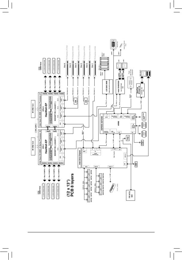
Block Diagram
- 9 -

Chapter 1 Hardware Installation
1-1 Installation Precautions
The motherboard contains numerous delicate electronic circuits and components which can become damaged as a result of electrostatic discharge (ESD). Prior to installation, carefully read the user's manual and follow these procedures:
•Prior to installation, do not remove or break motherboard S/N (Serial Number) sticker or warranty sticker provided by your dealer. These stickers are required for warranty validation.
•Always remove the AC power by unplugging the power cord from the power outlet before installing or removing the motherboard or other hardware components.
•When connecting hardware components to the internal connectors on the motherboard, make sure they are connected tightly and securely.
•When handling the motherboard, avoid touching any metal leads or connectors.
•It is best to wear an electrostatic discharge (ESD) wrist strap when handling electronic components such as a motherboard, CPU or memory. If you do not have an ESD wrist strap, keep your hands dry and first touch a metal object to eliminate static electricity.
•Prior to installing the motherboard, please have it on top of an antistatic pad or within an electrostatic shielding container.
•Before unplugging the power supply cable from the motherboard, make sure the power supply has been turned off.
•Before turning on the power, make sure the power supply voltage has been set according to the local voltage standard.
•Before using the product, please verify that all cables and power connectors of your hardware components are connected.
•To prevent damage to the motherboard, do not allow screws to come in contact with the motherboard circuit or its components.
•Make sure there are no leftover screws or metal components placed on the motherboard or within the computer casing.
•Do not place the computer system on an uneven surface.
•Do not place the computer system in a high-temperature environment.
•Turning on the computer power during the installation process can lead to damage to system components as well as physical harm to the user.
•If you are uncertain about any installation steps or have a problem related to the use of the product, please consult a certified computer technician.
Hardware Installation |
- 10 - |
1-2 |
Product Specifications |
||
|
|
|
|
|
CPU |
|
Support for Intel® Xeon® E5-2600 V3 series processors in the LGA2011 package |
|
|
|
L3 cache varies with CPU |
|
|
|
Supports Dual QuickPath Interconnect up to 9.6GT/s |
|
|
|
Enhanced Intel SpeedStep Technology (EIST) |
|
|
|
Support Intel Virtualization Technology (VT) |
|
Chipset |
|
Intel® C612 Express (Wellsburg) Chipset |
|
Memory |
|
16 x 1.2V DDR4 DIMM sockets supporting up to 2TB RDIMM of system memory |
|
|
|
Four channel memory architecture |
|
|
|
DDR4 1866MHz RDIMM memory modules |
|
|
|
DDR4 2133MHz LR-DIMM memory modules |
|
|
|
Support for ECC RDIMM/LRDIMM memory modules |
|
LAN |
|
Intel® X540 supports supports dual 10GbE LAN port |
|
|
|
Option Intel® I350 supports dual GbE LAN ports |
|
Expansion Slots |
|
1 x PCI Express x16 slot, running at x16 (Gen3/PCIE_6) |
|
|
|
1 x PCI Express x16 slot, running at x16 (Gen3/PCIE_4/The slot shares bandwidth |
|
|
|
with the PCIE_5 slot. When PCIE_5 slot is populated, the PCIE_4 will operate |
|
|
|
at x8 mode.) |
|
|
|
1 x PCI Express x16 slot, running at x16 (Gen3/PCIE_2/The slot shares bandwidth |
|
|
|
with the PCIE_3 slot. When PCIE_3 slot is populated, the PCIE_4 will operate |
|
|
|
at x8 mode.) |
|
|
|
3 x PCI Express x8 slots |
|
Onboard |
|
ASPEED® AST2400 supports 16MB DDR3 VRAM |
|
Graphics |
||
|
|
|
|
|
Storage Interface |
|
Intel® C612 Express controller |
|
|
|
10 x SATA3 6Gb/s connectors |
|
|
|
2 x HD Mini-SAS connectors |
|
|
|
Support for Intel RSTe 4.0 with SATA RAID 0, RAID 1, 10, 5 |
|
|
|
LSI® 3008 controller supports LSI RAID 0, 1, 1E |
|
USB |
|
Up to 5 USB 3.0 ports (1 Type A connector, 2 on the back panel, 2 additional |
|
|
ports via the USB brackets connected to the internal USB headers) |
|
|
|
|
|
|
|
|
|
- 11 - |
Hardware Installation |
Internal |
|
1 x 24-pin ATX main power connector |
Connectors |
|
2 x 8-pin ATX 12V power connector |
|
2 x HD Mini-SAS connectors |
|
|
10 x SATA3 6Gb/s connectors |
|
|
1 x PMBus header |
|
|
2 x CPU fan headers |
|
|
5 x System fan headers |
|
|
1 x Front panel header |
|
|
1 x HDD Back plane borad header |
|
|
1 x USB 3.0 header |
|
|
1 x TPM module connector |
|
|
1 x Serial port connector |
|
|
2 x SATA SPGIO headers |
|
|
1 x IPMB connector |
|
|
1 x Intel RAID key connector |
|
|
1 x LSI RAID key connector |
|
|
2 x LAN LED connectors |
|
Rear Panel I/O |
|
2 x USB 3.0 ports |
|
3 x RJ-45 ports (1 x 10/100/1000 dedicated management LAN port) |
|
|
1 x COM port |
|
|
|
1 x VGA port |
I/O Controller |
|
ASPEED® AST2400 BMC chip |
Hardware |
|
System voltage detection |
Monitor |
|
CPU/System temperature detection |
|
CPU/System fan speed detection |
|
|
CPU/System fan speed control |
|
|
|
* Whether the CPU/system fan speed control function is supported will depend on |
|
|
the CPU/system cooler you install. |
BIOS |
|
1 x 128 Mbit flash |
|
|
AMI BIOS |
Form Factor |
|
EATX Form Factor; 12.9 inch x 12 inch, 8 layers PCB |
* GIGABYTE reserves the right to make any changes to the product specifications and product-related information without prior notice.
Hardware Installation |
- 12 - |
1-3 Installing the CPU and CPU Cooler
Read the following guidelines before you begin to install the CPU:
•Make sure that the motherboard supports the CPU.
•Always turn off the computer and unplug the power cord from the power outlet before installing the CPU to prevent hardware damage.
•Locate the pin one of the CPU. The CPU cannot be inserted if oriented incorrectly. (Or you may locate the notches on both sides of the CPU and alignment keys on the CPU socket.)
•Apply an even and thin layer of thermal grease on the surface of the CPU.
•Do not turn on the computer if the CPU cooler is not installed, otherwise overheating and damage of the CPU may occur.
•Set the CPU host frequency in accordance with the CPU specifications. It is not recommended that the system bus frequency be set beyond hardware specifications since it does not meet the standard requirements for the peripherals. If you wish to set the frequency beyond the standard specifications, please do so according to your hardware specifications including the CPU, graphics card, memory, hard drive, etc.
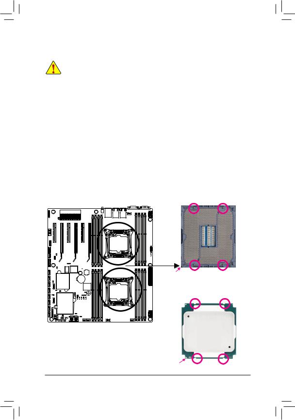
1-3-1 Installing the CPU
A. Locate the alignment keys on the motherboard CPU socket and the notches on the CPU.
Pin One Corner |
Alignment Key Alignment Key |
of the CPU Socket |
|
LGA2011 CPU
Notch Notch
Triangle Pin One Marking on the CPU Notch |
Notch |
- 13 - |
Hardware Installation |
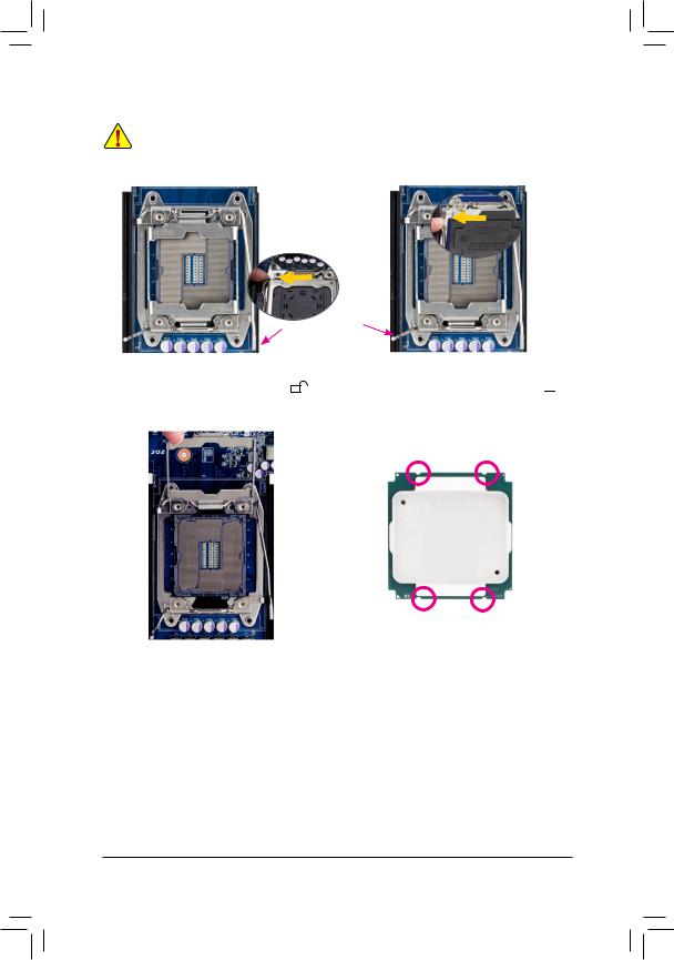
B. Follow the steps below to correctly install the CPU into the motherboard CPU socket.
•• Before installing the CPU, make sure to turn off the computer and unplug the power cord from the power outlet to prevent damage to the CPU.
•• To protect the socket contacts, do not remove the protective plastic cover unless the CPU is inserted into the CPU socket. Save the cover properly and replace it if the CPU is removed.
Lever A
Step 1: |
|
Push the lever closest to the "unlock" marking " |
" |
(below referred as lever A) down and away from the socket to release it.
Lever B
Step 2:
Push the lever closest to the "lock" marking " " (below referred as lever B) down and away from the socket. Then lift the lever.
Step 3:
Gently press lever A to allow the load plate to rise. Open the load plate. (Note: DO NOT touch the socket contacts after the load plate is opened.)
Step 4:
Hold the CPU with your thumb and index fingers. Align the CPU pin one marking (triangle) with the pin one corner of the CPU socket (or align the CPU notches with the socket alignment keys) and carefully insert the CPU into the socket vertically.
Hardware Installation |
- 14 - |
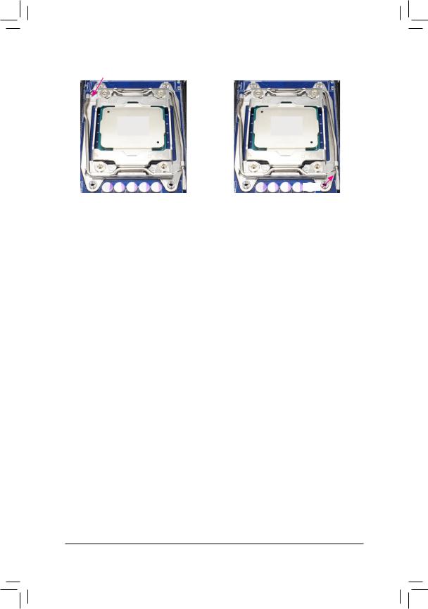
Lever B
Lever A
Step 5:
Once the CPU is properly inserted, carefully replace the load plate. Then secure lever B under its retention tab. The protective plastic cover may pop off from the load plate during the process of engaging the lever. Remove the cover. Save the cover properly and always replace it when the CPU is not installed.
Step 6:
Finally, secure lever A under its retention tab to complete the installation of the CPU.
- 15 - |
Hardware Installation |
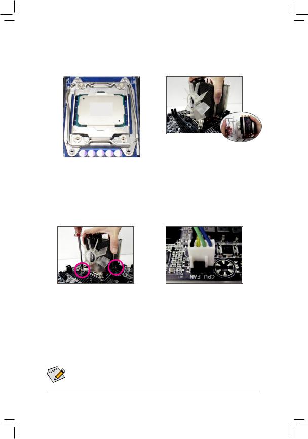
1-3-2 Installing the CPU Cooler
Refer to the steps below to correctly install the CPU cooler on the motherboard. (Actual installation process may differ depending the CPU cooler to be used. Refer to the user's manual for your CPU cooler.)
Step 1:
Apply an even and thin layer of thermal grease on the surface of the installed CPU.
Step 3:
Use one hand to hold the cooler and the other to tighten the screws in a diagonal sequence with a screw driver. Begin tightening a screw with a few turns and repeat with the screw diagonally opposite the one you just tightened. Then do the same to the other pair. Next, fully tighten the four screws.
Step 2:
Place the cooler atop the CPU, aligning the four mounting screws with the mounting holes on the ILM. (If your cooler has a fan grill which may cause interference when you tighten the screws, remove it first and replace it after tightening the screws.)
Step 4:
Finally, attach the power connector of the CPU cooler to the CPU fan header (CPU_FAN) on the motherboard.
Please pay more attention when removing the CPU cooler because the thermal grease/tape 
 between the CPU cooler and CPU may adhere to the CPU. Inadequately removing the CPU cooler
may damage the CPU.
Hardware Installation |
- 16 - |
1-4 Installing the Memory
Read the following guidelines before you begin to install the memory:
•Make sure that the motherboard supports the memory. It is recommended that memory of the same capacity, brand, speed, and chips be used.
•Always turn off the computer and unplug the power cord from the power outlet before installing the memory to prevent hardware damage.
•Memory modules have a foolproof design. A memory module can be installed in only one direction. If you are unable to insert the memory, switch the direction.
1-4-1 Four Channel Memory Configuration
This motherboard provides sixteen DDR4 memory sockets and supports Four Channel Technology. After the memory is installed, the BIOS will automatically detect the specifications and capacity of the memory.
Enabling Four Channel memory mode will be four times of the original memory bandwidth.
The four DDR4 memory sockets are divided into four channels each channel has two memory sockets as following:
Channel 1: DIMM_P0_A0/DIMM_P0_A1 (For pimary CPU)/ DIMM_P1_E0/DIMM_P1_E1 (For secondary CPU)
Channel 2: DIMM_P0_B0/DIMM_P0_B1 (For pimary CPU) DIMM_P1_F0/DIMM_P1_F1 (For secondary CPU)
Channel 3: DIMM_P0_C0/DIMM_P0_C1 (For pimary CPU) DIMM_P1_G0/DIMM_P1_G1 (For secondary CPU)
Channel 4: DIMM_P0_D0/DIMM_P0_D1 (For pimary CPU) DIMM_P1_H0/DIMM_P1_H1 (For secondary CPU)
DIMM P1 E0 DIMM P1 E1 DIMM P1 F0 DIMM P1 F1 |
DIMM P1 H1 DIMM P1 H0 DIMM P1 G1 DIMM P1 G0 |
DIMM P0 C0 DIMM P0 C1 DIMM P0 D0 DIMM P0 D1 |
DIMM P0 B1 DIMM P0 B0 DIMM P0 A1 DIMM P0 A0 |
Due to CPU limitations, read the following guidelines before installing the memory in Four Channel mode.
1.Four Channel mode cannot be enabled if only one DDR3 memory module is installed.
2.When enabling Four Channel mode with two or four memory modules, it is recommended that memory of the same capacity, brand, speed, and chips be used for optimum performance.
- 17 - |
Hardware Installation |
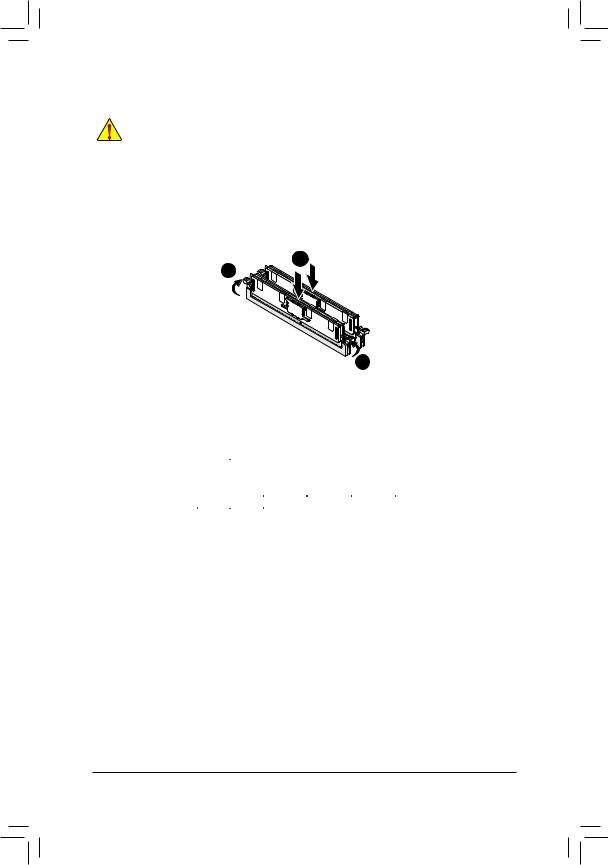
1-4-2 |
Installing a Memory |
|
Before installing a memory module, make sure to turn off the computer and unplug the power |
|
cord from the power outlet to prevent damage to the memory module. |
|
Be sure to install DDR3 DIMMs on this motherboard. |
Installation Step: |
|
Step 1. |
Insert the DIMM memory module vertically into the DIMM slot, and push it down. |
Step 2. |
Close the plastic clip at both edges of the DIMM slots to lock the DIMM module. |
Note: |
For dual-channel operation, DIMMs must be installed in matched pairs. |
Step 3. |
Reverse the installation steps when you wish to remove the DIMM module. |
|
1 |
|
2 |
2
1-4-3 DIMM Population Table
Two Slots Channel RDIMM Population Configuration Within a Channel
|
|
|
Speed (MT/s); |
|
|
Ranks Per |
Slot Per Channel (SPC) and DIMM Per Channel (DPC) |
||
Type |
DIMM and |
|
|
|
|
Data Width |
1 Slot Per Channel |
2 Slot Per Channel |
|
|
|
|||
|
|
1DPC |
1DPC |
2DPC |
RDIMM |
SRx4 |
2133 |
2133 |
1866 |
|
|
|
|
|
RDIMM |
SRx8 |
2133 |
2133 |
1866 |
|
|
|
|
|
RDIMM |
DRx8 |
2133 |
2133 |
1866 |
|
|
|
|
|
RDIMM |
DRx4 |
2133 |
2133 |
2133 |
|
|
|
|
|
LRDIMM |
QRx4 |
2133 |
2133 |
2133 |
|
|
|
|
|
Hardware Installation |
- 18 - |
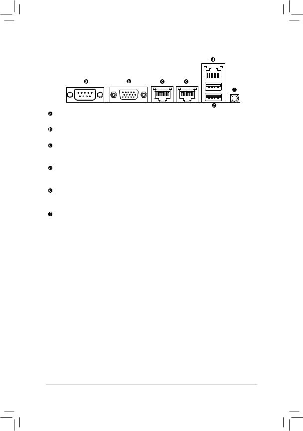
1-5 Back Panel Connectors
Serial Port
Connects to serial-based mouse or data processing devices.
Video Port
The video in port allows connect to video in, which can also apply to video loop thru function.
RJ-45 LAN Ports (10 Gigabit Ethernet LAN Ports)
The Gigabit Ethernet LAN port provides Internet connection at up to 10 Gbps data rate. The following describes the states of the LAN port LEDs.
KVM Server Management 10/100/1000 LAN Port (Dedicated LAN Port)
The LAN port provides Internet connection with data transfer speeds of 10/100/1000Mbps. This port is the decated LAN port for server management.
USB 3.0 Port
The USB port supports the USB 3.0 specification. Use this port for USB devices such as a USB keyboard/mouse, USB printer, USB flash drive and etc.
ID Switch Button
This button provide the selected unit idenfication function.
- 19 - |
Hardware Installation |
|
|
|
|
|
|
|
|
|
Link |
|
Speed LED: |
|
|
|
Link/Activity LED: |
||||||||
Speed LED |
|
|
|
Activity LED |
|
|
|
|
|
|
|
|
|||||||||||
|
|
|
|
State |
Description |
|
State |
Description |
|||||||||||||||
|
|
|
|
|
|
|
|
|
|
|
|
|
|
|
|
|
Yellow On |
1 Gbps data rate |
|
On |
Link between system and network or no |
||
|
|
|
|
|
|
|
|
|
|
|
|
|
|
|
|
|
Yellow Blink |
Identify 1 Gbps data |
|
|
access |
||
|
|
|
|
|
|
|
|
|
|
|
|
|
|
|
|
|
|
|
rate |
|
Blinking |
Data transmission or receiving is occurring |
|
|
|
|
|
|
|
|
|
|
|
|
|
|
|
|
|
|
Green On |
100 Mbps data rate |
|
Off |
No data transmission or receiving is occurring |
||
10/100/1000 LAN Port |
|||||||||||||||||||||||
|
|
|
|
|
|
|
|
|
|
|
|
|
|
|
|
|
Green Blink |
Identify 100 Mbps data |
|
|
|
||
|
|
|
|
|
|
|
|
|
|
|
|
|
|
|
|
|
|
|
rate |
|
|
|
|
|
|
|
|
|
|
|
|
|
|
|
|
|
|
|
|
|
Off |
10 Mbps data rate |
|
|
|
||
|
|
|
|
|
|
|
|
|
|
|
|
|
|
|
|
Speed LED: |
|
|
|
Link/Activity LED: |
|||
|
|
|
|
|
|
|
|
|
|
|
|
|
|
|
|
|
State |
|
Description |
|
|
State |
Description |
|
|
|
|
|
|
|
|
|
|
|
|
|
|
|
|
|
Green On |
|
10 Gbps data rate |
|
|
On |
Link between system and network or no |
|
|
|
|
|
|
|
|
|
|
|
|
|
|
|
|
|
Green Blink |
|
Identify 10 Gbps data |
|
|
|
access |
Speed LED |
|
|
|
Link |
|
|
|
rate |
|
|
Blinking |
Data transmission or receiving is occurring |
|||||||||||
|
|
|
|
Yellow On |
|
1 Gbps data rate |
|
|
Off |
No data transmission or receiving is occurring |
|||||||||||||
|
|
|
Activity LED |
|
|
|
|
||||||||||||||||
|
|
|
|
|
|
|
|
|
|
|
|
|
|||||||||||
|
|
|
|
|
|
|
|
|
|
Yellow Blink |
|
Identify 1 Gbps data |
|
|
|
|
|||||||
|
|
|
|
|
|
|
|
|
|
|
|
|
|
|
|
|
|
|
|
|
|
||
1000/10G LAN Port |
|
|
|
rate |
|
|
|
|
|||||||||||||||
|
|
|
|
|
|
|
|
|
|
|
|
|
|
|
|
|
Off |
|
100 Mbps data rate |
|
|
|
|
•When removing the cable connected to a back panel connector, first remove the cable from your device and then remove it from the motherboard.
•When removing the cable, pull it straight out from the connector. Do not rock it side to side to prevent an electrical short inside the cable connector.
Hardware Installation |
- 20 - |
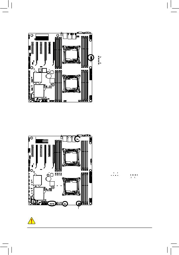
1-6 Internal Connectors
31
24


23

 22
22


21
20 |
29 |
14  13
13
30 |
28 |
12 |
|
7 |
17 |
|
|
19 8 |
18 |
32
27 25
26 |
|
|
|
|
16 |
15 |
9 |
10 |
5 |
6
3
4 |
1
2
11 |
1) |
ATX1 |
17) |
SATA_SGP2 |
2) |
P12V_AUX1 |
18) |
FP_1 |
3) |
P12V_AUX2 |
19) |
BP_1 |
4) |
PMBUS |
20) |
F_USB1 |
5) |
CPU0_FAN (for primary CPU) |
21) |
IPMB |
6) |
CPU1_FAN (for seconary CPU) |
22) |
F_USB2 |
7) |
SYS_FAN1 (System Fan) |
23) |
TPM |
8) |
SYS_FAN2 (System Fan) |
24) |
COM2 |
9) |
SYS_FAN3 (System Fan) |
25) |
SW_RAID |
10) |
SYS_FAN4 (System Fan) |
26) |
IMR_KEY |
11) |
SYS_FAN5 (System Fan) |
27) |
LSI_UART1 |
12) |
SATA0 |
28) |
CASE_OPEN |
13) |
SATA1 |
29) |
LED_BMC |
14) |
SATA/2/3/4/5/SSATA0/1/2/3 |
30) |
LED |
15) |
MSAS_HD |
31) |
LAN1_LED (buttom)/LAN2_LED (top) |
16) |
SATA_SGP1 |
32) |
BAT |
|
|
- 21 - |
Hardware Installation |
Read the following guidelines before connecting external devices:
•First make sure your devices are compliant with the connectors you wish to connect.
•Before installing the devices, be sure to turn off the devices and your computer. Unplug the power cord from the power outlet to prevent damage to the devices.
•After installing the device and before turning on the computer, make sure the device cable has been securely attached to the connector on the motherboard.
Hardware Installation |
- 22 - |
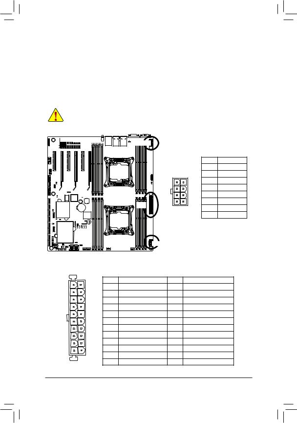
1/2/3) ATX1/P12V_AUX1/P12V_AUX2
(2x4 12V Power Connector and 2x12 Main Power Connector)
With the use of the power connector, the power supply can supply enough stable power to all the components on the motherboard. Before connecting the power connector, first make sure the power supply is turned off and all devices are properly installed. The power connector possesses a foolproof design. Connect the power supply cable to the power connector in the correct orientation. The 12V power connector mainly supplies power to the CPU. If the 12V power connector is not connected, the computer will not start.
•To meet expansion requirements, it is recommended that a power supply that can withstand high power consumption be used (500W or greater). If a power supply is used that does not provide the required power, the result can lead to an unstable or unbootable system.


 P12V_AUX2
|
|
|
|
P12V_AUX1 |
Pin No. |
Definition |
||
|
|
|
|
1 |
GND |
|||
|
|
|
|
P12V_AUX2 |
||||
|
|
|
|
5 |
1 |
|
2 |
GND |
|
|
|
|
|
|
|
3 |
GND |
|
|
|
|
|
|
|
4 |
GND |
|
|
|
|
|
|
|
5 |
+12V |
|
|
|
ATX1 |
|
|
|
6 |
+12V |
|
|
|
8 |
4 |
|
7 |
+12V |
|
|
|
|
|
|
||||
|
|
|
|
|
|
|
8 |
+12V |
|
|
|
P12V_AUX1 |
|
|
|
|
|
ATX1 |
|
|
|
|
|
|
|
|
13 |
1 |
ATX1 |
|
|
|
|
|
|
|
Pin No. |
Definition |
Pin No. |
|
Definition |
|
|
|
|
|
|
|
|
||||
|
|
1 |
3.3V |
13 |
|
3.3V |
|
|
|
|
2 |
3.3V |
14 |
|
-12V |
|
|
|
|
3 |
GND |
15 |
|
GND |
|
|
|
|
4 |
+5V |
16 |
|
PS_ON |
|
|
|
|
5 |
GND |
17 |
|
GND |
|
|
|
|
6 |
+5V |
18 |
|
GND |
|
|
|
|
7 |
GND |
19 |
|
GND |
|
|
|
|
8 |
Power Good |
20 |
|
-5V |
|
|
|
|
9 |
5VSB (stand by +5V) |
21 |
|
+5V |
|
|
|
|
10 |
+12V |
22 |
|
+5V |
|
|
|
12 |
11 |
+12V |
23 |
|
+5V |
|
|
24 |
12 |
3.3V |
24 |
|
GND |
|
|
|
|
|
|
|
|||||
- 23 - |
Hardware Installation |
4) PMBUS (PMBus connector)
5 |
|
|
|
Pin No. |
Definition |
|
|
|
1 |
PMBus CLK |
|
|
|
|
|
||
|
|
|
|
2 |
PMBus DATA |
|
|
|
|
3 |
PMBus Alert |
1 |
|
|
|
4 |
GND |
|
|
|
|
5 |
3.3V Sense |
|
|
|
|
|
|
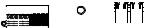
5/6/7/8/9/10/11) CPU_FAN0/CPU_FAN1/SYS_FAN1/SYS_FAN2/SYS_FAN3/SYS_FAN4/ SYS_FAN5 (CPU Fan/System Fan Headers)
The motherboard has two 4-pin CPU fan headers, and four 4-pin system fan headers. Most fan
headers possess a foolproof insertion design. When connecting a fan cable, be sure to connect it in the correct orientation (the black connector wire is the ground wire). The motherboard supports CPU fan speed control, which requires the use of a CPU fan with fan speed control design. For optimum heat dissipation, it is recommended that a system fan be installed inside the chassis.


 CPU1_FAN
|
|
|
|
|
|
|
|
|
|
|
|
|
|
|
|
|
|
|
|
|
|
|
|
|
|
|
|
|
|
|
|
|
|
|
|
|
|
|
|
|
|
|
|
|
|
|
|
|
|
|
|
|
|
|
|
|
|
|
|
|
|
|
|
|
|
|
|
|
|
|
|
|
|
|
|
|
|
|
|
|
|
|
|
|
|
|
|
|
|
|
|
|
|
|
|
|
|
|
|
|
|
|
|
|
|
|
|
|
|
|
|
|
|
|
|
|
|
|
|
|
|
|
|
|
|
|
|
|
|
|
|
|
|
|
|
|
|
|
|
|
|
|
|
|
|
|
|
|
|
|
|
|
|
|
|
|
|
|
|
|
|
|
|
|
|
|
|
|
|
|
|
|
|
|
|
|
|
|
|
|
|
|
|
|
|
|
|
|
|
|
|
|
|
|
|
|
|
|
|
|
|
|
|
|
|
|
|
|
|
|
|
|
|
|
|
|
|
|
|
|
|
|
|
|
SYS_FAN2 |
|
|
|
SYS_FAN3 |
|
|
|
|||||||
|
|
|
SYS_FAN1 |
SYS_FAN4 CPU0 |
_FAN |
|||||||||
|
|
|
|
SYS_FAN1 |
|||
|
|
|
|
SYS_FAN2 |
|||
CPU0_FAN |
SYS_FAN3 |
||||||
SYS_FAN4 |
|||||||
CPU1_FAN |
SYS_FAN5 |
||||||
|
1 |
1 |
|
|
|
||
|
|
|
|
||||
|
|
|
|
|
|
|
|
|
|
|
|
|
|
|
|
Pin No. |
Definition |
1 |
GND |
2 |
+12V |
3 |
Sense |
4 |
Speed Control |
SYS_FAN5
•Be sure to connect fan cables to the fan headers to prevent your CPU and system from overheating. Overheating may result in damage to the CPU or the system may hang.
•These fan headers are not configuration jumper blocks. Do not place a jumper cap on the headers.
Hardware Installation |
- 24 - |

12/13) SATA0/SATA1 (SATA 6Gb/s Connectors/SATA4/5 Support SATA DOM Function)
The SATA connectors conform to SATA 6Gb/s standard and are compatible with SATA 3Gb/s and
1.5Gb/s standard. Each SATA connector supports a single SATA device. Please see page 35 for SATA DOM jumper setting.
7
|
|
|
1 |
|
|
|
Normal Mode: |
SATA DOM Mode: |
|||
|
Pin No. |
Definition |
Pin No. |
Definition |
|
|
1 |
GND |
1 |
GND |
|
|
2 |
TXP |
2 |
TXP |
|
|
3 |
TXN |
3 |
TXN |
|
SATA1 |
4 |
GND |
4 |
GND |
|
5 |
RXN |
5 |
RXN |
||
|
|||||
SATA0 |
6 |
RXP |
6 |
RXP |
|
7 |
GND |
7 |
P5V |
||
|
|||||
14)SATA/2/3/4/5SSATA0/1/2/3 (SATA 6Gb/s Connectors
The SATA connectors conform to SATA 6Gb/s standard and are compatible with SATA 3Gb/s and 1.5Gb/s standard. Each SATA connector supports a single SATA device.
|
7 |
Pin No. |
Definition |
|
|
1 |
GND |
||
|
|
2 |
TXP |
|
|
|
3 |
TXN |
|
|
|
4 |
GND |
|
SSATA3 |
1 |
5 |
RXN |
|
6 |
RXP |
|||
SSATA2 |
|
|||
|
7 |
GND |
||
SSATA1 |
|
|||
|
|
|
||
SSATA0 |
|
|
|
|
SATA5 |
|
|
|
|
SATA4 |
|
|
|
|
SATA3 |
|
|
|
|
SATA2 |
|
|
|
• A RAID 0 or RAID 1 configuration requires at least two hard drives. If more than two hard drives are configured, the total number of hard drives must be an even number.
• A RAID 10 configuration requires four hard drives.
(Note) When a RAID configuration is built across the SATA 6Gb/s channels, the system performance of
the RAID configuration may vary depends on the devices are connected. |
|
- 25 - |
Hardware Installation |
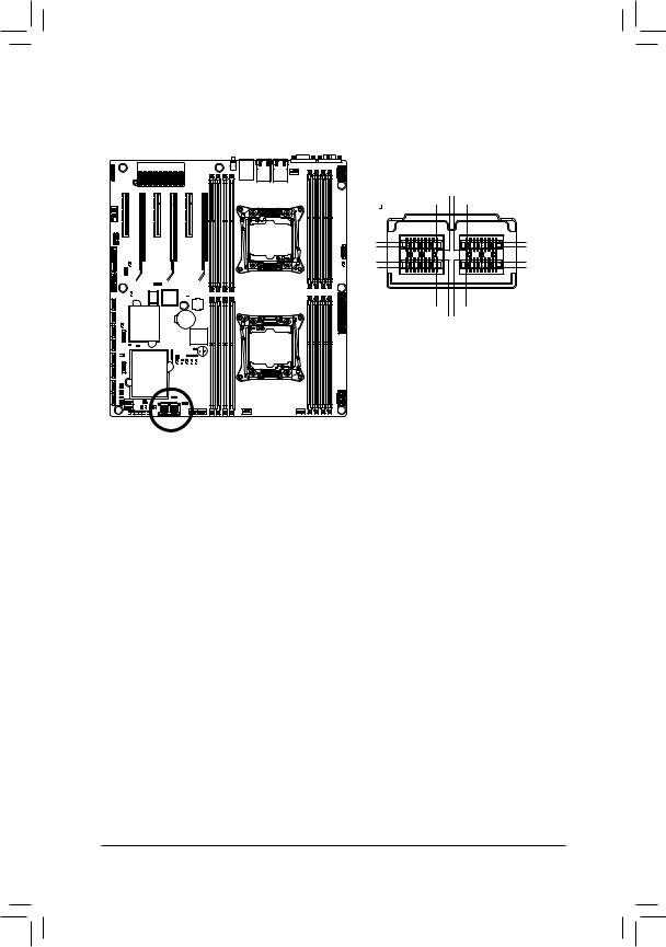
15)MSAS_HD (HD Mini-SAS connectors)
HD Mini-SAS (High Density SFF-8644) is the next-generation SAS high-density and high-speed IO interface. HD Mini-SAS is in the SAS 2.1 standard, meets the 6Gb/s SAS specification.
|
1D9 1C9 0D10C1 |
1D1 |
0D9 |
1C1 |
0C9 |
1B1 |
0B9 |
1A1 |
0A9 |
1A9 |
0A1 |
0B9 |
0B1 |
Pin No. |
Definition |
Pin No. |
Definition |
Pin No. |
Definition |
Pin No. |
Definition |
0A1 |
NC |
0C1 |
GND |
1A1 |
GND |
1C1 |
GND |
0A2 |
SGPIO_CLOCK0 |
0C2 |
GND |
1A2 |
SGPIO_CLOCK1 |
1C2 |
GND |
0A3 |
GND |
0C3 |
GND |
1A3 |
GND |
1C3 |
GND |
0A4 |
RXP1 |
0C4 |
TXP1 |
1A4 |
RXP5 |
1C4 |
TXP5 |
0A5 |
RXN1 |
0C5 |
TXN1 |
1A5 |
RXN5 |
1C5 |
TXN5 |
0A6 |
GND |
0C6 |
GND |
1A6 |
GND |
1C6 |
GND |
0A7 |
RXP3 |
0C7 |
TXP3 |
1A7 |
RXP7 |
1C7 |
TXP7 |
0A8 |
RXN3 |
0C8 |
TXN3 |
1A8 |
RXN7 |
1C8 |
TXN7 |
0A9 |
GND |
0C9 |
GND |
1A9 |
GND |
1C9 |
GND |
0B1 |
GND |
0D1 |
SGPIO_DATAIN0 |
1B1 |
GND |
1D1 |
SGPIO_DATAIN1 |
0B2 |
SGPIO_LOAD0 |
0D2 |
NC |
1B2 |
SGPIO_LOAD1 |
1D2 |
GND |
0B3 |
GND |
0D3 |
GND |
1B3 |
GND |
1D3 |
GND |
0B4 |
RXP0 |
0D4 |
TXP0 |
1B4 |
RXP4 |
1D4 |
TXP4 |
0B5 |
RXN0 |
0D5 |
TXN0 |
1B5 |
RXN4 |
1D5 |
TXN4 |
0B6 |
GND |
0D6 |
GND |
1B6 |
GND |
1D6 |
GND |
0B7 |
RXP2 |
0D7 |
TXP2 |
1B7 |
RXP6 |
1D7 |
TXP6 |
0B8 |
RXN2 |
0D8 |
TXN2 |
1B8 |
RXN6 |
1D8 |
TXN6 |
0B9 |
GND |
0D9 |
GND |
1B9 |
GND |
1D9 |
GND |
Hardware Installation |
- 26 - |
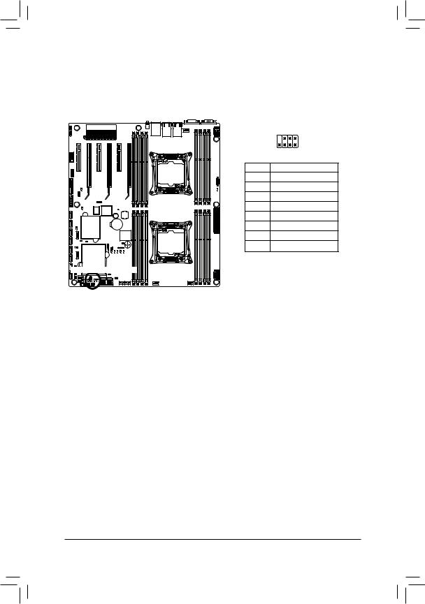
16/17) SATA_SGP/SSATA_SGP (SAS SGPIO Headers)
SGPIO stands for Serial General Purpose Input/Output which is a 4-signal (or 4-wire) bus used between a Host Bus Adapter (HBA) and a backplane. Out of the 4 signals, 3 are driven by the HBA and 1 is driven by the backplane. Typically, the HBA is a storage controller located inside a server, desktop, rack or workstation computer that interfaces with Hard disk drives (HDDs) to store and retrieve data.
2 |
8 |
1 |
7 |
Pin No. |
Definition |
1 |
DATAIN |
2 |
No Pin |
3 |
DATAOUT |
4 |
GND |
5 |
GND |
6 |
LOAD |
7 |
NC |
8 |
CLOCK |

 SSATA_SGP SATA_SGP
- 27 - |
Hardware Installation |
18)FP_1 (Front Panel Header)
Connect the power switch, reset switch, chassis intrusion switch/sensor and system status indicator on the chassis to this header according to the pin assignments below. Note the positive and negative pins before connecting the cables.
2 |
24 |
1 |
23 |
Pin No. |
Signal Name |
Definition |
1 |
PWLED+ |
Power LED Signal anode (+) |
2 |
5VSB |
5V Stanndby Power |
3 |
NC |
No Pin |
4 |
ID_LED+ |
ID LED Signal anode (+) |
5 |
PWLED- |
Power LED Signal cathode(-) |
6 |
ID_LED- |
ID LED Signal cathode(-) |
7 |
HD+ |
Hard Disk LED Signal anode (+) |
8 |
SYS_LED+ |
System Front board LED Signal anode (+) |
9 |
HD- |
Hard Disk LED Signal cathode(-) |
10 |
SYS_LED- |
System Status LED Signal cathode(-) |
11 |
PWR_BTN |
Power Button Signal |
12 |
L1_ACT |
LAN1 active LED Signal |
13 |
PWR_BTN_GND |
Ground |
14 |
L1_LINK- |
LAN1 Link LED Signal cathode(-) |
15 |
RST_BTN+ |
Reset button Signal anode (+) |
16 |
SENSOR_SDA |
SMBus Data Signal |
17 |
RST_BTN_GND |
Ground |
18 |
SENSOR_SCL |
SMBus Clock Signal |
19 |
ID_SW+ |
ID Switch Signal anode (+) |
20 |
CASE_OPEN- |
Chassis intrusion Signal cathode(-) |
21 |
ID_SW- |
ID Switch Signal cathode(-) |
22 |
L2_ACT |
LAN2 active LED Signal |
23 |
NMI_SW- |
NMI switch Signal cathode(-) |
24 |
L2_LINK- |
LAN2 Link LED Signal cathode(-) |
The front panel design may differ by chassis. A front panel module mainly consists of power switch, reset switch, power LED, hard drive activity LED, speaker and etc. When connecting your chassis front panel module to this header, make sure the wire assignments and the pin assignments are
matched correctly. |
|
Hardware Installation |
- 28 - |
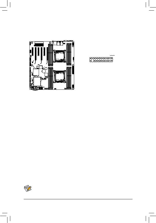
19) BP_1 (HDD Back Plane Board Hearders)
1 2
25 26
|
|
Pin No. |
Definition |
1 |
BP_SGP_CLK |
2 |
NC |
3 |
BP_SGP_GLD |
4 |
FAN_GATE_N |
5 |
BP_SGP_DOUT |
6 |
GND |
7 |
KEY |
8 |
Rreset |
9 |
GND |
10 |
BP_LED_A_N |
11 |
BP_LED_G_N |
12 |
GND |
13 |
BP_SGP_DIN |
14 |
NC |
15 |
GND |
16 |
SMB_BP_DATA |
17 |
GND |
18 |
SMB_BP_CLK |
19 |
P_3V3_AUX |
20 |
BMC_ACK |
21 |
P_3V3_AUX |
22 |
BMC_REQ |
23 |
GND |
24 |
KEY |
25 |
BP_PRESENSE |
26 |
GND |
|
|
- 29 - |
Hardware Installation |
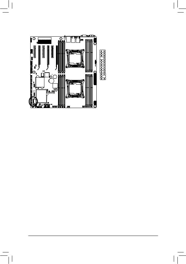
20)F_USB1 (USB 3.0 Header)
The headers conform to USB 3.0 specification. Each USB header can provide two USB ports via an optional USB bracket. For purchasing the optional USB bracket, please contact the local dealer.
|
|
|
Pin No. |
Definition |
|
|
|
|
1 |
Power |
|
20 1 |
|
2 |
IntA_P1_SSRX- |
||
|
3 |
IntA_P1_SSRX+ |
|||
|
|
|
|||
|
|
|
4 |
GND |
|
|
|
|
5 |
IntA_P1_SSTX- |
|
|
|
|
|||
|
|
|
6 |
IntA_P1_SSTX+ |
|
|
|
|
7 |
GND |
|
|
|
|
|||
11 |
10 |
||||
8 |
IntA_P1_D- |
||||
|
|
|
|||
|
|
|
9 |
IntA_P1_D+ |
|
|
|
|
10 |
NC |
|
|
|
|
11 |
IntA_P2_D+ |
|
|
|
|
12 |
IntA_P2_D- |
|
|
|
|
13 |
GND |
|
|
|
|
14 |
IntA_P2_SSTX+ |
|
|
|
|
15 |
IntA_P2_SSTX- |
|
|
|
|
16 |
GND |
|
|
|
|
17 |
IntA_P2_SSRX+ |
|
|
|
|
18 |
IntA_P2_SSRX- |
|
|
|
|
19 |
Power |
|
|
|
|
20 |
No Pin |
|
|
|
|
|
|
|
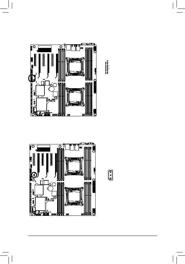
21) IPMB (IPMB Connector)
3 |
|
|
|
Pin No. |
Definition |
|
1 |
Clock |
|
2 |
GND |
1 |
3 |
Data |
Hardware Installation |
- 30 - |
Loading...