


GA-K8VT800(Pro)
AMD Socket 754 Processor Motherboard
User's Manual
Rev. 1005
12ME-K8VT800P-1005
Copyright
© 2005 GIGABYTE TECHNOLOGY CO., LTD
Copyright by GIGA-BYTE TECHNOLOGY CO., LTD. ("GBT"). No part of this manual may be reproduced or transmitted in any from
without the expressed, written permission of GBT.
Trademarks
Third-party brands and names are the property of their respective owners.
Notice
Please do not remove any labels on motherboard, this may void the warranty of this motherboard.
Due to rapid change in technology, some of the specifications might be out of date before publication of this booklet.
The author assumes no responsibility for any errors or omissions that may appear in this document nor does the author make a
commitment to update the information ontained herein.

Mother Board
GA-K8VT800 / GA-K8VT800 Pro
September 2, 2003

Motherboard
GA-K8VT800 / GA-K8VT800 Pro
September 2 ,2003

English
When you installing AGP card, please make sure the following notice is fully understood and
practiced. If your AGP card has "AGP 4X/8X(1.5V) notch" (show below), please make sure your
AGP card is AGP 4X/8X(1.5V).
AGP 2X(3.3V) card is not supported by VIA K8T800 chipset. You might experience system unable
to boot up normally. Please insert an AGP 4X/8X(1.5V) card.
Read Me First !
AGP 4X/8X notch
- 4 -GA-K8VT800(Pro) Motherboard

Preparing Your Computer
Computer motherboards and expansion cards contain very delicate Integrated Circuit (IC) chips. To
protect them against damage from static electricity, you should follow some precautions whenever
you work on your computer.
1. Unplug your computer when working on the inside.
2. Use a grounded wrist strap before handling computer components. If you do not have
one, touch both of your hands to a safely grounded object or to a metal object, such as
the power supply case.
3. Hold components by the edges and try not touch the IC chips, leads or connectors, or
other components.
4. Place components on a grounded antistatic pad or on the bag that came with the
components whenever the components are separated from the system.
5. Ensure that the ATX power supply is switched off before you plug in or remove the ATX
power connector on the motherboard.
Installing the motherboard to the chassis…
If the motherboard has mounting holes, but they don't line up with the holes on the base and there
are no slots to attach the spacers, do not become alarmed you can still attach the spacers to the
mounting holes. Just cut the bottom portion of the spacers (the spacer may be a little hard to cut off,
so be careful of your hands). In this way you can still attach the motherboard to the base without
worrying about short circuits. Sometimes you may need to use the plastic springs to isolate the
screw from the motherboard PCB surface, because the circuit wire may be near by the hole. Be
careful, don't let the screw contact any printed circuit write or parts on the PCB that are near the
fixing hole, otherwise it may damage the board or cause board malfunctioning.
English
The manufacturer assumes no liability for any damage, caused directly or indirectly, by improper
installation of any comfortable performing the installation, consult a qualified computer technician.
Damage to system components, and injury to yourself may result if power is applied during
installation.
5 Read Me First

Table of Content
English
Read Me First ! ....................................................................................... 4
Chapter 1 Introduction ............................................................................ 8
Chapter 2 Hardware Installation Process ............................................. 15
Chapter 3 BIOS Setup ......................................................................... 39
1-1 Item Check List ............................................................................ 8
1-2 Features Summary ................................................................................ 8
1-3 GA-K8VT800(Pro) Motherboard Layout ............................................. 11
1-4 Block Diagram - GA-K8VT800(Pro).................................................... 12
Step 1: Installing Processor and CPU Cooling Fan.................................. 16
Step 2: Installing Memory Modules ........................................................... 18
Step 3: Installing expansion cards ............................................................ 20
Step 3-1: AGP Card Installation..................................................................................... 20
Step 4: Connect ribbon cables, cabinet wires and power supply ............ 21
Step 4-1: I/O Back Panel Introduction........................................................................... 21
Step 4-2: Connectors Introduction ................................................................................. 23
The Main Menu (For example: BIOS Ver. : F1a) ...................................... 40
Standard CMOS Features......................................................................... 42
Advanced BIOS Features .......................................................................... 45
Integrated Peripherals .............................................................................. 47
Power Management Setup ....................................................................... 52
PnP/PCI Configurations ............................................................................. 55
PC Health Status........................................................................................ 56
- 6 -GA-K8VT800(Pro) Motherboard

Frequency/Voltage Control ........................................................................ 58
Load Fail-Safe Defaults ............................................................................. 60
Load Optimized Defaults ........................................................................... 61
Set Supervisor/User Password .................................................................. 62
Save & Exit Setup ....................................................................................... 63
Exit Without Saving ................................................................................... 64
Chapter 4 Technical Reference ........................................................... 67
@BIOS™ Introduction................................................................................. 67
™
EasyTune
Flash BIOS Method Introduction ............................................................... 69
2- / 4- / 6-Channel Audio Function Introduction ........................................ 79
Jack-Sensing Introduction......................................................................... 85
UAJ Introduction ........................................................................................ 87
Xpress Recovery Introduction ................................................................... 89
4 Introduction ......................................................................... 68
English
Chapter 5 Appendix............................................................................. 97
- 7 -
Table of Content

Chapter 1 Introduction
English
1-1 Item Checklist
1-2 Features Summary
Form Factor 30.5cm x 23.0cm ATX size form factor, 4 layers PCB
CPU Socket 754 for AMD AlthlonTM 64 processor (K8)
Chipset VIA K8T800 AGP/PCI Controller (PAC)
Memory 3 184-pin DDR DIMM sockets
I/O Control ITE8705
Slots 1 AGP slot supports 8X/4X mode,
(1)
The GA-K8VT800(Pro) motherboard
CD for motherboard driver & utility
The GA-K8VT800(Pro) user's manual
Quick PC Installation Guide
GigaRAID manual
(1)
GC-SATA Card (optional)
(Manual; SATA cable x 1; Power cable x 1)
IDE cable x 3 / Floppy cable x 1
IDE cable x 1 / Floppy cable x 1
(1)
(2)
128K L1& 256K / 512K / 1M L2 cache on die
800MHz FSB
Support core frequencies in excess of 1.6 GHz(2800+) and faster
VIA VT8237 Integrated Peripheral Controller (PSIPC)
Supports DDR400/DDR333/DDR266 DIMM
Supports unbuffered DIMMs with a 64-bit data bus with optional 8
bits of Error Correcting Code (ECC)
Supports 128MB/256MB/512MB/1GB DRAM
Supports up to 3GB DRAM (Max)
AGP3.0 8X interface at 533MHz
5 PCI slots support 33MHz & PCI 2.3 compliant
For GA-K8VT800 Pro only
(2)
For GA-K8VT800 only
Serial ATA cable x 2
USB & IEEE 1394 Cable x 1
USB Cable x 1
SPDIF Out Kit x 1
(2)
(1)
I/O Shield
Motherboard Settings Label
to be continued......
(1)
- 8 -GA-K8VT800(Pro) Motherboard

On-Board IDE 2 IDE controllers provides IDE HDD/CD-ROM (IDE1, IDE2) with
PIO, Bus Master (Ultra DMA33/ATA66/ATA100/ATA133) operation
modes
IDE3 and IDE4 compatible with RAID, Ultra ATA133/100, IDE
Hardware Monitor CPU/System fan revolution detect
CPU/System temperature detect
CPU warning temperature
System voltage detect
CPU/System fan fail warning
CPU Smart Fan control
(1)
Thermal shutdown function
On-Board Peripherals 1 Floppy port supports 2 FDD with 360K, 720K,1.2M, 1.44M
and 2.88M bytes
1 Parallel port supports Normal/EPP/ECP mode
2 Serial ports (COMA & COMB)
8 USB 2.0/1.1 ports (4 x Front by cable)
3 IEEE1394 ports (by cable)
(1)
1 IrDA connector for IR
1 Front Audio connector
On-Board LAN RTL Gigabit LAN (RTL8110S)
RTL 10/100 LAN (RTL8100C)
(1)
(2)
1 RJ45 ports
On-Board Sound Realtek ALC658 CODEC (UAJ)
Supports Jack Sensing function
Line Out / 2 front speaker
Line In / 2 rear speaker (by s/w switch)
Mic In / center & subwoofer (by s/w switch)
SPDIF In / Out
CD In / AUX In / Game port
On-Board SATA RAID '*' Built-in VT8237
Supports Disk striping (RAID0) or DISK Mirroring (RAID1)
Supports UDMA up to 150 MB/sec.
Up to 2 SATA devices
(Note)
English
to be continued......
'*' If you want to find the detailed information for SATA RAID setup installation,
please download the VT8237 SATA Manual from GIGABYTE’s website.
(Note) It is recommended to use SATA (1.5Gb/s) hard disks.
(1)
For GA-K8VT800 Pro only
(2)
For GA-K8VT800 only
- 9 -
Introduction

On-Board IDE RAID
English
On-Board IEEE1394
PS/2 Connector PS/2 Keyboard interface and PS/2 Mouse interface
BIOS Licensed AWARD BIOS
Additional Features PS/2 Keyboard power on by password
Overclocking Over Voltage (CPU/DDR/AGP) by BIOS
(1)
Onboard GigaRAID IT8212F chipset
Supports data striping (RAID 0) or mirroring (RAID 1) or
striping+mirroring (RAID 0 + RAID 1)
Supports JBOD function
Supports concurrent dual ATA133 IDE controller operation
Support ATAPI mode for HDD
Supports IDE bus master operation
Support ATA133/RAID mode switch by BIOS
Displays status and error checking messages during boot-up
Mirroring supports automatic background rebuilds
Features LBA and Extended Interrupt 13 drive translation in
controller onboard BIOS
(1)
Built-in Ti TSB43AB23
Supports Dual BIOS
Supports Face Wizard
(1)
(1)
Supports Q-Flash
PS/2 Mouse power on
External Modem wake up
STR(Suspend-To-RAM)
Wake on LAN (WOL)
AC Recovery
Poly fuse for keyboard over-current protection
USB KB/Mouse wake up from S3
Supports Thermal Shutdown function
Supports Easy Tune4
Supports @BIOS
Over Clock (CPU/DDR/AGP) by BIOS
Please set the CPU host frequency in accordance with your processor's specifications.
We don't recommend you to set the system bus frequency over the CPU's specification because
these specific bus frequencies are not the standard specifications for CPU, chipset and most of the
peripherals. Whether your system can run under these specific bus frequencies properly will
depend on your hardware configurations, including CPU, Chipsets, SDRAM, Cards…etc.
(1)
For GA-K8VT800 Pro only
- 10 -GA-K8VT800(Pro) Motherboard

1-3 GA-K8VT800(Pro) Motherboard Layout
English
KB_MS
COMB
COMA
AUDIO
CODEC
AUX_IN
USB
USB
LPT
LAN
ITE8705
BACKUP
BIOS
GAME
F_AUDIO
CD_IN
(1)
MAIN
BIOS
NB_FAN
(2)
(1)
RTL8100C
SUR_CEN
ATX_12V
(1)
RTL8110S
SPDIF_IO
IR
CPU_FAN
SOCKET 754
F2_1394
VIA K8T800
PCI1
PCI2
PCI3
PCI4
PCI5
(1)
F1_1394
GA-K8VT800(Pro)
AGP
(1)
TSB43AB23
IDE4
IDE3
F_USB1
(1)
DDR1
VIA VT8237
GigaRAID
IT8212
(1)
(1)
F_USB2
DDR2
(1)
DDR3
RAM_LED
ATX
IDE2
SATA1
SATA0
BAT
PWR_LED
F_PANEL
FDD
IDE1
PWR_FAN
SYS_FAN
CLR_PWD
INFO_LINK
(1)
(1)
For GA-K8VT800 Pro only
(2)
For GA-K8VT800 only
- 11 -
Introduction
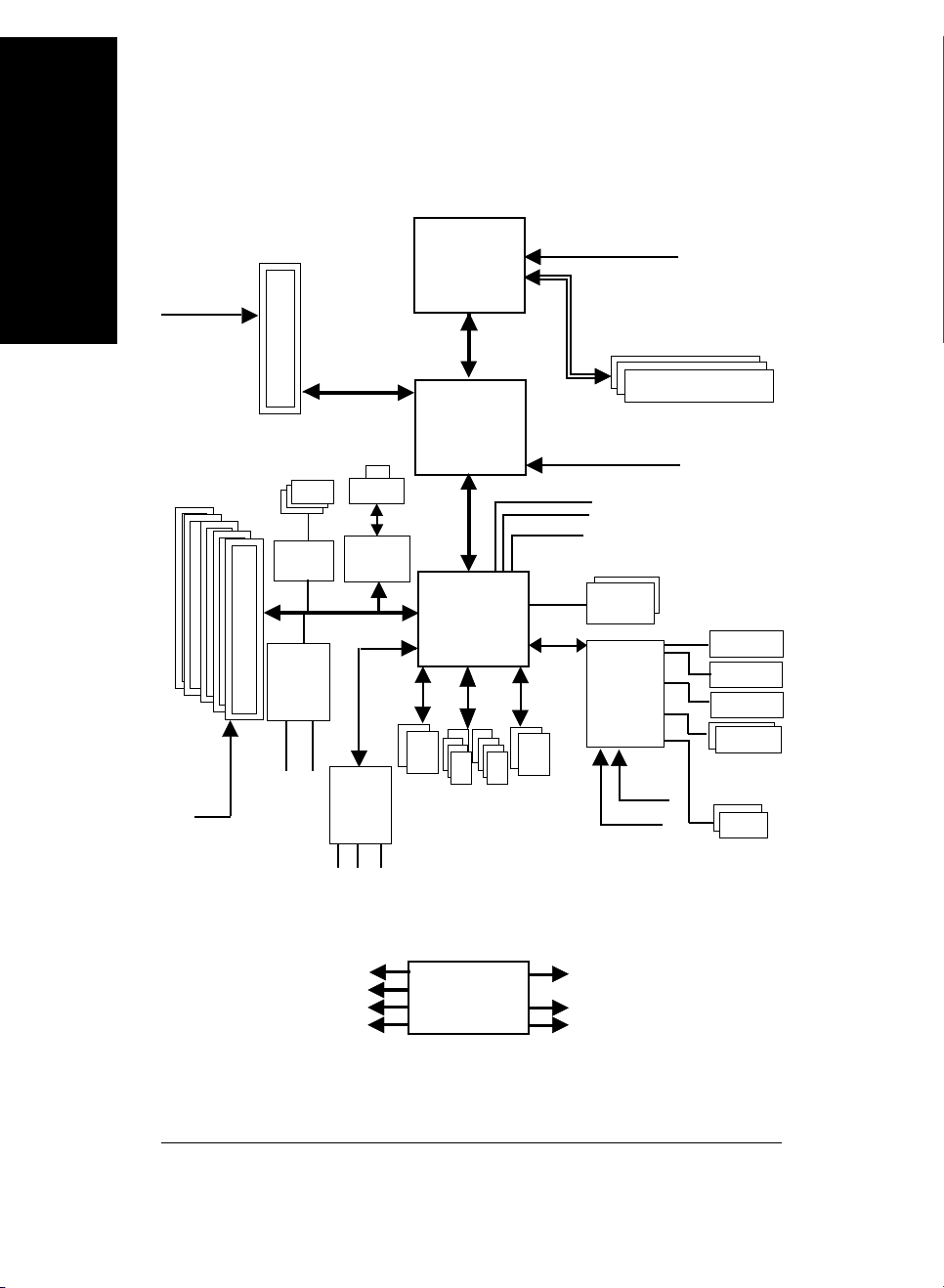
1-4 Block Diagram - GA-K8VT800(Pro)
English
AGPCLK
(66MHz)
5 PCI
PCICLK
(33MHz)
AGP slot
4X/8X
3 IEEE1394
TSB43AB23
GigaRAID
IT8212
IDE4
(1)
(1)
IDE3
(1)
(1)
RTL8110S
(1)
RTL8100C
AC97
CODEC
MIC
LAN
RJ45
AC97 Link
LINE-IN
Althlon
processor (K8)
(1)
(2 )
2 SATA
Ports
LINE-OUT
AMD
TM
64
System Bus
800MHz
VIA
K8T800
66MHz V_Link
VIA
VT8237
ATA66/100/133
8 USB
IDE Channels
Ports
CPUCLK+/- (200MHz)
AGPCLK66MHz
33 MHz
48 MHz
14.318 MHz
PS/2
KB/Mouse
IT8705
33 MHz
DDR400/333/266 DIMM
DDR RAM
Game Port
Floppy
LPT Port
Dual BIOS
24 MHz
COM
Ports
(1)
PCICLK (33MHz)
USBCLK (48MHz)
14.318 MHz
(1)
For GA-K8VT800 Pro only
33 MHz
(2)
For GA-K8VT800 only
CLK
GEN
- 12 -GA-K8VT800(Pro) Motherboard
CPUCLK+/- (200MHz)
AGPCLK (66MHz)
V_Link (66MHz)

English
- 13 -
Introduction

English
- 14 -GA-K8VT800(Pro) Motherboard

Chapter 2 Hardware Installation Process
To set up your computer, you must complete the following steps:
Step 1- Installing Processor and CPU Cooling Fan
Step 2- Installing Memory Modules
Step 3- Installing Expansion Cards
Step 4- Connect ribbon Cables, Cabinet Wires, And Power Supply
English
Step 4
Step 4
Step 3
Congratulations! You have accomplished the hardware installation!
Turn on the power supply or connect the power cable to the power outlet. Continue with the
BIOS/software installation.
Step 1
Step 2
Step 4
- 15 -
Hardware Installation Process
Step 1: Installing Processor and Heatsink
Before installing the processor and heatsink, adhere to the following warning:
English
1.1 The installation of the processor and heatsink is performed in four main steps:
Step 1-1. Processor insertion
Step 1-2. Applying thermal grease
Step 1-3. Heatsink attachment
Step 1-4. Connecting processor fan power
These steps are described in detail in the following paragraphs.
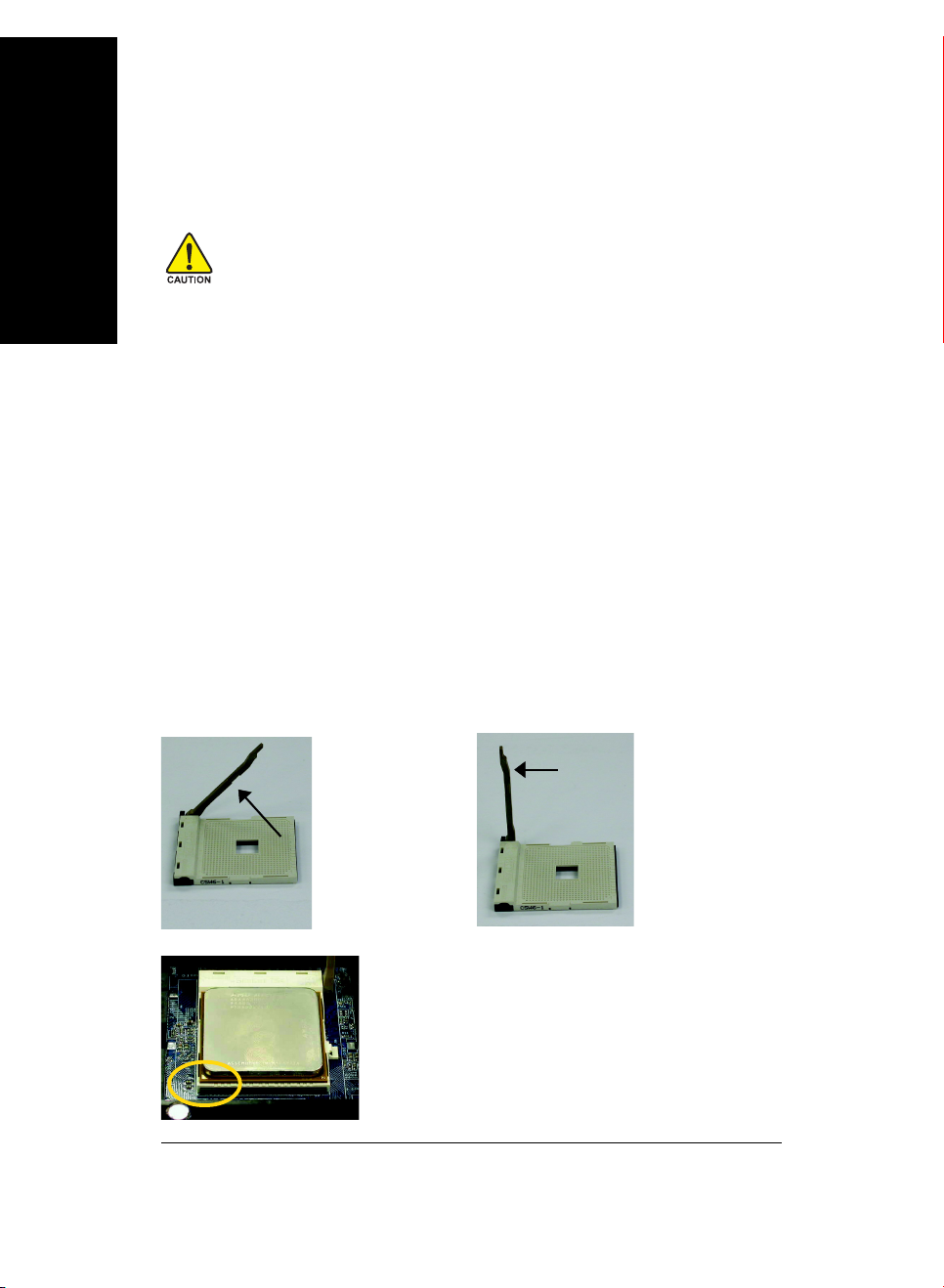
Step 1-1. First, check the processor pins to see that none are bent. Move the socket lever to the
unlocked position as shown in Figure 1 & Figure 2.(90 to the plane of the motherboard) prior to
inserting the processor. The A1 pin location is designated on the processor by a copper triangle that
matches up to a triangle on the socket as shown in Figure 3. Align the processor to the socket and
gently lower it into place. Do not force the processor into the socket.
1. The processor will overheat without the heatsink and/or fan, resulting in permanent
irreparable damage.
2. Never force the processor into the socket.
3. Apply thermal paste between the processor and heatsink.
4. Please make sure the CPU type is supported by the motherboard.
5. If you do not match the CPU socket Pin 1 and CPU cut edge well, it will cause improper
installation. Please change the insert orientation. Please use AMD approved cooling
fan.
Angling the
rod to 65
0
Figure 1.Angling the rod
to 65-degree maybe feel
a kind of tight , and then
continue pull the rod to 90-
degree when a noise
“cough” made.
Socket
Actuation
Lever
Figure 2.Pull the rod to
the 90-degree directly.
Figure 3. A1 pin location on the Socket and
Processor.Move the socket lever to the locked
position while holding pressure on the center of the
processor.
- 16 -GA-K8VT800(Pro) Motherboard
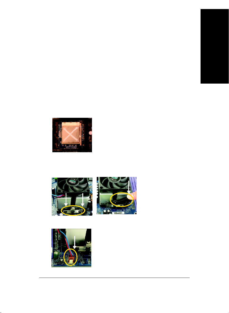
Step1-2. When the processor is installed in the socket, apply thermal grease to the processor(as
shown in Figure 4) prior to installing the heatsink. AMD recommends using a high thermal
conductivity grease (such as Shin-Etsu types G751 or G749, or an equivalent product) for
the thermal interface material rather than a phase change material. Phase change materials
develop strong adhesive forces between the heatsink and processor.
Removing the heatsink under such conditions can cause the processor to be
removed from the socket without moving the socket lever to the unlocked
position and then damage the processor pins or socket contacts.
** We recommend you to apply the thermal tape to provide better heat conduction between your
CPU and heatsink. (The CPU cooling fan might stick to the CPU due to the hardening of the
thermal paste. During this condition if you try to remove the cooling fan, you might pull the
processor out of the CPU socket alone with the cooling fan, and might damage the processor.
To avoid this from happening, we suggest you to either use thermal tape instead of thermal
paste, or remove the cooling fan with extreme caution.)
Figure 4. Application of Thermal Grease to the processor.
Step 1-3.Once the thermal grease has been applied to the processor, the heatsink can be attached to
the processor. Align the heatsink assembly with the support frame mating with the backer
plate standoffs as shown in Figure 5&6.
English
Figure 5&6 Alignment of Heatsink
Assembly with Standoffs
Step 1-4. Connect the fan power wires to the header on the motherboard as shown in Figure 7.
Figure 7. Connecting the Fan Power Wires
- 17 -
Hardware Installation Process

Step 2: Installing Memory Modules
English
The motherboard supports DDR memory modules, whereby BIOS will automatically detect memory
capacity and specifications. Memory modules are designed so that they can be inserted only in one
direction. The memory capacity used can differ with each slot.
Before installing the memory modules, please comply with the following conditions:
1. Please make sure that the memory used is supported by the motherboard. It is
recommended that memory of similar capacity, specifications and brand be used.
2. Before installing or removing memory modules, please make sure that the computer
power is switched off to prevent hardware damage.
3. Memory modules have a foolproof insertion design. A memory module can be installed
in only one direction. If you are unable to insert the module, please switch the direction.
Notch
DDR
Fig.1
The DIMM socket has a notch, so the DIMM memory module can
only fit in one direction. Insert the DIMM memory module vertically
into the DIMM socket. Then push it down.
Fig.2
Close the plastic clip at both edges of the DIMM sockets to lock the
DIMM module.
Reverse the installation steps when you wish to remove the DIMM
module.
- 18 -GA-K8VT800(Pro) Motherboard

DDR Introduction
Established on the existing SDRAM infrastructure, DDR (Double Data Rate) memory is a high
performance and cost-effective solution that allows easy adoption for memory vendors, OEMs, and
system integrators.
DDR memory is a great evolutionary solution for the PC industry that builds on the existing SDRAM
architecture, yet make the awesome advances in solving the system performance bottleneck by doubling
the memory bandwidth. Nowadays, with the highest bandwidth of 3.2GB/s of DDR400 memory and
complete line of DDR400/333/266/200 memory solutions, DDR memory is the best choice for building
high performance and low latency DRAM subsystem that are suitable for servers, workstations, and full
range of desktop PCs.
Please refer to the recommended memory configuration table below before installing memory.
Recommended Memory Configurations (SS: Single -Sided, DS:Double-Sided)
Number of DIMMs
1
1
1
1
1
1
2
2
2
2
2
2
3
3
DDR1 DDR2 DDR3
SS -- -- DDR 400
-- SS -- DDR 400
-- -- SS DDR 400
DS -- -- DDR 400
-- DS -- DDR 400
-- -- DS DDR 400
SS SS -- DDR 400
-- SS SS DDR 400
SS -- SS DDR 400
DS DS -- DDR 400
-- DS DS DDR 333
DS -- DS DDR 400
SS SS SS DDR 400
DS DS DS DDR 333
DIMM Socket Max. Memory Speed
English
- 19 -
Hardware Installation Process

Step 3 Install expansion cards
Step 3-1: AGP Card Installation
English
1. Read the related expansion card's instruction document before install the expansion card into the computer.
2. Remove your computer's chassis cover, screws and slot bracket from the computer.
3. Press the expansion card firmly into expansion slot in motherboard.
4. Be sure the metal contacts on the card are indeed seated in the slot.
5. Replace the screw to secure the slot bracket of the expansion card.
6. Replace your computer's chassis cover.
7. Power on the computer, if necessary, setup BIOS utility of expansion card from BIOS.
8. Install related driver from the operating system.
Please carefully pull out the small white-drawable bar at the end of the AGP slot when you try
to install / uninstall the AGP card. Please align the AGP card to the onboard AGP slot and
press firmly down on the slot. Make sure your AGP card is locked by the small whitedrawable bar.
- 20 -GA-K8VT800(Pro) Motherboard

Step 4: Connect ribbon Cables, Cabinet Wires And Power Supply
Step 4-1: I/O Back Panel Introduction
English
PS/2 Keyboard and PS/2 Mouse Connector
PS/2 Mouse Connector
(6 pin Female)
PS/2 Keyboard Connector
(6 pin Female)
/ USB/LAN Connector
LAN
USB 0
USB 1
USB 2
USB 3
This connector supports standard PS/2
keyboard and PS/2 mouse.
Before you connect your device(s) into USB
connector(s), please make sure your device(s)
such as USB keyboard,mouse, scanner, zip,
speaker...etc. Have a standard USB interface.
Also make sure your OS supports USB
controller. If your OS does not support USB
controller, please contact OS vendor for
possible patch or driver upgrade. For more
information please contact your OS or device
(s) vendors.
- 21 -
Hardware Installation Process

Parallel Port, Serial Ports (COMA / COMB)
English
Parallel Port (25-pin Female)
COMA COMB
Serial Port (9-pin Male)
According to your motherboard, please see the
following descriptions for the devices. Device
like printer can be connected to Parallel port;
mouse and modem etc. can be connected to
Serial ports.
Audio Connectors
Line In (Rear Speaker)
Line Out (Front Speaker)
MIC In (Center and Subwoofer)
If you want the detail information for 2-/4-/6-channel audio setup
installation, please refer to page 79.
After install onboard audio driver, you may connect speaker to Line Out jack, microphone to MIC
In jack. Device like CD-ROM,walkman etc. can
be connected to Line-In jack.
Please note:
You are able to use 2-/4-/6-channel audio feature
by S/W selection.
If you want to enable 6-channel function, you
have 2 choose for hardware connection.
Method1:
Connect "Front Speaker" to "Line Out"
Connect "Rear Speaker" to "Line In"
Connect "Center and Subwoofer" to "MIC Out ".
Method2:
You can refer to page 32, and contact your
nearest dealer for optional SUR_CEN cable.
- 22 -GA-K8VT800(Pro) Motherboard

Step 4-2: Connectors Introduction
1
English
3
2
14
7
6
15
19
18
23
16
1) ATX_12V
2) ATX (Power Connector)
3) CPU_FAN
4) SYS_FAN
5) PWR_FAN
6) NB_FAN
(1)
(1)
7) FDD
8) IDE1 / IDE2
9) IDE3 / IDE4
(1)
10) SATA0 / SATA1
11) F_PANEL
12) BAT
13) PWR_LED
17
22 21
12
20
11
14) RAM_LED
15) F_AUDIO
16) SUR_CEN
17) SPDIF_IO
18) CD_IN
19) AUX_IN
20) F_USB1 / F_USB2
21) F1_1394 / F2_1394
22) IR
23) GAME
24) INFO_LINK
25) CLR_PWD
8
5
10
4
25
24
9
13
(1)
(1)
For GA-K8VT800 Pro only
- 23 -
Hardware Installation Process

1) ATX_12V (+12V Power Connector)
_
English
2) ATX (ATX Power)
This connector (ATX_12V) supplies the CPU operation voltage (Vcore).
If this "ATX_12V connector" is not connected, system cannot boot.
Pin No. Definition
12
4
3
1 GND
2 GND
3 +12V
4 +12V
AC power cord should only be connected to your power supply unit after ATX power cable and
other related devices are firmly connected to the mainboard.
11
20
1
10
Pin No. Definition
1 3.3V
2 3.3V
3 GND
4 VCC
5 GND
6 VCC
7 GND
8 Power Good
9 5V SB (stand by +5V)
10 +12V
11 3.3V
12 -12V
13 GND
14 PS_ON(soft on/off)
15 GND
16 GND
17 GND
18 -5V
19 VCC
20 VCC
- 24 -GA-K8VT800(Pro) Motherboard
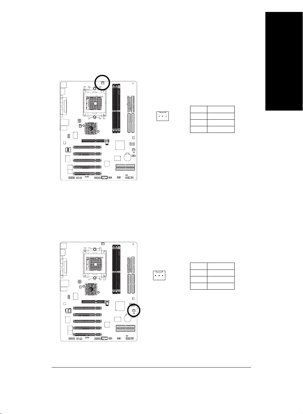
3) CPU_FAN (CPU Fan Connector)
Please note, a proper installation of the CPU cooler is essential to prevent the CPU from running
under abnormal condition or damaged by overheating. The CPU fan connector supports Max.
current up to 600 mA.
Pin No. Definition
1
1 GND
2 +12V
3 Sense
4) SYS_FAN (System Fan Connector)
This connector allows you to link with the cooling fan on the system case to lower the system
temperature.
English
- 25 -
Pin No. Definition
1
1 GND
2 +12V
3 Sense
Hardware Installation Process

5) PWR_FAN (Power Fan Connector)
English
11
(
1)
11
This connector allows you to link with the cooling fan on the system case to lower the system
temperature.
6) NB_FAN (Chip Fan Connector)
1
11
(
1)
11
Pin No. Definition
1 GND
2 +12V
3 Sense
If you installed wrong direction, the chip fan will not work. Sometimes will damage the chip fan.
(Usually black cable is GND)
Pin No. Definition
1
1 VCC
2 GND
(1)
For GA-K8VT800 Pro only
- 26 -GA-K8VT800(Pro) Motherboard

7) FDD (Floppy Connector)
Please connect the floppy drive ribbon cables to FDD. It supports 360K, 1.2M, 720K, 1.44M and
2.88M bytes floppy disk types.
The red stripe of the ribbon cable must be the same side with the Pin1.
English
34
2
8) IDE1 / IDE2 (IDE1 / IDE2 Connector)
Important Notice:
Please connect first hard disk to IDE1 and connect CD-ROM to IDE2.
The red stripe of the ribbon cable must be the same side with the Pin1.
33
1
3940
- 27 -
IDE2
12
IDE1
Hardware Installation Process
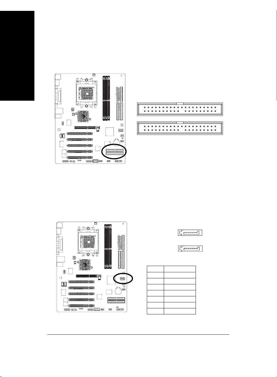
9) IDE3 / IDE4 (RAID/ATA133, Green Connector)
English
10) SATA0 / SATA1 (Serial ATA Connector)
11
(
1)
11
Important Notice: The red stripe of the ribbon cable must be the same side with the Pin1. If you wish
to use IDE3 and IDE4, please use it in unity with BIOS (either RAID or ATA133). Then, install the
correct driver to have proper operation. For details, please refer to the GigaRAID manual.
139
IDE4
IDE3
240
You can connect the Serial ATA device to this connector, it provides you high speed transfer rates
(150MB/sec).If you wish to use SATA0 and SATA1, please Enable " OnChip Serial ATA " item.
Then, install the correct driver to have proper operation. For details, please refer to the VT8237
SATA Manual at GIGABYTE's website.
(1)
For GA-K8VT800 Pro only
- 28 -GA-K8VT800(Pro) Motherboard
1
Pin No. Definition
1 GND
2TXP
3 TXN
4 GND
5 RXN
6 RXP
7 GND
7
SATA1
71
SATA0

11) F_PANEL (2 x 10 pins Connector)
Please connect the power LED, PC speaker, reset switch and power switch etc. of your chassis
front panel to the F_PANEL connector according to the pin assignment above.
English
Message LED/
Power/
Sleep LED
11
2
1
1
IDE Hard Disk Active LED
Soft Power
Connector
MSG+
MSG-
HD-
HD+
Reset Switch
PW+
RES-
1
RES+
PW-
NC
Speaker Connector
SPEAK+
SPEAK-
1
20
19
HD (IDE Hard Disk Active LED) Pin 1: LED anode(+)
(Blue) Pin 2: LED cathode(-)
SPK (Speaker Connector) Pin 1: VCC(+)
(Amber) Pin 2- Pin 3: NC
Pin 4: Data(-)
RES (Reset Switch) Open: Normal Operation
(Green) Close: Reset Hardware System
PW (Soft Power Connector) Open: Normal Operation
(Red) Close: Power On/Off
MSG(Message LED/ Power/ Sleep LED) Pin 1: LED anode(+)
(Yellow) Pin 2: LED cathode(-)
NC (Purple) N C
- 29 -
Hardware Installation Process

12) BATTERY
English
13) PWR_LED
+
CAUTION
Danger of explosion if battery is incorrectly
replaced.
Replace only with the same or equivalent type
recommended by the manufacturer.
Dispose of used batteries according to the
manufacturer's instructions.
If you want to erase CMOS...
1. Turn OFF the computer and unplug the power
cord.
2. Take out the battery gently and put it aside for
about 10 minutes. (Or you can use a metal
object to connect the positive and negative pins
in the battery holder to makethem short for one
minute.)
3. Re-install the battery.
4. Plug the power cord and turn ON the computer.
PWR_LED is connect with the system power indicator to indicate whether the system is on/off.
It will blink when the system enters suspend mode. If you use dual color LED, power LED will turn
to another color.
1
- 30 -GA-K8VT800(Pro) Motherboard
Pin No. Definition
1 MPD+
2 MPD-
3 MPD-
 Loading...