

Page 1

GA-K8VM800M
AMD Socket 754 Processor Motherboard
User's Manual
Rev. 1001
12ME-K8VM800M-1001
Copy ri ght
© 2004 GIGABYTE TECHNOLOGY CO., LTD
Copyright by GIGA-BYTE TECHNOLOGY CO., LTD. ("GBT"). No part of this manual may be reproduced or transmitted in any from
without the expressed, written permission of GBT.
Tra demar ks
Third-party brands and names are the property of their respective owners.
Not ice
Please do not remove any labels on motherboard, this may void the warranty of this motherboard.
Due to rapid change in technology, some of the specifications might be out of date before publication of this booklet.
The author assumes no responsibility for any errors or omissions that may appear in this docum ent nor does the author make a
com mitment to update the information contained herein.
Page 2
Mother Board
GA-K8VM800M
Apr. 14, 2 004
Page 3
Motherboard
GA-K8VM800M
Apr. 14, 2004
Page 4
English
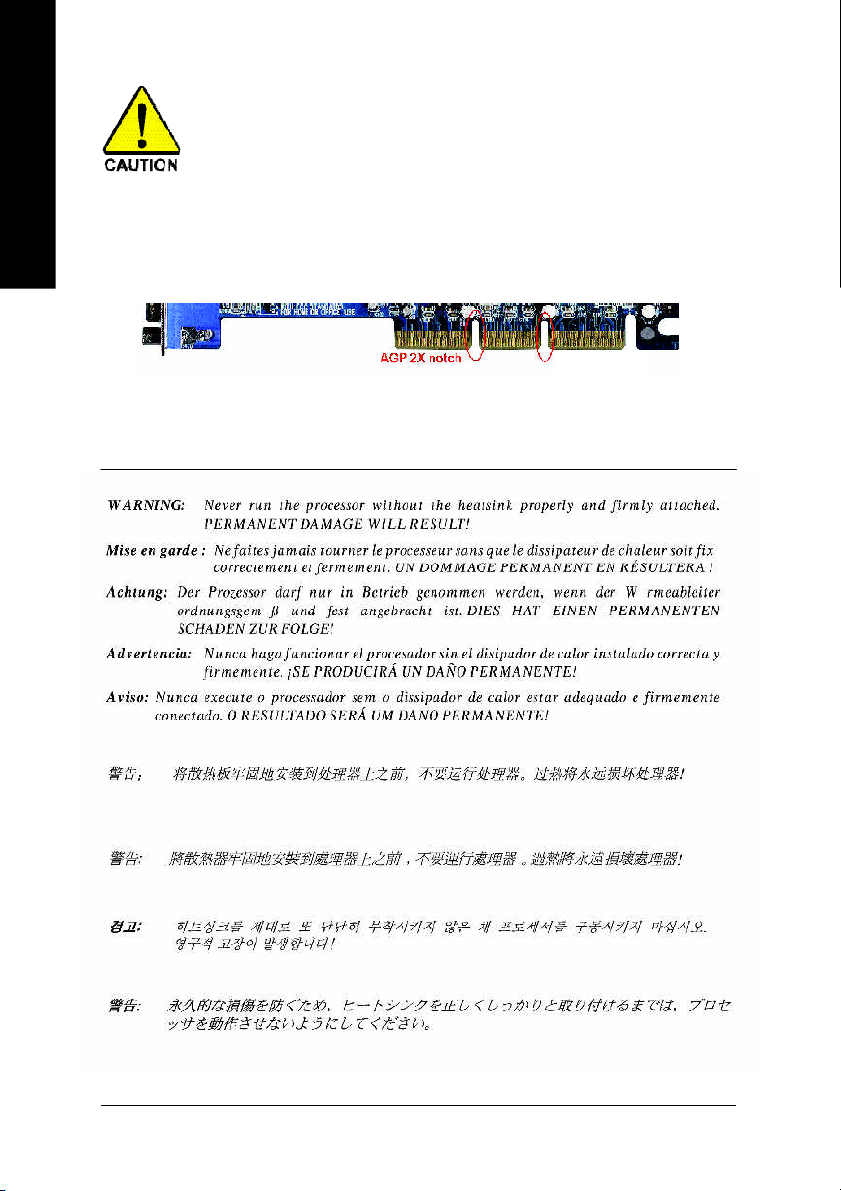
When you installing AGP card, please make sure the following notice is fully understood and
practiced. If your AGP card has "AGP 4X/8X (1.5V) notch" (show below), please make sure
your AGP card is AGP 4X/8X.
Caution: AGP 2X card is not supported by VIA K8M800. You might experience
system unable to boot up normally. Please insert an AGP 4X/8X card.
Read Me First!
AGP 4X/8X notch
GA-K8VM 800M Motherboard
- 4 -
Page 5

Prepare your computer...
Computer motherboards and expansion cards contain very delicate Integrated Circuit (IC) chips. To
protect them against damage from static electricity, you should follow some precautions whenever you
work on your computer.
1. Unplug your computer when working on the inside.
2. Use a grounded wrist strap before handling computer components. If you do not have one,
touch both of your hands to a safely grounded object or to a metal object, such as the power
supply case.
3. Hold components by the edges and try not touch the IC chips, leads or connectors, or other
components.
4. Place components on a grounded antistatic pad or on the bag that came with the components
whenever the components are separated from the system.
5. Ensure that the ATX power supply is switched off before you plug in or remove the ATX power
connector on the motherboard.
Installing the motherboard to the chassis...
If the motherboard has mounting holes, but they don't line up with the holes on the base and there
are no slots to attach the spacers, do not become alarmed you can still attach the spacers to the
mounting holes. Just cut the bottom portion of the spacers (the spacer may be a little hard to cut off, so
be careful of your hands). In this way you can still attach the motherboard to the base without worrying
about short circuits. Sometimes you may need to use the plastic springs to isolate the screw from the
motherboard PCB surface, because the circuit wire may be near by the hole. Be careful, don't let the
screw contact any printed circuit write or parts on the PCB that are near the fixing hole, otherwise it
may damage the board or cause board malfunctioning.
English
- 5 -
Read M e Fi rst!
Page 6

Table of Content
English
Read Me First! ....................................................................................4
Chapter 1 Introduction ........................................................................ 8
Chapter 2 Hardware Installation Process ........................................... 13
Chapter 3 BIOS Setup .......................................................................35
Features Summary ......................................................................................... 8
GA-K8VM800M Motherboard Layout .......................................................... 11
Block Diagram .............................................................................................. 12
Step 1: Install the Central Processing Unit (CPU) ...................................... 14
Step 2: Install Memory Modules .................................................................. 16
Step 3: Install expansion cards .................................................................... 17
Step 4: Connect ribbon cables, cabinet wires and power supply............. 18
Step 4-1: I/O Back Panel Introduction ....................................................................... 18
Step 4-2: Connectors Introduction .............................................................................20
The Main Menu (For example: BIOS Ver. : D8) ......................................... 36
Standard CM OS Features ........................................................................... 3 8
Advanced BIOS Features ............................................................................. 40
Integrated Peripherals ................................................................................. 41
Power Management Setup .......................................................................... 44
PnP/PCI Configurations ................................................................................ 45
PC Health Status ........................................................................................... 4 6
Frequency/Voltage Control ........................................................................... 4 7
Load Fail-Safe Defaults ................................................................................ 48
Load Optimized Defaults .............................................................................. 48
GA-K8VM 800M Motherboard
- 6 -
Page 7

Set Supervisor/User Password..................................................................... 49
Save & Exit Setup .......................................................................................... 5 0
Exit Without Saving ....................................................................................... 50
Chapter 4 Technical Reference ......................................................... 53
@BIOS™ Introduction .................................................................................. 5 3
Flash BIOS Method Introduction ................................................................. 54
2-/4-/6-Channel Audio Function Introduction ............................................. 5 8
Jack-Sensing Introduction ........................................................................... 6 4
Xpress Recovery Introduction ...................................................................... 66
Serial ATA RAID BIOS Utility Introduction .................................................... 7 1
Chapter 5 Appendix ......................................................................... 79
English
- 7 -
Table of Content
Page 8

Chapter 1 Introduction
English
Features Summary
CP U — Socket 754 for AMD AlthlonTM 64 p rocessor (K8)
Chipset — Northbridge:VIA K8M800
Mem ory — 2 184-pin DDR DIMM sockets,supports up to 2GB DRAM (M ax)
Slots — 1 AGP slot supports 8X/4X(1.5V) mode
On-Board IDE — 2 IDE bus master (UDM A33/ATA66/ATA100/ATA133) IDE ports
On-Board Fl oppy — 1 Floppy po rt supports 2 FDD
On-Board Serial ATA — 2 S erial ATA connectors
On-Board Peripherals — 1 Parallel port
On-Board VGA — Build in VIA K 8M800 Ch ipset
On-Board LAN — Built-in RTL8100C (10/100 M bit)
On-Board Sound — ALC655 CODEC
On-Board SATA RAID — Built-in VIA VT8237
I/O Control — IT8705F
128K L1& 256 K / 512 K / 1M L2 cache on die , 800MHz FSB
— Support core frequencies in excess of 1.6 GHz(2800+) and faster
— Southbridge:VIA VT8237
— Supports DDR400/333/266/200 DIMM
— Supports 128MB/256MB/51 2MB/1GB unbuffered DRAM
— Supports only 2.5V DDR DIMM
— 3 PCI slots
for up to 4 ATAPI devic es
— 1 Serial port (COM A),1 VGA p ort,COMB on board
— 8 USB 2.0/1.1 por ts (4 x Rear, 4 xFr ont by cable)
— 1 Front Audio con nector
— 1 IrDA connector for IR
— 1 PS/2 keybo ard
— 1 PS/2 m ouse
— 1 RJ45 port
— Supports Jack Sensing function
— Support 2 / 4 / 6 channel
— Line In / Line Out / M ic In
— SPDIF In / Out
— CD In / Gam e connector
— Supports disk striping ( RAID 0) or disk m irroring (RA ID 1)
— Supports UDM A up to 150 M B/sec
— Up to 2 SATA devic es
GA-K8VM 800M Motherboard
to be continued...
- 8 -
Page 9

Hardware Monitor — CPU/Sy stem fan revo lution detect
— CPU temperature detect
— System voltage detect
— CPU/S ystem fan fail warni ng
BIOS — Licensed A WARD B IOS
— Supports Q-Flash
Additional Features — Supports Therm al Shutdown function
— Supports @BIOS
— Supports Ea syTune
Overc locki ng — Over Clock (C PU/DD R/AGP /PCI) by BIOS
Form F actor — Mic ro ATX size form factor 24.4cm x 24.4cm
English
- 9 -
Introduction
Page 10
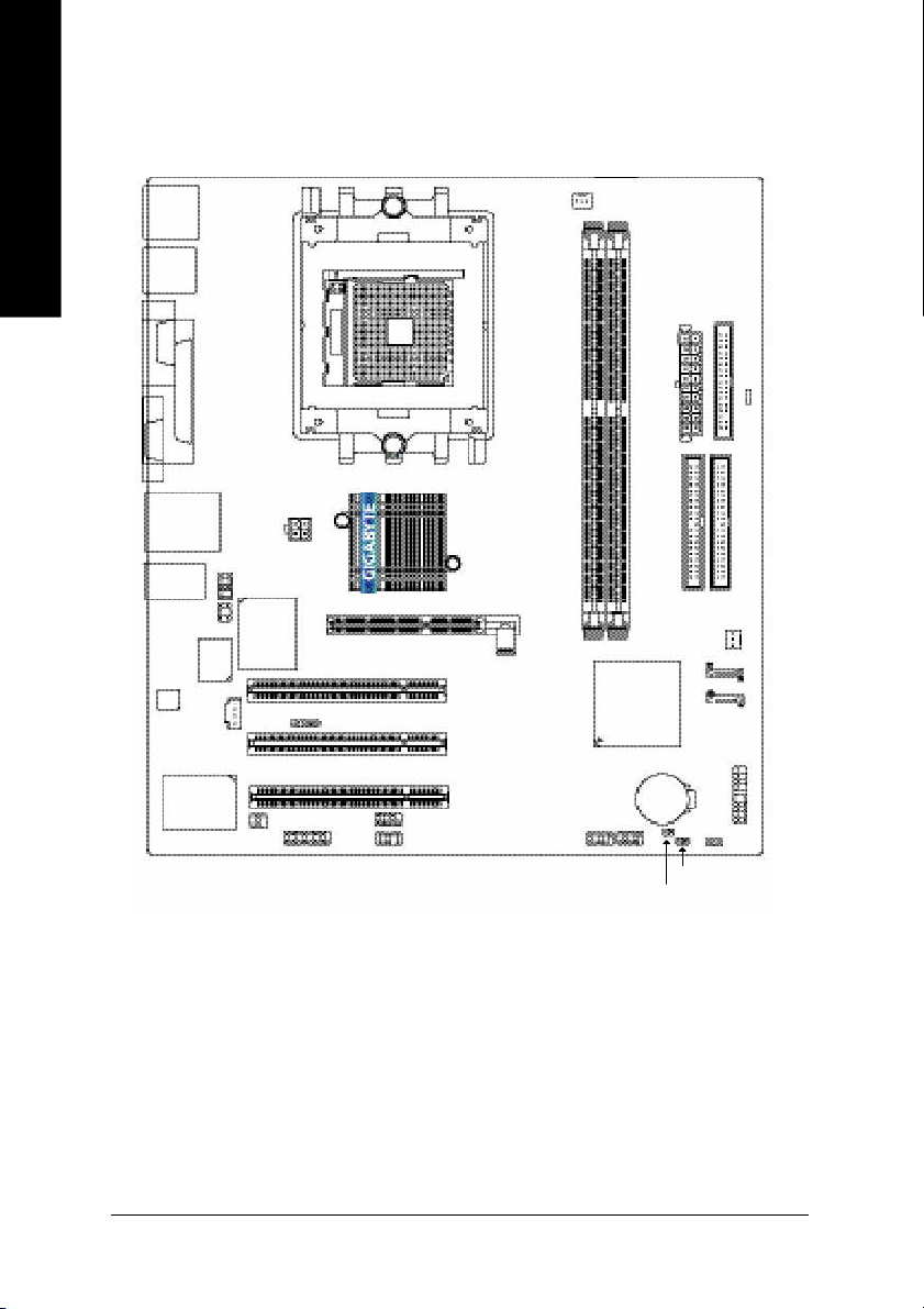
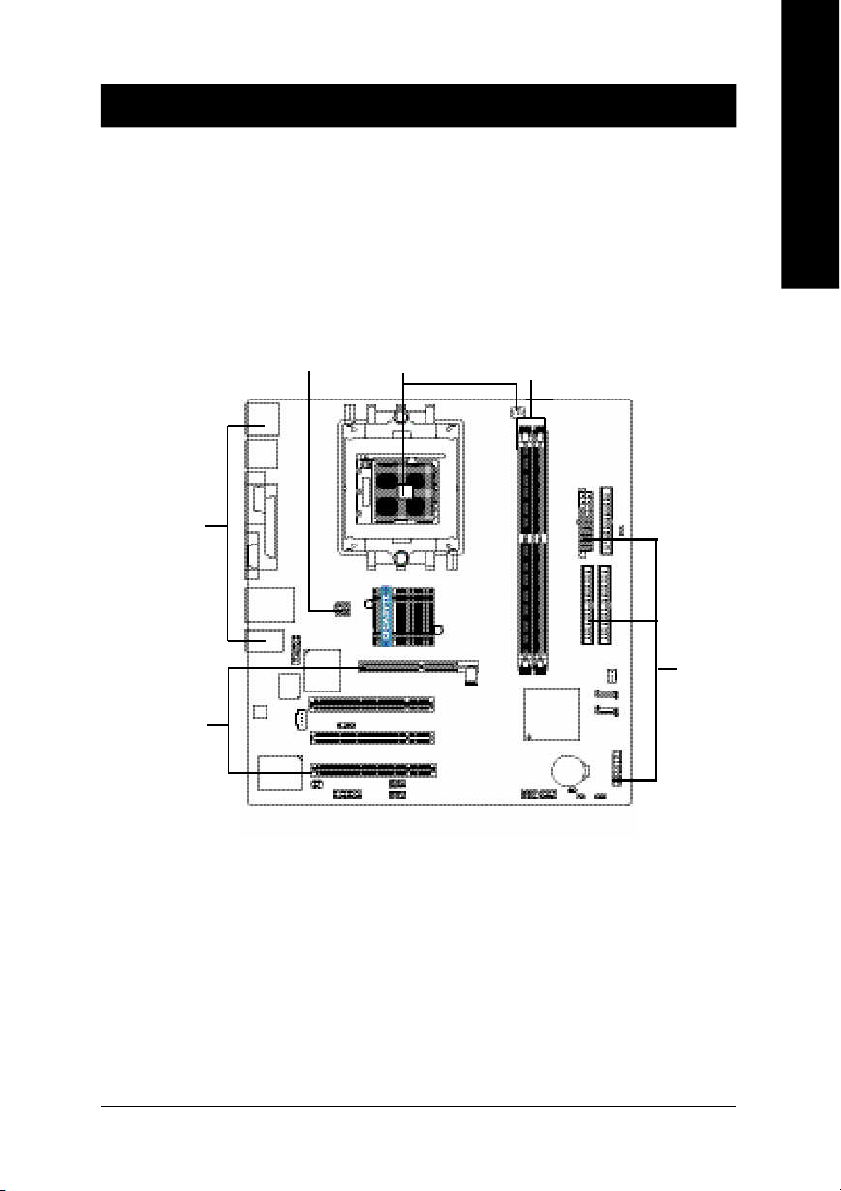
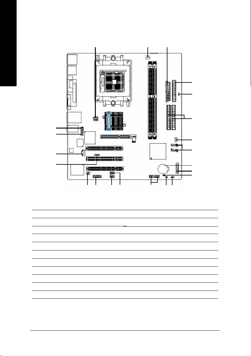
GA-K8VM800M Motherboard Layout
English
MS / KB
R_USB
COMA
VGA
USB
AUDIO
SU R_CEN
CODEC
RTL 8 10 0C
LPT
LAN
BIOS
F_AU DIO
CD _IN
SPDIF_IO
ATX_12 V
IT8705F
GAME
AGP
IR
SOC KET 754
VIA K8M 800
PCI1
PCI2
PCI3
COMB
INFO_LINK
CPU_FAN
GA-K8VM800M
DDR1
VIA
VT8 2 37
F_U SB2F_U SB1
DDR2
BATTERY
CI
ATX
IDE2
SYS_FAN
PWR_ LED
CLR_CMOS
FDD
RAM_LED
IDE1
SATA1
SATA0
F_PANEL
GA-K8VM 800M Motherboard
- 10 -
Page 11
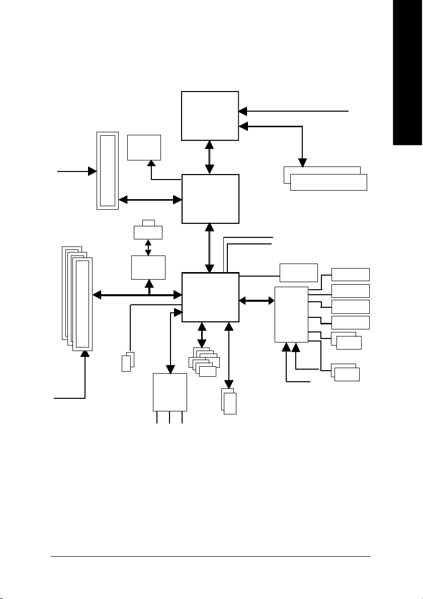
Block Diagram
English
AGPC LK
(66MHz)
3 P CI
PCICL K
(33MHz)
AGP
4X/8X
2 Serial ATA
VGA Port
LAN
RJ45
RTL8100C
Audio
CODE C
MIC
LINE-IN
AMD
AlthlonTM 64
processor (K8)
VIA K8M800
VIA VT8237
AC97 Link
8 U SB
Ports
LINE-OUT
CPUCLK+/- (200M Hz)
H.T. Bus 800M Hz
LPC BUS
ATA33/66/100/133
IDE Channels
DDR RAM
400/333/266/200MHz
33 MHz
14.318 MHz
BIOS
IT8705F
24 M Hz
33 M Hz
IR
Game Port
Flop py
LPT Port
PS/2 KB /Mou se
2 COM Ports
- 11 -
Introduction
Page 12

English
GA-K8VM 800M Motherboard
- 12 -
Page 13
Chapter 2 Hardware Installation Process
To set up your computer, you must complete the following steps:
Step 1 - Install the Central Processing Unit (CPU)
Step 2 - Install memory modules
Step 3 - Install expansion cards
Step 4 - Install I/O Peripherals Cables
English
Step 4
Step 3
Step 4
Step 1
Step 2
Step 4
Congratulations! You have accomplished the hardware installation!
Turn on the power supply or connect the power cable to the power outlet. Continue with the
BIOS/software installation.
- 13 -
Hardware Installation Proc ess
Page 14
Step 1: Install the Central Processing Unit (CPU)
Before installing the processor and cooling fan, adhere to the following warning:
English
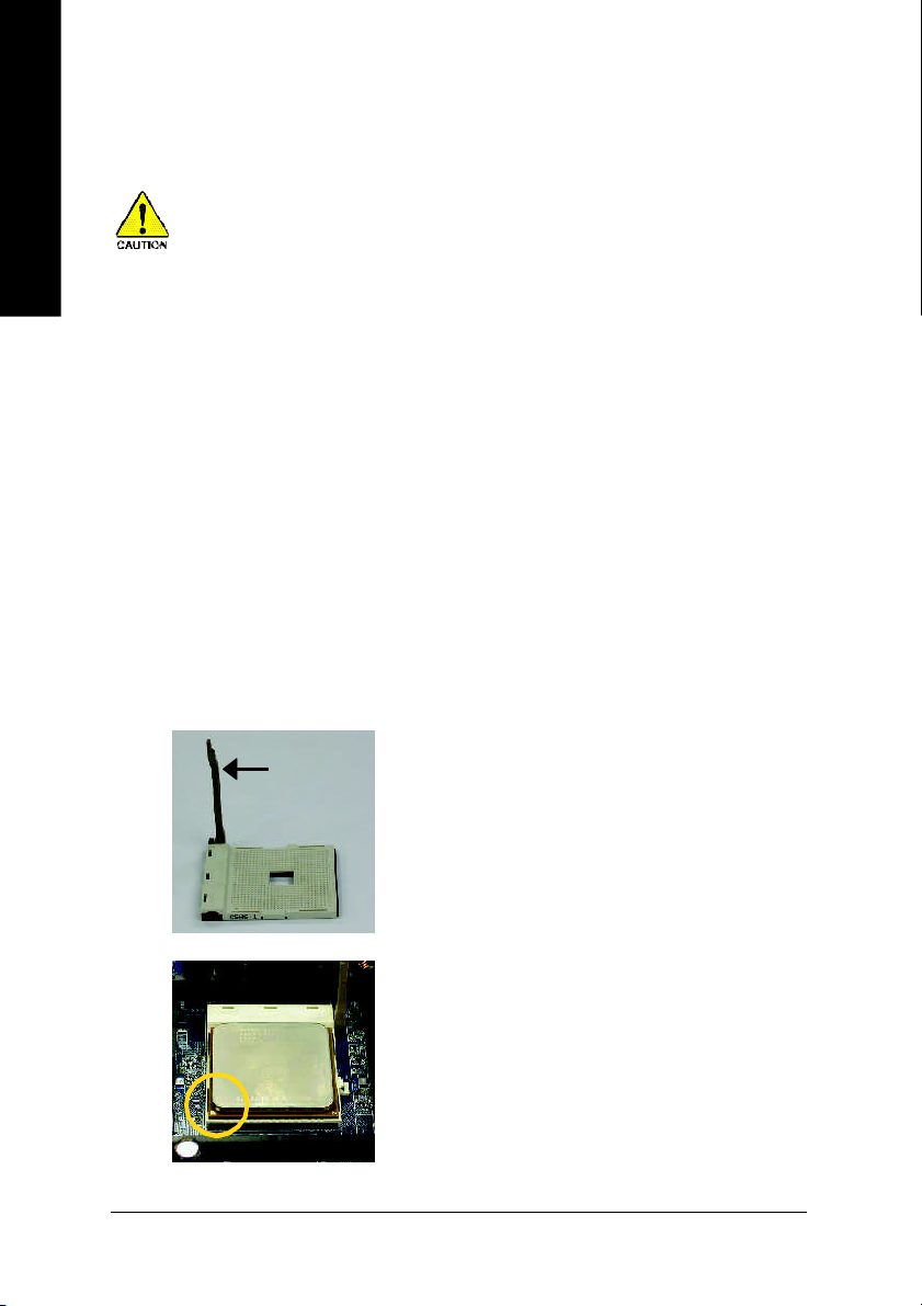
The installation of the processor and cooling fan is performed in four main steps:
Step1-1. F irs t, c hec k th e pro ces sor p ins to se e that non e ar e b ent. Mov e the so cke t lev er to the
1. Please make sure the CPU type is supported by the motherboard.
2. The processor will overheat without the heatsink and/or fan, resulting in permanent
irreparable damage.
3. If you do not match the CPU socket Pin 1 and CPU cut edge well, it will cause improper
installation. Please change the insert orientation.
4. Apply thermal grease between the processor and cooling fan.
5. Never run the processor without the heatsink properly and firmly attached. Permanent
damage will result.
6. Please set the CPU host frequency in accordance with your processor's specifications.
We don't recommend you to set the system bus frequency over the CPU's specification
because these specific bus frequencies are not the standard specifications for CPU,
chipset and most of the peripherals. Whether your system can run under these specific
bus frequencies properly will depend on your hardware configurations, including CPU,
Memory, Cards… etc.
unlocked p osition as shown in Figu re 1.(90o to the plane of the m otherboard) p rior to inserting
the pr ocess or. The pin 1 locatio n is de signa ted o n the pro cesso r by a copp er triangl e that
matches up to a triangle on the so cket as shown in Figure 2. Align the proc essor to the socket
and g ently lower it in to pla ce. D o not force the p rocess or into the so cket.
Figure 1.
Socket Lever
Pull the lever to the 90 -degre e dire ctly.
GA-K8VM 800M Motherboard
Figure 2.
Pi n 1 loca tion o n the Soc ke t a nd Pro ces sor . Mov e the
sock et leve r to the lock ed po sition whil e hol ding pressu re
on the cen ter of the proc essor.
- 14 -
Page 15
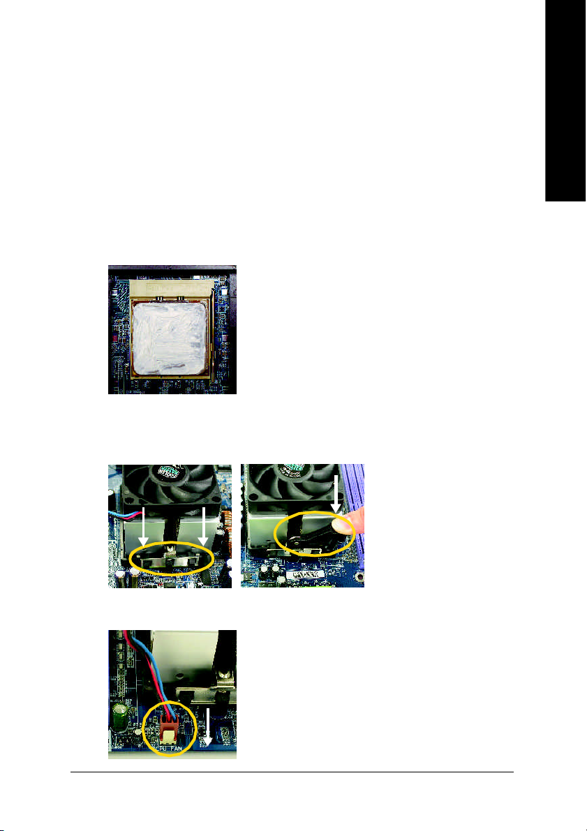
Step1-2. When the pro cessor is in stalled in the socket, apply thermal grease to the processor (as shown
in Figu re 3) pri or to installing the h eatsink. Phase ch ange m aterials dev elop strong a dhesive
forces between the hea tsink an d proce ssor. Remo ving the hea tsink u nder su ch cond i-
tion s ca n cause the p roc esso r to be r emoved from the socket without moving the
socket lever to the u nlocked p osition a nd t hen damag e the pr ocesso r pi ns or socket
contact s.
** We r ecom me nd you to a pply the therm al tape to provid e better he at co nduction between
your C PU and h eatsink. (Th e CP U cooli ng fan m ight stick to the CPU due to the ha rdening of
the thermal p aste. During this c ondition if you try to remove the cooling fan, y ou mi ght pull the
processo r out of the CPU socket alone with the cooling fan, and migh t damage the pr ocessor.
To av oid this from happen ing, we sugge st you to either use therma l tape ins tead o f therm al
paste, orre mov e the cooli ng fan with extrem e ca ution.)
Figure 3.
Applic ation of thermal grease to the proc essor.
Step 1-3.O nce the therm al gre ase has bee n applie d to the proces sor, the he atsink c an be a ttached to
the processor. Align the heatsink assem bly with the supp ort fram e m ating with the backer plate
standoffs a s s hown in Fi gure 4 & 5.
English
Figure 4 & 5.
Alig nm ent of heatsi nk as sem bly
with stand offs.
Step 1-4 . C onnect the fan power wires to the header on the m otherboar d as s hown in Figu re 6.
Figure 6.
Conn ecting the fan power wire s.
- 15 -
Hardware Installation Proc ess
Page 16
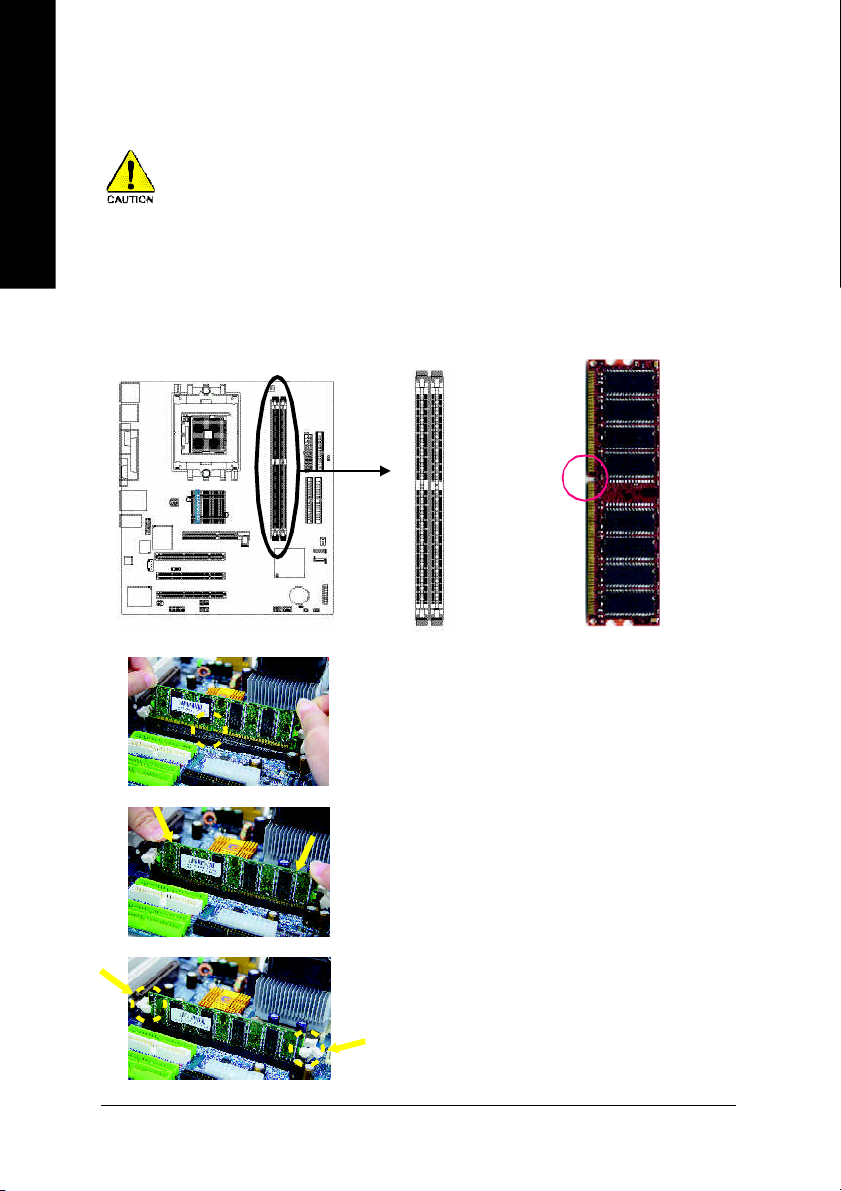
Step 2: Install Memory Modules
English
The motherboard has 2 dual inline memory module (DIMM) sockets. The BIOS will automatically
detects memory type and size. To install the memory module, just push it vertically into the DIMM
socket. The DIMM module can only fit in one direction due to the notch. Memory size can vary
between sockets.
Before installing the memory modules, adhere to the following warning:
1. When RAM_LED is ON, do not install / remove DIMM from socket.
2. Please note that the DIMM module can only fit in one direction due to
the one notch. Wrong orientation will cause improper installation.
Please change the insert orientation.
Notch
1. The DIM M s oc ket ha s a notc h, so the DIMM
me mor y mo dule can o nly fit in one d irection.
2. Insert the DIMM memory module vertically into
the DIM M soc ket. The n pus h i t down.
3. Close the plastic clip at both edges of the DIM M
sockets to lo ck the DIMM m odule.
Reve rse the installation steps when yo u wish to
rem ove the DIMM modu le.
DDR
GA-K8VM 800M Motherboard
- 16 -
Page 17
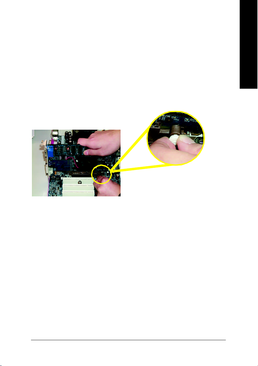
Step 3: Install expansion cards
1. Read the related expansion card's instruction document before install the expansion card into the
computer.
2. Remove your computer's chassis cover, screws and slot bracket from the computer.
3. Press the expansion card firmly into expansion slot in motherboard.
4. Be sure the metal contacts on the card are indeed seated in the slot.
5. Replace the screw to secure the slot bracket of the expansion card.
6. Replace your computer's chassis cover.
7. Power on the computer, if necessary, setup BIOS utility of expansion card from BIOS.
8. Install related driver from the operating system.
AGP Card
English
Please carefully pull out the small white-drawable bar at the end of the AGP slot when you try to install
/ uninstall the AGP card. Please align the AGP card to the onboard AGP slot and press firmly down on
the slot. Make sure your AGP card is locked by the small white-drawable bar.
- 17 -
Hardware Installation Proc ess
Page 18
Step 4: Install I/O Peripherals Cables
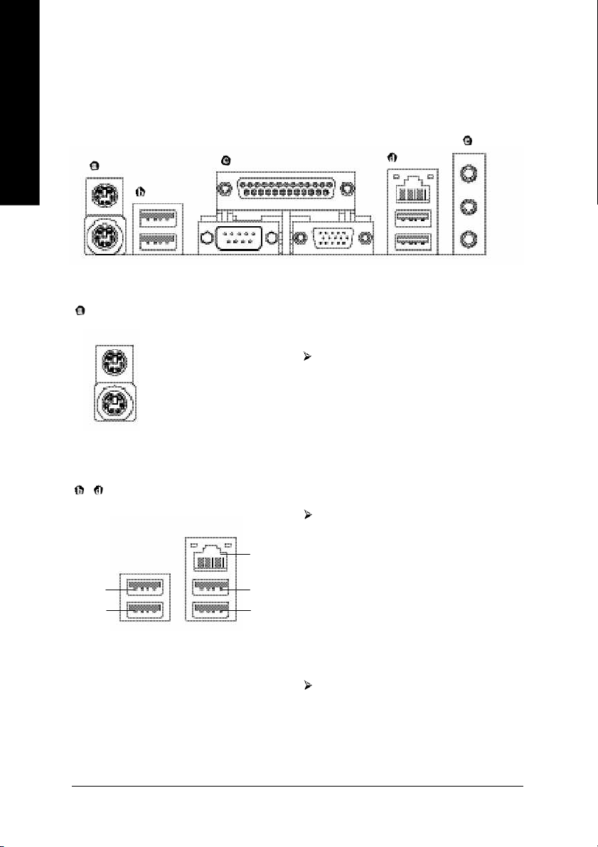
Step 4-1: I/O Back Panel Introduction
English
PS/2 Keyboard and PS/2 Mouse Connector
PS/2 Mouse Connector
(6 pin Female)
PS/2 Keyboard Connector
(6 pin Female)
/ USB/LAN Connector
USB 0
USB 1
LAN
USB 2
USB 3
This connector supports standard PS/2
keyboard and PS/2 mouse.
Before you connect your device(s) into USB
connector(s), please make sure your device
(s) such as USB keyboard,mouse, scanner,
zip, speaker...etc. Have a standard USB
interface. Also make sure your OS supports
USB controller. If your OS does not support
USB controller, please contact OS vendor for
possible patch or driver upgrade. For more
information please contact your OS or device
(s) vendors.
LAN connector is fast Ethernet with 10/100
Mbps speed.
GA-K8VM 800M Motherboard
- 18 -
Page 19
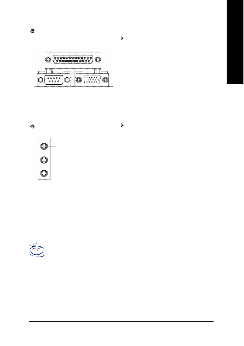
Parallel Port , Serial Port and VGA Port (LPT/COMA/VGA)
This connector supports 1 standard COM port,
Parallel Port (25 pin Fema le)
COMA VG A
Serial Port
(9 pin Male)
VGA Port
(15 pin Female)
1 Parallel port and 1 VGA port. Device like
printer can be connected to Parallel port;
mouse and modem etc can be connected to
Serial ports.
English
Audio Connectors
Line In
Line Out
MIC In
After install onboard audio driver, you may connect speaker to Line Out jack, microphone to MIC
In jack. Device like CD-ROM,walkman etc. can
be connected to Line-In jack.
Please note:
You are able to use 2-/4-/6-channel audio feature
by S/W selection.
If you want to enable 6-channel function, you
have 2 choose for hardware connection.
Method1:
Connect "Front Speaker" to "Line Out"
Connect "Rear Speaker" to "Line In"
Connect "Center and Subwoofer" to "MIC In ".
Method2:
You can refer to page 27, and contact your
nearest dealer for optional SUR_CEN cable.
If you want the detail information for 2-/4-/6-channel audio setup
installation, please refer to page 65.
- 19 -
Hardware Installation Proc ess
Page 20
Step 4-2: Connectors Introduction
English
31 2
5
10
6
11
12
4
14
16
1) ATX_12V
2) ATX (Power Connector)
3) CPU_FAN
4) SYS_FAN
5) FDD
6) IDE1 / IDE2
7) SATA0 / SATA1
8) F_PANEL
9) PWR_LED
10) RAM_LED
11) F_AUDIO
7
22
8
21
13
17
19
15
20 918
12) SUR_CEN
13) SPDIF_IO
14) CD_IN
15) F_USB1 / F_USB2
16) IR
17) GAME
18) INFO_LINK
19) COMB
20) CLR_CMOS
21) C I
22) BAT
GA-K8VM 800M Motherboard
- 20 -
Page 21
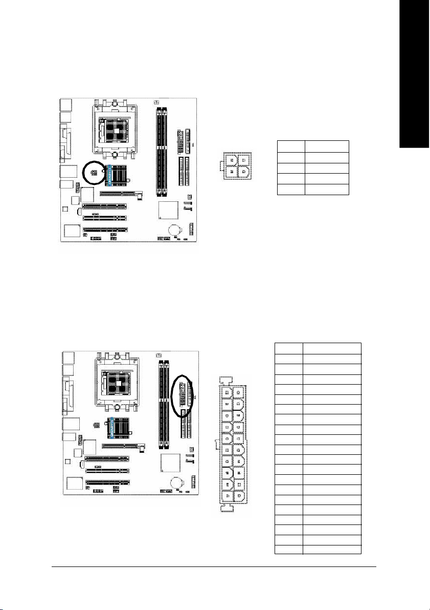
1) ATX_12V (+12V Power Connector)
This c onnector ( ATX_12V) supp lies the C PU oper ation voltage (V core).
If this "ATX_1 2V con nector" i s no t connected, system c annot boo t.
English
432
1
Pin No. Definition
1 GND
2 GND
3 +12V
4 +12V
2) ATX (ATX Power Connector)
AC p ower cord shou ld onl y be connected to you r power s upply u nit after ATX power cab le a nd
other rela ted devices are firmly connected to the mo therboard.
11
20
1
10
Pin No . D efinition
1 3. 3V
2 3. 3V
3 GND
4 VCC
5 GND
6 VCC
7 GND
8 Po wer Go od
9 5V S B (stand by +5V)
10 +12V
11 3.3V
12 -12V
13 GND
14 PS_ON(s oft on/off)
15 GND
16 GND
17 GND
18 -5V
19 VCC
20 VCC
- 21 -
Hardware Installation Proc ess
Page 22
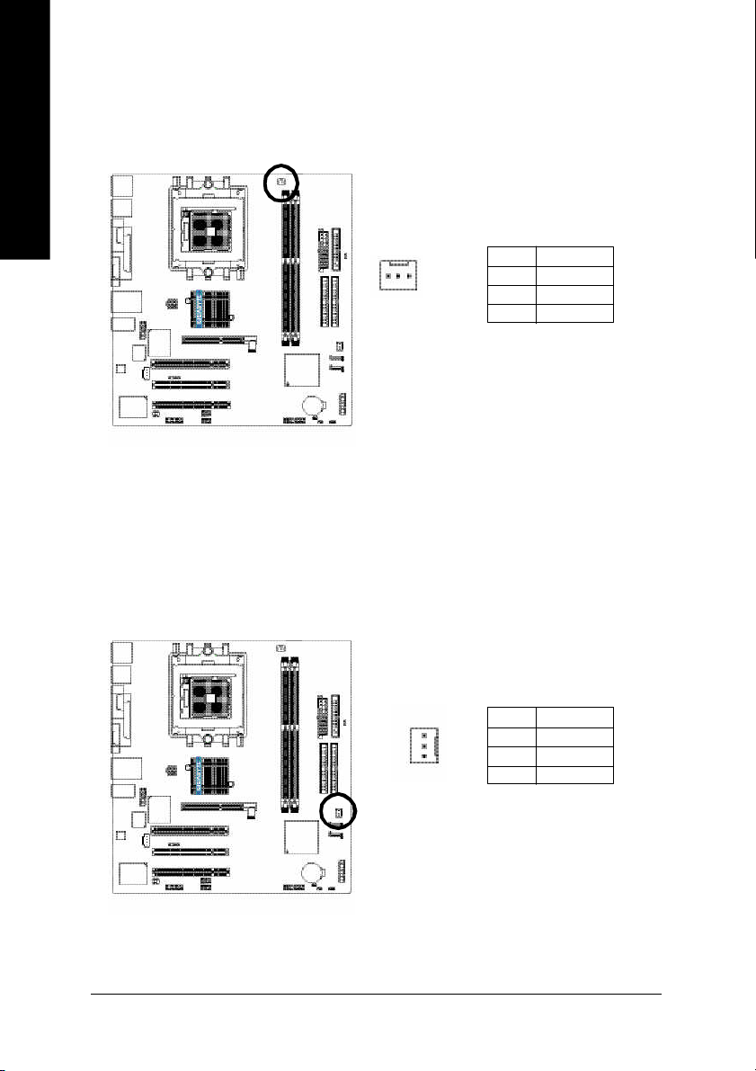
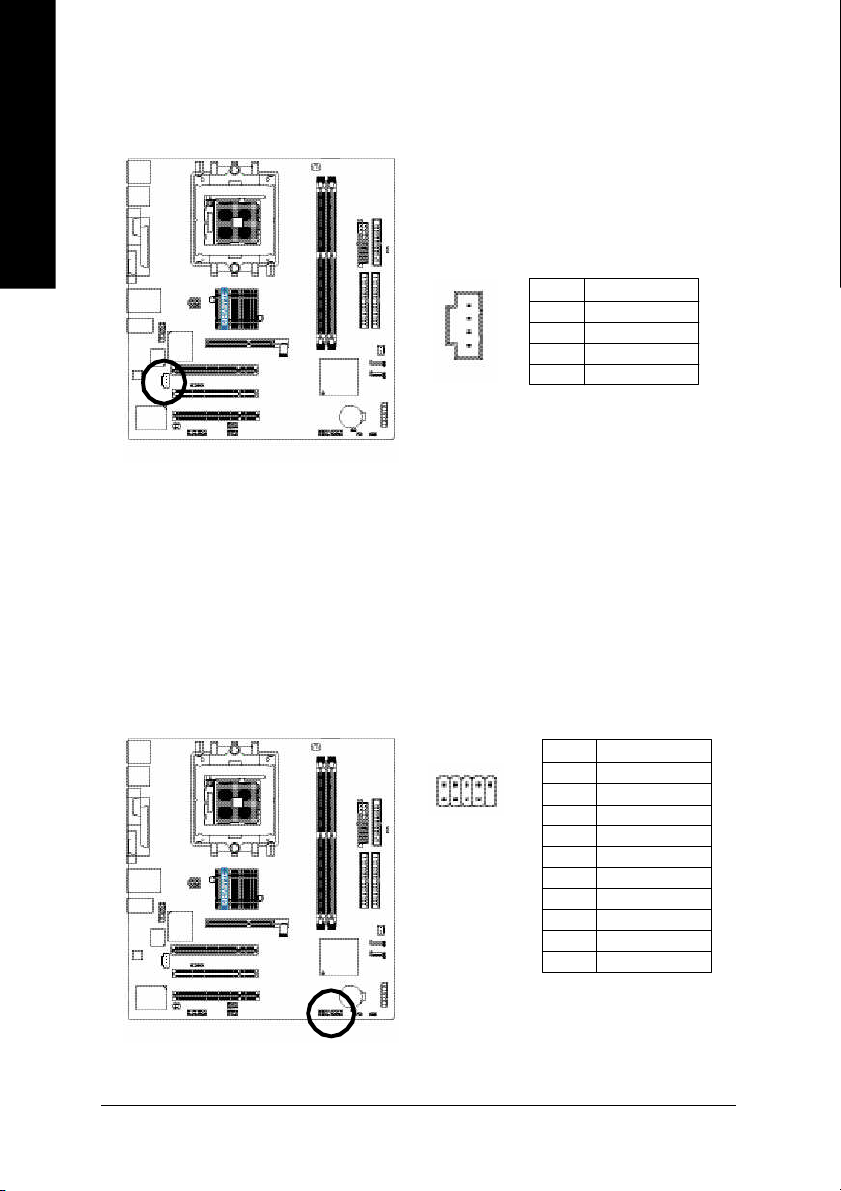
3) CPU_FAN (CPU Fan Connector)
English
4) SYS_FAN (System Fan Connector)
Pleas e note, a proper ins tallation of the CPU coo ler is essential to pre vent the CPU from runni ng
unde r abn orm al con dition or dam age d by overh eating . T he C PU fan con nector supports Ma x.
current up to 600 m A.
Pin No. Definition
1
Thi s conn ector allo ws y ou to l ink with the c ool ing fan on the s ystem cas e to lower the sys tem
temperature.
1 GND
2 +12V
3 Sense
GA-K8VM 800M Motherboard
- 22 -
1
Pin No. Definition
1 GND
2 +12V
3 Sense
Page 23
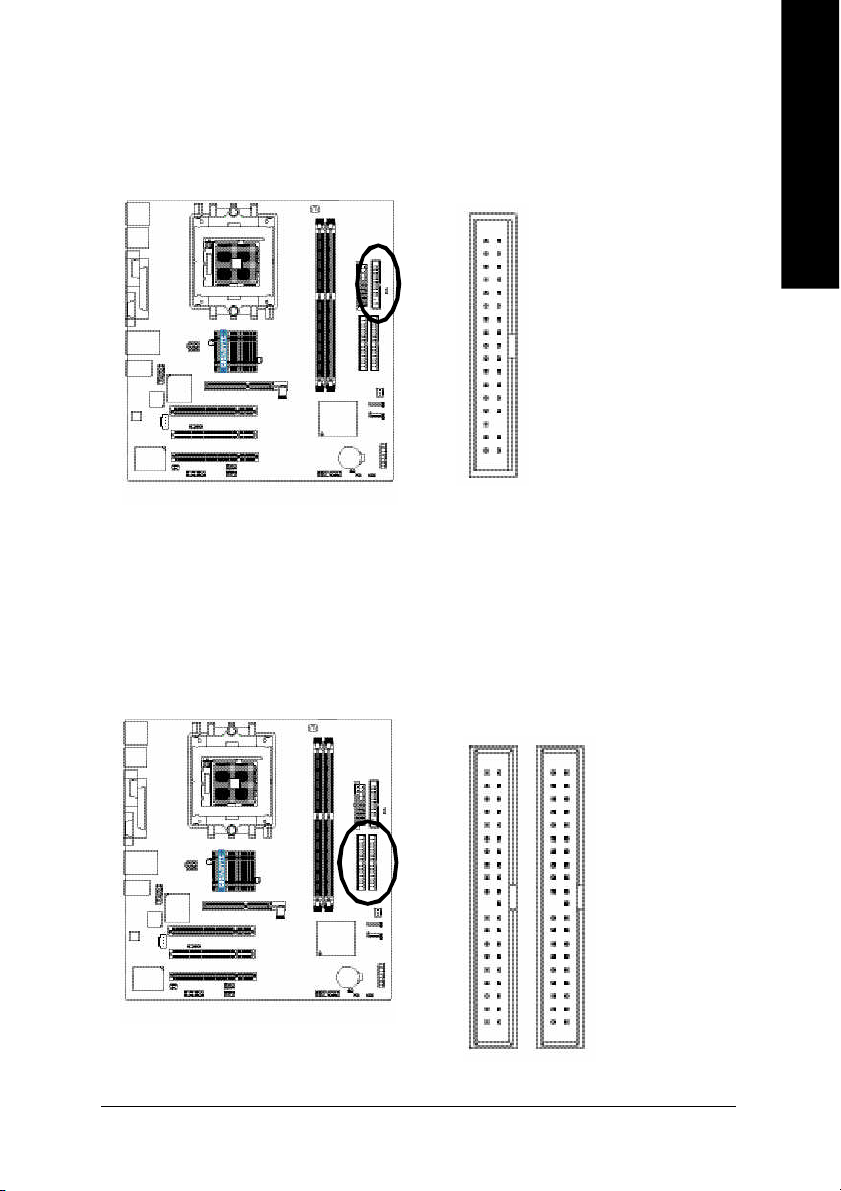
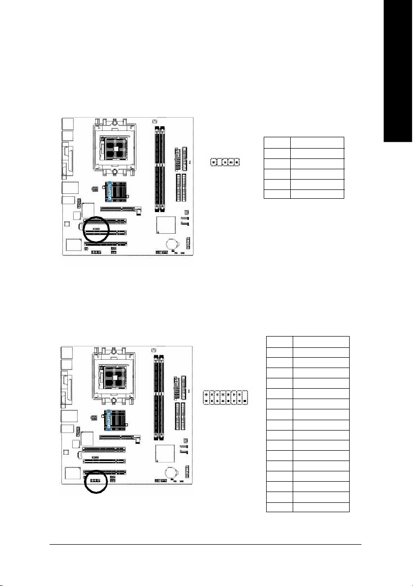
5) FDD (Floppy Connector)
Pleas e conne ct the floppy drive ribbon cab les to FD D. It supp orts 360K, 1.2M , 720 K, 1.44M and
2.8 8M bytes flo ppy disk typ es.
The r ed stripe of the ri bbon ca ble m ust be the sam e side with the Pin1.
English
34
2
6) IDE1 / IDE2 (IDE1 / IDE2 Connector)
Impor tant Notice:
Pleas e conne ct first hard disk to IDE1 an d conne ct CD-ROM to IDE2.
The r ed stripe of the ri bbon ca ble m ust be the sam e side with the Pin1.
33
1
3940
- 23 -
2
IDE2
1
IDE1
Hardware Installation Proc ess
Page 24
7) SATA0 / SATA1 (Serial ATA Connector)
English
8) PWR_LED
You can connect the Seri al ATA de vice to this con nector. If you wish to use RAID function , plea se
use i t in unity with BIOS and install the co rrect dr iver to h ave prop er ope ration.
Pin No. Definition
1 GND
1
7
2 TXP
3 TXN
4 GND
5 RXN
6 RXP
7 GND
PWR_ LED is con nect with the system power indica tor to ind icate whether the sys tem is on/ off.
It will bl ink when the system enters susp end m ode. If yo u use du al color LED, p ower LED will turn
to another colo r.
GA-K8VM 800M Motherboard
- 24 -
1
Pin No. Definition
1 MPD+
2 MPD-
3 MPD-
Page 25
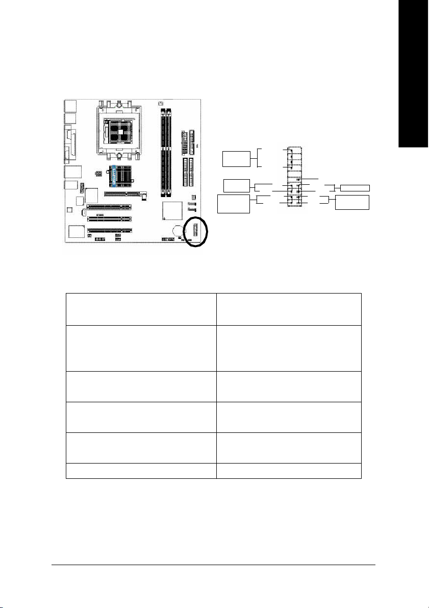
9) F_PANEL (2 x 10 pins Connector)
Plea se co nnect the po wer L ED, P C spe aker, re set switch and power s witch e tc. of your chass is
front panel to the F_ PANEL connec tor ac cordin g to the pin assignm ent belo w.
1 92 0
Speak er
Connect or
Sof t Po wer
Connect or
Messa ge L ED/
Po wer/
Slee p LED
HD (IDE Hard Disk Active LED) Pin 1: LED anode(+)
Pin 2: LED cathode(-)
SPEAK (Speaker Connector) Pin 1: V CC(+)
Pin 2- Pin 3: NC
Pin 4: Data(-)
RES (Reset Switch) Open: Normal Operation
Close: Reset Hardware System
PW (Soft Power Connector) Open: Normal Operation
Close: Power On/Off
MSG(Message LED/ Power/ Sleep LED) Pin 1: LED anode(+)
Pin 2: LED cathode(-)
N C N C
SPEAK-
SPEAK+
PW+
MSG+
PW-
MSG-
NC
1
RES+
RES-
HD -
IDE Har d Dis k
HD +
2
1
Act ive LE D
English
Res et Swi tch
- 25 -
Hardware Installation Proc ess
Page 26
10) RAM_LED
English
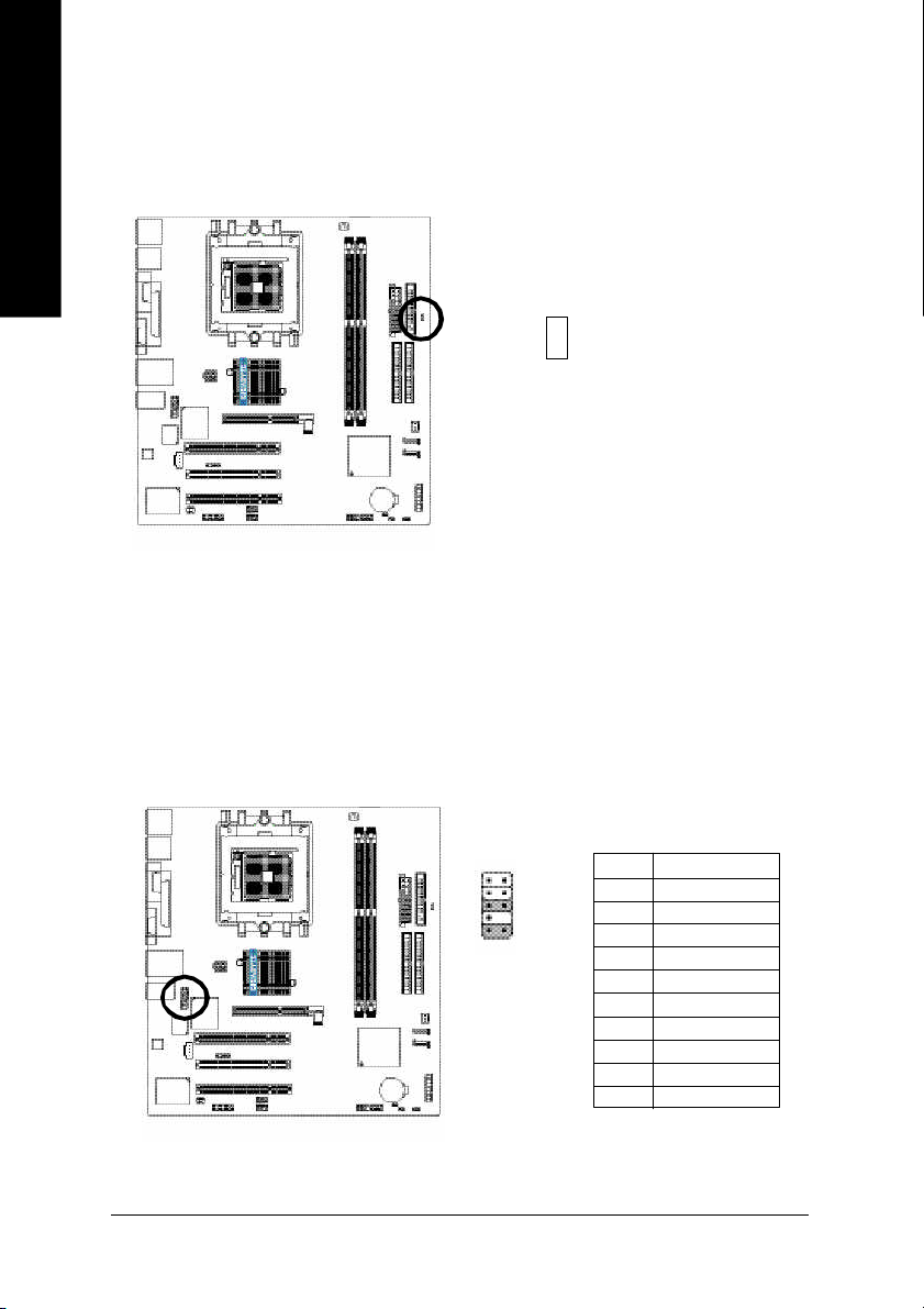
11) F_AUDIO (Front Audio Connector)
Do not rem ove m em ory m odules while RAM _LED is on. It mig ht cause shor t or other unexpec ted
dam age s due to the s tand by vo ltage. Rem ove mem ory mo dules o nly whe n AC po wer c ord is
disco nnected.
_
+
If you want to use Front Au dio c onnector , you must rem ove 5-6, 9-10 Jumper.
In order to utilize the front audio header, your chassis must have front audio connector. Also pl ease
mak e sure the pin as sigme nt on the cable is the sam e as the pin assigm ent on the MB h eader. To
find ou t if the ch assis you are buying s upport fron t audio connector, please contact your deale r.
Plea se no te, y ou ca n have the a lternativ e of usi ng front aud io conn ector o r of using r ear a udio
conn ector to play soun d.
GA-K8VM 800M Motherboard
- 26 -
2
1
10
9
Pin No. Definition
1 MIC
2 GND
3 MIC_BIAS
4 Power
5 Front Audio (R)
6 Rear Audio (R)
7 Reserved
8 No Pin
9 Front Audio (L)
10 Rear Audio (L)
Page 27
12) SUR_CEN (Surround Center Connector)
Pleas e contact your neare st dealer for o ptional SUR_CEN c able.
Pin No. Definition
1
2
6
5
1 SUR OUTL
2 SUR OUTR
3 GND
4 No Pin
5 CENTER_OUT
6 BASS_OUT
13) SPDIF_IO (SPDIF In / Out Connector)
The S PDIF o utput is cap able o f prov iding digital audio to extern al spe akers or com presse d AC3
data to an e xterna l Do lby Digital Deco der. U se thi s feature only whe n yo ur stere o sy stem h as
dig ital i np ut functi on. B e ca refu l with the pol ar ity of the SPDIF _IO co nne ctor. Che ck the pin
assig nmen t carefully while y ou con nect the SPDIF cabl e, inco rrect con nection be tween the cab le
and co nnector will m ake the dev ice una ble to work or eve n dam age it. F or o ptional SPD IF cable,
pleas e con tact your loc al dea ler.
English
- 27 -
Pin No. Definition
1
5
2
6
1 VCC
2 No Pin
3 SPDIF
4 SPDIFI
5 GND
6 GND
Hardware Installation Proc ess
Page 28
14) CD_IN (CD In Connector)
English
Connec t CD-ROM or DVD -ROM audio out to the conn ector.
1
Pin No. Definition
1 CD-L
2 GND
3 GND
4 CD-R
15) F_USB1 / F_USB2 (Front USB Connector)
Be ca reful with the pol arity of the front USB c onnector . Chec k the pin assign me nt car efully whi le
you con nect the front USB c able, in correct conne ction between the cable and connector will m ake
the dev ice unab le to work or even dam age i t. Fo r option al front USB cable, plea se contact yo ur
local d ealer.
2 10
1 9
Pin No. Definition
1 Power
2 Power
3 USB Dx-
4 USB Dy-
5 USB Dx+
6 USB Dy+
7 GND
8 GND
9 No Pin
10 NC
GA-K8VM 800M Motherboard
- 28 -
Page 29
16) IR
Mak e sure the p in 1 on the IR device is aling with pin one the conn ector. To enable the IR function
on the board , you are required to purchase an option IR m odule. Be careful with the polarity of the
IR/CIR or IR con nec tor. Check the pin ass ignm ent carefully while you connect the IR cable,
incorrec t connection between the cable and co nnector will mak e the device una ble to work or even
dam age it. F or optional IR ca ble, p lease c ontact you r loca l deale r.
Pin No. Definition
1
1 VCC(+5V)
2 No Pin
3 IR Data Input
4 GND
5 IR Data Output
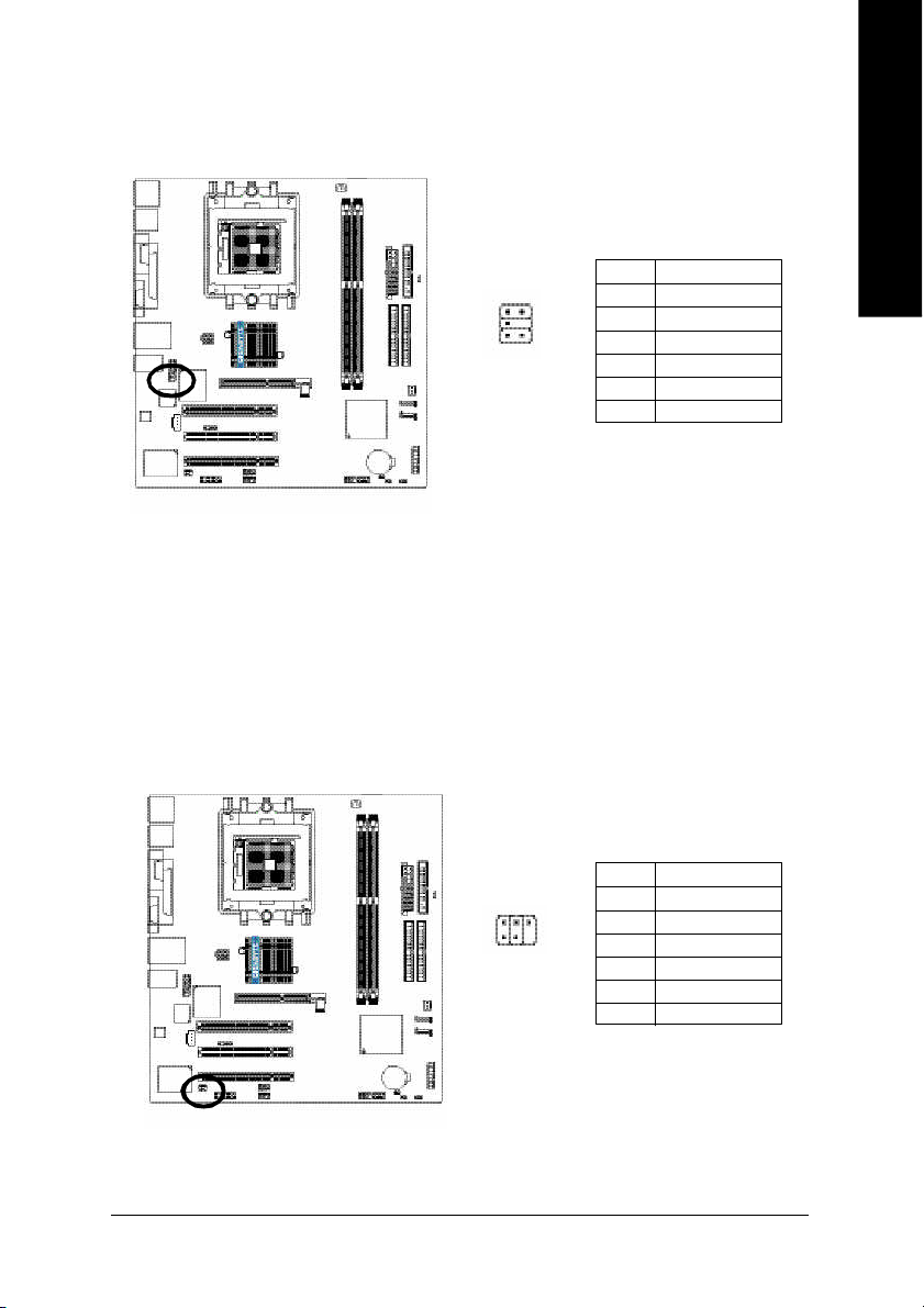
17) GAME (Game Connector)
This conn ector supp orts jo ystick, M IDI keyb oard and other re late au dio dev ices. Chec k the pin
assig nme nt while you c onnect the gam e cables. Please contact your nearest dealer for optional
gam e cable s.
Pin No. Definition
1 VCC
2 GRX1_R
3 GND
2
1
16
15
4 GPSA2
5 VCC
6 GPX2_R
7 GPY2_R
8 MSI_R
9 GPSA1
10 GND
11 GPY1_R
12 VCC
13 GPSB1
14 MSO_R
15 GPSB2
16 No Pin
English
- 29 -
Hardware Installation Proc ess
Page 30

18) INFO_LINK
English
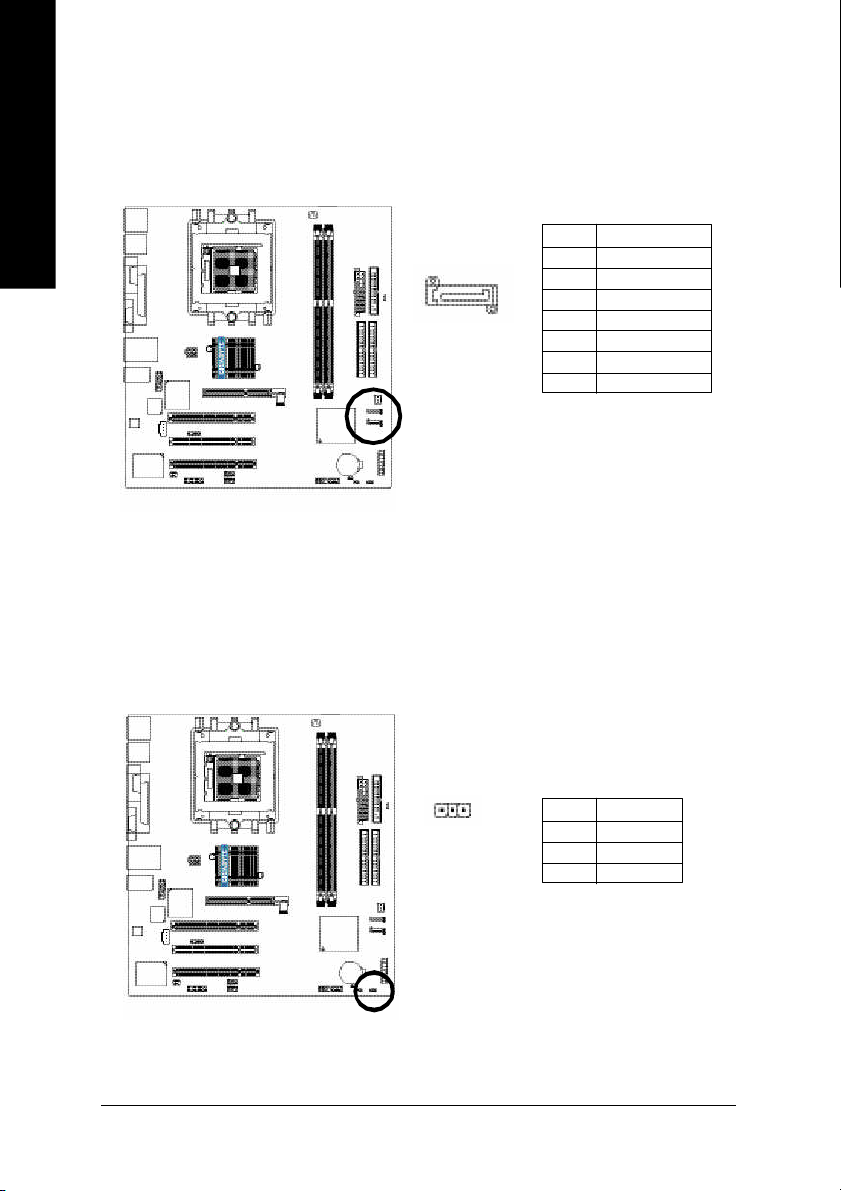
19) COMB (COM B Connector)
This c onnector al lows you to connec t some external de vices to pr ovide you e xtra function. Che ck
the pin ass ignm ent while you connect the external device cable. Please contact your nearest
deale r for option al external devic e cabl e.
Pin No. Definition
1 SMBCLK
2
10
9
1
2 VCC
3 SMBDATA
4 GPIO
5 GND
6 GND
7 No Pin
8 NC
9 +12V
10 +12V
Be car eful with the pol arity of the COM B connector. Check the pin ass ignm ent car efully while y ou
conn ect the COM B cable, incorrect connection between the cable and connector will make the
devi ce un able to wor k or ev en dam age it. For o ptiona l C OM B cab le, please contact your loc al
dealer.
2
10
9
1
Pin No. Definition
1 NDCDB2 NSINB
3 NSOUTB
4 NDTRB-
5 GND
6 NDSRB-
7 NRTSB-
8 NCTSB-
9 NRIB10 No Pin
GA-K8VM 800M Motherboard
- 30 -
Page 31

20) CLR_CMOS (Clear CMOS)
You m ay clear the CM OS data to i ts default values by this ju mpe r. To cl ear CM OS, tem por arily
short 1-2 p in. Default doesn 't include the "S hunter" to prevent from i mpro per use this jump er.
English
1
1
Open: Norm al
Short: Clear CMOS
21) CI (Chassis Intrusion, Case Open)
This 2-pin connector al lows your system to en able o r d isable the "cas e op en" item in BIOS i f the
system case begin rem ove.
Pin No. Definition
1
1 Signal
2 GND
- 31 -
Hardware Installation Proc ess
Page 32

22) BATTERY
English
+
CAUTION
Da nge r of e xp los io n if batte ry i s inco rr ectl y
replace d.
Repl ace on ly with the s am e or equivale nt type
recom men ded by the m anufacturer.
Di sp ose of us ed b atte ri es a cc or di ng to the
ma nufacturer's i nstructions.
If you want to era se CM OS. ..
1. Turn OFF the com puter and unplug the power cord.
2. R em ove the b attery, wait for 30 sec ond.
3. R e-ins tall the battery.
4. Pl ug the power cor d and turn O N the com puter.
GA-K8VM 800M Motherboard
- 32 -
Page 33

English
- 33 -
Hardware Installation Proc ess
Page 34

English
GA-K8VM 800M Motherboard
- 34 -
Page 35

Chapter 3 BIOS Setup
BIOS Setup is an overview of the BIOS Setup Program. The program that allows users to modify the
basic system configuration. This ty pe of information is stored in battery-b acked CM OS RAM so that it
retains the Setup information when the power is turned off.
ENTERING SETU P
Powering ON the computer and pressing <Del> immediately will allow you to enter Setup. If y ou require
more a dvance d BIOS settings, please g o to " Ad vanced BIOS" setting me nu. To en ter
Advanced BIOS setting menu, press "Ctrl+F1" key on the BIOS screen.
When setting up BIOS for the first time, it is recommended that you save the current BIOS to
a disk in the event that BIOS needs to be reset to its original settings. If you wish to upgrade
to a new BIOS, either Gigabyte's Q-Flash or @BIOS utility can be used.
Q-Flash allows the user to quickly and easily update or backup BIOS without entering the
operating system.
@BIOS is a Windows-based utility that does not require users to boot to DOS before
upgrading BIOS but directly download and update BIOS from the Internet.
CONTROL KEYS
< > Move to previous item
< > Move to next item
< > Move to the item in the left hand
< > Mov e to the item in the right hand
<Enter> Select Item
<Esc> Main Menu - Quit and not save changes into CMOS Status Page Setup Menu and
Option Page Setup Menu - Exit current page and return to Main M enu
<+/PgUp> Increase the numeric value or make changes
<-/PgDn> Decrease the numeric value or make changes
<F1> General help, only for Status Page Setup Menu and Option Page Setup Menu
<F2> Item Help
<F3> Reserved
<F4> Reserved
<F5> Restore the previous CM OS value from CMOS, only for Option Page Setup Menu
<F6> Load the file-safe default C MOS value from BIOS default table
<F7> Load the Optimized Defaults
<F8> Q-Flash utility
<F9> System Information
<F10> Save all the CM OS changes, only for Main Menu
English
- 35 -
BIOS Setup
Page 36

M ain Menu
The on-line description of the highlighted setup function is displayed at the bottom of the screen.
Status Page Setup Menu / Option Page Se tup Menu
English
Press F1 to pop up a small help w in dow that descr ibes the appro priate keys to use and the possible
selections for the highlighted item. To ex it the Help Window press <Esc>.
The Main Menu (For example: BIOS Ver. : D8)
Once you enter Aw ard BIOS CMOS Setup Utility, the Main M enu (as figure below) w ill appear on the
screen. The M ain Menu allows you to select from eight setup functions and two ex it choices. Use arrow
keys to select among the items and press <Enter> to accept or enter the sub-menu.
CMOS Setup Utility -Copyright (C) 1984 -2004 Award Soft ware
} Standard CM OS Features
} Advanced BI OS Features
} Inte grated Peripherals
} P owe r Managem ent S etup
} P nP/PCI Con figurations
} P C Health Status
} Frequ ency/Voltage Control
ESC: Quit higf: Selec t Item
F8: Q- Flash F10: Save & Exit Setup
Time, Date, Har d Disk Ty pe...
Load Fail-Safe Defa ults
Load Optimized Defa ults
Set Supervisor P assword
Set U ser P ass word
Save & Exit S etup
Exit Without Saving
If you can't find the se tting you want, please press "C trl + F1" to search the advanced option
hidden.
l Standard CMOS Features
This setup page includes all the items in standard compatible BIOS.
l Advanced BIOS Features
This setup page includes all the items of Award special enhanced features.
l Integrated Peripherals
This setup page includes all onboard periphe rals.
l Power M anag ement Setup
This setup page includes all the items of Green function fea tures.
l PnP/PCI Configurations
This setup page includes all the configurations of PCI & PnP ISA resources.
- 36 -GA-K8VM800M Motherboard
Page 37

l PC Health Status
This setup page is the System auto detect Temperature, voltage, fan, speed.
l Frequency/V oltage Control
This setup page is control CPU’s clock and frequency ratio.
l Load Fail-Safe Defaults
Fail-Safe Defaults indicates the value of the sys tem parameters which the system would be in safe
configuration.
l Load Optimiz ed Defaults
Optimized Defaults indicates the value of the system parameters which the sy stem w ould be in
best performance configuration.
l Set Supervisor Password
Change, set, or disable pas sw ord. It allow s you to limit access to the system and Setup, or just
to Setup.
l Set User Passw ord
Change, set, or disable pass w ord. It allows you to limit access to the system.
l Save & Exit Setup
Save C M OS value settings to CMOS and ex it setup.
l Exit Without Saving
Abandon all CM OS value changes and exit setup.
English
- 37 -
BIOS Setup
Page 38

Standard CMOS Features
English
The date format is <week>, <month>, <day>, <y ear>.
military-time clock. For ex ampl e, 1 p.m. is 13:00:00.
computer. There are two types: auto type, and manual type. Manual type is user-definable; Auto type
which w ill automatically d etect HDD type.
Note that the spec ifications of your driv e must match w ith the driv e table. The hard disk w ill not work
properly if y ou enter improper information for this category .
If you select User Type, related information wil l be asked to enter to the followin g items. E nter the
information directly from the keyboard and press <Enter>. Such information should be prov ided i n the
documentation form your hard disk v endor or the system manufacturer.
If a hard disk has not been installed, select NONE and press <Enter>.
CMOS Setup Utility -Copyright (C) 1984 -2004 Award Soft ware
Date (m m:dd:yy ) Tue, Jan 27 2004
Time (hh:m m :ss) 22:31:24
} IDE Primary M aster [None]
} IDE Primary S lave [None]
} IDE Secondary Master [None]
} IDE Secondary Slave [None]
Drive A [1.44M, 3.5"]
Drive B [None]
Floppy 3 Mode S uport [Disabled]
Holt On [All, But Keyb oard]
Base Memory 640K
Exte nded Me mory 127M
Total Memory 128M
higf: Move Enter: Select +/-/P U/P D: Value F10: Save ESC: Exit F1: General Help
F5: P revious Values F6: Fa il-Save De fault F7: Optimized Defaults
Standard CMOS Features
Item Help
Menu L evel}
Change the day, m onth,
year
<We ek>
Sun. to Sat.
<Month>
Jan. to Dec.
<Day>
1 to 31 (or ma ximum
allowe d in the m onth)
<Ye ar>
1999 to 2098
Date
Week The we ek, from Sun to Sat, determined by the BIOS and is displayed only
Month The month, Jan. Through Dec.
Day The day, from 1 to 31 (or the maxi mum allowed in the month)
Year The year, from 1999 through 2098
Time
The times format in <hour> <m inu te> <second>. The time is c alc ulated base on the 2 4-hour
IDE Primary Master, Slave / IDE Secondary Master, Slave
The category id entifies the types o f hard d isk from driv e C to F that has been i nsta lled in the
Cylinder Number of cylinders
Head Number of heads
Precomp Write precomp
Landing Zone Landing zone
Sector Number of sectors
- 38 -GA-K8VM800M Motherboard
Page 39

Drive A / Dri v e B
The category ide ntifies the types of floppy di sk drive A o r drive B that has been installed in the
computer.
None No fl oppy driv e installed
360K, 5.25" 5.25 inch PC-type standard driv e; 360K by te capacity.
1.2M, 5.25" 5.25 inch AT-type high- density driv e; 1.2M byte capacity
(3.5 inch whe n 3 Mode is Enabled).
720K, 3.5" 3.5 inch double-sided dr ive; 720K byte capacity
1.44M, 3.5" 3.5 inch double-sided dri ve; 1.44M byte capacity.
2.88M, 3.5" 3.5 inch double-sided dri ve; 2.88M byte capacity.
Floppy 3 Mode Support (f or Japan Area)
Disabled Normal Floppy Drive. (Default v alue)
Driv e A Drive A is 3 mod e Floppy Drive.
Driv e B Drive B is 3 mod e Floppy Drive.
Both Drive A & B are 3 mode Floppy Drives.
Halt on
The category determines w hether the computer w ill stop if an error is d etected d uring power up.
No Errors The sy stem boot will not stop for any error tha t may be detected and you
will be promp ted.
All Errors Whenever the BIOS detects a non-fatal error the system will be stopped.
All, But Keyboard The sy stem boot will not stop for a key board error; it will stop for all other
errors. (Default value)
All, But Diskette The system boot will not stop for a disk error; it w ill stop for all other errors.
All, But Disk/Key The system boot will not stop for a keyboard or disk error; it will stop for all
other errors.
Memory
The category is display -only w hi ch is determined by POST (Pow er On Self Test) of the BIOS.
Base Memory
The POST of the BIOS will determine the amount of base (or conv entional) memory installed
in the system.
The value of the base memory is typically 512K for sy stems with 512K memory installed on
the motherboard, or 640K for systems with 640K or more memory installed on the motherboard.
Extended Memory
The BIOS determines how much ex tended me mory is present during the POST.
This is the amount of memory located abov e 1 MB i n the CPU's memory address map.
English
- 39 -
BIOS Setup
Page 40

Advanced BIOS Features
English
CMOS Setup Utility -Copyright (C) 1984 -2004 Award Soft ware
First Boot Device [Floppy]
Second Boot Device [HDD -0]
Thir d Boot D evice [CDR OM]
Password C heck [Set up]
higf: Move Enter: Select +/-/P U/P D: Value F10: Save ESC: Exit F1: General Help
F5: P revious Values F6: Fa il-Save De fault F7: Optimized Defaults
Advanced BI OS Feat ures
Item Help
Menu L evel}
Selec t Boot D evice
priority
[Floppy]
Boot from fl oppy
[LS120]
Boot from L S120
[HDD -0]
Boot from Firs t HDD
[HDD -1]
Boot from Secon d HDD
First / Second / T hird Boot Device
Floppy Select your b oot devic e priori ty by Floppy .
LS120 Select your boot device priority by L S120.
HDD- 0~3 Selec t your boot device priority by HDD-0~3.
SCSI Select your boot device priority by SCSI.
CDROM Selec t your b oot device priority by C DROM.
ZIP Selec t your boo t device priority by ZIP.
USB-FDD Selec t your b oot device priority by USB -FDD.
USB-ZIP Select your boot devic e priority by USB-ZIP.
USB-CDROM Selec t your bo ot dev ice priority by USB-C DROM.
USB-HDD Select your boot devic e priority by USB-HDD.
LAN Select your boot device p riority by LAN.
Disabled Select your bo ot device priority by Disabled.
Password Check
System The system can not boot and can not acc ess to Setup page will be denied if the
Setup The system wil l boot, but access to Setup w ill be denied if the co rrect passw ord
correct password is not entered at the prompt.
is not entered at the prompt. (Default v alue)
- 40 -GA-K8VM800M Motherboard
Page 41

Integrated Peripherals
CMOS Setup Utility -Copyright (C) 1984 -2004 Award Soft ware
IDE DMA transfer access [Enabled]
On-Chip IDE Channel 0 [Enabled]
On-Chip IDE Channel 1 [Enabled]
OnChip Serial ATA [Enabled]
AC97 Audio [Auto]
USB 1.1 Controller [Enab led]
USB 2.0 Controller [Enab led]
USB N etwork Device [Disabled]
USB K ey board Su pport [Disa bled]
USB Mouse Support [Disabled]
Onboard H/W LAN [Enabled]
Onboa rd LAN Boo t ROM [Disa bled]
Onboard F DC Controller [Enabled]
Onboar d Serial P ort 1 [3F8/IRQ4]
Onboar d Serial P ort 2 [2F8/IRQ3]
UART Mode Se lect [Nor m al]
x UR2 Duplex Mode Half
Onboar d P arallel Port [378/IRQ7]
Parallel P ort Mode [SPP]
higf: Move Enter: Select +/-/P U/P D: Value F10: Save ESC: Exit F1: General Help
F5: P revious Values F6: Fa il-Save De fault F7: Optimized Defaults
Inte grated Periphe rals
Item Help
Menu L evel}
English
CMOS Setup Utility -Copyright (C) 1984 -2004 Award Soft ware
Game P ort Address [201]
Midi Port Add ress [Disa bled]
x Midi P ort IRQ 10
higf: Move Enter: Select +/-/P U/P D: Value F10: Save ESC: Exit F1: General Help
F5: P revious Values F6: Fa il-Save De fault F7: Optimized Defaults
Inte grated Periphe rals
Item Help
Menu L evel}
IDE DMA transfer access
Enabled Enable IDE DMA transfer access. ( Default v alue)
Disabled Disable this function.
On-Chip IDE Channel0
Enabled Enable onboard 1st channel IDE port. (Default value)
Disabled Disable onboar d 1st channel IDE port.
On-Chip IDE Channel1
Enabled Enable onboard 2nd cha nnel IDE port. (Default v alue)
Disabled Disable onboar d 2nd channel IDE port.
- 41 -
BIOS Setup
Page 42

English
OnChip Serial ATA
Enabled Enable VT8237 Serial ATA suppo rted. (Default v alue)
Disabled Disable VT8237 Serial ATA supp orted.
AC97 Audio
Auto Enable onboard AC'97 audio function. (Default v alue)
Disabled Disable this function.
USB 1.1 Controller
Disable USB 1.1 host controller if you are not using USB dev ices.
Enabled Enable USB 1.1 controller. (Default v alue)
Disabled Disable USB 1. 1 controller.
USB 2.0 Controller
Disable USB 2.0 host controller if you are not using high spe ed USB devices.
Enabled Enable USB 2.0 controller. (Default v alue)
Disabled Disable USB 2. 0 controller.
USB Network Dev ice
Enabled Enable USB network de vice.
Disabled Disable USB n etwork de vice. (Default v alue)
USB Keyboard Support
Enabled Enable USB key board su pport. (Default v alue)
Disabled Disable USB key board support.
USB Mouse Support
Enabled Enable USB mouse support. (Default v alue)
Disabled Disable USB m ouse sup port.
Onboard H/W LAN
Enabled Enable onboard LAN function. (Default v alue)
Disabled Disable onboard LAN function.
Onboard LAN Boot ROM
This function decide whether to invoke the boot ROM of the onboard LAN chip.
Enabled Enable this function.
Disabled Disable this function. (Default v alue)
Onboard FDC Controller
Enabled Enable onboard FDC Controller. (Default v alue)
Disabled Disable onboard FDC Controller.
Onboard Serial Port 1
Auto BIOS will automatically setup the port 1 address.
3F8/IRQ4 Enabl e onboard Serial port 1 and address is 3F8. (Default v alue)
2F8/IRQ3 Enabl e onboard Serial port 1 and address is 2F8.
3E8/IRQ4 Enabl e onboard Serial port 1 and address is 3E8.
2E8/IRQ3 Enabl e onboard Serial port 1 and address is 2E8.
Disabled Disable onboard Serial port 1.
- 42 -GA-K8VM800M Motherboard
Page 43

Onboard Serial Port 2
Auto BIOS will automatically setup the port 2 address.
3F8/IRQ4 Enabl e onboard Serial port 2 and address is 3F8.
2F8/IRQ3 Enabl e onboard Serial port 2 and address is 2F8. (Default v alue)
3E8/IRQ4 Enabl e onboard Serial port 2 and address is 3E8.
2E8/IRQ3 Enabl e onboard Serial port 2 and address is 2E8.
Disabled Disable onboard Serial port 2.
UART Mode Select
This item allows y ou to determine w hich infrared(IR) functi on of onb oard I/O chip.
Normal Set o nboard I/O chip using as standard seri al port. (Default v alue)
IrDA Set onboard I/O chip UART to IrDA Mode.
ASKIR Set onboard I/O chip UART to ASKIR Mode.
UR2 Duplex Mode
This function will avail able when "UART Mode Select" doesn't set at Normal.
Half IR Function Duplex Half. (Default value)
Full IR Function Duplex F ull.
Onboard Parallel Port
378/IRQ7 Enabl e onboard LPT port and address is 378/IRQ7. (Default value)
278/IRQ5 Enabl e onboard LPT port and address is 278/IRQ5.
Disabled Disable onboa rd LPT port.
3BC/IRQ7 Enable onboard LPT port and addre ss is 3BC/IRQ7.
Parallel Port Mode
SPP Using Parallel port as Standard Parallel Port. ( Default v alue)
EPP Using Parallel port as Enhanced Parallel Port.
ECP Using Parallel port as Ex tended Capabilities Port.
ECP+EPP Using Parallel port as ECP & EPP mode.
Game Port Address
201 Set Game Port Address to 201. ( Default v alue)
209 Set Game Port Address to 209.
Disabled Disable this function.
Midi Port Address
300 Set Midi Port Address to 300.
330 Set Midi Port Address to 330
Disabled Disable this function. (Default v alue)
Midi Port IRQ
5 Set Midi Port IRQ to 5.
10 Set Midi Port IRQ to 10. (Default v alue)
English
- 43 -
BIOS Setup
Page 44

Power Management Setup
English
CMOS Setup Utility -Copyright (C) 1984 -2004 Award Soft ware
ACPI Suspend Type [S1(POS)]
x USB D evice Wake-Up From S3 Disabled
Soft- Off by P WRBTN [Instant-Off]
AC Back Func tion [Soft-Off]
Keyboard P ower On [Disabled]
Mouse Powe r On [Disa bled]
PME Event Wake Up [Enabled]
Modem Ring Re sume [Enab led]
Resume by Alarm [Disa bled]
x Date ( of Month) Alarm Everyday
x Tim e (hh:mm:ss) Alarm 0 : 0 : 0
higf: Move Enter: Select +/-/P U/P D: Value F10: Save ESC: Exit F1: General Help
F5: P revious Values F6: Fa il-Save De fault F7: Optimized Defaults
Power Managem ent Setup
Item Help
Menu L evel}
[S1]
Set suspend ty pe to
Power On Su spend under
ACPI OS
[S3]
Set suspend ty pe to
Suspe nd to RAM under
ACPI OS
ACPI Suspend Type
S1(POS) Set ACPI suspend type to S1/POS (Pow er On S uspend). (Default v alue)
S3(STR) Set ACPI suspend type to S3/STR (Suspend To RAM).
USB Dev ice Wake-Up From S3
Disabled Disabl e this function.
Enable Enable USB device wake up system from S3 suspend type. (Default value)
Soft-Off by PWRBT N
Instant-off Press power button then power off instantly. (Default v alue)
Delay 4 Sec. Pr ess pow er button 4 seconds to powe r off. Enter susp end if button is
pressed less than 4 seconds.
AC Back Function
Soft-Off Alway s in off state w hen AC b ack. (Default va lue)
Memory System power o n depends on the status be fore AC lost.
Full-On Alw ay s power on the system when AC back.
Keyboard Power On
Disabled Disab led this function. (Default value)
Password Enter from 1 to 5 characters to set the key board pow er on password.
Keyboard 98 If th ere is a "POWER" button on y our key board, yo u can press the key to
power on y our sy stem.
Mouse Power On
Disabled Disab led this function. (Default value)
Enabled Power on system by mouse e v ent.
PME Event Wake Up
Disabled Disabl e this function.
Enabled Enable PME as wake up ev ent. (Default v alue)
- 44 -GA-K8VM800M Motherboard
Page 45

Modem Ring On
An incoming call v ia m odem can awake the sy stem from any suspend s tate.
Disabled Disabl e Modem Ring on function.
Enabled Enable Modem Ring on function. (Default v alue)
Resume by Alarm
You can set "Resume by Alarm" i tem at "Enabled" and key in data/time to power on sy stem.
Disabled Disab le this function. (Default value)
Enabled Enable alarm function to P OWER ON sy stem.
If RTC Alarm Lead To Power On is Enabled.
Date (of Month) A larm : Every da y, 1~31
Time (hh: mm: ss) Ala rm : (0~2 3) : (0~59) : (0~59)
PnP/PCI Configurations
CMOS Setup Utility -Copyright (C) 1984 -2004 Award Soft ware
PCI 1 IRQ Assig nment [Auto]
PCI 2 IRQ Assig nment [Auto]
PCI 3 IRQ Assig nment [Auto]
PnP/ PCI Configurations
Item Help
Menu L evel}
Devic e(s) using this
INT:
Netw ork Cntrlr
- Bus 1 Dev18 Func 0
Display Cn trlr
- Bus 1 Dev 0 Func 0
IEEE 1394 Host Cntrlr
- Bus 0 Dev20 Func 0
USB 1.1 Host Cntrlr
- Bus 0 Dev16 Func 1
USB 1.1 Host Cntrlr
- Bus 0 Dev16 Func 0
English
higf: Move Enter: Select +/-/P U/P D: Value F10: Save ESC: Exit F1: General Help
F5: P revious Values F6: Fa il-Save De fault F7: Optimized Defaults
PCI 1 IRQ Assignment
Auto Auto assign IRQ to PCI 1. (Default v a lue)
3,4,5,7,9,10,11,12,1 4,15 Set IRQ 3,4,5,7,9,10,11,12,14 ,15 to PCI 1.
PCI 2 IRQ Assignment
Auto Auto assign IRQ to PCI 2. (Default v a lue)
3,4,5,7,9,10,11,12,1 4,15 Set IRQ 3,4,5,7,9,10,11,12,14 ,15 to PCI 2.
PCI 3 IRQ Assignment
Auto Auto assign IRQ to PCI 3. (Default v a lue)
3,4,5,7,9,10,11,12,1 4,15 Set IRQ 3,4,5,7,9,10,11,12,14 ,15 to PCI 3.
- 45 -
BIOS Setup
Page 46

PC Health Status
English
CMOS Setup Utility -Copyright (C) 1984 -2004 Award Soft ware
Rese t Case Open Status [Disa bled]
Case O pened No
Vcore OK
DDR25V OK
+3.3V OK
+12V OK
Curr ent CP U Tempera ture 35°C
Current CPU FAN Speed 3125 RPM
Curr ent SYST EM FAN Speed 0 RPM
CPU FAN Fail Wa rning [Disabled]
SYST EM FAN Fail Warning [Disa bled]
higf: Move Enter: Select +/-/P U/P D: Value F10: Save ESC: Exit F1: General Help
F5: P revious Values F6: Fa il-Save De fault F7: Optimized Defaults
PC Health St atus
Item Help
Menu L evel}
[Disa bled]
Don't m onitor
curre nt fan speed
[Enabled]
Alarm when FAN stops
Reset Case Open Status
Case Opened
If th e case is closed, "Case Opened" wi ll show "No".
If th e case hav e been opened, "Case Opened" w ill show " Yes".
If you want to reset "Case Opened" value, set "Reset Case Open Status" to "Enabled" and save
CMOS, your co mputer w ill restart.
Current Voltage (V) Vcore / DDR25V / +3.3V / +12V
Detect system's voltage status automatic ally .
Current CPU Temperature
Detect CPU tem perature automatically .
Current CPU/SYSTEM FAN Speed (RPM)
Detect CPU/system fan speed status automatically .
CPU FAN Fail Warning
Disabled Fan w arning function disable. (Default v a lue)
Enabled Fan w arning function enable.
SYSTEM FAN Fail Warning
Disabled Fan w arning function disable. (Default v a lue)
Enabled Fan w arning function enable.
- 46 -GA-K8VM800M Motherboard
Page 47

Frequency/Voltage Control
CMOS Setup Utility -Copyright (C) 1984 -2004 Award Soft ware
CPU Host Cl ock Control [Disa bled]
x CP U Host Frequency 200
PCI/AGP Frequency 33/66
higf: Move Enter: Select +/-/P U/P D: Value F10: Save ESC: Exit F1: General Help
F5: P revious Values F6: Fa il-Save De fault F7: Optimized Defaults
Incorrect using these features may cause your system broken. For power End-User use only!
CPU Host Clock Control
Note:
Please note that if your system is overcloc ked and c annot restart, plea se wait 20secs.
for automatic system restart or clear the CMOS setup data and perform a safe restart.
Disabled Disable CPU Host Clock Control.(Default v alue)
Enabled Enable CPU Host Clock Con trol.
CPU Host Frequency (Mhz)
200MHz ~455MHz Set CPU Host Frequency from 200MHz to 455MHz.
PCI /AGP Frequency(Mhz)
The v alues dep end on Fixed PCI/AGP Frequency.
Frequency/Voltage Con trol
Item Help
Menu L evel}
English
- 47 -
BIOS Setup
Page 48

Load Fail-Safe Defaults
English
Fail-Safe defaults contain the most appropriate v alues of the sy stem parameters that allow minimum
system performance.
Load Optimized Defaults
CMOS Setup Utility -Copyright (C) 1984 -2004 Award Soft ware
} Standard CM OS Features
} Advanced BI OS Features
} Inte grated Peripherals
} P owe r Managem ent S etup
} P nP/PCI Con figurations
} P C Health Status
} Frequ ency/Voltage Control
ESC: Quit higf: Selec t Item
F8: Q- Flash F10: Save & Exit Setup
Load Fail-Safe Defau lts (Y/N)? N
Load Fail-Safe Defa ults
Load Optimized Defau lts (Y/N)? N
Load Optimized Defa ults
Load Fail-Safe Defa ults
Load Optimized Defa ults
Set Supervisor P assword
Set U ser P ass word
Save & Exit S etup
Exit Without Saving
Load Fail-Safe Defa ults
Load Optimized Defa ults
Set Supervisor P assword
Set U ser P ass word
Save & Exit S etup
Exit Without Saving
Selecting this field loads the factory defaults for BIOS and Chipset Features w hich the sy stem automatically
detects.
- 48 -GA-K8VM800M Motherboard
Page 49

Set Supervisor/User Password
CMOS Setup Utility -Copyright (C) 1984 -2004 Award Soft ware
} Standard CM OS Features
} Advanced BI OS Features
} Inte grated Peripherals
} P owe r Managem ent S etup
} P nP/PCI Con figurations
} P C Health Status
} Frequ ency/Voltage Control
ESC: Quit higf: Selec t Item
F8: Q- Flash F10: Save & Exit Setup
Ente r P assword:
Change/Set/Disable Pas sword
When you selec t this function, the follow ing message w i ll app ear at the center of the screen to
assist you in creating a pass w ord.
Type the passw ord, up to eight characte rs, and press <Enter>. You will be asked to confirm the
passwor d. Type the pass w ord again a nd press <Enter>. Yo u may also press <Es c> to abort the
selection and not enter a password.
To disable passwo rd, just press <Enter> w hen y ou are prompted to enter pa ssword. A m essage
"PASSWORD DISA BLED" wil l appear to confir m the pass w ord being disabled. Once the passwo rd is
disabled, the system w ill boot and y ou can enter Setup freely.
The BIOS Setup program allows y ou to specify two separate passw ords:
SUPERVISOR PASSWORD and a USER PASSWORD. When disabled, any one m ay access all BIOS
Setup program function. When en abled, the Superv is or pa ssword is requ ired for entering the BIOS
Setup program and having full configuration fields, the User passw ord is required to access only basic
items.
If you s ele ct "System" a t " Passw ord Che ck" in Adv ance BIOS Fe atures Menu, y ou wi ll be
prompted for the passw ord ev ery time the sy stem is rebooted or any time you try to enter Setup Menu.
If you select "Setup" at "Password Check" in Adv ance BIOS Features Menu, you w ill be prompted
only w hen y ou try to enter Setup.
Load Fail-Safe Defa ults
Load Optimized Defa ults
Set Supervisor P assword
Set U ser P ass word
Save & Exit S etup
Exit Without Saving
English
- 49 -
BIOS Setup
Page 50

Save & Exit Setup
English
Type "Y" w ill quit the Setup Utility and save the user se tup v alue to RTC CMOS.
Type "N" w ill return to Setup Utility.
Exit Without Saving
CMOS Setup Utility -Copyright (C) 1984 -2004 Award Soft ware
} Standard CM OS Features
} Advanced BI OS Features
} Inte grated Peripherals
} P owe r Managem ent S etup
} P nP/PCI Con figurations
} P C Health Status
} Frequ ency/Voltage Control
ESC: Quit higf: Selec t Item
F8: Q- Flash F10: Save & Exit Setup
Save to CMOS and EXIT (Y/N)? Y
Save & Exit S etup
Quit Without Saving (Y/ N)? N
Abandon all Data
Load Fail-Safe Defa ults
Load Optimized Defa ults
Set Supervisor P assword
Set U ser P ass word
Save & Exit S etup
Exit Without Saving
Load Fail-Safe Defa ults
Load Optimized Defa ults
Set Supervisor P assword
Set U ser P ass word
Save & Exit S etup
Exit Without Saving
Type "Y" w ill quit the Setup Utility w ithout savin g to RTC CMOS.
Type "N" w ill return to Setup Utility.
- 50 -GA-K8VM800M Motherboard
Page 51

English
- 51 -
BIOS Setup
Page 52

English
- 52 -GA-K8VM800M Motherboard
Page 53

Chapter 4 Technical Reference
@BIOS™ Introduction
Gigabyte announces @BIOS
Windows BIOS Live Update Utility
Have you ever updated BIOS by yourself? Or like
many other people, you just know what BIOS is,
but always hesitate to update it? Because you think
updating newest BIOS is unnecessary and actually
you don't know how to update it.
Maybe not like others, you are very experienced in BIOS updating and spend quite a lot of time
to do it. But of course you don't like to do it too much. First, download different BIOS from website
and then switch the operating system to DOS mode. Secondly, use different flash utility to update
BIOS. The above process is not a interesting job. Besides, always be carefully to store the BIOS
source code correctly in your disks as if you update the wrong BIOS, it will be a nightmare.
Certainly, you wonder why motherboard vendors could not just do something right to save your
time and effort and save you from the lousy BIOS updating work? Here it comes! Now Gigabyte
announces @BIOS -- the first Windows BIOS live update utility. This is a smart BIOS update software.
It could help you to download the BIOS from internetand update it. Not like the other BIOS update
software, it's a Windows utility. With the help of "@BIOS", BIOS updating is no more than a click.
Besides, no matter which mainboard you are using, if it's a Gigabyte's product*, @BIOS help
you to maintain the BIOS. This utility could detect your correct mainboard model and help you to
choose the BIOS accordingly. It then downloads the BIOS from the nearest Gigabyte ftp site
automatically. There are several different choices; you could use "Internet Update" to download and
update your BIOS directly. Or you may want to keep a backup for your current BIOS, just choose
"Save Current BIOS" to save it first. You make a wise choice to use Gigabyte, and @BIOS update
your BIOS smartly. You are now worry free from updating wrong BIOS, and capable to maintain and
manage your BIOS easily. Again, Gigabyte's innovative product erects a milestone in motherboard
industries.
For such a wonderful software, how much it costs? Impossible! It's free! Now, if you buy a
Gigabyte's motherboard, you could find this amazing software in the attached driver CD. But please
remember, connected to internet at first, then you could have a internet BIOS update from your
Gigabyte @BIOS.
English
Technical Reference- 53 -
Page 54

Flash BIOS Method Introduction
Method 1 : Q-FlashTM Utility
English
complicated instructions and operating system since it is in the BIOS menu.
Before You Begin:
Before you start updating BIOS with the Q-Flash
1. Download the latest BIOS for your motherboard from Gigabyte's website.
2. Extract the BIOS file downloaded and save the BIOS file (the one with model name.Fxx. For
3. Reboot your PC and press Del to enter BIOS menu.
The BIOS upgrading guides below are separated into two parts.
If your motherboard has dual-BIOS, please refer to Part One.
If your motherboard has single-BIOS, please refer to Part Two.
Please note that because updating BIOS has potential risk, please do it with caution!! We are
sorry that Gigabyte Technology Co., Ltd is not responsible for damages of system because
of incorrect manipulation of updating BIOS to avoid any claims from end-users.
example, 8KNXPU.Fba) to a floppy disk.
Q-FlashTM is a BIOS flash utility embedded in Flash ROM.
With this utility, users only have to stay in the BIOS menu
when they want to update BIOS. Q-Flash™ allows users to
flash BIOS without any utility in DOS or Windows. Using QFlashTM indicating no more fooling around with any
TM
utility, please follow the steps below first.
- 54 -GA-K8VM800M Motherboard
Page 55

Part One:
Updating BIOS with Q-FlashTM Utility on Dual BIOS Motherboards.
Some of Gigabyte motherboards are equipped with dual BIOS. In the BIOS menu of the motherboards
supporting Q-Flash and Dual BIOS, the Q-Flash utility and Dual BIOS utility are combined in the same
screen. This section only deals with how to use Q-Flash utility.
In the following sections, we take GA-8KNXP Ultra as the example to guide you how to flash
BIOS from an older version to the latest version. For example, from Fa3 to Fba.
Awar d Mod ular BIOS v6.00PG , An Energ y Star Ally
Cop yright (C) 1984 -2003, Awa rd So ftware, Inc .
The BIOS file is Fa3
before updating
Intel i875P AGPset BIOS for 8KNXP Ult ra Fa3
Check Syst em Health OK , VCore = 1.52 50
Main Pr ocessor : Intel Pentium( R) 4 1.6GHz ( 133x12)
<CPUID : 0F27 Pat ch ID : 0027>
Memory Testing : 131072K OK
Memory Frequency 266 M Hz in Single Channel
Primar y Mast er : FUJ ITSU MPE3170A T ED-0 3-08
Primary Sl ave : None
Second ary Mas ter : CREATIVED VD-RM DVD1242E BC101
Secondary Slave : None
Press DEL to e nter SETUP / Dual BIOS / Q-Fla sh / F9 For Xpress Recovery
08/07/2003-i875P-6A79BG03C-00
Entering the Q-FlashTM utility:
Step1: To use Q-Flash utility, you must press Del in the boot screen to enter BIOS menu.
CMOS Setup Utility-Copyright (C) 1984-2003 Award Software
} Standard C MOS Features
} Advanced BIOS Features
} Integrated Peripherals
} Power Management Setup
} PnP/PCI Con figurations
} PC Health Status
} Frequ ency/Voltage Control
ESC: Quit higf: Select Item
F8: Dual BIOS/Q-Flash F10: Save & Exit Setup
Enter Du al BIOS/Q-Flash Utility (Y/N)? Y
Top Performance
Load Fail-Safe Defaults
Load Optimized Defaults
Set Supervisor Password
Set User Passwo rd
Save & Exit Setup
Exit Without Saving
English
Step 2: Press F8 button on your keyboard and then Y button to enter the Dual BIOS/Q-Flash utility.
Technical Reference- 55 -
Page 56

Exploring the Q-FlashTM / Dual BIOS utility screen
The Q-Flash / Dual BIOS utility screen consists of the following key components.
English
Task menu for
Dual BIOS
utility
Task men u for
Q-FlashTM utility
Task menu for Dual BIOS utility:
Contains the names of eight tasks and two item showing information about the BIOS ROM type. Blocking
a task and pressing Enter key on your keyboard to enable execution of the task.
Task menu for Q-Flash utility:
Contains the names of four tasks. Blocking a task and pressing Enter key on your keyboard to enable
execution of the task.
Action bar:
Contains the names of four actions needed to operate the Q-Flash/Dual BIOS utility. Pressing the buttons
mentioned on your keyboards to perform these actions.
Using the Q-FlashTM utility:
This section tells you how to update BIOS using the Q-Flash utility. As described in the "Before you
begin" section above, you must prepare a floppy disk having the BIOS file for your motherboard and
insert it to your computer. If you have already put the floppy disk into your system and have entered the
Q-Flash utility, please follow the steps below to flash BIOS.
Steps:
1. Press arrow buttons on your keyboard to move the light bar to "Load Main BIOS from Floppy"
Boot F rom.................... .................. ... Main Bios
Main ROM Type/Size........... ................. SST 49LF0 03A 512K
Backup ROM Type/Size.... ................. ...SST 49LF003 A 512K
Wide R ange P rotection Disable
Copy Main ROM Data to Backup
Enter : Run hi :Move ESC:Reset F10:Power Off
Dual BIOS Utility
Boot From Main Bios
Auto Recovery E nable
Halt On Error Disable
Load Default Settings
Save Settings to CM OS
Q-Flash Utility
Load Main BIO S from Floppy
Load Backup BIOS from Floppy
Save Main BIOS to Floppy
Save Backup BIOS to Floppy
Dual BIOS utility
bar
Q-FlashTM utility title
bar
Action bar
item in the Q-Flash menu and press Enter button.
Later, you will see a box pop up showing the BIOS files you previously downloaded to the
floppy disk.
If you want to save the current BIOS for backup purpose, you can begin Step 1 with "Save Main
BIOS to Floppy" item.
- 56 -GA-K8VM800M Motherboard
Page 57

2. Move to the BIOS file you want to flash and press Enter.
In this example, we only download one BIOS file to the floppy disk so only one BIOS file,
8KNXPU.Fba, is listed.
Please confirm again you have the correct BIOS file for your motherboard.
English
Boot F rom.................... .................. ... Main Bios
Main ROM Type/Size........... ................. SST 49LF003 A 512K
Backup ROM Type/Size.... ................. ...SST 49 LF003A 51 2K
Wide R ange P rotection Disable
8KNXPU.Fba 512K
Total size: 1.39M Free size : 911.50K
Copy Main ROM Data to Backup
F5 : Refresh DEL : Delete
Enter : Run hi :Move ESC:Reset F10:Power Off
Dual BIOS Utility
Boot From Main Bios
1 file(s) found
Auto Recovery E nable
Halt On Error Disable
Load Default Settings
Save Settings to CM OS
Q-Flash Utility
Load Main BIO S from Floppy
Load Backup BIOS from Floppy
Save Main BIOS to Floppy
Save Backup BIOS to Floppy
BIOS file in the floppy disk.
After pressing Enter, you'll then see the progress of reading the BIOS file from the floppy disk.
Boot F rom.................... .................. ... Main Bios
Main ROM Type/Size........... ................. SST 49LF003 A 512K
Backup ROM Type/Size.... ................. ...SST 49 LF003A 51 2K
Wide R ange P rotection Disable
Copy Main ROM Data to Backup
Enter : Run hi :Move ESC:Reset F10:Power Off
Reading BIO S file from f loppy...
>>>>>>> >>>>>............ ..........
Don't Turn Off Power O r Reset System
Dual BIOS Utility
Boot From Main Bios
Auto Recovery E nable
Halt On Error Disable
Load Default Settings
Save Settings to CM OS
Q-Flash Utility
Load Main BIO S from Floppy
Load Backup BIOS from Floppy
Save Main BIOS to Floppy
Save Backup BIOS to Floppy
Do not trun off power or reset
your system at this stage!!
After BIOS file is read, you'll see a confirmation dialog box asking you "Are you sure to update BIOS?"
3. Press Y button on your keyboard after you are sure to update BIOS.
Then it will begin to update BIOS. The progress of updating BIOS will be displayed.
Please do not take out the floppy disk when it begins flashing BIOS.
Technical Reference- 57 -
Page 58

4. Press any keys to return to the Q-Flash menu when the BIOS updating procedure is completed.
English
5. Press Esc and then Y button to exit the Q-Flash utility. The computer will restart automatically after
you exit Q-Flash.
Boot F rom.................... .................. ... Main Bios
Main ROM Type/Size........... ................. SST 49LF0 03A 512K
Backup ROM Type/Size.... ................. ...SST 49LF003 A 512K
Wide R ange P rotection Disa ble
Copy Main ROM Data to Backup
Enter : Run hi :Move ESC:Reset F10:Power Off
Dual BIOS Utility
Boot From Main Bios
Auto Recovery En able
Halt On Error Disable
!! Copy BIOS completed - Pass !!
Load Default Settings
Save Settings to CM OS
Please press any key to co ntinue
Q-Flash Utility
Load Main BIO S from Floppy
Load Backup BIOS from Floppy
Save Main BIOS to Floppy
Save Backup BIOS to Floppy
You can repeat Step 1 to 4 to flash the backup BIOS, too.
Boot F rom.................... .................. ... Main Bios
Main ROM Type/Size........... ................. SST 49LF0 03A 512K
Backup ROM Type/Size.... ................. ...SST 49LF003 A 512K
Wide R ange P rotection Disa ble
Copy Main ROM Data to Backup
Enter : Run hi :Move ESC:Reset F10:Power Off
Dual BIOS Utility
Boot From Main Bios
Auto Recovery En able
Halt On Error Disable
Are you sure to RESET ?
Load Default Settings
Save Settings to CM OS
[Enter] t o continure o r [Esc] to abo rt...
Q-Flash Utility
Load Main BIO S from Floppy
Load Backup BIOS from Floppy
Save Main BIOS to Floppy
Save Backup BIOS to Floppy
After system reboots, you may find the BIOS version on your boot screen becomes the one you flashed.
Awar d Mod ular BIOS v6.00PG , An Energ y Star Ally
Cop yright (C) 1984 -2003, Awa rd So ftware, Inc .
Intel i875P AGPset BIOS for 8KNXP Ult ra Fba
The BIOS file becomes
Fab after updating
Check Syst em Health OK , VCore = 1.52 50
Main Pr ocessor : Intel Pentium( R) 4 1.6GHz ( 133x12)
<CPUID : 0F27 Pat ch ID : 0027>
Memory Testing : 131072K OK
Memory Frequency 266 M Hz in Single Channel
Primar y Mast er : FUJ ITSU MPE3170A T ED-0 3-08
Primary Sl ave : None
Second ary Mas ter : CREATIVED VD-RM DVD1242E BC101
Secondary Slave : None
Press DEL to e nter SETUP / Dual BIOS / Q-Fla sh / F9 For Xpress Recovery
09/23/2003-i875P-6A79BG03C-00
- 58 -GA-K8VM800M Motherboard
Page 59

6. Press Del to enter BIOS menu after system reboots. When you are in BIOS menu, move to Load
Fail-Safe Defaults item and press Enter to load BIOS Fail-Safe Defaults. Normally the system
redetects all devices after BIOS has been upgraded. Therefore, we highly recommend reloading the
BIOS defaults after BIOS has been upgraded.
CMOS Setup Utility-Copyright (C) 1984-2003 Award Software
} Standard C MOS Features
} Advanced BIOS Features
} Integrated Peripherals
} Power Management Setup
} PnP/PCI Con figurations
} PC Health Status
} Frequ ency/Voltage Control
ESC: Quit higf: Select Item
F8: Dual BIOS/Q-Flash F10: Save & Exit Setup
Load Fail-Safe Defaults (Y/N)? Y
Top Performance
Load Fail-Safe Defaults
Load Optimized Defaults
Set Supervisor Password
Set User Passwo rd
Save & Exit Setup
Exit Without Saving
Top Performance
Load Fail-Safe Defaults
Load Optimized Defaults
Set Supervisor Password
Set User Passwo rd
Save & Exit Setup
Exit Without Saving
Press Enter on
your keyboard
Press Y on your
keyboard to load
defaults.
English
7. Select Save & Exit Setup item to save the settings to CMOS and exit the BIOS menu.
System will reboot after you exit the BIOS menu. The procedure is completed.
CMOS Setup Utility-Copyright (C) 1984-2003 Award Software
} Standard C MOS Features
} Advanced BIOS Features
} Integrated Peripherals
} Power Management Setup
} PnP/PCI Con figurations
} PC Health Status
} Frequ ency/Voltage Control
ESC: Quit higf: Select Item
F8: Dual BIOS/Q-Flash F10: Save & Exit Setup
Save to CMOS and EXIT (Y/N)? Y
Top Performance
Load Fail-Safe Defaults
Load Optimized Defaults
Set Supervisor Password
Set User Passwo rd
Save & Exit Setup
Exit Without Saving
Technical Reference- 59 -
Press Y on your
keyboard to
save and exit.
Page 60

Part Two:
Updating BIOS with Q-FlashTM Utility on Single-BIOS Motherboards.
This part guides users of single-BIOS motherboards how to update BIOS using the Q-Flash™ utility.
English
Entering the Q-FlashTM utility:
Step1: To use the Q-Flash utility, you must press Del in the boot screen to enter BIOS menu.
Step 2: Press F8 button on your keyboard and then Y button to enter the Q-Flash utility.
Exploring the Q-FlashTM utility screen
The Q-FlashBIOS utility screen consists of the following key components.
Task m enu fo r
Q-FlashTM utility
CMOS Setup Utility-Copyright (C) 1984-2003 Award Software
} Standard C MOS Features
} Advanced BIOS Features
} Integrated Peripherals
} Power Management Setup
} PnP/PCI Con figurations
} PC Health Status
} Frequ ency/Voltage Control
ESC: Quit higf: Select Item
F8: Q-Flash F10: Save & Exit Setup
Flash Type/Size.............. ................ SST 49LF00 3A 256 K
Enter : Run hi :Move ESC:Reset F10:Power Off
Enter Q-Flash Utility (Y/N)? Y
Q-Flash Utility V1.30
Keep DMI Da ta E nable
Update BIOS from Floppy
Save BIOS to Floppy
Top Performance
Load Fail-Safe Defaults
Load Optimized Defaults
Set Supervisor Password
Set User Passwo rd
Save & Exit Setup
Exit Without Saving
Q-FlashTM utility bar
Action bar
Task menu for Q-Flash utility:
Contains the names of three tasks. Blocking a task and pressing Enter key on your keyboard to enable
execution of the task.
Action bar:
Contains the names of four actions needed to operate the Q-Flash utility. Pressing the buttons mentioned
on your keyboards to perform these actions.
- 60 -GA-K8VM800M Motherboard
Page 61

Using the Q-FlashTM utility:
This section tells you how to update BIOS using the Q-Flash utility. As described in the "Before you
begin" section above, you must prepare a floppy disk having the BIOS file for your motherboard and
insert it to your computer. If you have already put the floppy disk into your system and have entered the
Q-Flash utility, please follow the steps below to flash BIOS.
Steps:
1. Press arrow buttons on your keyboard to move the light bar to "Update BIOS from Floppy" item
in the Q-Flash menu and press Enter button.
Later, you will see a box pop up showing the BIOS files you previously downloaded to the
floppy disk.
If you want to save the current BIOS for backup purpose, you can begin Step 1 with "Save BIOS
to Floppy" item.
2. Move to the BIOS file you want to flash and press Enter.
In this example, we only download one BIOS file to the floppy disk so only one BIOS file,
8GE800.F4, is listed.
Please confirm again you have the correct BIOS file for your motherboard.
English
Flash Type/Size.............. ................ SST 49LF00 3A 256 K
8GE80 0.F4 2 56K
Enter : Run hi :Move ESC:Reset F10:Power Off
Total size: 1.39M Free size:1.14M
F5 : Refresh DEL : Delete
Flash Type/Size.............. ................ SST 49LF00 3A 256 K
Enter : Run hi :Move ESC:Reset F10:Power Off
Q-Flash Utility V1.30
Keep DMI Da ta E nable
Update BIOS from Floppy
1 file(s) found
Save BIOS to Floppy
Q-Flash Utility V1.30
Keep DMI Da ta E nable
Reading BIO S file from f loppy...
Update BIOS from Floppy
>>>>>>> >>>>>............ ..........
Save BIOS to Floppy
Don't Turn Off Power O r Reset System
BIOS file in the floppy disk.
Do not trun off power or
reset your system at this
stage!!
After BIOS file is read, you'll see a confirmation dialog box asking you "Are you sure to update BIOS?"
Please do not take out the floppy disk when it begins flashing BIOS.
Technical Reference- 61 -
Page 62

3. Press Y button on your keyboard after you are sure to update BIOS.
English
4. Press any keys to return to the Q-Flash menu when the BIOS updating procedure is completed.
5. Press Esc and then Y button to exit the Q-Flash utility. The computer will restart automatically after
Then it will begin to update BIOS. The progress of updating BIOS will be shown at the same time.
Flash Type/Size.............. ................ SST 49LF00 3A 256 K
Enter : Run hi :Move ESC:Reset F10:Power Off
Q-Flash Utility V1.30
Keep DMI Da ta E nable
Updating BIOS Now. ..
Update BIOS from Floppy
>>>>>>>> >>>>>>........... .............
Save BIOS to Floppy
Don't Turn Off Power O r Reset System
The porcess of updating
BIOS
Do not trun off power or
reset your system at this
stage!!
Flash Type/Size.............. ................ SST 49LF00 3A 256 K
Enter : Run hi :Move ESC:Reset F10:Power Off
Q-Flash Utility V1.30
Keep DMI Da ta E nable
Update BIOS from Floppy
!! Copy BIOS completed - Pass !!
Save BIOS to Floppy
Please press any key to con tinue... .......
you exit Q-Flash.
Flash Type/Size.............. ................ SST 49LF00 3A 256 K
Enter : Run hi :Move ESC:Reset F10:Power Off
Q-Flash Utility V1.30
Keep DMI Da ta E nable
Update BIOS from Floppy
Are you sure to RESET ?
Save BIOS to Floppy
[Enter] t o continure o r [Esc] to abo rt...
After system reboots, you may find the BIOS version on your boot screen becomes the one you flashed.
Awar d Mod ular BIOS v6.00PG , An Energ y Star Ally
Cop yright (C) 1984 -2003, Awa rd So ftware, Inc .
The BIOS file becomes
Fab after updating
Intel 8 45GE AGPSet BIOS for 8G E800 F4
Check System Health OK
Main Pro cessor : Intel Pentium(R ) 4 1.7GHz (1 00x17.0)
<CPUID : 0F0A Patch ID : 0009>
Memory Testing : 122880K OK + 8192K Shared Memory
Primar y Mast er : FUJ ITSU MPE3170A T ED-0 3-08
Primary Sl ave : None
Second ary Mas ter : CREATIVED VD-RM DVD1242E BC101
Secondary Slave : None
Press DEL to enter SETU P / Q-Fla sh
03/18/2003-I845GE-6A69YG01C-00
6. Press Del to enter BIOS menu after system reboots and "Load BIOS Fail-Safe Defaults". See how to
Load BIOS Fail-Safe Defaults, please kindly refer to Step 6 to 7 in Part One.
Congratulation!! You have updated BIOS successfully!!
- 62 -GA-K8VM800M Motherboard
Page 63

Method 2 : @BIOS™ Utility
If you don't have D OS boot disk, we recommend tha t you used Gigabyte @BIOS
BIOS.
™
pro gram to flash
English
Press here.
1. Click "@BIOS" item.
(1)
3.Click "P"
Click here
(3)
Methods and steps:
1. Update BIOS through Internet:
a. Click "Internet Update" icon
b. Click "Update New BIOS" icon
c. Select @BIOS™ sever
d. Select the exact model name on your motherboard
e. System will au tomatically download and update the BIOS.
2. Click Start/ Programs/ GIGABYTE/
@BIOS.
(2)
4. Please select @BIOS sever site,
then Click "OK".
(4)
2. Update BIOS NOT through Internet:
a. Do not click "Internet Update" icon
b. Click "Update New BIOS"
c. Please select "All Files" in dialog box while opening the old file.
d. Please search for BIOS unzip file, downloading from internet or any other methods.
(such as: K8VM800M.D8).
e. Complete update process following the instruction.
Technical Reference- 63 -
Page 64

3. Save BIOS
In the very beginning, there is "Save Current BIOS" icon shown in dialog box. It means to save the
current BIOS version.
English
4. Check out supported motherboard and Flash ROM:
Not e:
a. In method I, if it shows two or more motherboard's model names to be selected, please make sure
b. In method II, be sure that motherboard's model name in BIOS unzip file are the same as your
c. In method I, if the BIOS file you need cannot be found in @BIOS™ server, please go onto Gigabyte's
d. Please note that any interruption during updating will cause system unbooted.
In the very beginning, there is "About this program" icon shown in dialog box. It can help you check
out which kind of motherboard and which brand of Flash ROM are supported.
your motherboard's model name again. Selecting wrong model name will cause the system unbooted.
motherboard's. Otherwise, your system won't boot.
web site for downloading and updating it according to method II.
- 64 -GA-K8VM800M Motherboard
Page 65

Revision History2-/4-/6-Channel Audio Function Introduction
The installation of windows 98SE/2K/ME/XP is very simple. Please follow next step to install the
function!
Stereo Speakers Connection and Settings:
We recommend that you use the speaker with amplifier to acqiire the best sound effect if the stereo output
is applied.
STEP 1:
Connect the stereo speakers or earphone to "Line
Out".
Line Out
STEP 2 :
After installation of the audio driver, you'll find an
icon on the taskbar's status area. Click the
audio icon "Sound Effect" from the windows tray at
the bottom of the screen.
English
STEP 3:
Select "Speaker Configuration", and choose the
"2 channel for stereo speakers out put".
Technical Reference- 65 -
Page 66

4 Channel Analog Audio Output Mode
STEP 1 :
Connect the front channels to "Line Out",
English
the rear channels to "Line In".
STEP 2 :
After installation of the audio driver, you'll find an
icon on the taskbar's status area. Click the
audio icon "Sound Effect" from the windows tray at
the bottom of the screen.
STEP 3 :
Select "Speaker Configuration", and choose the
"4 channel for 4 speakers out put".
Disable "Only SURROUND-KIT", and press
"OK".
Line Out Line In
When the "Environment settings" is "None", the
sound would be performed as stereo mode
(2 channels output). Please select the other
settings for 4 channels output.
- 66 -GA-K8VM800M Motherboard
Page 67

Basic 6 Channel Analog Audio Output Mode
Use the back audio panel to connect the audio out-
put without any additional module.
STEP 1 :
Connect the front channels to "Line Out",the rear
channels to "Line In", a nd the Center/Subwoofer
channels to "MIC In".
English
Line In
STEP 2 :
After installation of the audio driver, you'll find an
icon on the taskbar's status area. Click the
audio icon "Sound Effect" from the windows tray at
the bottom of the screen.
STEP 3 :
Select "Speaker Configuration", and choose the
"6 channel for 5.1 speakers out put".
Disable "Only SURROUND-KIT" and pess "OK".
MIC In
Line Out
Technical Reference- 67 -
Page 68

Advanced 6 Channel Analog Audio Output Mode (using Audio Combo Kit,Opti onal Device):
(Audio Combo Kit provides SPDIF output port : optical & coaxis and SURROUND-KIT : Rear R/L & CEN
/Subwoofer)
English
SURROUND-KIT access analog output to rear
channels and Center/Subwoofer channels. It is the
best solution if you need 6 channel output, Line In
and MIC at the same time. "SURROUND-K IT" is
included in the GIGABY TE unique "Audio Combo
Kit" as picture.
STEP 1 :
Insert the "SURROUND-KIT" in the back of the case
,and fix it with the screw.
STEP 2 :
Connect the "SURROUND-KIT" to SUR_CEN on
the M/B.
- 68 -GA-K8VM800M Motherboard
Page 69

STEP 3 :
Connect the front channels to back audio panel's
"Line Out", the rear channels to SURROUND-KIT's
REAR R/L, and the Center/Subwoofer channels to
SURROUND-KIT's SUB CENTER.
STEP 4 :
Click the audio icon "Sound Effect" from the win-
dows tray at the bottom of the screen.
STEP 5 :
Select "Speaker Configuration", and choose the
"6 channel for 5.1 speakers out put".
Enable "Only SURROUND-KIT" and press "OK".
English
Basic & Advanced 6 Channel Analog Audio Output ModeNotes:
When the "Environment settings" is "None", the sound
would be pe rfo rme d as stereo mode (2 channels
output). Please select the other settings for 6
channels output.
Technical Reference- 69 -
Page 70

SPDIF Output Device (Optional Device)
A "SPDIF output" device is available on the
English
motherboard. Cable with rear bracket is provided
and could link to the "SPDIF output" connector (As
picture.) For the further linkage to decoder, rear
bracket provides coaxial cable and Fiber
connecting port.
1. Connect the SPDIF output device to the rear
2. Connect SPDIF device to the motherboard.
bracket of PC, and fix it with screw.
3. Connect SPDIF to the SPDIF decoder.
- 70 -GA-K8VM800M Motherboard
Page 71

Jack-Sensing Introduction
Jack-Sensing provides audio connectors error-detection
function.
Install Microsoft DirectX8.1 before to enable Jack-Sensing support for Windows 98/98SE/2000
/M E.
Jack-Sensing includes 2 parts: AUTO and MANUAL. Following is an example for 2 channels
(Windows XP):
Introduction of audio connectors
You may connect CDROM, Walkman or others
audio input devices to Line In jack, speakers,
earphone or others output devices to Line Out jack,
and microphone to MIC In jack.
English
Auto-detecting:
Please connect th e devices to the right jacks as
above. A window will appear as right picture if you
setup the devices properly.
Please note that 3D audio function will only appear
when 3D audio inputs.
Technical Reference- 71 -
Page 72

If you set wrong with the connectors, the warning
message will come out as right picture.
English
Manual setting:
If the device picture shows different from what you
set, please press "Manual Selecion" to set.
- 72 -GA-K8VM800M Motherboard
Page 73

Xpress Recovery Introduction
What is Xpress Recovery ?
Xpress Recovery is a utility used to back up and restore an OS partition. If the hard drive is
not working properly, the user can restore the drive to its original state.
1. Supports FAT16, FAT32, and NTFS formats
2. Must be connected to the IDE1 Master
3. Allows installation of only one OS
4. Must be used with an IDE hard disk supporting HPA
5. The first partition must be set as the boot partition. When the boot partition is backed up,
please do not alter its size.
6. Xpress Recovery is recommended when using Ghost to return boot manager to NTFS
format.
How to use the Xpress Recovery
1. Boot from CD-ROM (BMP Mode)
Enter the BIOS menu, select "Advanced BIOS Feature" and set to boot from CD-ROM. Insert the
provided driver CD into your CD drive, then save and exit the BIOS menu. Once the computer has
restarted, the phrase "Boot from CD:" will appear at the bottom left-hand corner of the screen. When
"Boot from CD:" appears, press any key to enter Xpress Recovery. Once you have completed this
step, subsequent access to Xpress Recovery can also function by pressing the F9 key during
computer power on.
English
.
.
Verifying DMI Pool Data
Boot from CD:
Xpress Recovery V1.0 (C) Copy Right 2003. GIGABYTE Technology CO. , Ltd.
1. Execute Backup Utility
2. Execute Restore Utility
3. Remove Backup Image
4. Set Password
5. Exit and Restart
Boot from CD:
Build 2011
Technical Reference- 73 -
Page 74

2. Press F9 during powering on the computer. (Text Mode)
English
Press F9 during powering on the computer.
Award Modular BIOS v6.00PG, An Energy Star Al ly
Copyright (C) 1984-2002, Award Software, Inc.
Intel 865PE AGPSet BIOS for 8IPE1000MT F1
Check System Health OK
.
.
.
Press DEL to enter SETUP / Q-Flash, F9 For Xpress Recovery
08/16/2002-I845GE-6A69YG01C-00
Xpress Recovery V1.0 (C) Copy Right 2003. GIGABYTE Technology CO. , Ltd.
1. Execute Backup Utility
2. Execute Restore Utility
3. Remove Backup Image
4. Set Password
5. Exit and Restart
F9 For Xpress Recovery
1. If you have already entered Xpress Recovery by booting from the CD-ROM, you can enter
Xpress Recovery in the future by pressing the F9 key.
2. System storage capacity as well as drive reading/writing speed will affect backup speed.
3. It is recommended that Xpress Recovery be immediately installed after OS and all required
driver and software installations are complete.
- 74 -GA-K8VM800M Motherboard
Page 75

1. Execute Backup Utility:
! Press B to Backup your System or Esc to Exit
The backup utility will automatically scan your system and back up data as a backup image in
your hard drive.
Not all systems support access to Xpress Recovery by pressing the F9 key during computer
power on. If this is the case, please use the boot from CD-ROM method to enter Xpress
Recovery.
2. Execute Restore Utility:
! This program will recover your system to factory default.
Press R to restore your system back to factory default or press Esc to exit
Restores backup image to original state.
3. Remove Backup Image:
! Remove backup image. Are you sure? (Y/N)
Remove the backup image.
4. Set Password:
! Please input a 4-16 character long password (a-z or 0-9) or press Esc to exit
You can set a password to enter Xpress Recovery to protect your hard disk data. Once this is done,
password input will be required to enter Xpress Recovery during the next as well as subsequent
system restarts. If you wish to remove the need for password entry, please select "Set Password"
and under "New Password/Confirm Password", make sure there is no entry and then press
"Enter" to remove password requirement.
English
5. Exit and Restart:
Exit and restart your computer.
Technical Reference- 75 -
Page 76

Serial ATA BIOS Setting Utility Introduction
RAID Levels
English
RAID (Redu ndant Array of Indepen dent Disks) is a m ethod of com bining two hard disk drive s into one
logica l unit. The adv antage of an Ar ray is to provid e better perform ance or data fault toleran ce. Fau lt
tolerance is achi eved through data redundant operation, where if one drives fails, a mirrored c opy of the
data can be found o n another dr ive. Th is can preven t data loss if the opera ting sys tem fails or hangs.
The indi vidua l disk driv es in a n array are c alled .m em bers . The configura tion in form ation of ea ch
me mber is rec orded in the .r eserved sector. that identifies the driv e as a m ember. All disk m embers
in a form ed d isk ar ray are recogn ized a s a sing le phy sical drive to the oper ating sy stem.
Hard disk drives can be com bined together through a few different me thods. The different methods are
refer red to as differ ent RAID leve ls. Different RAID lev els repre sent di fferent p erform ance levels,
security le vels and impl emen tation costs. The RAID levels which the VIA VT 8237 sou thbridge chip set
suppo rts a re RA ID 0 , 1, an d JBOD.
RAID 0 (Striping)
RAID 0 read s and writes sectors of data interle aved between m ultiple dri ves. If any disk m em ber fails,
it affects the entire arr ay. The disk ar ray data cap acity i s equal to the numb er of dr ive m em bers tim es
the cap acity of the sm alles t m em ber. The stripin g bloc k siz e c an be se t from 4 KB to 64KB. R AID 0
does no t support fault toleranc e.
RAID 1 (Mirroring)
RAID 1 writes dupli cate data onto a pa ir of driv es and reads both sets of data in paral lel. If o ne of the
mi rrored drives suffers a me chanica l failure or doe s n ot respond , the rem aini ng driv e will continue to
functio n. D ue to redu nda ncy, the drive capac ity of the arra y is the capa city of the s ma lle st d rive .
Unde r a RAID 1 se tup, an extra driv e cal led the .s pare drive . c an be a ttach ed. Such a d rive will be
activated to replace a failed drive that is part of a m irrored array. Due to the fault tolerance, if any RAID
1 dr ive fails, data acc ess will n ot be affected as lon g as there are o ther working drive s in the ar ray.
JBOD (Spanning)
A spa nning di sk ar ray i s e qual to the su m of the all drives when the drives used are hav ing di fferent
capac ities. Spanning stores da ta on to a driv e u ntil it is full, then proc eeds to store files on to the ne xt
drive in the array. When a ny disk mem ber fails, the failure affects the entire array . JBOD is not really
a RAID an d does not supp ort fault tolerance.
GA-K8VM800M Motherboard
- 76 -
Page 77

Please follow the steps below to construct a complete RAID array:
1) Ha ve re ady your hard d rives for R AID con struction.
Note: To achieve best performance, it is recomm ended that the hard driv es used are of similar make
and s torage capa city.
2) Pl ease attach the hard drive connectors to their appr opria te location o n the m otherbo ard ie. IDE,
SCSI, o r S ATA.
3) E nter the mo therb oar d BIOS and loc ate R AID setu p (Pl ease re fer to the sec tion on Integ rated
Peripheral s).
4) En ter RAID s etup in the B IOS an d sele ct the RAID typ e (For instan ce, enter <Tab> to se lect VIA
RAID) .
5) Co mpl ete driver installa tion.
6) Co mpl ete RAID utility ins tallation.
Mo re inform ation on steps 4 and 5 is pro vided. (For mo re detaile d setup inform ation, please visit our
webs ite at http: \\www.g ig aby te.c om .tw)
Enter BIOS Configuration Utility
When the sy stem p owers on, the foll owing inform ation will appear on screen. Press the <Tab> key to
enter BIOS configuration utility.
VIA Technologies,Inc. VIA VT8237 Serial ATA BIOS Setting Utility V1.20
Copyright (C) VIA Technologies, Inc. All Right reserved.
Scan Devices, Please wait...
Press <Tab> key into User Windows
Serial_Ch0 Master: ST380013AS
Serial_Ch1 Master: ST3120023AS
English
The m ain interface of BIOS configuration utility is as below:
VIA Technologies,Inc. VIA VT8237 Serial ATA BIOS Setting Utility V1.20
u Create Array
u Delete Array
u Create/Delete Spare
u Select Boot Array
u Serial Number View
Channel Driver Name Array Name Mode Size(GB) Status
Serial_Ch0 Master ST380013AS SATA 74.53 Hdd
Serial_Ch1 Master ST9120023AS SATA 111. 79 Hdd
Create a RAID array with the hard disks
attached to VIA IDE controller
F1 : View Array/disk Status
h, i : Move to next item
Enter : Confirm the selection
ESC : Exit
- 77 -
Technical Reference
Page 78

Create Disk Array
1. Use the arr ow k eys to n avig ate the main m enu. U se the u p and down arr ow key s to sel ect the
Create Ar ray com mand and press <Enter> to call out the list of creation steps.
English
2. Select Arr ay M ode and pre ss <Enter>, a list of a rray m odes will appear . Highl ight the target arr ay
VIA Technologies,Inc. VIA VT8237 Serial ATA BIOS Setting Utility V1.20
u Auto Setup For Data Security
u Array Mode RAID 0 (Striping)
u Select Disk Drives
u Start Create Process
Channel Driver Name Array Name Mode Size(GB) Status
Serial_Ch0 Master ST380013AS SATA 74.53 H dd
Serial_Ch1 Master ST9120023AS SATA 111.79 Hdd
Create a RAID array with the hard disks
attached to VIA IDE controller
F1 : View Array/disk Status
h, i : Move to next item
Enter : Confirm the selection
ESC : Exit
mod e that you want to create, a nd press <Enter> to confirm the selection. If RAID 1 is s elected, an
option list will popup and enabl e the users to selec t Create only or Cre ate and du plicate. Cr eate
only will allow BIOS to on ly create an array. The data on the m irrori ng drive may be different from
the source drive. Cr eate an d d uplicat e lets BIOS cop y the data from the sou rce to the m irrori ng
dr ive .
VIA Technologies,Inc. VIA VT8237 Serial ATA BIOS Setting Utility V1.20
u Auto Setup For Data Security
RAID 0 for performance
u Array Mode RAID 0 (Striping)
RAID 1 for data protection
u Select Disk Drives
RAID 0/1
u Start Create Process
RAID SPAN for capacity
Create a RAID array with the hard disks
attached to VIA IDE controller
F1 : View Array/disk Status
h, i : Move to next item
Enter : Confirm the selection
ESC : Exit
Channel Driver Name Array Name Mode Size(GB) Status
Serial_Ch0 Master ST380013AS SATA 74.53 H dd
Serial_Ch1 Master ST9120023AS SATA 111.79 Hdd
GA-K8VM800M Motherboard
- 78 -
Page 79

3. After a rray m ode is sele cted, the re ar e two m ethod s to create a d isk a rray. O ne m ethod is Aut o
Setup a nd the o ther o ne is Selec t Disk Dr ives. Auto Setu p allo ws BIOS to s elect the disk d rives
and c reate arra ys automa ticall y, but it d oes n ot dupl icate the m irro ring dri ves even if the u ser
selec ted Cre ate and duplicat e for RAID 1. It i s recom mended all disk drives are new ones when
wantin g to cr eate an a rra y. Sele ct Disk Dr iv es lets the user s el ect th e arr ay d riv es by thei r
require ments. W hen using Select Disk Dr ives, the c hannel co lumn will be activated. Highli ght the
targe t dr ive s that you wa nt to use and p ress < Enter > to sel ect them . A fter all drive s ha ve bee n
selec ted, pres s <E sc> to go back to the cr eation steps m enu.
VIA Technologies,Inc. VIA VT8237 Serial ATA BIOS Setting Utility V1.20
English
u Auto Setup For Performance
u Array Mode RAID 0 (Striping)
u Select Disk Drives
u Block Size 64K
u Start Create Process
Channel Driver Name Array Name Mode Size(GB) Status
[*]Serial_Ch0 Master ST380013AS S ATA 74.53 Stripe0
[*]Serial_Ch1 Master ST9120023AS SATA 111.79 Stripe1
Create a RAID array with the hard disks
attached to VIA IDE controller
F1 : View Array/disk Status
h, i : Move to next item
Enter : Confirm the selection
ESC : Exit
4. If user s elects a R AID 0 a rray in step 2, the block s ize o f the a rray can a lso be s elec ted. Use the
arrow key to highligh t Block Size an d press <E nter>, then select a blo ck size from the popup m enu.
The block si ze ca n b e 4KB to 6 4KB.
VIA Techn ologi es,Inc. V IA VT8237 Serial ATA BIOS Setting Utility V 1.20
u Auto Setup For Performance
u Array Mode RAID 0 (Striping)
u Select Disk Drives
u Block Size 64K
u Start Create Process
4K
8K
16K
32K
64K
Create a RAID array with the hard disks
attached to VIA IDE controller
F1 : View Array/disk Status
h, i : Move to next item
Enter : Confirm the selection
ESC : Exit
Channel Driver Name Array Name Mode Size(GB) Status
[*]Serial_Ch0 Master ST380013AS S ATA 74.53 Stripe0
[*]Serial_Ch1 Master ST9120023AS SATA 111.79 Stripe1
5. Use the arr ow key to highli ght Star t Cr eate Pr oces s and press <En ter>. A warnin g m essage will
appear , press Y to finish the crea tion, or pr ess N to cancel the creation.
6. Im portant note: All existing content in the ha rd dr ive will be destroyed after a rray c reation.
- 79 -
Technical Reference
Page 80

Delete Disk Array
A RAID c an be deleted after it ha s been created . To del ete a RAID, us e the following s teps:
1. Sel ect Delet e Ar ra y in the m ain m enu and press <Enter>. The channel colum n will be activated.
English
2. Select the me mber of an array that is to be deleted and p ress <Enter>. A warning m essage will show
up, pr ess Y to delete o r pr ess N to cance l.
VIA Technologies,Inc. VIA VT8237 Serial ATA BIOS Setting Utility V1.20
u Create Array
u Delete Array
u Create/Delete Spare
u Select Boot Array
u Serial Number View
The selected array will be destoried.
Are you sure? Continue? Press Y/N
Channel Driver Name Array Name Mode Size(GB) Status
[*]Serial_Ch0 Master ST380013AS S ATA 74.53 Stripe0
[*]Serial_Ch1 Master ST9120023AS SATA 111.79 Stripe1
Delete a RAID array contain the hard disks
attached to VIA IDE controller
F1 : View Array/disk Status
h, i : Move to next item
Enter : Confirm the selection
ESC : Exit
Deleting a disk ar ray will d estroy all the d ata on the disk a rray e xcept RAID 1 arra ys. Wh en a RAID is
deleted, the d ata on these two hard disk drives will be re served an d beco me two no rma l d isk dr ives.
Select Boot Array
User ca n select a di sk a rray as boot device i f user wants to boot op erating system from an array.
Boot disk array cannot be se lected if the operating system does not boot from the disk array . Highlight
the Select Bo ot Arr ay item; press <Enter> and the channel column will be activated. Then highlight the
target disk array and press <E nter>. If user sele cts a disk ar ray that has a boot mark and pres s <Enter>,
its bo ot se tting will be cance led.
VIA Technologies,Inc. VIA VT8237 Serial ATA BIOS Setting Utility V1.20
u Create Array
u Delete Array
u Create/Delete Spare
u Select Boot Array
u Serial Number View
Set/Clear bootable array
F1 : View Array/disk Status
h, i : Move to next item
Enter : Confirm the selection
ESC : Exit
Channel Driver Name Array Name Mode Size(GB) Status
[*]Serial_Ch0 Master ST380013AS S ATA 74.53 Stripe0
[*]Serial_Ch1 Master ST9120023AS SATA 111.79 Stripe1
GA-K8VM800M Motherboard
- 80 -
Page 81

View Serial Number of Hard Drive
High ligh t Ser ial Number View and press <Enter>. Use arrow key to select a drive, the selected
driv e.s s erial numbe r can b e vie wed in the la st colum n. The serial num ber is assigned by the disk
drive manu facturer.
View Array Status
Press the F1 ke y to show the arr ay status on the lower scr een. If there are no disk arrays then nothing
will b e d ispla yed on the scr een.
VIA Technologies,Inc. VIA VT8237 Serial ATA BIOS Setting Utility V1.20
English
u Create Array
u Delete Array
u Create/Delete Spare
u Select Boot Array
u Serial Number View
Array Name Array Mode Block Size(GB) Size(GB)
ARRAY0 Stripe 64K 149.06
Create a RAID array with the hard disks
attached to VIA IDE controller
F1 : View Array/disk Status
h, i : Move to next item
Enter : Confirm the selection
ESC : Exit
- 81 -
Technical Reference
Page 82

C. Installing the RAID drivers
For the Windows operating system (Win NT, WinXP, Win2000 ), for IDE RAID/SCSI/Serial ATA functioning,
the dri ver m ust first be tran sferred to a floppy disk. P lease foll ow the steps below to c om plete dr iver
transfer to a flopp y disk:
English
1) Pl ease i nsert the prov ided d river CD into the har d d isk d rive e g. Drive D:
2) Inse rt a b lank forma tted floppy d isk into the floppy disk driv e.
3) Ei ther from " Com mand Pr ompt" o r DOS, please type in "D:\Boo tDrv\me nu.exe" (Refer to Fig. 1)
4) Inform ation on all chipsets s hould be lis ted on the scre en (Refer to Fig .2), please select the prop er
Fig.1
chipset m odel.
Fig.2
Your sy stem will then au tomatica lly zip and tra nsfer this dr iver file to the floppy d isk.
After you comple te the steps, boot from the Windows CD to ins tall the RAID dri vers.
When install Wi ndows 2 000 or Windows X P from HDDs in se rial ATA controller, pr ess F6 a s Win20 00
or X P boots up, then supp ly ser ia l ATA co ntro ll er d ri ver by th is flo ppy di sk. Fo llo w on- sc ree n
instructions to com plete ins tallation.
(Each time you add a new h ard dr ive to a RAID a rray, the RA ID driver will have to b e i nstalled under
Wind ows once for that hard drive. A fter that, the driver will not ha ve to be in stalled .)
Note: In the m enu list, IAA_RAID is Intel ICH5 R chi pset.
GA-K8VM800M Motherboard
(Note)
- 82 -
Page 83

Revision History
Chapter 5 Appendix
Install Drivers
Pictures below are shown in Windows XP
Insert the driver CD-title that came with your motherboard into your CD-ROM drive, the
driver CD-title will auto start and show the installation guide. If not, please double click
the CD-ROM device icon in "My computer", and execute the setup.exe.
INSTALL CHIPSET DRIVER
This page shows the drivers that need to be installed for the system. Click each item to install the
driver manually or switch to the to install the drivers automatically.
English
The "Xpress Install" uses the"Click and Go" technology to install the drivers automatically. Just select the
drivers you want then click the "GO" button. The will finish the installation for you automatically.
Massage: Some device drivers will restart
your system automatically. After restarting
your system the "Xpress Install" will
continue to install other drivers.
We recommend that you install all components in the list.
Appendix- 83 -
Page 84

English
Item Description
n VIA 4IN1Driver
n VIA K8M800 VGA Driver
n USB Patch for WinXP
n Realtek Lan Driver
n RealTek AC97 Codec Driver
n VIA 8237 Serial ATA Driver
n VIA USB 2.0 Controller
Driver installation finished !
You have to reboot system !
VIA Chipset Driver
VIA VGA Driver
This patch driver can help you to resolve the USB device wake up S3 hang up issue in XP.
RealTek 10/100 LAN driver
Realtek Audio Driver
For VIA 8237 SATA Driver
VIA USB 2.0 Host Controller use the inbox driver in Service Pack 1
Please upgrade to Windows XP Service Pack 1 and rescan for hardware
change in Device Manage.
For USB2.0 driver support under Windows XP operating system, please use Windows Service
Pack. After install Windows Service Pack, it will show a question mark "?" in "Universal Serial Bus
controller" under "Device Manager". Please remove the question mark and restart the system
(System will auto-detect the right USB2.0 driver).
- 84 -GA-K8VM800M Motherboard
Page 85

SOFTWARE APPLICATION
This page reveals the value-added software developed by Gigabyte and its worldwide partners.
n Gigabyte Windows Utilities Manager (GWUM)
This utility can integrate the Gigabyte's applications in the system tray
n Gigabyte Management Tool (GMT)
A useful tool which can manage the computer via the network
n EasyTune 4
Powerful utility that integrates the overclocking and hardware monitoring functions
n DMI Viewer
Windows based utility which is used to browse the DMI/SMBIOS information of the system
n Face-Wizard
New utility for adding BIOS logo
n @BIOS
Gigabyte windows flash BIOS utility
n Acrobat e-Book
Useful utility from Adobe
n Acrobat Reader
Popular utility from Adobe for reading .PDF file format documents
n Norton Internet Security (NIS)
Integrated utility which includes anti-virus, ads, etc.
n DirectX 9.0
Install Microsoft DirectX 9 to enable 3D hardware acceleration that support for operating system
to achieve better 3D performence.
English
Appendix- 85 -
Page 86

SOFTWARE INFORMATION
This page list the contects of softwares and drivers in this CD title.
English
HARDWARE INFORMATION
This page lists all device you have for this motherboard.
CONTACT US
Please see the last page for details.
- 86 -GA-K8VM800M Motherboard
Page 87

FAQ
Below is a collection of general asked questions. To check general asked questions based on a specific motherboard
model, please log on to http://tw.giga-byte.com/faq/faq.htm
Question 1: I cannot see some options that were included in previous BIOS after updating BIOS. Why?
Answer: Some advanced options are hidden in new BIOS version. Please press Ctrl and F1 keys after entering
BIOS menu and you will be able to see these options.
Questions 2: Why is the light of my keyboard/optical mouse still on after computer shuts down?
Answer: In some boards, a small amount of electricity is kept on standby after computer shuts down and that's why
the light is still on.
Question 3: Why cannot I use all functions in EasyTune™ 4?
Answer: The availability of the listed functions in EasyTune™ 4 depends on the MB chipset. If the chipset doesn't
support certain functions in EasyTune™ 4, these functions will be locked automatically and you will not be able to use
them.
Question 4: Why do I fail to install RAID and ATA drivers under Win 2000 and XP on boards that support RAID
function after I connect the boot HDD to IDE3 or IDE4 ?
Answer: First of all, you need to save some files in the CD-ROM to a floppy disk before installing drivers. You also
need to go through some rather different steps in the installation process. Therefore, we suggest that you refer to
the installation steps in the RAID manual at our website.
(Please download it at http://tw.giga-byte.com/support/user_pdf/raid_manual.pdf)
Question 5: How do I clear CMOS?
Answer: If your board has a Clear CMOS jumper, please refer to the Clear CMOS steps in the manual. If your board
doesn't have such jumper, you can take off the on-board battery to leak voltage to clear CMOS. Please refer to the
steps below:
Steps:
1. Turn off power.
2. Disconnect the power cord from MB.
3. Take out the battery gently and put it aside for about 10 minutes (Or you can use a
metal object to connect the positive and negative pins in the battery holder to make
them short for one minute).
4. Re-insert the battery to the battery holder.
5. Connect power cord to MB again and turn on power.
6. Press Del to enter BIOS and load Fail-Safe Defaults.
7. Save changes and reboot the system.
English
Question 6: Why does system seem unstable after updating BIOS?
Answer: Please remember to load Fail-Safe Defaults (Or Load BIOS Defaults) after flashing BIOS. However, if the
system instability still remains, please clear CMOS to solve the problem.
Question 7: Why do I still get a weak sound after turning up the speaker to the maximum volume?
Answer: Please make sure the speaker you are using is equipped with an internal amplifier. If not, please change
another speaker with power/amplifier and try again later.
Appendix- 87 -
Page 88

Question 8: How do I disable onboard VGA card in order to add an external VGA card?
Answer: Gigabyte motherboards will auto-detect the external VGA card after it is plugged in, so you don't need to
change any setting manually to disable the onboard VGA.
Question 9: Why cannot I use the IDE 2?
English
Answer: Please refer to the user manual and check whether you have connected any cable that is not provided with
the motherboard package to the USB Over Current pin in the Front USB Panel. If the cable is your own cable, please
remove it from this pin and do not connect any of your own cables to it.
Question 10: Sometimes I hear different continuous beeps from computer after system boots up. What do these
beeps usually stand for?
Answer: The beep codes below may help you identify the possible computer problems. However, they are only for
reference purposes. The situations might differ from case to case.
gAMI BIOS Beep Codes
*Computer gives 1 short beep when system boots successfully.
*Except for beep code 8, these codes are always fatal.
1 beep Refresh failure
2 beeps Parity error
3 beeps Base 64K memory failure
4 beeps Timer not operational
5 beeps Processor error
6 beeps 8042 - gate A20 failure
7 beeps Processor exception interrupt error
8 beeps Display memory read/write failure
9 beeps ROM checksum error
10 beeps CMOS shutdown register read/write error
11 beeps Cache memory bad
Question 11: How to set in the BIOS in order to bootup from SATA HDDs by either RAID or ATA mode?
Answer: Please set in the BIOS as follow:
1. Advanced BIOS features--> SATA/RAID/SCSI boot order: "SATA"
2. Advanced BIOS features--> First boot device: "SCSI"
3. Integrated Peripherals--> Onboard H/W Serial ATA: "enable"
Then it depends on the SATA mode that you need to set "RAID" to RAID mode or "BASE" to normal ATA mode in the
item named Serial ATA function.
Question 12: For the M/B which have RAID function, how to set in the BIOS in order to bootup from IDE3, 4 by either
RAID or ATA mode?
Answer:Please set in the BIOS as follow:
1. Advanced BIOS features-->(SATA)/RAID/SCSI boot order: "SATA"
2. Advanced BIOS features--> First boot device: "SCSI"
3. Integrated Peripherals--> Onboard H/W ATA/RAID: "enable"
Then it depends on the RAID mode that you need to set "RAID" to RAID mode or "ATA" to normal ATA mode in the
item named RAID controller function.
g AWARD BIOS Beep Codes
1 short: System boots successfully
2 short: CMOS setting error
1 long 1 short: DRAM or M/B error
1 long 2 short: Monitor or display card error
1 long 3 short: Keyboard error
1 long 9 short: BIOS ROM error
Continuous long beeps: DRAM error
Continuous short beeps: Power error
Question 13: How to set in the BIOS to bootup from the IDE/ SCSI/ RAID card ?
Answer:Please set in the BIOS as follow:
1. Advanced BIOS features-->(SATA)/RAID/SCSI boot order: "SCSI"
2. Advanced BIOS features--> First boot device: "SCSI"
Then it depends on the mode(RAID or ATA) that you need to set in RAID/ SCSI BIOS.
- 88 -GA-K8VM800M Motherboard
Page 89

Troubleshooting
If you encounter any trouble during boot up, please follow the troubleshooting
procedures.
Turn off the power and unplug the AC power cable, then remove
all of the add-on cards and cables from motherboard.
Please make sure motherboard & chassis are not short ?
Please make sure all jumper settings (such as CPU system
bus speed, frequency ratio, voltage and etc) are set properly.
English
START
Yes
Please isolate
the short pin.
No
Failure has been excluded.
Make sure the
No
jumper setting
are correct.
Yes
Check if the CPU cooling fan attached to CPU properly. ls
CPU cooling fan power connected to CPU_FAN
properly?
Yes
Check if the memory install properly into the DIMM slot.
Yes
Insert the VGA card. Then plug in ATX power cable and
turn on the system.
A
Failure has been excluded.
Failure has been excluded.
Failure has been excluded.
No
No
Plug the CPU
cooling fa n power
in the CPU f an
connec tor. Plug
in the AC pow er
conne ctor.
Insert and pus h
the memor y
module vertically
into the DI MM
slot.
Appendix- 89 -
Page 90

English
A
Is memory LED on and CPU fan running?
Yes
Check if there is display.
The pr oblem co uld
be c aused by
powe r supply,
CPU, memory or
No
CPU/ memory
socket itself.
Failure has been excluded.
Perha ps your VGA
No
card / VGA slot or
monitor is defective.
Yes
Turn off the system. Reboot after keyboard and mouse
have been plugged in.
Check if keyboard is working properly.
Yes
Press <Del> to enter BIOS setup. Choose "Load
Optimized Defaults" and save then exit setup.
Turn off the system and re-connect the IDE cable.
Check if the system can reboot successfully.
Yes
Reinstall Windows OS, and reinstall add-on cards and
cables. Then try to reboot the system.
END
Failure has been excluded.
It is po ssible that
your k eyboard o r
No
keyboa rd conne ctor
is defe ctive.
Failure has been excluded.
The pro blem was
No
prob ably cause d by
the IDE device /
conne ctor or cab le.
Failure has been excluded.
If the above procedure unable to solve your problem, please contact with your local retailer or national
distributor for help. Or, you could submit your question to the service mail via Gigabyte website technical
support zone (http://www.gigabyte.com.tw). The appropriate response will be provided ASAP.
- 90 -GA-K8VM800M Motherboard
Page 91

&
Technical Support/RMA Sheet
Customer/Country: Company: Phone No.:
Contact Person: E-mail Add. :
Model name/Lot Number: PCB revision:
BIOS version: O.S./A.S.:
Hardware Mfs. Model name Size: Driver/Utility:
Configuration
CPU
Memory
Brand
Video Card
Audio Card
HDD
CD-ROM /
DVD-ROM
Modem
Network
AMR / CNR
Keyboard
Mouse
Power supply
Other Device
English
Problem Description:
&
Appendix- 91 -
Page 92

Acronyms
Acronyms Meaning
English
ACPI Advanced Configuration and Power Interface
APM Advanced Power Management
AGP Accelerated Graphics Port
AMR Audio Modem Riser
ACR Advanced Communications Riser
BIOS Basic Input / Output System
CPU Central Processing Unit
CMOS Complementary Metal Oxide Semiconductor
CRIMM Continuity RIMM
CNR Communication and Networking Riser
DMA Direct Memory Access
DMI Desktop Management Interface
DIMM Dual Inline Memory Module
DRM Dual Retention Mechanism
DRAM Dynamic Random Access Memory
DDR Double Data Rate
ECP Extended Capabilities Port
ESCD Extended System Configuration Data
ECC Error Checking and Correcting
EMC Electromagnetic Compatibility
EPP Enhanced Parallel Port
ESD Electrostatic Discharge
FDD Floppy Disk Device
FSB Front Side Bus
HDD Hard Disk Device
IDE Integrated Dual Channel Enhanced
IRQ Interrupt Request
to be continued......
- 92 -GA-K8VM800M Motherboard
Page 93

Acronyms Meaning
IOAPIC Input Output Advanced Programmable Input Controller
ISA Industry Standard Architecture
LAN Local Area Network
I/O Input / Output
LBA Logical Block Addressing
LED Light Emitting Diode
MHz Megahertz
MIDI Musical Instrument Digital Interface
MTH Memory Translator Hub
MPT Memory Protocol Translator
NIC Network Interface Card
OS Operating System
OEM Original Equipment Manufacturer
PAC PCI A.G.P. Controller
POST Power-On Self Test
PCI Peripheral Component Interconnect
RIMM Rambus in-line Memory Module
SCI Special Circumstance Instructions
SECC Single Edge Contact Cartridge
SRAM Static Random Access Memory
English
Appendix- 93 -
Page 94

English
- 94 -GA-K8VM800M Motherboard
Page 95

English
- 95 -
Memo
Page 96

CONTACT US
Contact us via the information in this page all over the world.
— Taiwan
English
Gigabyte Technology Co., Ltd.
Address: No.6, Bau Chiang Road, Hsin-Tien, Taipei Hsien,
Taiwan, R.O.C.
Tel: 886 (2) 8912-4888
Fax: 886 (2) 8912-4003
Tech. Support:
http://tw.giga-byte.com/TechSupport/ServiceCenter.htm
Non-Tech. Support (Sales/Marketing issues):
http://ggts.gigabyte.com.tw/nontech.asp
Website: http://www.gigabyte.com.tw
— USA
G.B.T. INC.
Address: 17358 Railroad St, City of Industry, CA 91748.
Tel: 1 (626) 854-9338
Fax: 1 (626) 854-9339
Tech. Support:
http://www.giga-byte.com/TechSupport/ServiceCenter.htm
Non-Tech. Support (Sales/Marketing issues):
http://ggts.gigabyte.com.tw/nontech.asp
Website: http://www.giga-byte.com
— Germany
G.B.T. Technology Trading GmbH
Tel: 49-40-2533040
49-01803-428468 (Tech.)
Fax: 49-40-25492343 (Sales)
49-01803-428329 (Tech.)
Tech. Support:
http://de.giga-byte.com/TechSupport/ServiceCenter.htm
Non-Tech. Support (Sales/Marketing issues):
http://ggts.gigabyte.com.tw/nontech.asp
Website: http://www.gigabyte.de
— Japan
Nippon Giga-Byte Corporation
Website: http://www.gigabyte.co.jp
— U.K
G.B.T. TECH. CO. LTD.
Tel: 44-1908-362700
Fax: 44-1908-362709
Tech. Support:
http://uk.giga-byte.com/TechSupport/ServiceCenter.htm
Non-Tech. Support (Sales/Marketing issues):
http://ggts.gigabyte.com.tw/nontech.asp
Website: http://uk.giga-byte.com
— The Netherlands
Giga-Byte Technology B.V.
Address: Verdunplein 8 5627 SZ, Eindhoven, The Netherlands
Tel: +31 40 290 2088
NL Tech.Support : 0900-GIGABYTE (0900-44422983, 0.2/M)
BE Tech.Support : 0900-84034 ( 0.4/M)
Fax: +31 40 290 2089
Tech. Support:
http://nz.giga-byte.com/TechSupport/ServiceCenter.htm
Non-Tech. Support (Sales/Marketing issues):
http://ggts.gigabyte.com.tw/nontech.asp
Website: http://www.giga-byte.nl
— China
NINGBO G.B.T. Tech. Trading CO., Ltd.
Tech. Support:
http://cn.giga-byte.com/TechSupport/ServiceCenter.htm
Non-Tech. Support (Sales/Marketing issues):
http://ggts.gigabyte.com.tw/nontech.asp
Website: http://www.gigabyte.com.cn
Beijing
Tel: 86-10-82856054, 86-10-82856064, 86-10-82856094
Fax: 86-10-82856575
Chengdu
Tel: 86-28-85236930
Fax: 86-28-85256822
GuangZhou
Tel: 86-20-87586273
Fax: 86-20-87544306
Shanghai
Tel: 86-21-64737410
Fax: 86-21-64453227
Shenyang
Tel: 86-24-23960918, 86-24-23960893
Wuhan
Tel: 86-27-87854385, 86-27-87854802
Fax: 86-27-87854031
Xian
Tel: 86-29-5531943
Fax: 86-29-5539821
- 96 -GA-K8VM800M Motherboard
 Loading...