


GA-J1800M-D2P
GA-J1900M-D2P
User's Manual
Rev. 1101
12ME-J18MD2P-1101R
GA-J1800M-D2P GA-J1900M-D2P
Motherboard
GA-J1800M-D2P/GA-J1900M-D2P
Motherboard
GA-J1800M-D2P
GA-J1900M-D2P
Aug. 15, 2014
Aug. 15, 2014
Copyright
© 2014 GIGA-BYTE TECHNOLOGY CO., LTD. All rights reserved.
The trademarks mentioned in this manual are legally registered to their respective owners.
Disclaimer
Information in this manual is protected by copyright laws and is the property of GIGABYTE.
Changes to the specications and features in this manual may be made by GIGABYTE without prior notice.
No part of this manual may be reproduced, copied, translated, transmitted, or published in any form or by
any means without GIGABYTE's prior written permission.
In order to assist in the use of this product, carefully read the User's Manual.
For product-related information, check on our website at: http://www.gigabyte.com
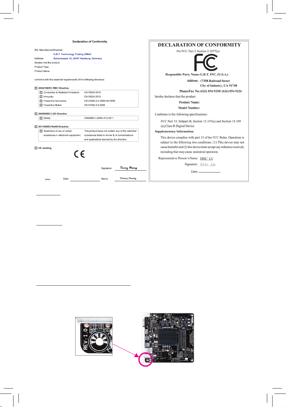
Identifying Your Motherboard Revision
The revision number on your motherboard looks like this: "REV: X.X." For example, "REV: 1.0" means the
revision of the motherboard is 1.0. Check your motherboard revision before updating motherboard BIOS,
drivers, or when looking for technical information.
Example:

Table of Contents
GA-J1800M-D2P/GA-J1900M-D2P Motherboard Layout ..............................................4
GA-J1800M-D2P/GA-J1900M-D2P Motherboard Block Diagram ..................................5
Chapter 1 Hardware Installation ..................................................................................... 6
1-1 Installation Precautions ................................................................................... 6
1-2 Product Specications ..................................................................................... 7
1-3 Installing the Memory ...................................................................................... 9
1-4 Installing an Expansion Card ........................................................................... 9
1-5 Back Panel Connectors ................................................................................... 9
1-6 Internal Connectors ........................................................................................11
Chapter 2 BIOS Setup .................................................................................................. 16
2-1 Startup Screen ............................................................................................... 16
2-2 Main ............................................................................................................... 17
2-3 Advanced ....................................................................................................... 18
2-4 Chipset ........................................................................................................... 22
2-5 Security .......................................................................................................... 23
2-6 Boot ................................................................................................................ 25
2-7 Save & Exit .................................................................................................... 26
Chapter 3 Appendix ...................................................................................................... 27
Drivers Installation .................................................................................................... 27
Regulatory Statements ............................................................................................. 28
Contact Us ................................................................................................................ 32
- 3 -
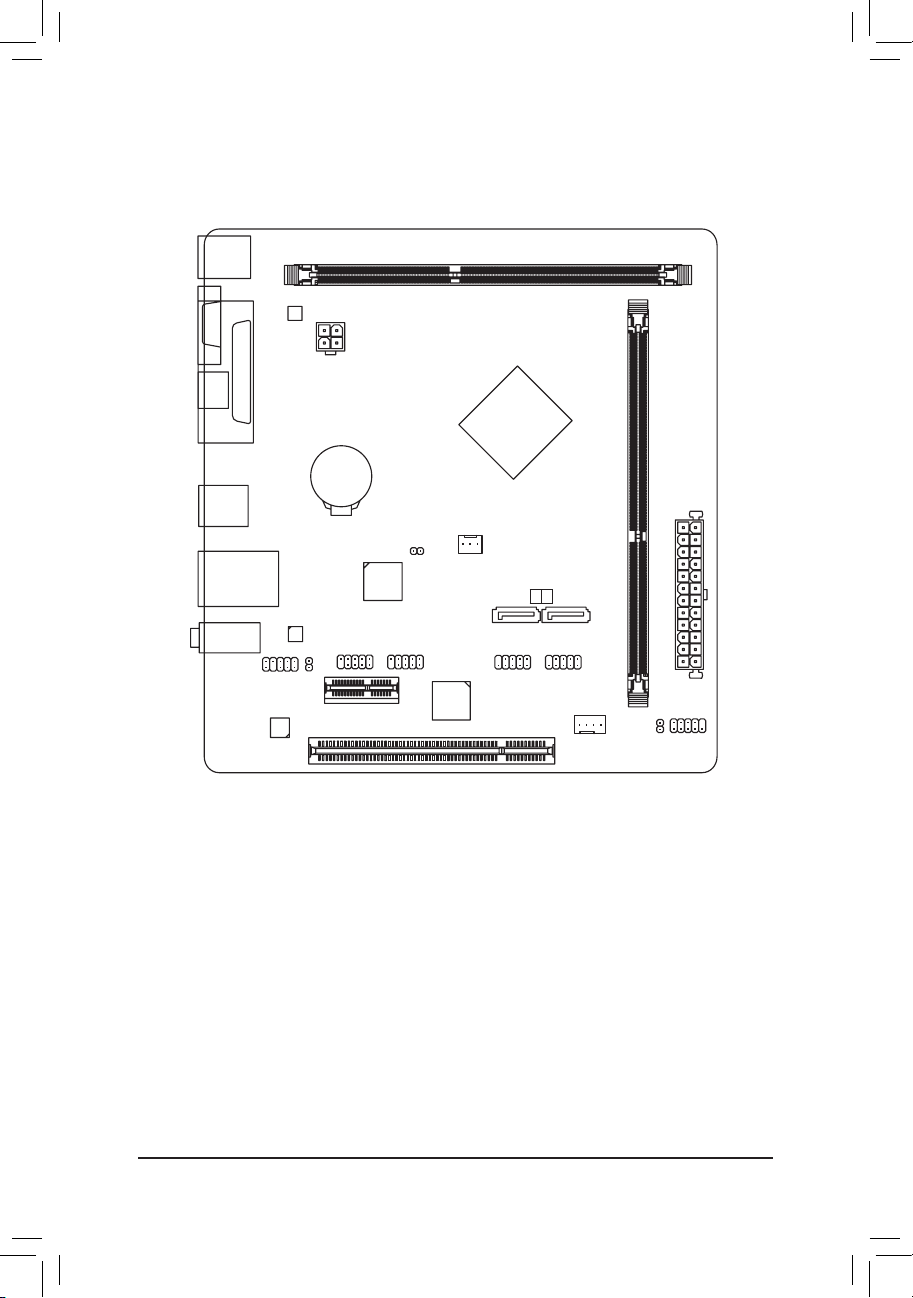
GA-J1800M-D2P/GA-J1900M-D2P Motherboard Layout
KB_MS_USB
DDR3_1
M_BIOS
VGA
ATX_12V
LPT
HDMI
BAT
USB30
GA-J1800M-D2P
GA-J1900M-D2P
Intel® J1800 SoC j
Intel® J1900 SoC k
CPU_FAN
CI
ATX
PCI
COMA
PCIEX1
iTE®
Super I/O
COMB
PCIe to PCI
Bridge
SATA 2
0 1
F_USB1 F_USB2
SYS_FAN
DDR3_2
F_PANEL
CLR_CMOS
USB_LAN
AUDIO
F_AUDIO
CODEC
Realtek®
GbE LAN
SPDIF_O
Box Contents
5 GA-J1800M-D2P or GA-J1900M-D2P motherboard
5 Motherboard driver disk 5 Two SATA cables
5 User's Manual 5 I/O Shield
The box contents above are for reference only and the actual items shall depend on the product package you obtain.
The box contents are subject to change without notice.
j Only for GA-J1800M-D2P.
k Only for GA-J1900M-D2P.
- 4 -
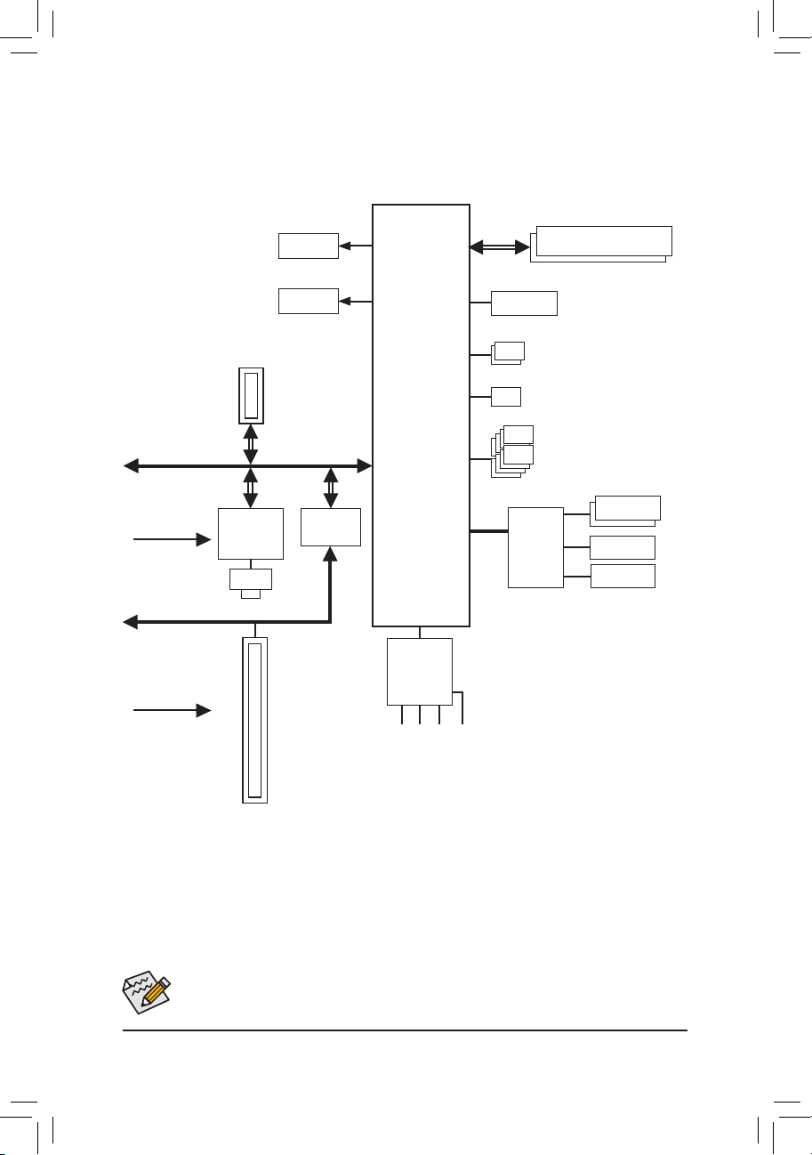
GA-J1800M-D2P/GA-J1900M-D2P Motherboard Block Diagram
DDR3/-L 1333 MHz
HDMI
Dual Channel Memory
1 PCI Express x1
PCI Express Bus
PCIe CLK
(100 MHz)
PCI Bus
PCI CLK
(33 MHz)
x1
x1
Realtek®
GbE LAN
RJ45
LAN
1 PCI
D-Sub
PCIe to PCI
Bridge
x1
Intel® J1800 SoC j
Intel® J1900 SoC k
CODEC
Speaker Out)
S/PDIF Out
MIC (Center/Subwoofer
Line In (Rear Speaker Out)
Line Out (Front Speaker Out)
LPC
Bus
BIOS
iTE®
Super I/O
2 SATA 3Gb/s
1 USB 3.0/2.0
8 USB 2.0/1.1
COM
LPT
PS/2 KB/Mouse
j Only for GA-J1800M-D2P.
k Only for GA-J1900M-D2P.
For detailed product information/limitation(s), refer to "1-2 Product Specications."
- 5 -

Chapter 1 Hardware Installation
1-1 Installation Precautions
The motherboard contains numerous delicate electronic circuits and components which can become
damaged as a result of electrostatic discharge (ESD). Prior to installation, carefully read the user's
manual and follow these procedures:
• Prior to installation, make sure the chassis is suitable for the motherboard.
• Prior to installation, do not remove or break motherboard S/N (Serial Number) sticker or
warranty sticker provided by your dealer. These stickers are required for warranty validation.
• Always remove the AC power by unplugging the power cord from the power outlet before
installing or removing the motherboard or other hardware components.
• When connecting hardware components to the internal connectors on the motherboard, make
sure they are connected tightly and securely.
• When handling the motherboard, avoid touching any metal leads or connectors.
• It is best to wear an electrostatic discharge (ESD) wrist strap when handling electronic
components such as a motherboard, CPU or memory. If you do not have an ESD wrist strap,
keep your hands dry and rst touch a metal object to eliminate static electricity.
• Prior to installing the motherboard, please have it on top of an antistatic pad or within an
electrostatic shielding container.
• Before unplugging the power supply cable from the motherboard, make sure the power supply
has been turned off.
• Before turning on the power, make sure the power supply voltage has been set according to
the local voltage standard.
• Before using the product, please verify that all cables and power connectors of your hardware
components are connected.
• To prevent damage to the motherboard, do not allow screws to come in contact with the
motherboard circuit or its components.
• Make sure there are no leftover screws or metal components placed on the motherboard or
within the computer casing.
• Do not place the computer system on an uneven surface.
• Do not place the computer system in a high-temperature environment.
• Turning on the computer power during the installation process can lead to damage to system
components as well as physical harm to the user.
• If you are uncertain about any installation steps or have a problem related to the use of the
product, please consult a certied computer technician.
- 6 -
1-2 ProductSpecications
CPU Built in with an Intel® Dual-Core Celeron® J1800 SoC (2.41 GHz) j
Built in with an Intel® Dual-Core Celeron® J1900 SoC (2.0 GHz) k
* Do not disassemble the onboard SoC and the heatsinks by yourself to avoid damage
to these components.
1 MB Cache j
2 MB Cache k
Memory 2 x DDR3 DIMM sockets supporting up to 16 GB of system memory
Onboard
Graphics
Audio Realtek® ALC887 codec
LAN Realtek® GbE LAN chip (10/100/1000 Mbit)
Expansion Slots 1 x PCI Express x1 slot
Storage Interface Integrated in the SoC:
USB Integrated in the SoC:
Internal
Connectors
* Due to a Windows 32-bit operating system limitation, when more than 4 GB of physical
memory is installed, the actual memory size displayed will be less than the size of
the physical memory installed.
Dual channel memory architecture
Support for DDR3/-L 1333 MHz memory modules
Support for non-ECC memory modules
Integrated in the SoC:
- 1 x D-Sub port, supporting a maximum resolution of 2560x1600
- 1 x HDMI port, supporting a maximum resolution of 1920x1080
High Denition Audio
2/4/5.1/7.1-channel
* To congure 7.1-channel audio, you have to use an HD front panel audio module
and enable the multi-channel audio feature through the audio driver.
Support for S/PDIF Out
1 x PCI slot
- 2 x SATA 3Gb/s connectors
- 1 x USB 3.0/2.0 port on the back panel
- 8 x USB 2.0/1.1 ports (4 ports on the back panel, 4 ports available through
the internal USB headers)
1 x 24-pin ATX main power connector
1 x 4-pin ATX 12V power connector
2 x SATA 3Gb/s connectors
1 x CPU fan header
1 x system fan header
1 x front panel header
1 x front panel audio header
1 x S/PDIF Out header
2 x USB 2.0/1.1 headers
2 x serial port headers
1 x chassis intrusion header
1 x Clear CMOS jumper
j Only for GA-J1800M-D2P.
k Only for GA-J1900M-D2P.
- 7 -
Back Panel
Connectors
1 x PS/2 keyboard/mouse port
1 x D-Sub port
1 x HDMI port
1 x parallel port
1 x USB 3.0/2.0 port
4 x USB 2.0/1.1 ports
1 x RJ-45 port
3 x audio jacks (Line In, Line Out, Mic In)
I/O Controller iTE® I/O Controller Chip
Hardware
Monitor
System voltage detection
CPU/System temperature detection
CPU/System fan speed detection
CPU/System fan speed control
* Whether the fan speed control function is supported will depend on the cooler you
install.
BIOS 1 x 64 Mbit ash
Use of licensed AMI UEFI BIOS
PnP 1.0a, DMI 2.7, WfM 2.0, SM BIOS 2.7, ACPI 5.0
Unique Features Support for Xpress Install
Support for @BIOS
Support for APP Center
* Available applications in APP Center may differ by motherboard model. Supported
functions of each application may also differ depending on motherboard
specications.
Support for ON/OFF Charge
Bundled
Software
Operating
System
Norton® Internet Security (OEM version)
Intel® Smart Connect Technology
Support for Windows 8.1/8/7
Form Factor Micro ATX Form Factor; 19.0cm x 18.0cm
* GIGABYTE reserves the right to make any changes to the product specications and product-related information without
prior notice.
* Please visit the Support & Downloads\Utility page on GIGABYTE's website to check the supported operating system(s)
for the software listed in the "Unique Features" and "Bundled Software" columns.
- 8 -
1-3 Installing the Memory
Read the following guidelines before you begin to install the memory:
• Make sure that the motherboard supports the memory. It is recommended that memory of the
same capacity, brand, speed, and chips be used.
(Go to GIGABYTE's website for the latest supported memory speeds and memory modules.)
• Always turn off the computer and unplug the power cord from the power outlet before installing the
memory to prevent hardware damage.
• Memory modules have a foolproof design. A memory module can be installed in only one direction.
If you are unable to insert the memory, switch the direction.
DualChannelMemoryConguration
This motherboard provides two DDR3 memory sockets and supports Dual Channel Technology. After the memory
is installed, the BIOS will automatically detect the specications and capacity of the memory. Enabling Dual
Channel memory mode will double the original memory bandwidth.
The two DDR3 memory sockets are divided into two channels and each channel has one memory socket as
following:
Channel A: DDR3_1
Channel B: DDR3_2
Due to SoC limitations, read the following guidelines before installing the memory in Dual Channel mode.
1. If only one DDR3 memory module is to be installed, be sure to install it in the DDR3_1 socket, and
Dual Channel mode cannot be enabled if only one memory module is installed.
2. When enabling Dual Channel mode with two memory modules, it is recommended that memory of
the same capacity, brand, speed, and chips be used for optimum performance.
1-4 Installing an Expansion Card
Read the following guidelines before you begin to install an expansion card:
• Make sure the motherboard supports the expansion card. Carefully read the manual that came
with your expansion card.
• Always turn off the computer and unplug the power cord from the power outlet before installing an
expansion card to prevent hardware damage.
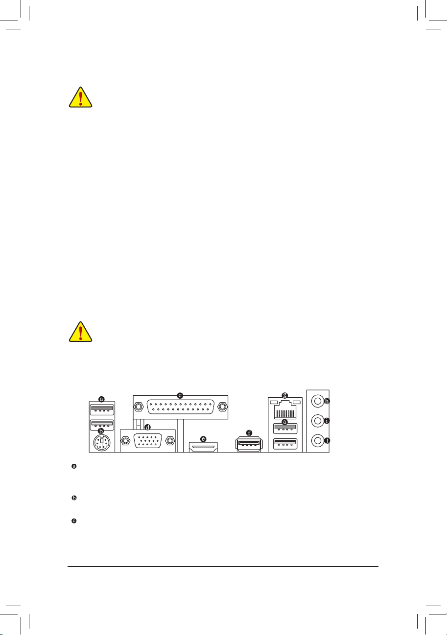
1-5 Back Panel Connectors
USB 2.0/1.1 Port
The USB port supports the USB 2.0/1.1 specication. Use this port for USB devices such as a USB
keyboard/mouse, USB printer, USB ash drive and etc.
PS/2 Keyboard/Mouse Port
Use this port to connect a PS/2 mouse or keyboard.
Parallel Port
Use the parallel port to connect devices such as a printer, scanner and etc. The parallel port is also called
a printer port.
- 9 -
D-Sub Port
The D-Sub port supports a 15-pin D-Sub connector and supports a maximum resolution of 2560x1600
(the actual resolutions supported depend on the monitor being used). Connect a monitor that supports
D-Sub connection to this port.
HDMI Port
The HDMI port is HDCP compliant and supports Dolby True HD and DTS HD
Master Audio formats. It also supports up to 192KHz/24bit 8-channel LPCM audio
output. You can use this port to connect your HDMI-supported monitor. The maximum supported resolution
is 1920x1080, but the actual resolutions supported are dependent on the monitor being used.
After installing the HDMI device, make sure to set the default sound playback device to HDMI.
DualDisplayCongurationsfortheOnboardGraphics:
Dual-display congurations are supported after you install motherboard drivers in OS, but not during the
BIOS Setup or POST process.
USB 3.0/2.0 Port
The USB 3.0 port supports the USB 3.0 specication and is compatible to the USB 2.0/1.1 specication.
Use this port for USB devices such as a USB keyboard/mouse, USB printer, USB ash drive and etc.
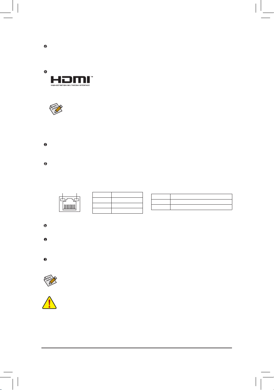
RJ-45 LAN Port
The Gigabit Ethernet LAN port provides Internet connection at up to 1 Gbps data rate. The following
describes the states of the LAN port LEDs.
Connection/
Speed LED
Activity LED
LAN Port
Connection/Speed LED:
State Description
Orange 1 Gbps data rate
Green 100 Mbps data rate
Off 10 Mbps data rate
Activity LED:
State Description
Blinking Data transmission or receiving is occurring
Off No data transmission or receiving is occurring
Line In Jack (Blue)
The line in jack. Use this audio jack for line in devices such as an optical drive, walkman, etc.
Line Out Jack (Green)
The line out jack. Use this audio jack for a headphone or 2-channel speaker. This jack can be used to
connect front speakers in a 4/5.1/7.1-channel audio conguration.
Mic In Jack (Pink)
The Mic in jack. Microphones must be connected to this jack.
To congure 7.1-channel audio, you have to use an HD front panel audio module and enable the
multi-channel audio feature through the audio driver.
• When removing the cable connected to a back panel connector, rst remove the cable from your
device and then remove it from the motherboard.
• When removing the cable, pull it straight out from the connector. Do not rock it side to side to prevent
an electrical short inside the cable connector.
- 10 -
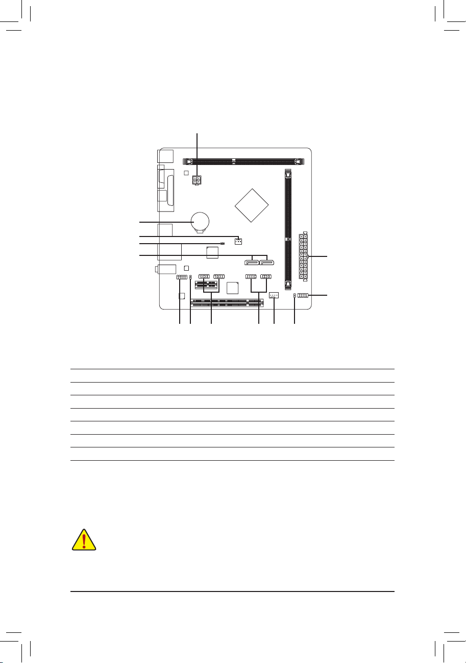
1-6 Internal Connectors
6
3
8
5
1
2
9
12 4 71310 11
1) ATX_12V
2) ATX
3) CPU_FAN
4) SYS_FAN
5) SATA2 0/1
6) BAT
8) CI
9) F_PANEL
10) F_AUDIO
11) SPDIF_O
12) F_USB1/F_USB2
13) COMA/COMB
7) CLR_CMOS
Read the following guidelines before connecting external devices:
• First make sure your devices are compliant with the connectors you wish to connect.
• Before installing the devices, be sure to turn off the devices and your computer. Unplug the power
cord from the power outlet to prevent damage to the devices.
• After installing the device and before turning on the computer, make sure the device cable has been
securely attached to the connector on the motherboard.
- 11 -

1/2) ATX_12V/ATX (2x2 12V Power Connector and 2x12 Main Power Connector)
With the use of the power connector, the power supply can supply enough stable power to all the components
on the motherboard. Before connecting the power connector, rst make sure the power supply is turned
off and all devices are properly installed. The power connector possesses a foolproof design. Connect the
power supply cable to the power connector in the correct orientation.
The 12V power connector mainly supplies power to the CPU. If the 12V power connector is not connected,
the computer will not start.
3
4
ATX_12V
12
ATX
ATX_12V:
1
2
24
131
Pin No. Denition
1 GND
2 GND
3 +12V
4 +12V
ATX:
Pin No. Denition Pin No. Denition
1 3.3V 13 3.3V
2 3.3V 14 -12V
3 GND 15 GND
4 +5V 16 PS_ON (soft On/Off)
5 GND 17 GND
6 +5V 18 GND
7 GND 19 GND
8 Power Good 20 -5V
9 5VSB (stand by +5V) 21 +5V
10 +12V 22 +5V
11 +12V (Only for 2x12-pin
ATX)
12 3.3V (Only for 2x12-pin
ATX)
23 +5V (Only for 2x12-pin ATX)
24 GND (Only for 2x12-pin
ATX)
3/4) CPU_FAN/SYS_FAN (Fan Headers)
The motherboard has a 3-pin CPU fan header (CPU_FAN) and a 4-pin system fan header (SYS_FAN).
Most fan headers possess a foolproof insertion design. When connecting a fan cable, be sure to connect it
in the correct orientation (the black connector wire is the ground wire). The speed control function requires
the use of a fan with fan speed control design. For optimum heat dissipation, it is recommended that a
system fan be installed inside the chassis.
CPU_FAN: SYS_FAN:
Pin No. Denition
1
CPU_FAN
These fan headers are not conguration jumper blocks. Do not place a jumper cap on the headers.
1 GND
2 Speed Control
3 Sense
1
SYS_FAN
- 12 -
Pin No. Denition
1 GND
2 Speed Control
3 Sense
4 VCC

5) SATA2 0/1 (SATA 3Gb/s Connectors)
The SATA connectors conform to SATA 3Gb/s standard and are compatible with SATA 1.5Gb/s standard.
Each SATA connector supports a single SATA device.
SATA 2
0 1
7
1
Pin No. Denition
1 GND
2 TXP
3 TXN
4 GND
5 RXN
6 RXP
7 GND
6) BAT (Battery)
The battery provides power to keep the values (such as BIOS congurations, date, and time information)
in the CMOS when the computer is turned off. Replace the battery when the battery voltage drops to a low
level, or the CMOS values may not be accurate or may be lost.
You may clear the CMOS values by removing the battery:
1. Turn off your computer and unplug the power cord.
2. Gently remove the battery from the battery holder and wait for one minute. (Or use a metal
object like a screwdriver to touch the positive and negative terminals of the battery holder,
making them short for 5 seconds.)
3. Replace the battery.
4. Plug in the power cord and restart your computer.
• Always turn off your computer and unplug the power cord before replacing the battery.
• Replace the battery with an equivalent one. Danger of explosion if the battery is replaced with an incorrect model.
• Contact the place of purchase or local dealer if you are not able to replace the battery by yourself or uncertain
about the battery model.
• When installing the battery, note the orientation of the positive side (+) and the negative side (-) of the battery
(the positive side should face up).
• Used batteries must be handled in accordance with local environmental regulations.
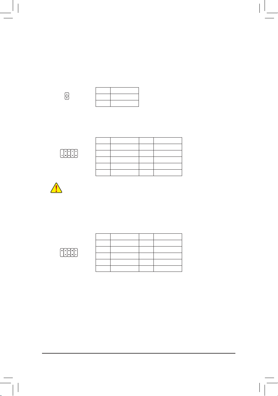
7) CLR_CMOS (Clear CMOS Jumper)
Use this jumper to clear the BIOS conguration and reset the CMOS values to factory defaults. To clear
the CMOS values, use a metal object like a screwdriver to touch the two pins for a few seconds.
Open: Normal
Short: Clear CMOS Values
• Always turn off your computer and unplug the power cord from the power outlet before clearing the CMOS values.
• After system restart, go to BIOS Setup to load factory defaults (select Load Optimized Defaults) or manually
congure the BIOS settings (refer to Chapter 2, "BIOS Setup," for BIOS congurations).
8) CI (Chassis Intrusion Header)
This motherboard provides a chassis detection feature that detects if the chassis cover has been removed.
This function requires a chassis with chassis intrusion detection design.
1
Pin No. Denition
1 Signal
2 GND
- 13 -

9) F_PANEL (Front Panel Header)
Connect the power switch, reset switch, and system status indicator on the chassis to this header according
to the pin assignments below. Note the positive and negative pins before connecting the cables.
Power LED
2
1
Hard Drive
Activity LED
PLED+
PLED-
HD-
HD+
Power Switch
PW+
PW-
RES+
RES-
Reset Switch
• PLED (Power LED, Yellow):
System Status LED
S0 On
S3/S4/S5 Off
Connects to the power status indicator on the chassis
front panel. The LED is on when the system is
operating. The LED is off when the system is in S3/
S4 sleep state or powered off (S5).
• PW (Power Switch, Red):
10
9
Connects to the power switch on the chassis front panel. You may congure the
NC
way to turn off your system using the power switch (refer to Chapter 2, "BIOS
Setup," "Chipset," for more information).
• HD (Hard Drive Activity LED, Blue):
Connects to the hard drive activity LED on the chassis front panel. The LED is
on when the hard drive is reading or writing data.
• RES (Reset Switch, Green):
Connects to the reset switch on the chassis front panel. Press the reset switch
to restart the computer if the computer freezes and fails to perform a normal
restart.
• NC (Purple): No connection.
The front panel design may differ by chassis. A front panel module mainly consists of power switch, reset switch,
power LED, hard drive activity LED and etc. When connecting your chassis front panel module to this header,
make sure the wire assignments and the pin assignments are matched correctly.
10) F_AUDIO (Front Panel Audio Header)
The front panel audio header supports Intel High Denition audio (HD) and AC'97 audio. You may connect
your chassis front panel audio module to this header. Make sure the wire assignments of the module
connector match the pin assignments of the motherboard header. Incorrect connection between the module
connector and the motherboard header will make the device unable to work or even damage it.
For HD Front Panel Audio: For AC'97 Front Panel Audio:
19
210
Pin No. Denition
1 MIC2_L
2 GND
3 MIC2_R
4 -ACZ_DET
5 LINE2_R
6 GND
7 FAUDIO_JD
8 No Pin
9 LINE2_L
10 GND
Pin No. Denition
1 MIC
2 GND
3 MIC Power
4 NC
5 Line Out (R)
6 NC
7 NC
8 No Pin
9 Line Out (L)
10 NC
• The front panel audio header supports HD audio by default.
• Audio signals will be present on both of the front and back panel audio connections simultaneously.
• Some chassis provide a front panel audio module that has separated connectors on each wire instead of a
single plug. For information about connecting the front panel audio module that has different wire assignments,
please contact the chassis manufacturer.
- 14 -
11) SPDIF_O (S/PDIF Out Header)
This header supports digital S/PDIF Out and connects a S/PDIF digital audio cable (provided by expansion
cards) for digital audio output from your motherboard to certain expansion cards like graphics cards and
sound cards. For example, some graphics cards may require you to use a S/PDIF digital audio cable for
digital audio output from your motherboard to your graphics card if you wish to connect an HDMI display
to the graphics card and have digital audio output from the HDMI display at the same time. For information
about connecting the S/PDIF digital audio cable, carefully read the manual for your expansion card.
Pin No. Denition
1 SPDIFO
1
2 GND
12) F_USB1/F_USB2 (USB 2.0/1.1 Headers)
The headers conform to USB 2.0/1.1 specication. Each USB header can provide two USB ports via an
optional USB bracket. For purchasing the optional USB bracket, please contact the local dealer.
1
9
210
• Do not plug the IEEE 1394 bracket (2x5-pin) cable into the USB header.
• Prior to installing the USB bracket, be sure to turn off your computer and unplug the power cord from the power
outlet to prevent damage to the USB bracket.
Pin No. Denition Pin No. Denition
1 Power (5V) 6 USB DY+
2 Power (5V) 7 GND
3 USB DX- 8 GND
4 USB DY- 9 No Pin
5 USB DX+ 10 NC
13) COMA/COMB (Serial Port Headers)
The COM header can provide one serial port via an optional COM port cable. For purchasing the optional
COM port cable, please contact the local dealer.
Pin No. Denition Pin No. Denition
921
10
1 NDCD- 6 NDSR-
2 NSIN 7 NRTS-
3 NSOUT 8 NCTS-
4 NDTR- 9 NRI-
5 GND 10 No Pin
- 15 -
Chapter 2 BIOS Setup
BIOS (Basic Input and Output System) records hardware parameters of the system in the CMOS on the
motherboard. Its major functions include conducting the Power-On Self-Test (POST) during system startup,
saving system parameters and loading operating system, etc. BIOS includes a BIOS Setup program that allows
the user to modify basic system conguration settings or to activate certain system features.
When the power is turned off, the battery on the motherboard supplies the necessary power to the CMOS to
keep the conguration values in the CMOS.
To access the BIOS Setup program, press the <Delete> key during the POST when the power is turned on.
To upgrade the BIOS, use the GIGABYTE @BIOS utility, which is a Windows-based utility that searches and
downloads the latest version of BIOS from the Internet and updates the BIOS.
• Because BIOS ashing is potentially risky, if you do not encounter problems using the current version of BIOS, it
is recommended that you not ash the BIOS. To ash the BIOS, do it with caution. Inadequate BIOS ashing may
result in system malfunction.
• It is recommended that you not alter the default settings (unless you need to) to prevent system instability or other
unexpected results. Inadequately altering the settings may result in system's failure to boot. If this occurs, try to clear
the CMOS values and reset the board to default values. (Refer to the "Restore Defaults" section in this chapter or
introductions of the battery/clear CMOS jumper in Chapter 1 for how to clear the CMOS values.)
2-1 Startup Screen
The following startup Logo screen will appear when the computer boots.
- 16 -
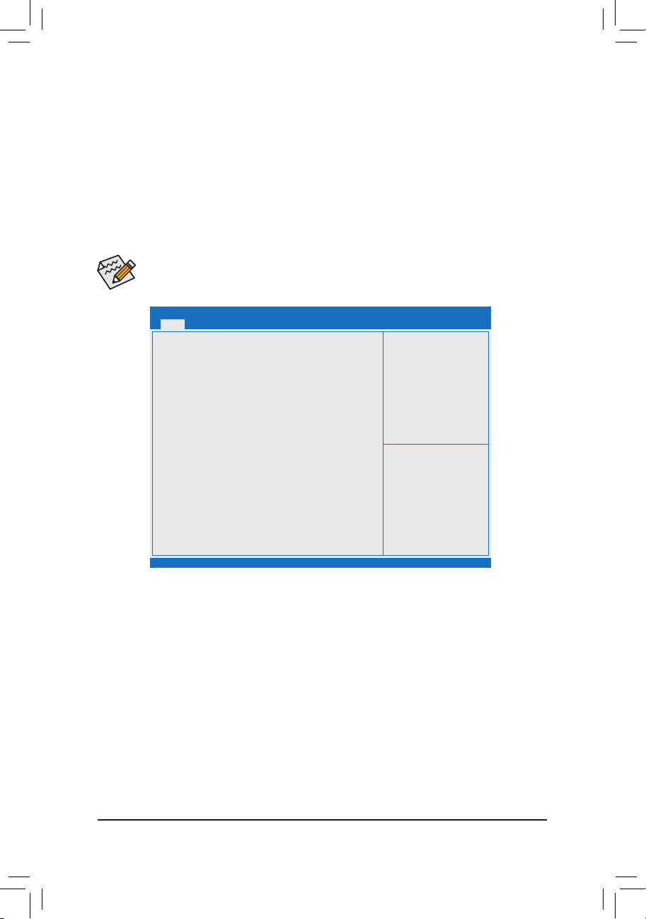
2-2 Main
Once you enter the BIOS Setup program, the Main Menu (as shown below) appears on the screen. Use
arrow keys to move among the items and press <Enter> to accept or enter a sub-menu.
Main Menu Help
The on-screen description of a highlighted setup option is displayed on the bottom line of the Main Menu.
Submenu Help
While in a submenu, press <F1> to display a help screen (General Help) of function keys available for the menu.
Press <Esc> to exit the help screen. Help for each item is in the Item Help block on the right side of the submenu.
(SampleBIOSVersion:GA-J1800M-D2PE13)
• When the system is not stable as usual, select the Restore Defaults item to set your system to its
defaults.
• The BIOS Setup menus described in this chapter are for reference only and may differ by BIOS version.
Main
BIOS Information
BIOS ID 8A05AG0A
Project Nate J1800M-D2P
BIOS Version E13
Build Date and Time 07/04/2014 15:01:11
Memory Information
Total Memory 1024 MB (LPDDR3)
System Language [English]
System Date [Fri 07/25/2014]
System Time [12:25:23 AM]
Access Level
Aptio Setup Utility - Copyright (C) 2013 American Megatrends, Inc.
Aptio Setup Utility - Copyright (C) 2013 American Megatrends, Inc.
BootAdvanced Save & ExitSecurityChipset
gf: Select Screen
hi: Select Item
[ENTER]-Select
+/-: Change Opt.
F1: General Help
F2: Previous Values
F3: Optimized Defaults
F4: Save & Exit
ESC: Exit
This section provides information on your motherboard model and BIOS version. You can also select the default
language used by the BIOS and manually set the system time.
• System Language
Selects the default language used by the BIOS.
• System Date
Sets the system date. The date format is week (read-only), month, date, and year. Use <Tab> to switch
between the Month, Date, and Year elds and use the <+> or <-> key to set the desired value.
• System Time
Sets the system time. The time format is hour, minute, and second. For example, 1 p.m. is 13:0:0. Use
<Tab> to switch between the Hour, Minute, and Second elds and use the <+> or <-> key to set the desired
value.
• Access Level
Displays the current access level depending on the type of password protection used. (If no password is
set, the default will display as Administrator.) The Administrator level allows you to make changes to all
BIOS settings; the User level only allows you to make changes to certain BIOS settings but not all.
- 17 -
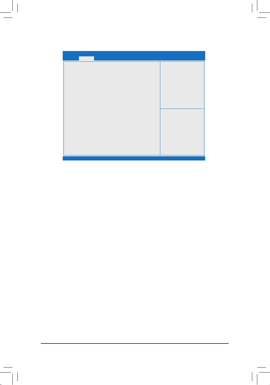
2-3 Advanced
Main
Resume by Alarm [Disabled]
Wale up day 0
Wake up hour 0
Wake up minute 0
Wake up second 0
Power Loading [Auto]
DDR Voltage Control [Auto]
` Hardware Monitor
` Intel(R) Smart Connect Technology
` SIO Misc Functions
` CPU Conguration
` PPM Conguration
` Thermal Conguration
` IDE Conguration
` Network Stack Conguration
` CSM Conguration
` USB Conguration
` Realtek PCIe GBE Family Controller (MAC:74:D4:35:8C:3E:68)
` SIO Conguration
& Resume by Alarm
Determines whether to power on the system at a desired time. (Default: Disabled)
If enabled, set the date and time as following:
Wake up day: Turn on the system at a specic time on each day or on a specic day in a month.
Wake up hour/minute/second: Set the time at which the system will be powered on automatically.
Note: When using this function, avoid inadequate shutdown from the operating system or removal of the
AC power, or the settings may not be effective.
& Power Loading
Enables or disables dummy load. When the power supply is at low load, a self-protection will activate causing
it to shutdown or fail. If this occurs, please set to Enabled. Auto lets the BIOS automatically congure this
setting. (Default: Auto)
& DDR Voltage Control
Allows you to set the memory voltage. Options are: Normal, 1.50V, 1.60V, Auto. Auto lets the BIOS
automatically congure this setting. (Default: Auto)
Aptio Setup Utility - Copyright (C) 2013 American Megatrends, Inc.
Aptio Setup Utility - Copyright (C) 2013 American Megatrends, Inc.
Boot Save & ExitSecurityChipsetAdvanced
gf: Select Screen
hi: Select Item
Enter: Select
+/-: Change Opt.
F1: General Help
F2: Previous Values
F3: Optimized Defaults
F4: Save & Exit
ESC: Exit
` Hardware Monitor
& CPU Temperature (DTS)/System Temperature
Displays current CPU/system temperature.
& CPU/System Fan Speed
Displays current CPU/system fan speeds.
& Vcore/VCC3/+12V/VCC/CPU_VAXG/3VDUAL/DDR1_35VIO
Displays the current system voltages.
` Intel(R) Smart Connect Technology
& ISCT Support
Enables or disables Intel® Smart Connect Technology. (Default: Disabled)
- 18 -

` SIO Misc Functions
& ErP
Determines whether to let the system consume least power in S5 (shutdown) state. (Default: Disabled)
Note: When this item is set to Enabled, the following functions will become unavailable: Resume by Alarm,
PME event wake up, power on by mouse, power on by keyboard, and wake on LAN.
& AC BACK
Determines the state of the system after the return of power from an AC power loss.
Memory The system returns to its last known awake state upon the return of the AC power.
Always On The system is turned on upon the return of the AC power.
Always Off The system stays off upon the return of the AC power. (Default)
& Case Open
Displays the detection status of the chassis intrusion detection device attached to the motherboard CI
header. If the system chassis cover is removed, this eld will show "Open", otherwise it will show "Close."
To clear the chassis intrusion status record, set Reset Case Open Status to Enabled, save the settings
to the CMOS, and then restart your system.
& Reset Case Open Status
Disabled Keeps or clears the record of previous chassis intrusion status. (Default)
Enabled Clears the record of previous chassis intrusion status and the Case Open eld will
show "No" at next boot.
& Case intrusion Prompt
Allows the system to display a chassis intrusion notication when system boots. (Default: Disabled)
` CPUConguration
` Socket 0 CPU Information
This section provides information on your CPU, frequency, and cache memory.
& Limit CPUID Maximum
Allows you to determine whether to limit CPUID maximum value. Set this item to Disabled for Windows XP
operating system; set this item to Enabled for legacy operating system such as Windows NT4.0. (Default:
Disabled)
& Execute Disable Bit
Enables or disables Intel® Execute Disable Bit function. This function may enhance protection for the
computer, reducing exposure to viruses and malicious buffer overow attacks when working with its
supporting software and system. (Default: Enabled)
& Hardware Prefetcher
Enables or disables L2 Cache Hardware Prefetcher. (Default: Enabled)
& Adjacent Cache Line Prefetch
Enables or disables L2 prefetching of adjacent cache lines. (Default: Enabled)
& Intel Virtualization Technology
Enables or disables Intel® Virtualization Technology. Virtualization enhanced by Intel® Virtualization
Technology will allow a platform to run multiple operating systems and applications in independent partitions.
With virtualization, one computer system can function as multiple virtual systems. (Default: Enabled)
& Power Technology
Allows you to congure Intel® power management features. (Default: Energy Efcient)
- 19 -

` PPMConguration
& CPU C state Report
Enables or disables support for CPU's power-saving functions. (Default: Enabled)
& Enhanced C state
Enables or disables Intel® CPU Enhanced Halt (C1E) function, a CPU power-saving function in system
halt state. When enabled, the CPU core frequency and voltage will be reduced during system halt state
to decrease power consumption. This item is congurable only when CPU C state Report is enabled.
(Default: Enabled)
& Max CPU C-state
Allows you to determine the maximum C state that the CPU will support. Options include: C6, C1 (default).
This item is congurable only when CPU C state Report is enabled.
` ThermalConguration
& DTS
Enables or disables the CPU overheating protection function. (Default: Disabled)
& Critical Trip Point
Allows you to set the CPU temperature threshold. If the CPU temperature reaches this value, the operating
system will shut down the system. This item is congurable only when DTS is enabled. (Default: 100 C)
& Passive Trip Point
Allows you to set the CPU temperature threshold. If the CPU temperature reaches this value, the CPU frequency
will be automatically reduced. This item is congurable only when DTS is enabled. (Default: 85 C)
` IDEConguration
& Serial-ATA (SATA)
Enables or disables the integrated SATA controllers. (Default: Enabled)
& SATA Mode
Allows you to decide whether to congure the SATA controller integrated in the Chipset to AHCI mode. This
item is congurable only when Serial-ATA(SATA) is set to Enabled.
IDE Mode Disables RAID for the SATA controllers and congures the SATA controllers to IDE
mode.
AHCI Mode Congures the SATA controllers to AHCI mode. Advanced Host Controller Interface
(AHCI) is an interface specication that allows the storage driver to enable advanced
Serial ATA features such as Native Command Queuing and hot plug. (Default)
& Serial-ATA Port 0/Serial-ATA Port 1
Enables or disables each SATA port. This item is congurable only when Serial-ATA(SATA) is set to
Enabled. (Default: Enabled)
& SATA Port0/SATA Port1 HotPlug
Enables or disable the hot plug capability for each SATA port. This item is congurable only when Serial-
ATA( SATA) is set to Enabled. (Default: Disabled)
The area below displays the current status of each SATA port.
` NetworkStackConguration
& Network stack
Disables or enables booting from the network to install a GPT format OS, such as installing the OS from
the Windows Deployment Services server. (Default: Disabled)
& Ipv4 PXE Support
Enables or disables IPv4 PXE Support. This item is congurable only when Network stack is enabled.
- 20 -

& Ipv6 PXE Support
Enables or disables IPv6 PXE Support. This item is congurable only when Network stack is enabled.
` CSMConguration
& CSM Support
Enables or disables UEFI CSM (Compatibility Support Module) to support a legacy PC boot process.
Enabled Enables UEFI CSM. (Default)
Disabled Disables UEFI CSM and supports UEFI BIOS boot process only.
& Bootoptionlter
Allows you to select which type of operating system to boot.
UEFI and Legacy Allows booting from operating systems that support legacy option ROM or UEFI
option ROM. (Default)
Legacy Only Allows booting from operating systems that only support legacy Option ROM.
UEFI Only Allows booting from operating systems that only support UEFI Option ROM.
This item is congurable only when CSM Support is set to Enabled.
& Network
Allows you to select whether to enable the UEFI or legacy option ROM for the LAN controller.
Do not launch Disables option ROM. (Default)
UEFI only Enables UEFI option ROM only.
Legacy only Enables legacy option ROM only.
Legacy First Enables legacy option ROM rst.
UEFI First Enables UEFI option ROM rst.
This item is congurable only when CSM Support is set to Enabled.
& Storage
Allows you to select whether to enable the UEFI or legacy option ROM for the storage device controller.
Do not launch Disables option ROM.
UEFI only Enables UEFI option ROM only.
Legacy only Enables legacy option ROM only. (Default)
Legacy First Enables legacy option ROM rst.
UEFI First Enables UEFI option ROM rst.
This item is congurable only when CSM Support is set to Enabled.
& Video
Allows you to select whether to enable the UEFI or legacy option ROM for the graphics controller.
Do not launch Disables option ROM.
UEFI only Enables UEFI option ROM only.
Legacy only Enables legacy option ROM only. (Default)
Legacy First Enables legacy option ROM rst.
UEFI First Enables UEFI option ROM rst.
This item is congurable only when CSM Support is set to Enabled.
& Other PCI devices
Allows you to select whether to enable the UEFI or Legacy option ROM for the PCI device controller other
than the LAN, storage device, and graphics controllers.
UEFI First Enables UEFI option ROM rst. (Default)
Legacy only Enables legacy option ROM only.
This item is congurable only when CSM Support is set to Enabled.
- 21 -

` USBConguration
& Legacy USB Support
Allows USB keyboard/mouse to be used in MS-DOS. (Default: Enabled)
& USB3.0 Support
Enables or disables the USB 3.0 controller. (Default: Enabled)
& XHCI Hand-off
Determines whether to enable XHCI Hand-off feature for an operating system without XHCI Hand-off
support. (Default: Enabled)
& EHCI Hand-off
Determines whether to enable EHCI Hand-off feature for an operating system without EHCI Hand-off
support. (Default: Disabled)
& USB Mass Storage Driver Support
Enables or disables support for USB storage devices. (Default: Enabled)
& Mass Storage Devices
Displays a list of connected USB mass storage devices. This item appears only when a USB storage device
is installed.
` Realtek PCIe GBE Family Controller
This sub-menu provides information on LAN conguration and related conguration options.
` SIOConguration
This section provides information on the super I/O chip and allows you to congure the serial port and
parallel port.
2-4 Chipset
Main
Realtek LAN Controller [Enabled]
` North Bridge
` South Bridge
Aptio Setup Utility - Copyright (C) 2013 American Megatrends, Inc.
Boot Save & ExitSecurityChipsetAdvanced
gf: Select Screen
hi: Select Item
[ENTER]-Select
+/-: Change Opt.
F1: General Help
F2: Previous Values
F3: Optimized Defaults
F4: Save & Exit
ESC: Exit
Aptio Setup Utility - Copyright (C) 2013 American Megatrends, Inc.
& Realtek LAN Controller
Enables or disables the onboard LAN function. (Default: Enabled)
If you wish to install a 3rd party add-in network card instead of using the onboard LAN, set this item to
Disabled.
- 22 -

` North Bridge
This section provides information on the installed memory size and memory/onboard graphics-related
conguration options.
` IntelIGDConguration
This section provides onboard graphics-related conguration options.
& MAX TOLUD
Allows you to congure the maximum TOLUD value. (Default: Dynamic)
` South Bridge
This section provides information on the installed memory size and memory/onboard graphics-related
conguration options.
` USBConguration
This section provides you with conguration options for the USB controller, such as enabling/disabling a
specic USB port and support for certain features.
` PCIExpressConguration
This section provides you with conguration options for the PCI Express bus, such as enabling/disabling
a specic PCI Express channel and speed conguration.
& Audio Controller
Enables or disables the onboard audio function. (Default: Enabled)
If you wish to install a 3rd party add-in audio card instead of using the onboard audio, set this item to
Disabled.
& High Precision Timer
Enables or disables High Precision Event Timer (HPET) in the operating system. (Default: Enabled)
& Soft-Off by PWR-BTTN
Congures the way to turn off the computer in MS-DOS mode using the power button.
Instant-Off Press the power button and then the system will be turned off instantly. (Default)
Delay 4 Sec. Press and hold the power button for 4 seconds to turn off the system. If the power
button is pressed for less than 4 seconds, the system will enter suspend mode.
2-5 Security
Main
Password Description
If ONLY the Administrator's password is set,
then this only limits access to Setup and is
only asked for when entering Setup.
If ONLY the Administrator's password is set,
is a power on password and must be entered to
boot or enter Setup. In Setup the User will
have Administrator rights.
The password length must be
in the following range:
Minimum length 3
Maximum length 20
Administrator Password
User Password
HDD Security Conguration:
P1: Kingston SSD
` Secure Boot menu
Aptio Setup Utility - Copyright (C) 2013 American Megatrends, Inc.
Aptio Setup Utility - Copyright (C) 2013 American Megatrends, Inc.
Boot Save & ExitSecurityChipsetAdvanced
gf: Select Screen
hi: Select Item
[ENTER]-Select
+/-: Change Opt.
F1: General Help
F2: Previous Values
F3: Optimized Defaults
F4: Save & Exit
ESC: Exit
- 23 -

& Administrator Password
Allows you to congure an administrator password. Press <Enter> on this item, type the password, and
then press <Enter>. You will be requested to conrm the password. Type the password again and press
<Enter>. You must enter the administrator password (or user password) at system startup and when entering
BIOS Setup. Differing from the user password, the administrator password allows you to make changes to
all BIOS settings.
& User Password
Allows you to congure a user password. Press <Enter> on this item, type the password, and then press
<Enter>. You will be requested to conrm the password. Type the password again and press <Enter>.
You must enter the administrator password (or user password) at system startup and when entering BIOS
Setup. However, the user password only allows you to make changes to certain BIOS settings but not all.
To cancel the password, press <Enter> on the password item and when requested for the password, enter
the correct one rst. When prompted for a new password, press <Enter> without entering any password.
Press <Enter> again when prompted to conrm.
& HDDSecurityConguration
Displays a list of connected hard drives and allows you to set a password for a specic hard drive. This
item appears only when a hard drive is installed.
` Secure Boot menu
& System Mode
Displays the current system mode.
& Secure Boot
Displays the current secure boot state.
& Secure Boot
Enables or disables the secure boot function. Secure Boot requires all the applications that are running
during the booting process to be pre-signed with valid digital certicates. This way, the system knows all
the les being loaded before Windows 8 loads and gets to the login screen have not been tampered with.
(Default: Disabled)
& Secure Boot Mode
Allows you to congure the secure boot mode. (Default: Custom)
` Key Management
This section provides you with conguration options for secure boot key management.
- 24 -

2-6 Boot
Main
Boot Conguration
Setup Prompt Timeout 6
Bootup NumLock State
Full Screen LOGO Show [Enabled]
Quick Boot [Disabled]
Boot Option Priorities
Boot Option #1 [UEFI: USB 2.0 USB F ...]
Boot Option #2 [UEFI: USB 2.0 F ...]
CD/DVD ROM Drive BBS Priorities
Hard Drive BBS Priorities
& Setup Prompt Timeout
Allows you to congure the number of seconds to stay in BIOS setup prompt screen. (Default: 6)
& Bootup NumLock State
Enables or disables Numlock feature on the numeric keypad of the keyboard after the POST. (Default: On)
& Full Screen LOGO Show
Allows you to determine whether to display the GIGABYTE Logo at system startup. Disabled skips the
GIGABYTE Logo when the system starts up. (Default: Enabled)
& Fast Boot
Enables or disables Fast Boot to shorten the OS boot process. (Default: Disabled)
& VGA Support
Allows you to select which type of operating system to boot.
Auto Enables legacy option ROM only.
EFI Driver Enables EFI option ROM. (Default)
This item is congurable only when Fast Boot is set to Enabled.
& USB Support
Disabled All USB devices are disabled before the OS boot process completes.
Full Initial All USB devices are functional in the operating system and during the POST.
Partial Initial Part of the USB devices are disabled before the OS boot process completes. (Default)
This item is congurable only when Fast Boot is set to Enabled.
& PS2 Devices Support
Disabled All PS/2 devices are disabled before the OS boot process completes.
Enabled All PS/2 devices are functional in the operating system and during the POST. (Default)
This item is congurable only when Fast Boot is set to Enabled.
& NetWork Stack Driver Support
Disabled Disables booting from the network. (Default)
Enabled Enables booting from the network.
This item is congurable only when Fast Boot is set to Enabled.
Aptio Setup Utility - Copyright (C) 2013 American Megatrends, Inc.
Aptio Setup Utility - Copyright (C) 2013 American Megatrends, Inc.
Boot Save & ExitSecurityChipsetAdvanced
gf: Select Screen
hi: Select Item
[ENTER]-Select
+/-: Change Opt.
F1: General Help
F2: Previous Values
F3: Optimized Defaults
F4: Save & Exit
ESC: Exit
- 25 -

& Boot Option #1/2/3
Species the overall boot order from the available devices. For example, you can set hard drive as the
rst priority (Boot Option #1) and DVD ROM drive as the second priority (Boot Option #2). The list only
displays the device with the highest priority for a specic type. For example, only hard drive dened as the
rst priority on the Hard Drive BBS Priorities submenu will be presented here.
Removable storage devices that support GPT format will be prexed with "UEFI:" string on the boot device
list. To boot from an operating system that supports GPT partitioning, select the device prexed with "UEFI:"
string.
Or if you want to install an operating system that supports GPT partitioning such as Windows 7 64-bit, select
the optical drive that contains the Windows 7 64-bit installation disk and is prexed with "UEFI:" string.
& Hard Drive/CD/DVD ROM Drive/Floppy Drive/Network Device BBS Priorities
Species the boot order for a specic device type, such as hard drives, optical drives, oppy disk drives,
and devices that support Boot from LAN function, etc. Press <Enter> on this item to enter the submenu that
presents the devices of the same type that are connected. This item is present only if at least one device
for this type is installed.
2-7 Save & Exit
Main
Save Changes and Reset
Save Changes and Reset
Restore Defaults
Save as User Defaults
Restore User Defaults
Boot Override
UEFI: USB 2.0 USB Flash Drive 0.00
UEFI: Built-in EFI Shell
Launch EFI Shell from lesystem device
Aptio Setup Utility - Copyright (C) 2013 American Megatrends, Inc.
Boot Save & ExitSecurityChipsetAdvanced
gf: Select Screen
hi: Select Item
[ENTER]-Select
+/-: Change Opt.
F1: General Help
F2: Previous Values
F3: Optimized Defaults
F4: Save & Exit
ESC: Exit
Aptio Setup Utility - Copyright (C) 2013 American Megatrends, Inc.
& Save Changes and Reset
Press <Enter> on this item and select Yes. This saves the changes to the CMOS and exits the BIOS Setup
program. Select No or press <Esc> to return to the BIOS Setup Main Menu.
& Discard Changes and Reset
Press <Enter> on this item and select Yes. This exits the BIOS Setup without saving the changes made
in BIOS Setup to the CMOS. Select No or press <Esc> to return to the BIOS Setup Main Menu.
& Restore Defaults
Press <Enter> on this item and select Ye s to load the BIOS factory default settings. The BIOS defaults
settings help the system to operate in optimum state. Always load the Optimized defaults after updating
the BIOS or after clearing the CMOS values.
& Save as User Defaults
Save to current BIOS settings as user-dened default settings.
- 26 -
& Restore User Defaults
Load the user-dene default settings for all BIOS options.
& Boot Override
Allows you to select a device to boot immediately. Press <Enter> on the device you select and select Yes
to conrm. Your system will restart automatically and boot from that device.
& LaunchEFIShellfromlesystemdevice
Allows you to launch the EFI Shell application (shell.e) from one of the available lesystem devices. Press
<Enter> on this option and the system will restart to the EFI Shell screen automatically.
Chapter 3 Appendix
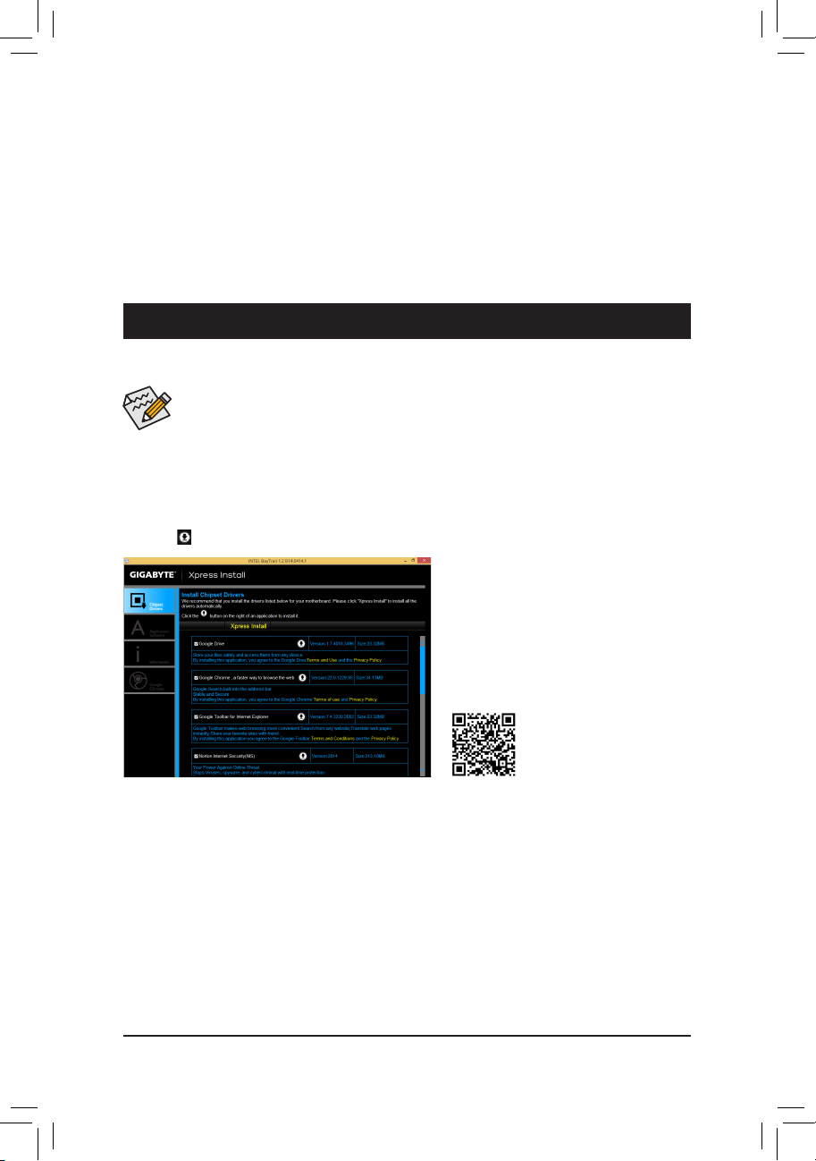
Drivers Installation
• Before installing the drivers, rst install the operating system. (The following instructions use Windows
8.1 as the example operating system.)
• After installing the operating system, insert the motherboard driver disk into your optical drive. Click
on the message "Tap to choose what happens with this disc" on the top-right corner of the screen
and select "Run Run.exe." (Or go to My Computer, double-click the optical drive and execute the
Run.exe program.)
"Xpress Install" will automatically scan your system and then list all of the drivers that are recommended to
install. You can click the Xpress Install button and "Xpress Install" will install all of the selected drivers. Or click
the arrow icon to individually install the drivers you need.
- 27 -
For more software information,
please visit GIGABYTE's website.

Regulatory Statements
Regulatory Notices
This document must not be copied without our written permission, and the contents there of must not be imparted
to a third party nor be used for any unauthorized purpose.
Contravention will be prosecuted. We believe that the information contained herein was accurate in all respects
at the time of printing. GIGABYTE cannot, however, assume any responsibility for errors or omissions in this text.
Also note that the information in this document is subject to change without notice and should not be construed
as a commitment by GIGABYTE.
Our Commitment to Preserving the Environment
In addition to high-efciency performance, all GIGABYTE motherboards fulll European Union regulations
for RoHS (Restriction of Certain Hazardous Substances in Electrical and Electronic Equipment) and WEEE
(Waste Electrical and Electronic Equipment) environmental directives, as well as most major worldwide safety
requirements. To prevent releases of harmful substances into the environment and to maximize the use of our
natural resources, GIGABYTE provides the following information on how you can responsibly recycle or reuse
most of the materials in your "end of life" product.
Restriction of Hazardous Substances (RoHS) Directive Statement
GIGABYTE products have not intended to add and safe from hazardous substances (Cd, Pb, Hg, Cr+6, PBDE
and PBB). The parts and components have been carefully selected to meet RoHS requirement. Moreover, we at
GIGABYTE are continuing our efforts to develop products that do not use internationally banned toxic chemicals.
Waste Electrical & Electronic Equipment (WEEE) Directive Statement
GIGABYTE will fulll the national laws as interpreted from the 2002/96/EC WEEE (Waste Electrical and Electronic
Equipment) directive. The WEEE Directive species the treatment, collection, recycling and disposal of electric
and electronic devices and their components. Under the Directive, used equipment must be marked, collected
separately, and disposed of properly.
WEEE Symbol Statement
The symbol shown below is on the product or on its packaging, which indicates that this product
must not be disposed of with other waste. Instead, the device should be taken to the waste collection
centers for activation of the treatment, collection, recycling and disposal procedure. The separate
collection and recycling of your waste equipment at the time of disposal will help to conserve
natural resources and ensure that it is recycled in a manner that protects human health and the environment.
For more information about where you can drop off your waste equipment for recycling, please contact your
local government ofce, your household waste disposal service or where you purchased the product for details
of environmentally safe recycling.
When your electrical or electronic equipment is no longer useful to you, "take it back" to your local or regional
waste collection administration for recycling.
If you need further assistance in recycling, reusing in your "end of life" product, you may contact us at the
Customer Care number listed in your product's user's manual and we will be glad to help you with your effort.
Finally, we suggest that you practice other environmentally friendly actions by understanding and using the
energy-saving features of this product (where applicable), recycling the inner and outer packaging (including
shipping containers) this product was delivered in, and by disposing of or recycling used batteries properly.
With your help, we can reduce the amount of natural resources needed to produce electrical and electronic
equipment, minimize the use of landlls for the disposal of "end of life" products, and generally improve our
quality of life by ensuring that potentially hazardous substances are not released into the environment and are
disposed of properly.
- 28 -

FCC Notice (U.S.A. Only)
This equipment has been tested and found to comply with the limits for a Class B digital device, pursuant to Part
15 of the FCC Rules. These limits are designed to provide reasonable protection against harmful interference
in a residential installation. This equipment generates, uses, and can radiate radio frequency energy and, if not
installed and used in accordance with the instructions, may cause harmful interference to radio communications.
However, there is no guarantee that interference will not occur in a particular installation. If this equipment does
cause harmful interference to radio or television reception, which can be determined by turning the equipment
off and on, the user is encouraged to try to correct the interference by one or more of the following measures:
Reorient or relocate the receiving antenna.
Increase the separation between the equipment and receiver.
Connect the equipment into an outlet on a circuit different from that to which the receiver is connected.
Consult a dealer or experienced TV/radio technician for help.
Canada, Industry Canada (IC) Notices / Canada, avis d'Industry Canada (IC)
This Class B digital apparatus complies with Canadian ICES-003 and RSS-210.
Operation is subject to the following two conditions: (1) this device may not cause interference, and (2) this
device must accept any interference, including interference that may cause undesired operation of the device.
Cet appareil numérique de classe B est conforme aux normes canadiennes ICES-003 et RSS-210.
Son fonctionnement est soumis aux deux conditions suivantes : (1) cet appareil ne doit pas causer d'interférence
et (2) cet appareil doit accepter toute interférence, notamment les interférences qui peuvent affecter son
fonctionnement.
- 29 -

- 30 -

- 31 -
Contact Us
GIGA-BYTE TECHNOLOGY CO., LTD.
Address: No.6, Bao Chiang Road, Hsin-Tien Dist., New Taipei City 231,Taiwan
TEL: +886-2-8912-400 0, FAX: +886-2- 8912-40 05
Tech. and Non-Tech. Support (Sales/Marketing) : http://ggts.gigaby te.com.tw
WEB address (English): http://w ww.gigabyte.com
WEB address (Chinese): http://w ww.gigabyte.tw
You may go to the GIGABYTE website, select your language in the language list on the top right corner of the website.
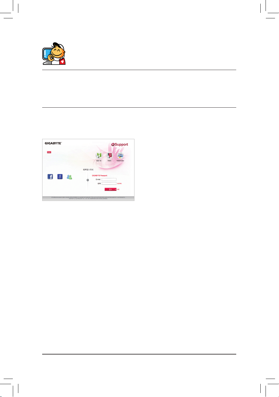
• GIGABYTE eSupport
To submit a technical or non-technical (Sales/
Marketing) question, please link to:
http://esupport.gigabyte.com
- 32 -
 Loading...