How it Works
Log In / Sign Up
Buy Points
How it Works
FAQ
Contact Us
Questions and Suggestions
Users
Gigabyte
Loading...
G
GA-F2A88XM-DS2
2
GA-F2A88XM-HD3
3
GA-F2A88XN-WIFI
2
GA-G1975X
5
GA-G1975X-C
5
GA-G31M-ES2C
18
GA-G31M-ES2L
24
GA-G31MF-S2
3
GA-G31M-S2C
4
GA-G31M-S2L
6
GA-G31MX-S2
3
GA-G31-S3G
2
GA-G31-S3L
2
GA-G33-DS3R
4
GA-G33M-DS2R
4
GA-G33M-S2
4
GA-G33M-S2H
4
GA-G33M-S2L
3
GA-G41M-COMBO
19
GA-G41M-ES2H
9
GA-G41M-ES2L
17
GA-G41MT-D3
18
GA-G41MT-D3P
14
GA-G41MT-D3PT
2
GA-G41MT-D3V
11
GA-G41MT-ES2H
15
GA-G41MT-ES2L
17
GA-G41MT-S2
22
GA-G41MT-S2P
17
GA-G41MT-S2PT
5
GA-G41MT-USB3
9
GA-GC220
GA-GC220 (rev. 1.0)
GA-GC230D
GA-GC330UD (rev. 1.0)
GA-GF2000
GA-GF2560
GA-H110-D3
GA-H110-D3A
GA-H110M-A
GA-H110M-DS2
GA-H110M-H
5
GA-H110M-S2
2
GA-H110M-S2 DDR3
GA-H110M-S2H
2
GA-H110M-S2HP
GA-H110M-S2PH DDR3
GA-H110M-S2PV
2
GA-H110M-S2V
2
GA-H110N
2
GA-H110TN
GA-H170-D3H
3
GA-H170-D3HP
5
GA-H170TN
GA-H270-Gaming 3
GA-H270N-WIFI
GA-H310N-R2
GA-H310TN
GA-H310TN-R2
2
GA-H55M-D2H
14
GA-H55M-D2H (rev. 1.4)
GA-H55M-S2
16
GA-H55M-S2H
16
GA-H55M-S2H (rev. 1.1)
GA-H55M-S2 (rev. 1.3)
GA-H55M-S2V
6
GA-H55M-S2V (rev. 1.4)
GA-H55M-UD2H
20
GA-H55M-US2H
GA-H55M-USB3
13
GA-H55M-USB3 (rev. 1.0)
GA-H55M-USB3 (rev. 2.0)
GA-H55N-USB3
12
GA-H55N-USB3 (rev. 1.0)
GA-H55-UD3H
13
GA-H55-UD3H (rev. 1.0)
GA-H55-UD3H (rev. 1.3)
GA-H55-USB3
7
GA-H57M-USB3
16
GA-H57M-USB3 (rev. 1.0)
GA-H57M-USB3 (rev. 2.0)
GA-H61M-D1
2
GA-H61M-D2-B3
16
GA-H61M-D2-B3 (rev. 1.0)
GA-H61M-D2H
3
GA-H61M-D2H-USB3
3
GA-H61M-D2P-B3
9
GA-H61M-DS2
16
GA-H61M-DS2 DVI
5
GA-H61M-DS2H
6
GA-H61M-DS2 HDMI
3
GA-H61M-DS2V
4
GA-H61M-HD2
5
GA-H61M-S
2
GA-H61M-S1
5
GA-H61M-S2-B3
4
GA-H61M-S2H
4
GA-H61M-S2P
5
GA-H61M-S2P-B3
4
GA-H61-S3
3
Loading...
Loading...
Nothing found
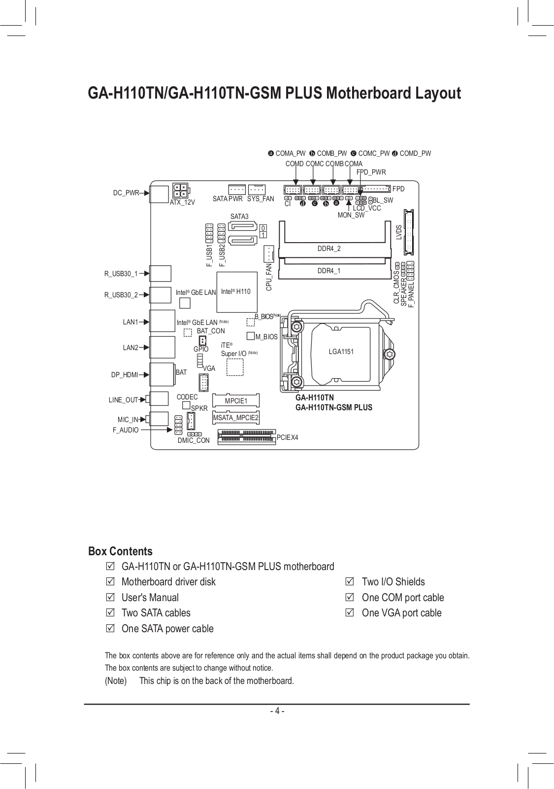
GA-H110TN
Service Manual
42 pgs
10.92 Mb
0
Table of contents
Loading...
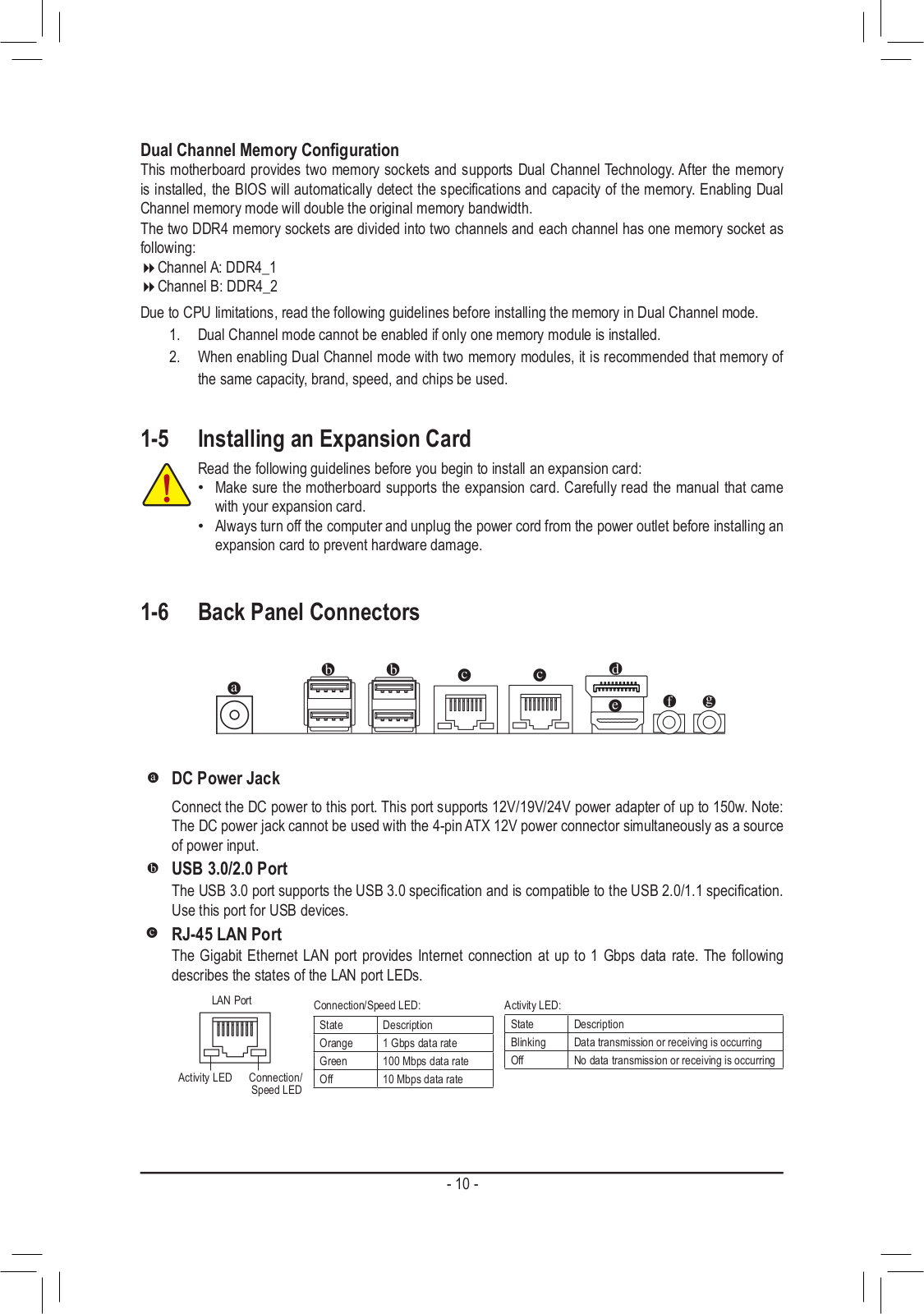
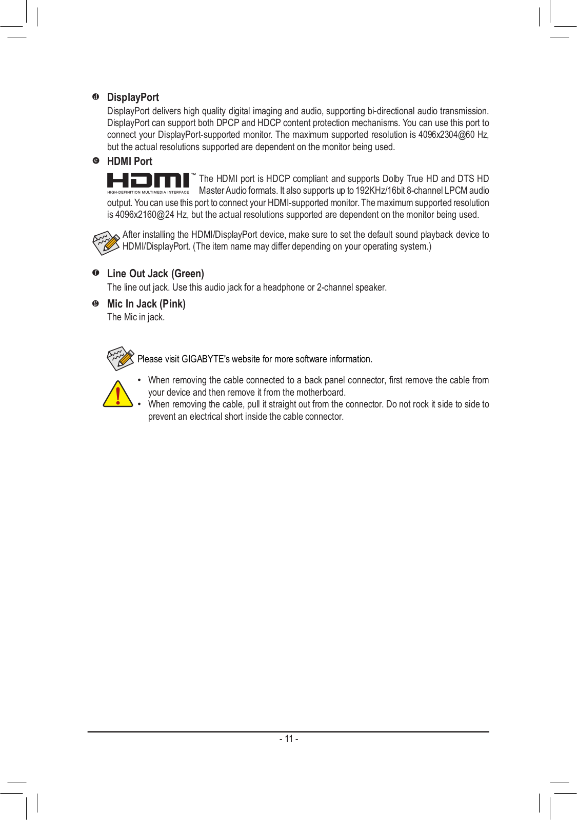
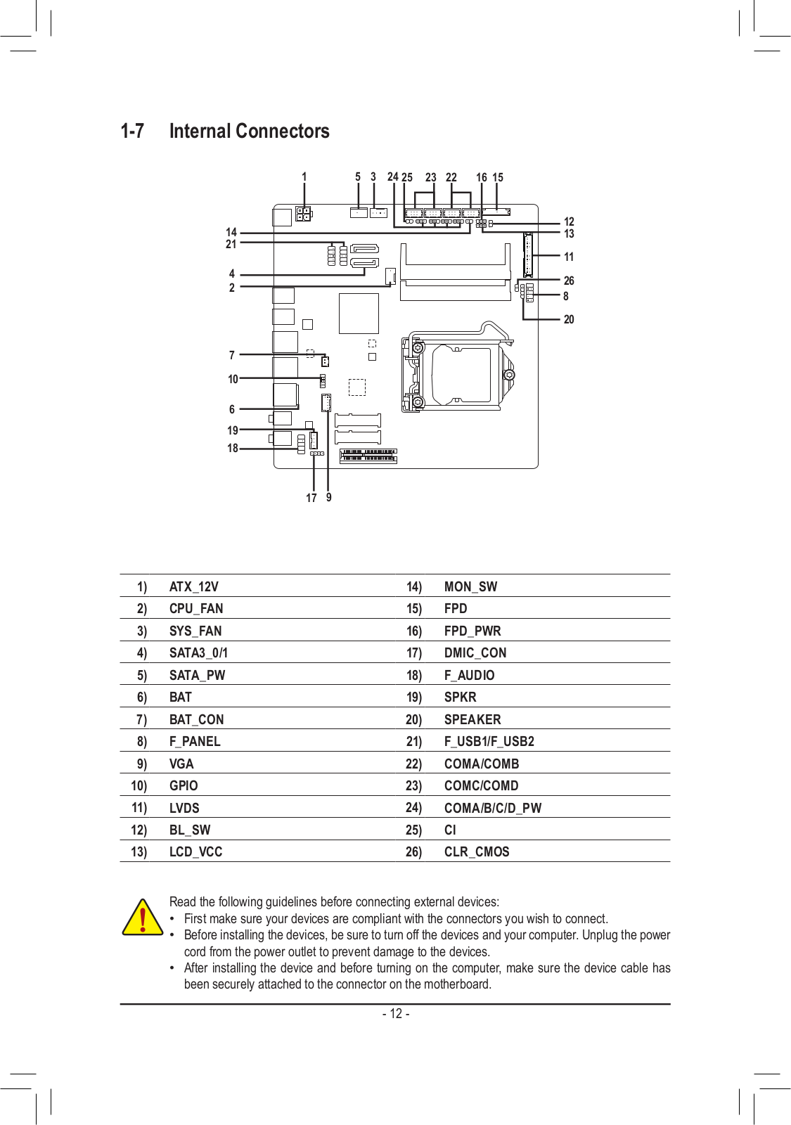
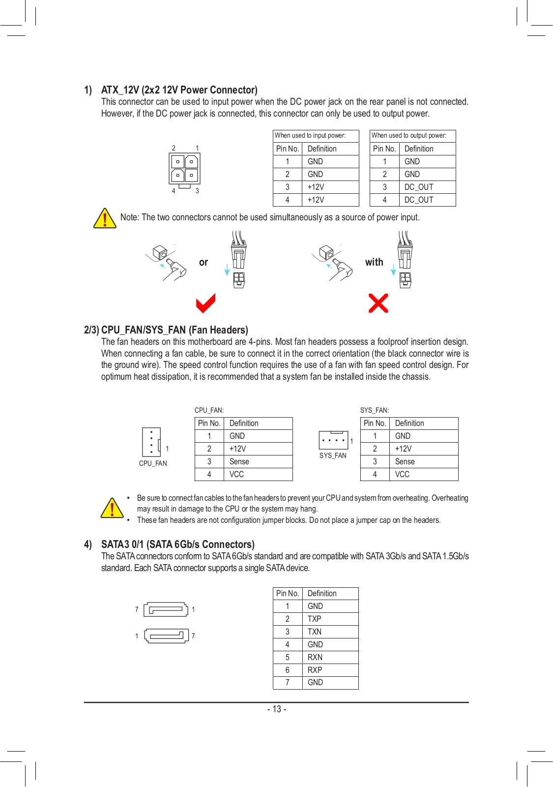
Gigabyte GA-H110TN Service Manual
...
Gigabyte Service Manual
Download
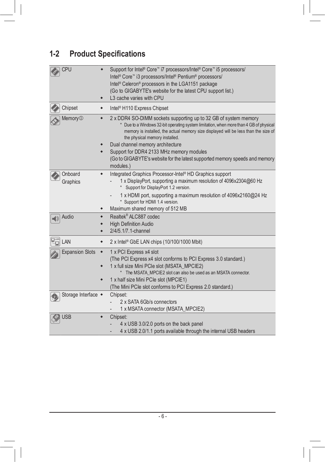
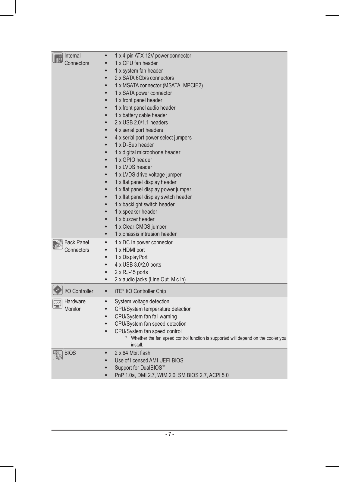
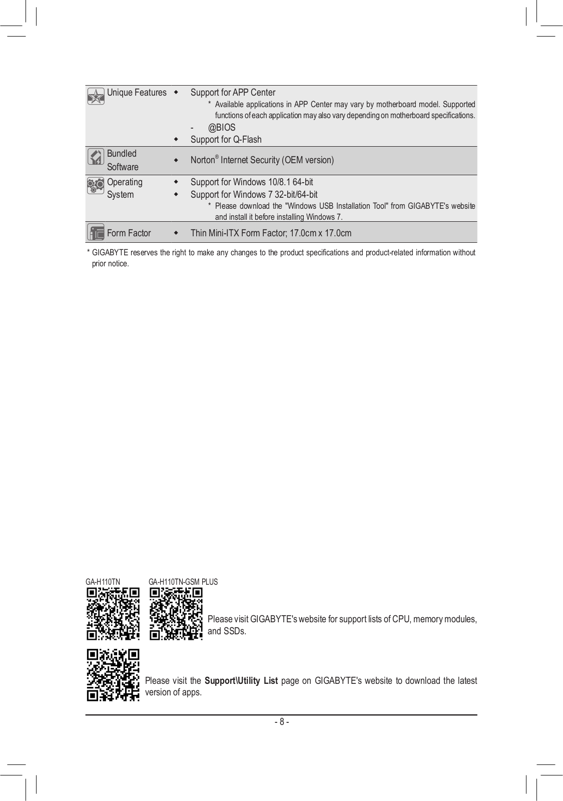
Specifications and Main Features
Frequently Asked Questions
User Manual
Download
Loading...
+
29
hidden pages
Unhide
You need points to download manuals.
1 point = 1 manual.
You can buy points or you can get point for every manual you upload.
Buy points
Upload your manuals
 Loading...