


GA-EX58-UD4
LGA1366 socket motherboard for Intel® Core
User's Manual
Rev. 1002
12ME-EX58U4-1002R
TM
i7 processor family

Dec. 12, 2008
Motherboard
GA-EX58-UD4
Dec. 12, 2008
GA-EX58-UD4
Motherboard
Copyright
© 2008 GIGA-BYTE TECHNOLOGY CO., LTD. All rights reserved.
The trademarks mentioned in this manual are legally registered to their respective owners.
Disclaimer
Information in this manual is protected by copyright laws and is the property of GIGABYTE.
Changes to the specifications and features in this manual may be made by GIGABYTE without prior
notice. No part of this manual may be reproduced, copied, translated, transmitted, or published in any
form or by any means without GIGABYTE's prior written permission.
Documentation Classifications
In order to assist in the use of this product, GIGABYTE provides the following types of documentations:
For quick set-up of the product, read the Quick Installation Guide included with the product.
For detailed product information, carefully read the User's Manual.
For instructions on how to use GIGABYTE's unique features, read or download the
information on/from the Support\Motherboard\Technology Guide page on our website.
For product-related information, check on our website at:
http://www.gigabyte.com.tw
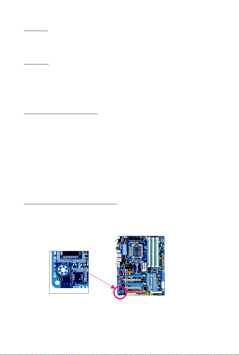
Identifying Your Motherboard Revision
The revision number on your motherboard looks like this: "REV: X.X." For example, "REV: 1.0"
means the revision of the motherboard is 1.0. Check your motherboard revision before updating
motherboard BIOS, drivers, or when looking for technical information.
Example:

Table of Contents
Box Contents ................................................................................................................. 6
Optional Items................................................................................................................. 6
GA-EX58-UD4 Motherboard Layout .............................................................................. 7
Block Diagram ................................................................................................................ 8
Chapter 1 Hardware Installation .................................................................................... 9
1-1 Installation Precautions ..................................................................................... 9
1-2 Product Specifications .................................................................................... 10
1-3 Installing the CPU and CPU Cooler .............................................................. 13
1-3-1 Installing the CPU ................................................................................................ 13
1-3-2 Installing the CPU Cooler ................................................................................... 15
1-4 Installing the Memory ..................................................................................... 16
1-4-1 Dual/3 Channel Memory Configuration ............................................................ 16
1-4-2 Installing a Memory ............................................................................................. 17
1-5 Installing an Expansion Card ......................................................................... 18
1-6 Installing the SATA Bracket ............................................................................. 19
1-7 Back Panel Connectors ................................................................................. 20
1-8 Internal Connectors ........................................................................................ 22
Chapter 2 BIOS Setup ................................................................................................. 35
2-1 Startup Screen ................................................................................................ 36
2-2 The Main Menu .............................................................................................. 37
2-3 MB Intelligent Tweaker(M.I.T.) ....................................................................... 39
2-4 Standard CMOS Features ............................................................................. 49
2-5 Advanced BIOS Features .............................................................................. 51
2-6 Integrated Peripherals ..................................................................................... 53
2-7 Power Management Setup ............................................................................. 56
2-8 PC Health Status ........................................................................................... 58
2-9 Load Fail-Safe Defaults................................................................................... 60
2-10 Load Optimized Defaults................................................................................. 60
2-11 Set Supervisor/User Password ..................................................................... 61
2-12 Save & Exit Setup......................................................................................... 62
2-13 Exit Without Saving ....................................................................................... 62
- 4 -

Chapter 3 Drivers Installation ...................................................................................... 63
3-1 Installing Chipset Drivers ............................................................................... 63
3-2 Application Software ....................................................................................... 64
3-3 Technical Manuals .......................................................................................... 64
3-4 Contact........................................................................................................... 65
3-5 System ........................................................................................................... 65
3-6 Download Center............................................................................................ 66
Chapter 4 Unique Features ......................................................................................... 67
4-1 Xpress Recovery2 ......................................................................................... 67
4-2 BIOS Update Utilities ..................................................................................... 70
4-2-1 Updating the BIOS with the Q-Flash Utility ...................................................... 70
4-2-2 Updating the BIOS with the @BIOS Utility ....................................................... 73
4-3 EasyTune 6.................................................................................................... 74
4-4 Dynamic Energy Saver Advanced ................................................................ 75
4-5 Q-Share ......................................................................................................... 77
4-6 Time Repair .................................................................................................... 78
Chapter 5 Appendix .................................................................................................... 79
5-1 Configuring SATA Hard Drive(s) .................................................................... 79
5-1-1 Configuring Intel ICH10R SATA Controllers ...................................................... 79
5-1-2 Configuring GIGABYTE SATA2 SATA Controller ............................................. 85
5-1-3 Making a SATA RAID/AHCI Driver Diskette ..................................................... 91
5-1-4 Installing the SATA RAID/AHCI Driver and Operating System ...................... 92
5-2 Configuring Audio Input and Output ............................................................... 102
5-2-1 Configuring 2/4/5.1/7.1-Channel Audio .......................................................... 102
5-2-2 Configuring S/PDIF In/Out ................................................................................ 104
5-2-3 Configuring Microphone Recording ................................................................. 106
5-2-4 Using the Sound Recorder ............................................................................... 108
5-3 Troubleshooting ............................................................................................. 109
5-3-1 Frequently Asked Questions ........................................................................... 109
5-3-2 Troubleshooting Procedure .............................................................................. 110
5-4 Regulatory Statements .................................................................................. 112
- 5 -
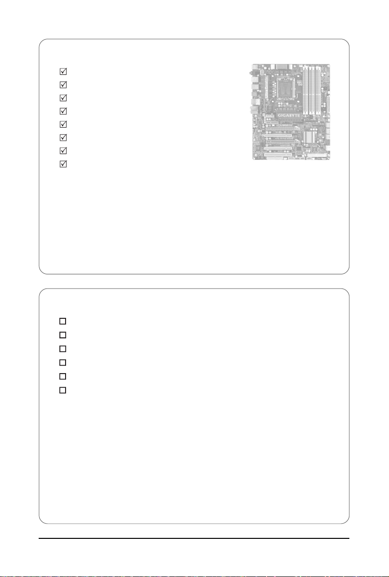
Box Contents
GA-EX58-UD4 motherboard
Motherboard driver disk
User's Manual
Quick Installation Guide
One IDE cable and one floppy disk drive cable
Four SATA 3Gb/s cables
One SA T A bracket
I/O Shield
• The box contents above are for reference only and the actual items shall depend on product package you obtain.
The box contents are subject to change without notice.
• The motherboard image is for reference only.
Optional Items
2-port USB 2.0 bracket (Part No. 12CR1-1UB030-5*R)
2-port IEEE 1394a bracket (Part No. 12CF1-1IE008-0*R)
2-port SATA power cable (Part No. 12CF1-2SERPW-0*R)
S/PDIF in cable (Part No. 12CR1-1SPDIN-0*R)
COM port cable (Part No. 12CF1-1CM001-3*R)
2-Way SLI bridge connector (Part No. 12CF1-SLI001-0*R)
- 6 -
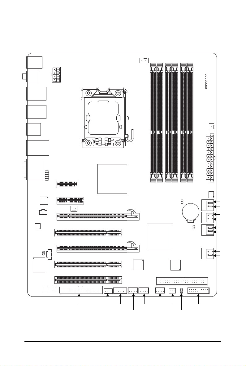
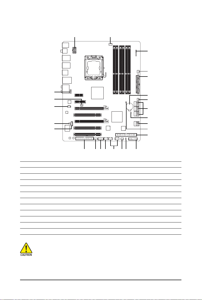
GA-EX58-UD4 Motherboard Layout
KB_MS
R_SPDIF
USB_1394_1
USB_1394_2
R_USB
USB_LAN
AUDIO
RTL8111D
SPDIF_I
CODEC
IT8720
M_BIOS
ATX_12V_2X
F_AUDIO
PCIEX1_1
PCIEX4_1
PCI1
CD_IN
SPDIF_O
PCI2
B_BIOS
NB_FAN
PCIEX16_2
PCI3
(Note)
LGA1366
Intel® X58
GA-EX58-UD4
PCIEX16_1
TSB43AB23
CPU_FAN
DDR3_2
DDR3_1
CLR_CMOS
Intel® ICH10R
DDR3_4
DDR3_3
GIGABYTE
SATA2
DDR3_6
DDR3_5
BATTERY
CI
PHASE LED
ATX
SYS_FAN1
IDE
PWR_FAN
SATA2_1
SATA2_0
SATA2_3
SATA2_2
SATA2_5
SATA2_4
GSATA2_1
GSATA2_0
FDD
COMA
SYS_FAN2
SYS_FAN3
F_USB1F1_1394
F_PANELF_USB2
PWR_LED
(Note) Due to a hardware limitation, the PCIEX1_1 slot can only accommodate a shorter PCI Express x1
expansion card. For a longer expansion card, use other expansion slots.
- 7 -
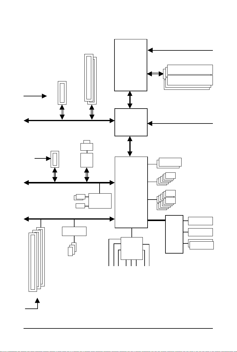
Block Diagram
1 PCI Express x4
PCIe CLK
(100 MHz)
x4
PCI Express Bus
1 PCI Express x1
PCIe CLK
(100 MHz)
x1 x1
PCI Express Bus
2 SATA 3Gb/s
ATA-133/100/66/33 IDE Channel
PCI Bus
2 PCI Express x16
x16
LAN
RJ45
RTL
8111D
x1
GIGABYTE
SATA2
LGA1366
Processor
Interface
®
Intel
X58
®
Intel
ICH10R
CPU CLK+/- (133 MHz)
DDR3 2000/1333/1066/800 MHz
Dual/3 Channel Memory
QPI
IOH CLK (133 MHz)
Dual BIOS
LPC Bus
6 SATA 3Gb/s
12 USB Ports
Floppy
3 PCI
PCI CLK
(33 MHz)
TSB43AB23
3 IEEE 1394a
CODEC
MIC
Line-In
Line-Out
S/PDIF In
S/PDIF Out
Side Speaker Out
Surround Speaker Out
Center/Subwoofer Speaker Out
- 8 -
IT8720
COM Port
PS/2 KB/Mouse

Chapter 1 Hardware Installation
1-1 Installation Precautions
The motherboard contains numerous delicate electronic circuits and components which can become
damaged as a result of electrostatic discharge (ESD). Prior to installation, carefully read the user's
manual and follow these procedures:
• Prior to installation, do not remove or break motherboard S/N (Serial Number) sticker or
warranty sticker provided by your dealer. These stickers are required for warranty validation.
• Always remove the AC power by unplugging the power cord from the power outlet before
installing or removing the motherboard or other hardware components.
• When connecting hardware components to the internal connectors on the motherboard,
make sure they are connected tightly and securely.
• When handling the motherboard, avoid touching any metal leads or connectors.
• It is best to wear an electrostatic discharge (ESD) wrist strap when handling electronic
components such as a motherboard, CPU or memory. If you do not have an ESD wrist strap,
keep your hands dry and first touch a metal object to eliminate static electricity.
• Prior to installing the motherboard, please have it on top of an antistatic pad or within an
electrostatic shielding container.
• Before unplugging the power supply cable from the motherboard, make sure the power supply
has been turned off.
• Before turning on the power, make sure the power supply voltage has been set according to
the local voltage standard.
• Before using the product, please verify that all cables and power connectors of your hardware
components are connected.
• To prevent damage to the motherboard, do not allow screws to come in contact with the
motherboard circuit or its components.
• Make sure there are no leftover screws or metal components placed on the motherboard or
within the computer casing.
• Do not place the computer system on an uneven surface
• Do not place the computer system in a high-temperature environment.
• Turning on the computer power during the installation process can lead to damage to system
components as well as physical harm to the user.
• If you are uncertain about any installation steps or have a problem related to the use of the
product, please consult a certified computer technician.
.
Hardware Installation- 9 -

1-2 Product Specifications
TM
CPU Support for an Intel® Core
(Go to GIGABYTE's website for the latest CPU support list.)
L3 cache varies with CPU
QPI 4.8GT/s, 6.4GT/s
Chipset North Bridge: Intel® X58 Express Chipset
South Bridge: Intel® ICH10R
Memory 6 x 1.5V DDR3 DIMM sockets supporting up to 24 GB of system memory
Dual/3 channel memory architecture
Support for DDR3 2000/1333/1066/800 MHz memory modules
(Go to GIGABYTE's website for the latest memory support list.)
Audio Realtek ALC888 codec
High Definition Audio
2/4/5.1/7.1-channel
Support for S/PDIF In/Out
Support for CD In
LAN 1 x Realtek 8111D chip (10/100/1000 Mbit)
Expansion Slots 2 x PCI Express x16 slot, running at x16
(The PCI Express slots support ATI CrossFireXTM technology and conform
to PCI Express 2.0 standard.)
1 x PCI Express x4 slot
1 x PCI Express x1 slot
3 x PCI slots
Storage Interface South Bridge:
- 6 x SATA 3Gb/s connectors (SATA2_0, SATA2_1, SATA2_2, SATA2_3,
SATA2_4, SATA2_5) supporting up to 6 SATA 3Gb/s devices
- Support for SATA RAID 0, RAID 1, RAID 5, and RAID 10
GIGABYTE SATA2 chip:
- 1 x IDE connector supporting ATA-133/100/66/33 and up to 2 IDE devices
- 2 x SATA 3Gb/s connectors (GSATA2_0, GSATA2_1) supporting up to 2
SATA 3Gb/s devices
- Support for SATA RAID 0, RAID 1 and JBOD
iTE IT8720 chip:
- 1 x floppy disk drive connector supporting up to 1 floppy disk drive
USB Integrated in the South Bridge
Up to 12 USB 2.0/1.1 ports (8 on the back panel, 4 via the USB brackets
connected to the internal USB headers)
IEEE 1394 T.I. TSB43AB23 chip
Up to 3 IEEE 1394a ports (2 on the back panel, 1 via the IEEE 1394a
bracket connected to the internal IEEE 1394a header)
i7 series processor in the LGA 1366 package
(Note 1)
GA-EX58-UD4 Motherboard - 10 -

Internal Connectors 1 x 24-pin ATX main power connector
1 x 8-pin ATX 12V power connector
1 x floppy disk drive connector
1 x IDE connector
8 x SATA 3Gb/s connectors
1 x CPU fan header
3 x system fan headers
1 x power fan header
1 x North Bridge fan header
1 x front panel header
1 x front panel audio header
1 x CD In connector
1 x S/PDIF In header
1 x S/PDIF Out header
2 x USB 2.0/1.1 headers
1 x IEEE 1394a header
1 x serial port header
1 x power LED header
1 x chassis intrusion header
1 x clearing CMOS jumper
Back Panel 1 x PS/2 keyboard port
Connectors 1 x PS/2 mouse port
1 x coaxial S/PDIF Out connector
1 x optical S/PDIF Out connector
2 x IEEE 1394a ports
8 x USB 2.0/1.1 ports
1 x RJ-45 port
6 x audio jacks (Center/Subwoofer Speaker Out/Rear Speaker Out/Side
Speaker Out/Line In/Line Out/Microphone)
I/O Controller iTE IT8720 chip
Hardware Monitor System voltage detection
CPU/System/North Bridge temperature detection
CPU/System/Power fan speed detection
CPU overheating warning
CPU/System/Power fan fail warning
CPU/System fan speed control
(Note 2)
Hardware Installation- 11 -

BIOS 2 x 8 Mbit flash
Use of licensed AWARD BIOS
Support for DualBIOS
TM
PnP 1.0a, DMI 2.0, SM BIOS 2.4, ACPI 1.0b
Unique Features Support for @BIOS
Support for Q-Flash
Support for Virtual Dual BIOS
Support for Download Center
Support for Xpress Install
Support for Xpress Recovery2
Support for EasyTune
(Note 3)
Support for Dynamic Energy Saver Advanced
Support for Time Repair
Support for Q-Share
Bundled Software Norton Internet Security (OEM version)
Operating System Support for Microsoft® Windows® Vista/XP
Form Factor ATX Form Factor; 30.5cm x 24.4cm
(Note 1) Due to Windows Vista/XP 32-bit operating system limitation, when more than 4 GB of physical
memory is installed, the actual memory size displayed will be less than 4 GB.
(Note 2) Whether the CPU/system fan speed control function is supported will depend on the CPU/
system cooler you install.
(Note 3) Available functions in EasyTune may differ by motherboard model.
GA-EX58-UD4 Motherboard - 12 -
1-3 Installing the CPU and CPU Cooler
Read the following guidelines before you begin to install the CPU:
• Make sure that the motherboard supports the CPU.
(Go to GIGABYTE's website for the latest CPU support list.)
• Always turn off the computer and unplug the power cord from the power outlet before
installing the CPU to prevent hardware damage.
• Locate the pin one of the CPU. The CPU cannot be inserted if oriented incorrectly. (Or you
may locate the notches on both sides of the CPU and alignment keys on the CPU socket.)
• Apply an even and thin layer of thermal grease on the surface of the CPU.
• Do not turn on the computer if the CPU cooler is not installed, otherwise overheating and
damage of the CPU may occur.
• Set the CPU host frequency in accordance with the CPU specifications. It is not recom-
mended that the system bus frequency be set beyond hardware specifications since it
does not meet the standard requirements for the peripherals. If you wish to set the frequency
beyond the standard specifications, please do so according to your hardware specifications including the CPU, graphics card, memory, hard drive, etc.
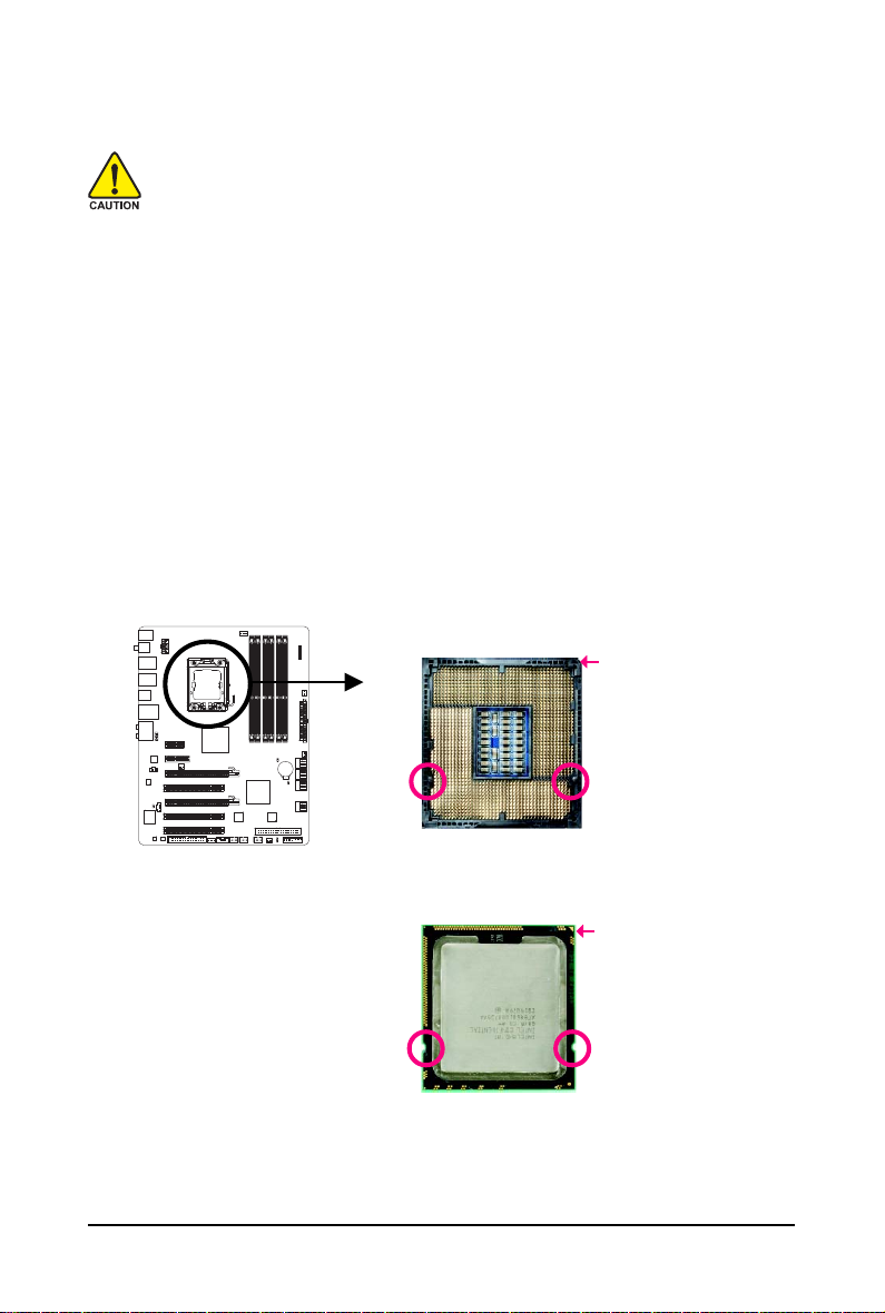
1-3-1 Installing the CPU
A. Locate the alignment keys on the motherboard CPU socket and the notches on the CPU.
LGA1366 CPUSocket
Pin One Corner of the CPU Socket
Alignment Key Alignment Key
LGA1366 CPU
Triangle Pin One Marking on the CPU
NotchNotch
Hardware Installation- 13 -
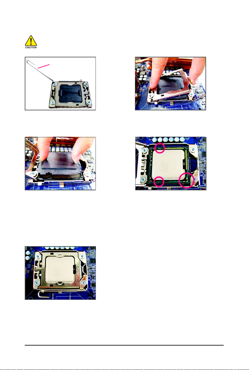
B. Follow the steps below to correctly install the CPU into the motherboard CPU socket.
Before installing the CPU, make sure to turn off the computer and unplug the power
cord from the power outlet to prevent damage to the CPU.
CPU Socket Lever
Step 1:
Completely raise the CPU socket lever.
Step 3:
Use your thumb and index finger to hold the
protective socket cover as indicated and lift it
up vertically. (DO NOT touch socket contacts.
To protect the CPU socket, always replace the
protective socket cover when the CPU is not
installed.)
Step 2:
Lift the metal load plate from the CPU socket.
Step 4:
Hold the CPU with your thumb and index finger.
Align the CPU pin one marking (triangle) with
the pin one corner of the CPU socket (or you
may align the CPU notches with the socket
alignment keys) and gently insert the CPU
into position.
Step 5:
Once the CPU is properly inserted, replace
the load plate and push the CPU socket lever
back into its locked position.
GA-EX58-UD4 Motherboard - 14 -
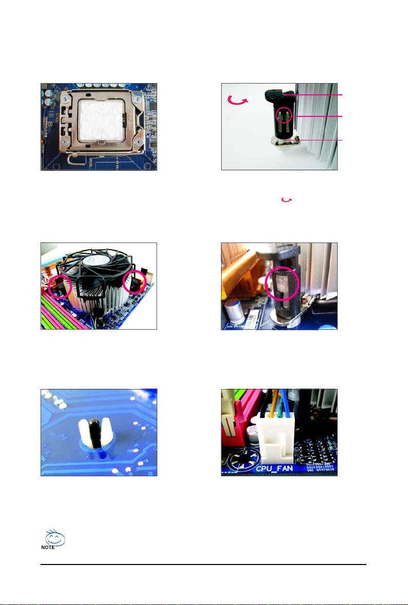
1-3-2 Installing the CPU Cooler
Follow the steps below to correctly install the CPU cooler on the motherboard. (The following procedure
uses Intel® boxed cooler as the example cooler.)
Male
Direction of
the Arrow
Sign on the
Male Push
Pin
Push Pin
The Top of
Female
Push Pin
Female
Push Pin
Step 1:
Apply an even and thin layer of thermal grease
on the surface of the installed CPU.
Step 3:
Place the cooler atop the CPU, aligning the
four push pins through the pin holes on the
motherboard. Push down on the push pins
diagonally.
Step 2:
Before installing the cooler, note the direction
of the arrow sign on the male push pin.
(Turning the push pin along the direction of
arrow is to remove the cooler, on the contrary,
is to install.)
Step 4:
You should hear a "click" when pushing down each
push pin. Check that the Male and Female push pins
are joined closely. (Refer to your CPU cooler installation manual for instructions on installing the cooler.)
Step 5:
After the installation, check the back of the
motherboard. If the push pin is inserted as the
picture above shows, the installation is complete.
Step 6:
Finally, attach the power connector of the CPU
cooler to the CPU fan header (CPU_FAN) on
the motherboard.
Use extreme care when removing the CPU cooler because the thermal grease/tape between
the CPU cooler and CPU may adhere to the CPU. Inadequately removing the CPU cooler may
damage the CPU.
Hardware Installation- 15 -
1-4 Installing the Memory
Read the following guidelines before you begin to install the memory:
• Make sure that the motherboard supports the memory. It is recommended that memory of
the same capacity, brand, speed, and chips be used.
(Go to GIGABYTE's website for the latest memory support list.)
• Always turn off the computer and unplug the power cord from the power outlet before
installing the memory to prevent hardware damage.
• Memory modules have a foolproof design. A memory module can be installed in only one
direction. If you are unable to insert the memory, switch the direction.
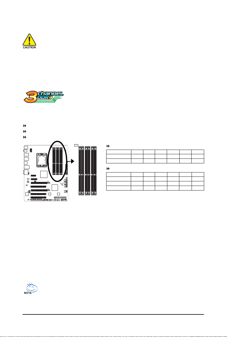
1-4-1 Dual/3 Channel Memory Configuration
This motherboard provides six DDR3 memory sockets and supports Dual/3
Channel Technology. After the memory is installed, the BIOS will automatically
memory mode may double or triple the original memory bandwidth.
The six DDR3 memory sockets are divided into three channels and each channel has two memory
sockets as following:
Channel 0: DDR3_1, DDR3_2
Channel 1: DDR3_3, DDR3_4
Channel 2: DDR3_5, DDR3_6
detect the specifications and capacity of the memory. Dual or 3 Channel
Dual Channel Memory Configurations Table
Two Modules
Four Modules
3 Channel Memory Configurations Table
Three Modules
Four Modules
Six Modules
(SS=Single-Sided, DS=Double-Sided, "- -"=No Memory)
DDR3_2 DDR3_1 DDR3_4 DDR3_3 DDR3_6 DDR3_5
- - DS/SS - - DS/SS - - - -
DS/SS DS/SS DS/SS DS/SS - - - -
DDR3_2 DDR3_1 DDR3_4 DDR3_3 DDR3_6 DDR3_5
- - DS/SS - - DS/SS - - DS/SS
DS/SS DS/SS - - DS/SS - - DS/SS
DS/SS DS/SS DS/SS DS/SS DS/SS DS/SS
DDR3_2
DDR3_1
DDR3_4
DDR3_3
DDR3_6
DDR3_5
Due to chipset limitation, read the following guidelines before installing the memory in Dual or 3 Channel mode.
Dual Channel--
1. Dual Channel mode cannot be enabled if only one DDR3 memory module is installed.
2. When enabling Dual Channel mode with two or four modules, it is recommended that memory of
the same capacity, brand, speed, and chips be used. When enabling Dual Channel mode with two
memory modules, be sure to install them in the DDR3_1 and DDR3_3 sockets.
3 Channel--
1. 3 Channel mode cannot be enabled if only one or two DDR3 memory modules are installed.
2. When enabling 3 Channel mode with three, four or six modules, it is recommended that memory
of the same capacity, brand, speed, and chips be used.
When enabling 3 Channel mode with three memory modules, be sure to install them in the
DDR3_1, DDR3_3 and DDR3_5 sockets.
When enabling 3 Channel mode with four memory modules, be sure to install them in the
DDR3_1, DDR3_2, DDR3_3 and DDR3_5 sockets.
• If only one DDR3 memory module is installed, be sure to install it in the DDR3_1 or DDR3_3.
• When memory modules of different capacity and chips are installed, a message which
says memory is operating in Flex Memory Mode will appear during the POST. Intel® Flex
Memory Technology offers greater flexibility to upgrade by allowing dif ferent memory sizes
to be populated and remain in Dual/3 Channel mode/performance.
GA-EX58-UD4 Motherboard - 16 -
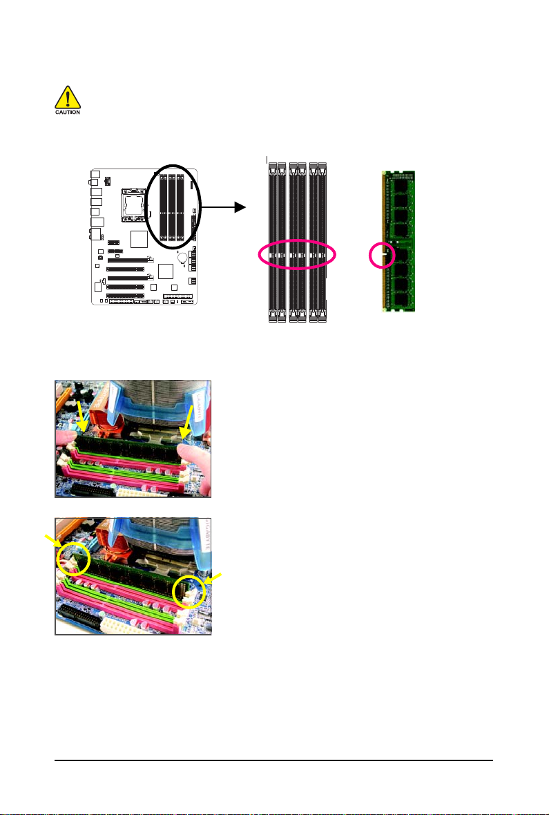
1-4-2 Installing a Memory
Before installing a memory module , make sure to turn off the computer and unplug
the power cord from the power outlet to prevent damage to the memory module.
DDR3 and DDR2 DIMMs are not compatible to each other or DDR DIMMs. Be sure to
install DDR3 DIMMs on this motherboard.
Notch
DDR3 DIMM
A DDR3 memory module has a notch, so it can only fit in one direction. Follow the steps below to
correctly install your memory modules in the memory sockets.
Step 1:
Note the orientation of the memory module. Spread the retaining
clips at both ends of the memory socket. Place the memory
module on the socket. As indicated in the picture on the left,
place your fingers on the top edge of the memory, push down
on the memory and insert it vertically into the memory socket.
Step 2:
The clips at both ends of the socket will snap into place when
the memory module is securely inserted.
Hardware Installation- 17 -
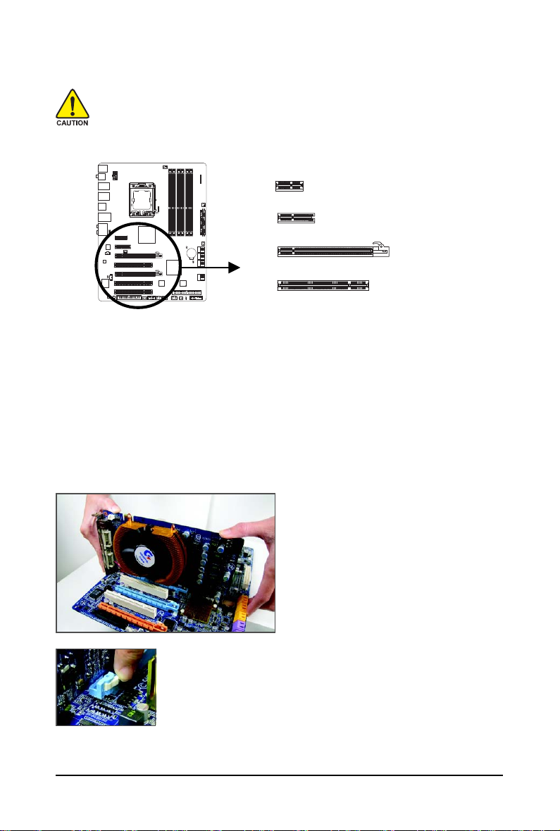
1-5 Installing an Expansion Card
Read the following guidelines before you begin to install an expansion card:
• Make sure the motherboard supports the expansion card. Carefully read the manual that
came with your expansion card.
• Always turn off the computer and unplug the power cord from the power outlet before
installing an expansion card to prevent hardware damage.
PCI Express x1 Slot
PCI Express x4 Slot
PCI Express x16 Slot
PCI Slot
Follow the steps below to correctly install your expansion card in the expansion slot.
1. Locate an expansion slot that supports your card. Remove the metal slot cover from the chassis back panel.
2. Align the card with the slot, and press down on the card until it is fully seated in the slot.
3. Make sure the metal contacts on the card are completely inserted into the slot.
4. Secure the card's metal bracket to the chassis back panel with a screw.
5. After installing all expansion cards, replace the chassis cover(s).
6. Turn on your computer. If necessary, go to BIOS Setup to make any required BIOS changes for
your expansion card(s).
7. Install the driver provided with the expansion card in your operating system.
Example: Installing and Removing a PCI Express x16 Graphics Card:
• Installing a Graphics Card:
Gently push down on the top edge of the card
until it is fully inserted into the PCI Express slot.
Make sure the card is securely seated in the
slot and does not rock.
• Removing the Card:
Press the white latch at the end of the PCI Express slot to release the card
and then pull the card straight up from the slot.
GA-EX58-UD4 Motherboard - 18 -
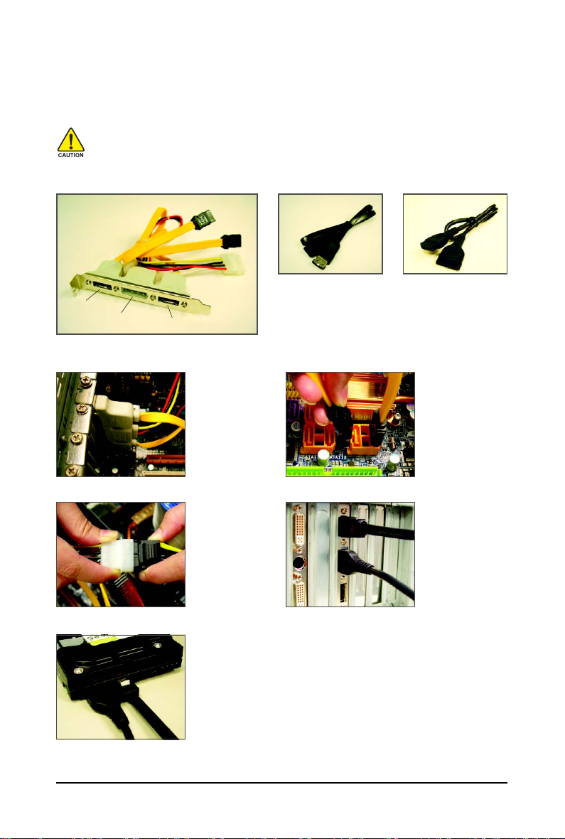
1-6 Installing the SA TA Bracket
The SATA bracket allows you to connect external SA TA device(s) to your system by expanding the
internal SATA port(s) to the chassis back panel.
• Turn off your system and the power switch on the power supply before installing or
removing the SATA bracket and SATA power cable to prevent damage to hardware.
• Insert the SATA signal cable and SATA power cable securely into the corresponding connec-
tors when installing.
SATA Bracket
External
SATA
Connector
Power
Connector
External SATA
Connector
Follow the steps below to install the SA TA bracket:
Step 1:
Locate one free PCI
slot and secure the
SATA bracket to the
chassis back panel
with a screw.
Step 3:
Connect the power
cable from the bracket
to the power supply.
Step 5:
Connect the other ends of the SATA signal cable and SATA power cable
to your SATA device. For SATA device in external enclosure, you only
need to connect the SATA signal cable. Before connecting the SATA signal
cable, make sure to turn off the power of the external enclosure.
SATA Power CableSATA Signal Cable
The SATA bracket includes one SATA bracket, one
SATA signal cable, and one SATA power cable.
Step 2:
Connect the SA TA
cable from the bracket
to the SA TA port on
your motherboard.
Step 4:
Plug one end of the
SATA signal cable into
the external SATA connector on the bracket.
Then attach the SATA
power cable to the
power connector on
the bracket.
Hardware Installation- 19 -
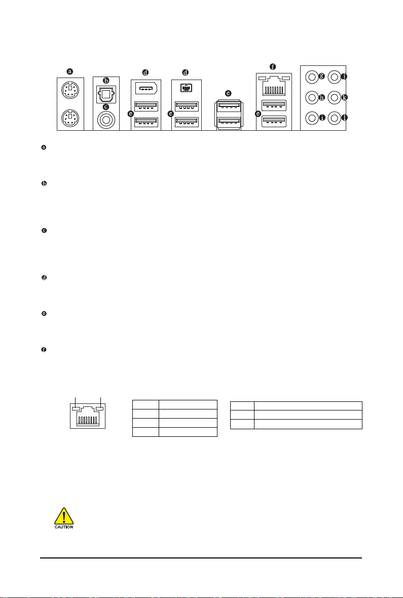
1-7 Back Panel Connectors
PS/2 Keyboard and PS/2 Mouse Port
Use the upper port (green) to connect a PS/2 mouse and the lower port (purple) to connect a PS/2
keyboard.
Optical S/PDIF Out Connector
This connector provides digital audio out to an external audio system that supports digital optical
audio. Before using this feature, ensure that your audio system provides a n optical digital audio in
connector.
Coaxial S/PDIF Out Connector
This connector provides digital audio out to an external audio system that supports digital coaxial
audio. Before using this feature, ensure that your audio system provides a coaxial digital audio in
connector.
IEEE 1394a Port
The IEEE 1394 port supports the IEEE 1394a specification, featuring high speed, high bandwidth
and hotplug capabilities. Use this port for an IEEE 1394a device.
USB Port
The USB port supports the USB 2.0/1.1 specification. Use this port for USB devices such as an
USB keyboard/mouse, USB printer, USB flash drive and etc.
RJ-45 LAN Port
The Gigabit Ethernet LAN port provides Internet connection at up to 1 Gbps data rate. The following
describes the states of the LAN port LEDs.
Connection/
Speed LED
LAN Port
Activity LED
Connection/Speed LED:
State Description
Orange 1 Gbps data rate
Green 100 Mbps data rate
Off 10 Mbps data rate
Activity LED:
State Description
Blinking Data transmission or receiving is occurring
Off No data transmission or receiving is occurring
• When removing the cable connected to a back panel connector, first remove the cable
from your device and then remove it from the motherboard.
• When removing the cable, pull it straight out from the connector. Do not rock it side to side
to prevent an electrical short inside the cable connector.
GA-EX58-UD4 Motherboard - 20 -

Center/Subwoofer Speaker Out Jack (Orange)
Use this audio jack to connect center/subwoofer speakers in a 5.1/7.1-channel audio configuration.
Rear Speaker Out Jack (Black)
Use this audio jack to connect rear speakers in a 4/5.1/7.1-channel audio configuration.
Side Speaker Out Jack (Gray)
Use this audio jack to connect side speakers in a 7.1-channel audio configuration.
Line In Jack (Blue)
The default line in jack. Use this audio jack for line in devices such as an optical drive, walkman, etc.
Line Out Jack (Green)
The default line out jack. Use this audio jack for a headphone or 2-channel speaker. This jack can
be used to connect front speakers in a 4/5.1/7.1-channel audio configuration.
Mic In Jack (Pink)
The default Mic in jack. Microphones must be connected to this jack.
In addition to the default speakers settings, the ~ audio jacks can be reconfigured to
perform different functions via the audio software. Only microphones still MUST be
connected to the default Mic in jack ( ). Refer to the instructions on setting up a 2/4/5.1/
7.1-channel audio configuration in Chapter 5, "Configuring 2/4/5.1/7.1-Channel Audio."
Hardware Installation- 21 -
1-8 Internal Connectors
14
6
16
15
1) ATX_12V_2X
2) ATX
3) CPU_FAN
4) SYS_FAN1/2/3
5) PWR_FAN
6) NB_FAN
7) FDD
8) IDE
9) SATA2_0/1/2/3/4/5
10) GSATA2_0/1
11) PWR_LED
12) BATTERY
1
7
3
191718
20 4
4
23
5
2
12
4
9
21
10
22
8
13
11
13) F_PANEL
14) F_AUDIO
15) CD_IN
16) SPDIF_I
17) SPDIF_O
18) F_USB1/F_USB2
19) F1_1394
20) COMA
21) CI
22) CLR_CMOS
23) PHASE_LED
Read the following guidelines before connecting external devices:
• First make sure your devices are compliant with the connectors you wish to connect.
• Before installing the devices, be sure to turn off the devices and your computer. Unplug the
power cord from the power outlet to prevent damage to the devices.
• After installing the device and before turning on the computer, make sure the device cable
has been securely attached to the connector on the motherboard.
GA-EX58-UD4 Motherboard - 22 -
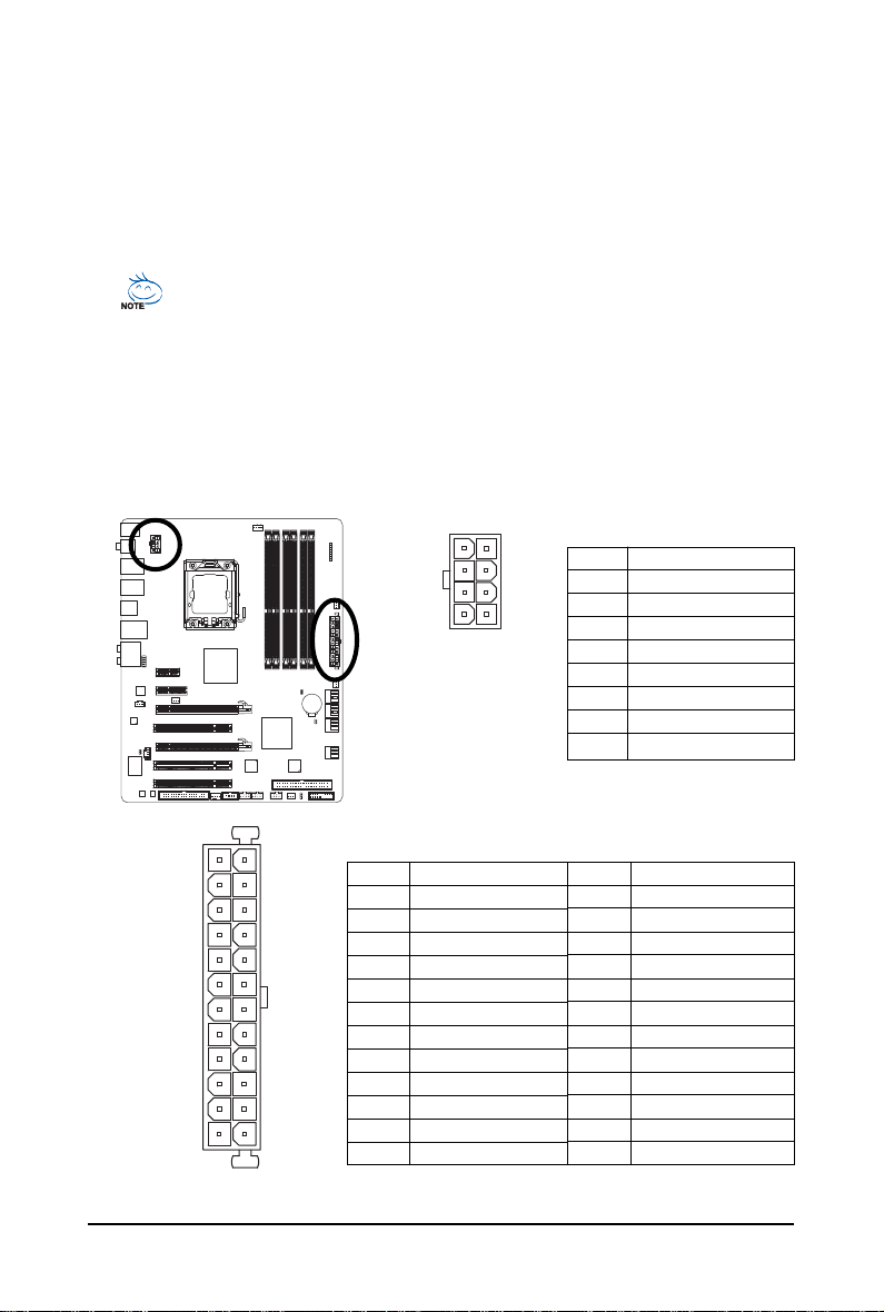
1/2) ATX_12V_2X/ATX (2x4 12V Power Connector and 2x12 Main Power Connector)
With the use of the power connector, the power supply can supply enough stable power to all the
components on the motherboard. Before connecting the power connector, first make sure the
power supply is turned off and all devices are properly installed. The power connector possesses
a foolproof design. Connect the power supply cable to the power connector in the correct orientation.
The 12V power connector mainly supplies power to the CPU. If the 12V power connector is not
connected, the computer will not start.
• Use of a power supply providing a 2x4 12V power connector is recommended by the
CPU manufacturer when using an Intel Extreme Edition CPU (130W).
• To meet expansion requirements, it is recommended that a power supply that can withstand
high power consumption be used (500W or greater). If a power supply is used that does not
provide the required power, the result can lead to an unstable or unbootable system.
• The power connectors are compatible with power supplies with 2x2 12V and 2x10 power
connectors. When using a power supply providing a 2x4 12V and a 2x12 power connector,
remove the protective covers from the 12V power connector and the main power connector on
the motherboard. Do not insert the power supply cable s into pins under the protective covers
when using a power supply providing a 2x2 12V and a 2x10 power connector.
ATX_12V_2X:
8
5
ATX_12V_2X
4
Pin No. Definition
1 GND (Only for 2x4 pin 12V)
1
2 GND (Only for 2x4 pin 12V)
3 GND
4 GND
5 +12V (Only for 2x4 pin 12V)
6 +12V (Only for 2x4 pin 12V)
7 +12V
8 +12V
12
24
131
ATX
ATX :
Pin No. Definition
1 3.3V
2 3.3V
3 GND
4 +5V
5 GND
6 +5V
7 GND
8 Power Good
9 5V SB(stand by +5V)
10 +12V
11 +12V (Only for 2x12 pin ATX)
12 3.3V (Only for 2x12 pin ATX)
Pin No. Definition
13 3.3V
14 -12V
15 GND
16 PS_ON(soft On/Off)
17 GND
18 GND
19 GND
20 -5V
21 +5V
22 +5V
23 +5V (Only for 2x12 pin ATX)
24 GND (Only for 2x12 pin ATX)
Hardware Installation- 23 -
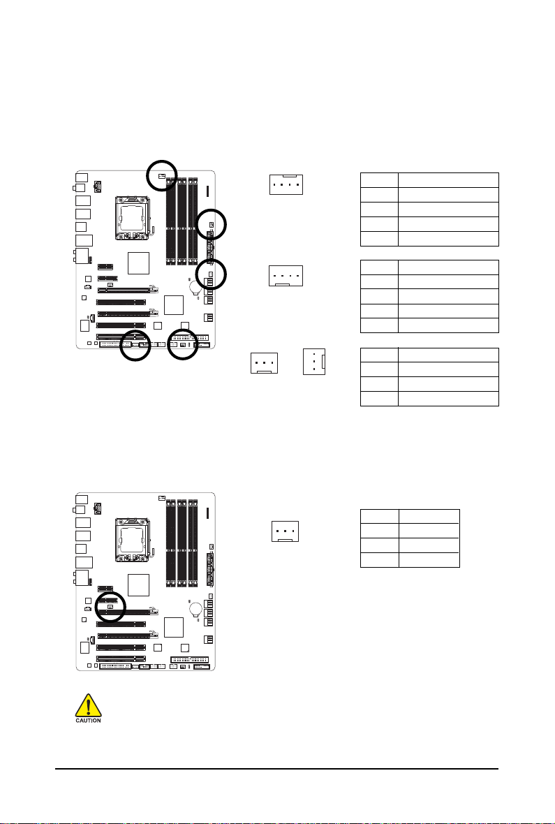
3/4/5) CPU_FAN / SYS_FAN1 / SYS_FAN2 / SYS_FAN3 / PWR_FAN (Fan Headers)
The motherboard has a 4-pin CPU fan header (C PU_FAN), a 4-pin (SYS_ FAN2) and two 3-pin
(SYS_FAN1/SYS_FAN3) system fan headers, and a 3-pin power fan header (PWR_FAN). Most fan
headers possess a foolproof insertion design. When connecting a fan cable, be sure to connect it in
the correct orientation (the black connector wire is the ground wire). The motherboard supports CPU
fan speed control, which requires the use of a CPU fan with fan speed control design . For optimum
heat dissipation, it is recommended that a system fan be installed inside the chassis.
CPU_FAN:
SYS_FAN2:
SYS_FAN1/PWR_FAN:
1
Pin No. Definition
1 GND
2 +12V / Speed Control
3 Sense
4 Speed Control
Pin No. Definition
1 GND
2 +12V / Speed Control
3 Sense
4 Reserve
Pin No. Definition
1 GND
2 +12V
3 Sense
1
1
SYS_FAN3
1
CPU_FAN
SYS_FAN2
SYS_FAN1/
PWR_FAN
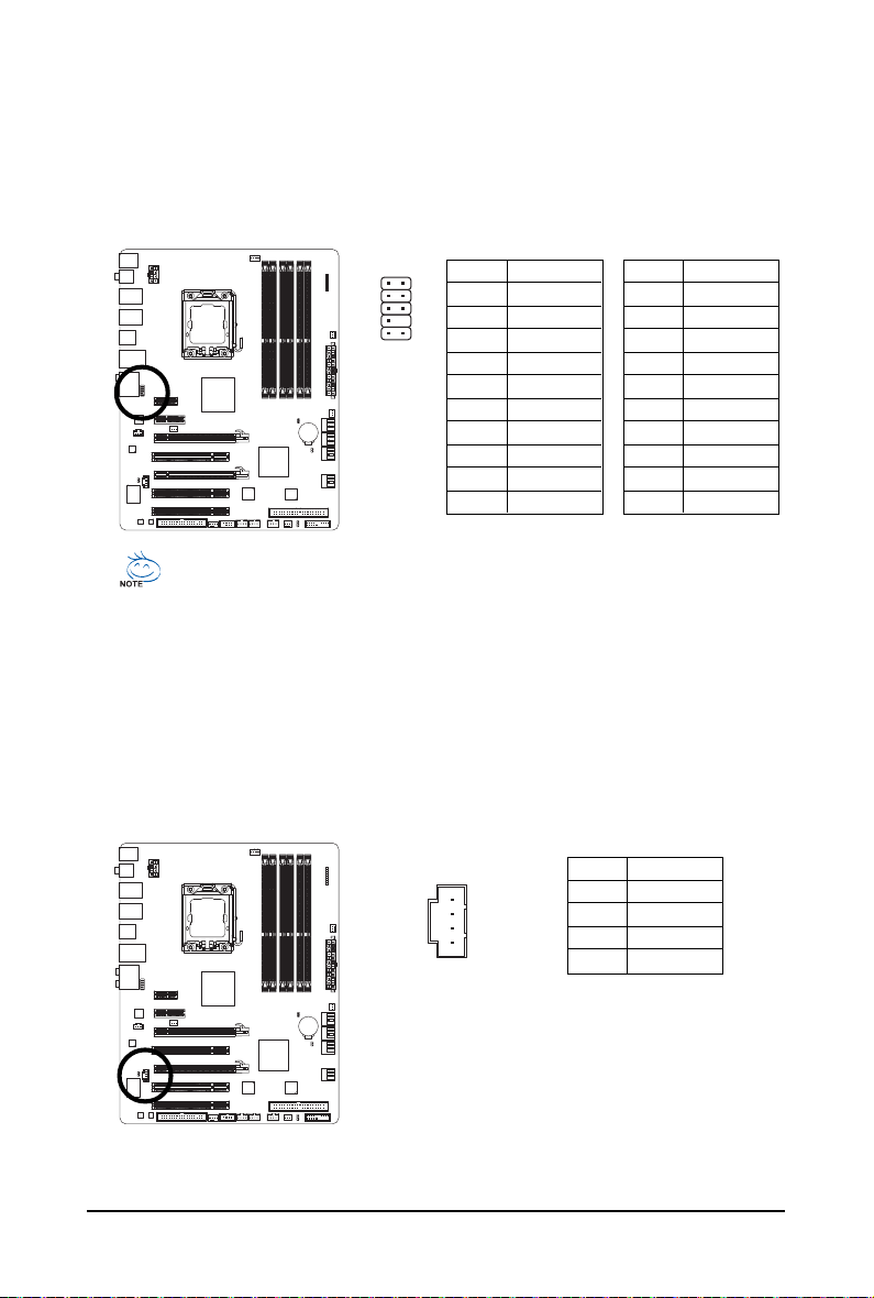
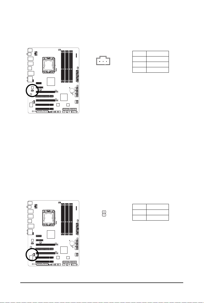
6) NB_FAN (North Bridge Fan Header)
Connect the North Bridge fan cable to this header. The fan header has a foolproof insertion design.
When connecting a fan cable, be sure to connect it in the correct orientation. Most fans are designed
with color-coded power connector wires. A red power connector wire indicates a positive connection and requires a +12V voltage. The black connector wire is the ground wire.
1
• Be sure to connect fan cables to the fan headers to prevent your CPU, North Bridge and
system from overheating. Overheating may result in damage to the CPU/North Bridge or
the system may hang.
• These fan headers are not configuration jumper blocks. Do not place a jumper cap on the
headers.
GA-EX58-UD4 Motherboard - 24 -
Pin No. Definition
1 GND
2 +12V
3NC
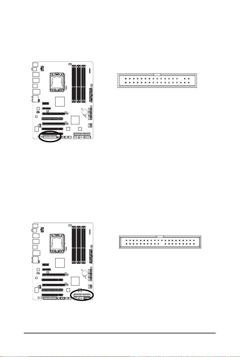
7) FDD (Floppy Disk Drive Connector)
This connector is used to connect a floppy disk drive. The types of floppy disk drives supported
are: 360 KB, 720 KB, 1.2 MB, 1.44 MB, and 2.88 MB. Before connecting a floppy disk drive, be
sure to locate pin 1 of the connector and the floppy disk drive cable. The pin 1 of the cable is
typically designated by a stripe of different color.
33
34
1
2
8) IDE (IDE Connector)
The IDE connector supports up to two IDE devices such as hard drives and optical drives. Before
attaching the IDE cable, locate the foolproof groove on the connector. If you wish to connect two IDE
devices, remember to set the jumpers and the cabling according to the role of the IDE devices (for
example, master or slave). (For information about configuring master/slave settings for the IDE
devices, read the instructions from the device manufacturers.)
39
1
40
2
Hardware Installation- 25 -
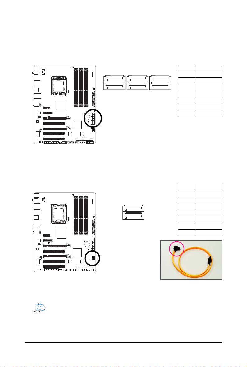
9) SATA2_0/1/2/3/4/5 (SATA 3Gb/s Connectors, Controlled by ICH10R, Blue)
The SATA connectors conform to SATA 3Gb/s standard and are compatible with SA TA 1.5Gb/s
standard. Each SATA connector supports a single SATA device. The ICH10R controller supports
RAID 0, RAID 1, RAID 5 and RAID 10. Refer to Chapter 5, "Configuring SA TA Hard Drive(s)," for
instructions on configuring a RAID array.
Pin No. Definition
1 GND
1
2TXP
1
3 TXN
4 GND
5 RXN
6 RXP
7 GND
7
7
SATA2_5
SATA2_4
SATA2_3
SATA2_2
SATA2_1
SATA2_0
10 ) GSATA2_0/1 (SATA 3Gb/s Connectors, Controlled by GIGABYTE SATA2, White)
The SATA connectors conform to SATA 3Gb/s standard and are compatible with SA TA 1.5Gb/s
standard. Each SATA connector supports a single SATA device. The GIGABYTE SATA2 controller
supports RAID 0, RAID 1 and JBOD. Refer to Chapter 5, "Configuring SA TA Hard Drive(s)," for
instructions on configuring a RAID array.
7
7
GSATA2_1
1
1
GSATA2_0
Pin No. Definition
1 GND
2 TXP
3 TXN
4 GND
5 RXN
6 RXP
7 GND
• A RAID 0 or RAID 1 configuration requires at least two hard drives. If more than two hard
drives are to be used, the total number of hard drives must be an even number.
• A RAID 5 configuration requires at least three hard drives. (The total number of hard
drives does not have to be an even number.)
• A RAID 10 configuration requires at least four hard drives and the total number of hard
drives must be an even number.
GA-EX58-UD4 Motherboard - 26 -
Please connect the L-shaped end
of the SATA 3Gb/s cable to your
SATA hard drive.
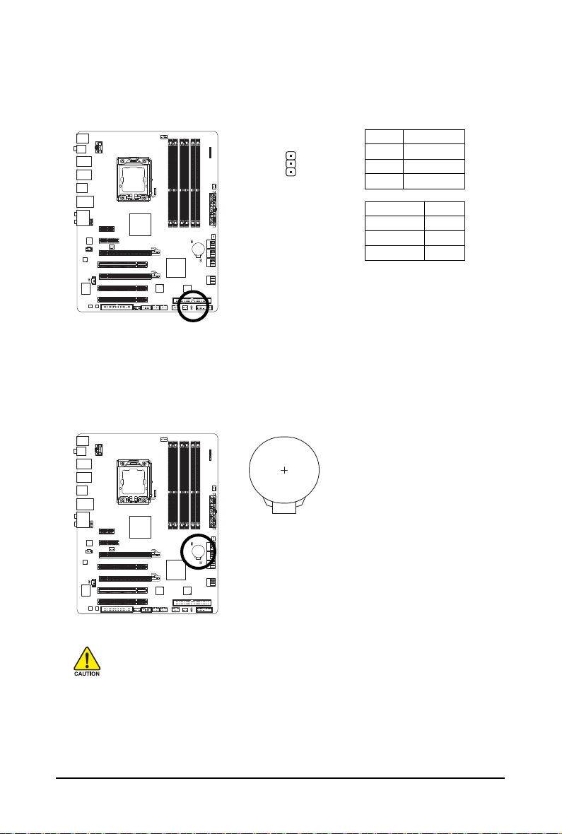
11) PWR_LED (System Power LED Header)
This header can be used to connect a system power LED on the chassis to indicate system power
status. The LED is on when the system is operating. The LED keeps blinking when the system is
in S1 sleep state. The LED is off when the system is in S3/S4 sleep state or powered off (S5).
Pin No. Definition
1 MPD+
2 MPD-
1
3 MPD-
System Status LED
S0 On
S1 Blinking
S3/S4/S5 Off
12) B ATTERY
The battery provides power to keep the values (such as BIOS configurations, date, and time
information) in the CMOS when the computer is turned off. Replace the battery when the battery
voltage drops to a low level, or the CMOS values may not be accurate or may be lost.
You may clear the CMOS values by removing the battery:
1. Turn off your computer and unplug the power cord.
2. Gently remove the battery from the battery holder and wait for one minute.
(Or use a metal object like a screwdriver to touch the positive and
negative terminals of the battery holder, making them short for 5 seconds.)
3. Replace the battery.
4. Plug in the power cord and restart your computer.
• Always turn off your computer and unplug the power cord before replacing the battery.
• Replace the battery with an equivalent one. Danger of explosion if the battery is replaced
with an incorrect model.
• Contact the place of purchase or local dealer if you are not able to replace the battery by
yourself or uncertain about the battery model.
• When installing the battery, note the orientation of the positive side (+) and the negative
side (-) of the battery (the positive side should face up).
• Used batteries must be handled in accordance with local environmental regulations.
Hardware Installation- 27 -
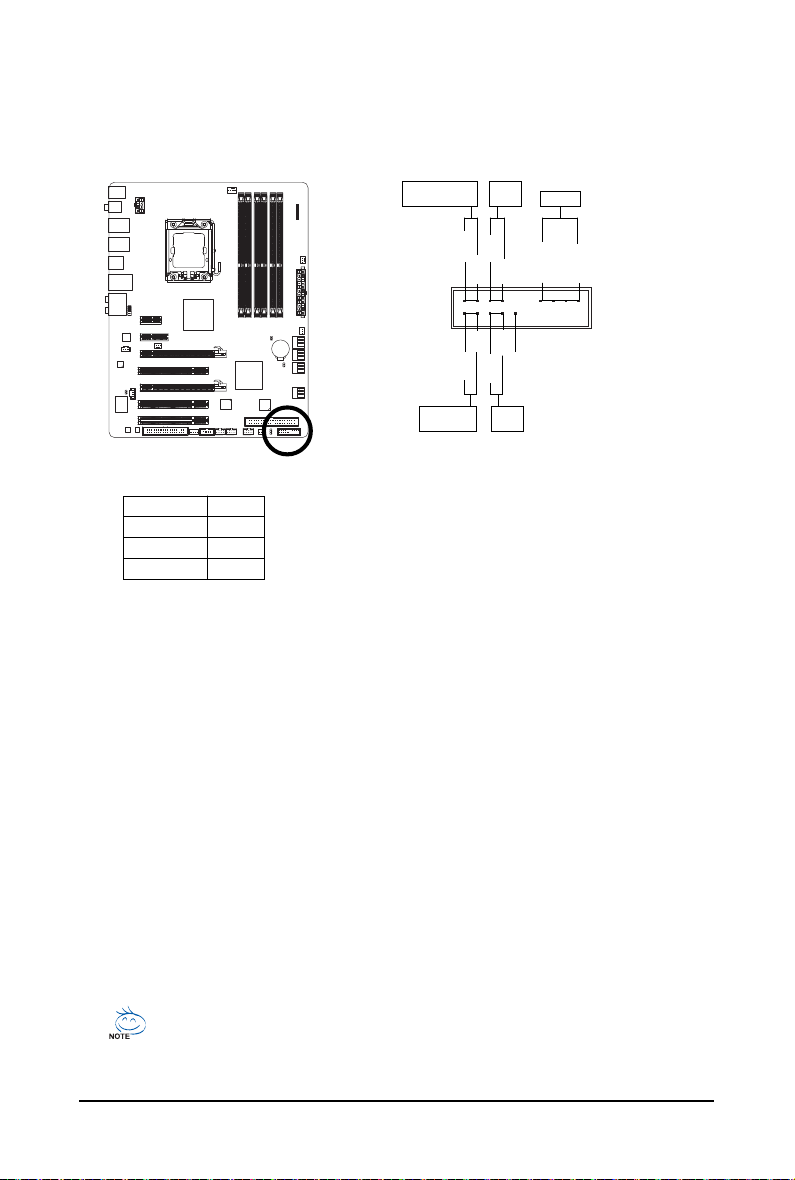
13) F_PANEL (Front Panel Header)
Connect the power switch, reset switch, speaker and system status indicator on the chassis front
panel to this header according to the pin assignments below. Note the positive and negative pins
before connecting the cables.
Message/Power/
Sleep LED
2
1
MSG+
HD+
MSG-
HD-
Power
Switch
PW+
RES-
PW-
RES+
Speaker
SPEAK-
SPEAK+
20
19
NC
Hard Drive
Activity LED
Reset
Switch
• MSG (Message/Power/Sleep LED, Yellow):
System Status LED
S0 On
S1 Blinking
S3/S4/S5 Off
Connects to the power status indicator on the chassis front panel . The
LED is on when the system is operating. The LED keeps blinking when
the system is in S1 sleep state. The LED is off when the system is in
S3/S4 sleep state or powered off (S5).
• PW (Power Switch, Red):
Connects to the power switch on the chassis front panel. You may configure the way to turn of f
your system using the power switch (refer to Chapter 2, "BIOS Setup," "Power Management
Setup," for more information).
• SPEAK (Speaker, Orange):
Connects to the speaker on the chassis front panel. The system reports system startup status
by issuing a beep code. One single short beep will be heard if no problem is detected at system
startup. If a problem is detected, the BIOS may issue beeps in different patterns to indicate the
problem. Refer to Chapter 5, "Troubleshooting," for information about beep codes.
• HD (Hard Drive Activity LED, Blue)
Connects to the hard drive activity LED on the chassis front panel. The LED is on when the hard
drive is reading or writing data.
• RES (Reset Switch, Green):
Connects to the reset switch on the chassis front panel. Press the reset switch to restart the
computer if the computer freezes and fails to perform a normal restart.
• NC (Purple):
No connection
The front panel design may differ by chassis. A front panel module mainly consists of
power switch, reset switch, power LED, hard drive activity LED, speaker and etc. When
connecting your chassis front panel module to this header, make sure the wire assignments and the pin assignments are matched correctly.
GA-EX58-UD4 Motherboard - 28 -
14) F_AUDIO (Front Panel Audio Header)
The front panel audio header supports Intel High Definition audio (HD) and AC'97 audio. You may
connect your chassis front panel audio module to this header. Make sure the wire assignments of
the module connector match the pin assignments of the motherboard header. Incorrect connection
between the module connector and the motherboard header will make the device unable to work
or even damage it.
For HD Front Panel Audio:
12
910
Pin No. Definition
1 MIC2_L
2 GND
3 MIC2_R
4 -ACZ_DET
5 LINE2_R
6 GND
7 FAUDIO_JD
8 No Pin
9 LINE2_L
10 GND
• The front panel audio header supports HD audio by default. If your chassis provides an
AC'97 front panel audio module, refer to the instructions on how to activate AC'97 functioninality
via the audio software in Chapter 5, "Configuring 2/4/5.1/7.1-Channel Audio."
• Audio signals will be present on both of the front and back panel audio connections
simultaneously. If you want to mute the back panel audio (only supported when using an HD
front panel audio module), refer to Chapter 5, "Configuring 2/4/5.1/7.1-Channel Audio."
• Some chassis provide a front panel audio module that has separated connectors on each
wire instead of a single plug. For information about connecting the front panel audio
module that has different wire assignments, please contact the chassis manufacturer.
For AC'97 Front Panel Audio:
Pin No. Definition
1 MIC
2 GND
3 MIC Power
4NC
5 Line Out (R)
6NC
7NC
8 No Pin
9 Line Out (L)
10 NC
15) CD_IN (CD In Connector, Black)
You may connect the audio cable that came with your optical drive to the header .
1
Pin No. Definition
1 CD-L
2 GND
3 GND
4 CD-R
Hardware Installation- 29 -
16) SPDIF_I (S/PDIF In Header, Red)
This header supports digital S/PDIF in and can connect to an audio device that supports digital
audio out via an optional S/PDIF in cable. For purchasing the optional S/PDIF in cable, please
contact the local dealer.
Pin No. Definition
1
1 Power
2 SPDIFI
3 GND
17) SPDIF_O (S/PDIF Out Header)
This header supports digital S/PDIF out and connects a S/PDIF digital audio cable (provided by
expansion cards) for digital audio output from your motherboard to certain expansion cards like
graphics cards and sound cards. For example, some graphics cards may require you to use a
S/PDIF digital audio cable for digital audio output from your motherboard to your graphics card if
you wish to connect an HDMI display to the graphics card and have digital audio output from the
HDMI display at the same time. For information about connecting the S/PDIF digital audio cable,
carefully read the manual for your expansion card.
GA-EX58-UD4 Motherboard - 30 -
1
Pin No. Definition
1 SPDIFO
2 GND
 Loading...