

Page 1

GA-8TRX330(-L)
Intel® Pentium® 4 Socket 478 Processor Motherboard
User's Manual
Rev. 1002
12ME-8TRX330L-1002
Page 2
Aug. 26, 2004
Motherboard
GA-8TRX330
Aug. 26, 2004
Motherboard
GA-8TRX330
Page 3

Copyright
© 2004 GIGA-BYTE TECHNOLOGY CO., LTD. All rights reserved.
The trademarks mentioned in the manual are legally registered to their respective companies.
Notice
The written content provided with this product is the property of Gigabyte.
No part of this manual may be reproduced, copied, translated, or transmitted in any form or by any
means without Gigabyte's prior written permission. Specifications and features are subject to
change without prior notice.
Product Manual Classification
In order to assist in the use of this product, Gigabyte has categorized the user manual in the
following:
n For quick installation, please refer to the "Hardware Installation Guide" included with the
product.
n For detailed product information and specifications, please carefully read the
"Product User Manual".
n For detailed information related to Gigabyte's unique features, please go to Gigabyte's
website under "Technology Guide" where information can be downloaded in .pdf format.
Fore more product details, please click onto Gigabyte's website at www.gigabyte.com.tw
Page 4

Table of Contents
GA-8TRX330(-L ) Motherboard Layout ...................................................................... 6
Block Diagram ........................................................................................................... 7
Chapter 1 Hardware Installation ................................................................................. 9
1-1 Considerations Prior to Installation ..................................................................... 9
1-2 Feature Summary ............................................................................................... 10
1-3 Installation of the CPU and Heatsink ................................................................ 12
1-3-1 Installation of the CPU ..................................................................................... 12
1-3-2 Installation of the Heatsink ...............................................................................13
1-4 Installation of Memory ........................................................................................ 14
1-5 Installation of Expansion Cards ......................................................................... 16
1-6 I/O Back Panel Introduction ............................................................................... 17
1-7 Connectors Introduction ..................................................................................... 18
Chapter 2 BIOS Setup ........................................................................................... 29
The Main Menu (For example: BIOS Ver. : E19) ........................................................ 30
2-1 Standard CMOS Features .................................................................................. 32
2-2 Advanced BIOS Features .................................................................................. 34
2-3 Integrated Peripherals ........................................................................................ 35
2-4 Power Management Setup................................................................................. 38
2-5 PnP/PCI Configurations ..................................................................................... 40
2-6 PC Health Status................................................................................................. 41
2-7 Frequency/Voltage Control ................................................................................ 42
2-8 Top Performance ................................................................................................. 43
2-9 Load Fail-Safe Defaults ...................................................................................... 44
2-10 Load Optimized Defaults .................................................................................... 44
2-11 Set Supervisor/User Password ......................................................................... 45
2-12 Save & Exit Setup ............................................................................................... 46
2-13 Exit Without Saving ............................................................................................. 46
- 4 -
Page 5

Chapter 3 Install Drivers ......................................................................................... 49
3-1 Install Chipset Drivers ........................................................................................ 49
3-2 Software Applications ......................................................................................... 50
3-3 Driver CD Information ......................................................................................... 50
3-4 Hardware Information ......................................................................................... 51
3-5 Contact Us ........................................................................................................... 51
Chapter 4 Appendix ............................................................................................... 53
4-1 Unique Software Utilities .................................................................................... 53
4-1-1 Xpress Recovery Introduction ..........................................................................53
4-1-2 Flash BIOS Method Introduction ......................................................................56
4-1-3 2 / 4 / 6 Channel Audio Function Introduction .................................................. 65
4-2 Troubleshooting................................................................................................... 71
- 5 -
Page 6
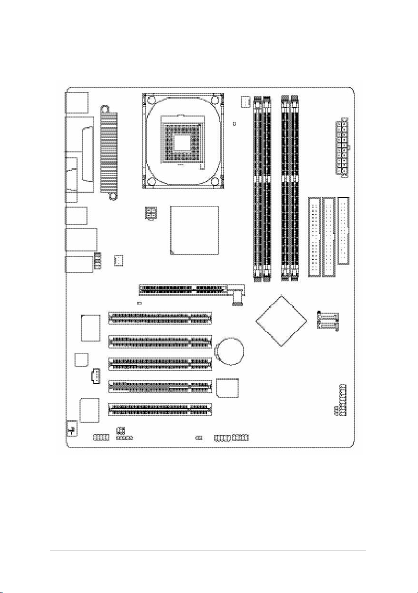
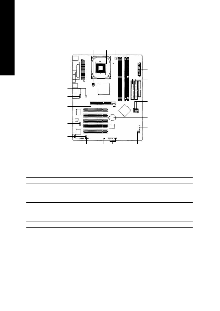
GA-8TRX330(-L ) Motherboard Layout
KB_MS
COMA
R_U SB
USB
AUDIO
CODEC
)
*
(
LPT
)
*
(
LAN
RT L
8100C (*
IT8712
F_AU DIO
)
CD_ IN
COM B
MOSHSINK
ATX_12 V
SYS_FAN
SPDIF_ IO
IR
2X_D ET
Soc ket 47 8
ATi R X330
CLR_ CM OS
PCI2
PCI3
PCI4
PCI5
AGP
PCI1
BIOS
F_U SB1
CPU _FAN
LED 1
BAT
GA-8TRX330
DDR3
DDR1
DDR2
ATi SB3 00
(IXP 300)
F_U SB2
DDR4
ATX
IDE2
S_ATA1
S_ATA2
PWR _LED
IDE1
FD D
F_PANEL
(*)
Only for GA-8TRX330-L.
- 6 -
Page 7
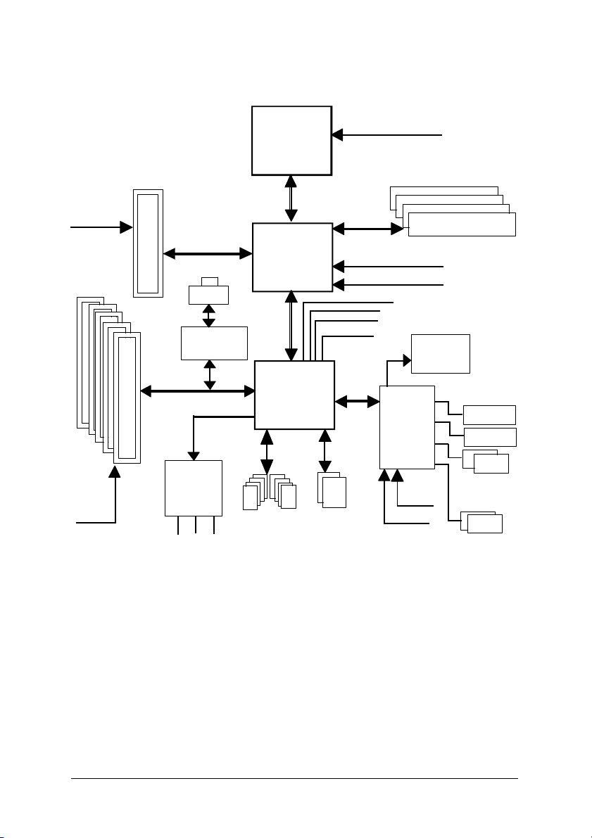
Block Diagram
AGPCLK
(66MHz)
5 PCI
PCICLK
(33MHz)
AGP 4X/8X
RJ45 (*
RTL8100 C (*
AC97 Link
AC97
CODEC
MIC
LINE-IN
)
)
LINE-OUT
Pentium 4
Socket 478
CPU
ATi RX330
ATi SB300
(IXP 300)
8 USB
Ports
CPUCLK+/- (100/133/200 MHz)
System Bus
400/533/800 M Hz
200/266/333/400 M Hz
HCLK+/- (100/133/200 MHz)
48 MHz
LPC BUS
ATA33/66/100/133
IDE Channels
ZCLK (66MHz)
66 MHz
33 MHz
14.318 MHz
IT8712
24 MHz
33 MHz
DDR
BIOS
Floppy
LPT Port
PS/2
KB/Mouse
COM
Ports
(*)
Only for GA-8TRX330-L.
- 7 -
Page 8

- 8 -
Page 9

Chapter 1 Hardware Installation
1-1 Considerations Prior to Installation
Preparing Your Computer
The motherboard contains numerous delicate electronic circuits and components which can
become damaged as a result of electrostatic discharge (ESD). Thus, prior to installation, please
follow the instructions below:
1. Please turn off the computer and unplug its power cord.
2. When handling the motherboard, avoid touching any metal leads or connectors.
3. It is best to wear an electrostatic discharge (ESD) cuff when handling electronic components
(CPU, RAM).
4. Prior to installing the electronic components, please have these items on top of an antistatic pad or
within a electrostatic shielding container.
5. Please verify that you the power supply is switched off before unplugging the power supply connector
from the motherboard.
Installation Notices
1. Prior to installation, please do not remove the stickers on the motherboard. These stickers are required
for warranty validation.
2. Prior to the installation of the motherboard or any hardware, please first carefully read the information
in the provided manual.
3. Before using the product, please verify that all cables and power connectors are connected.
4. To prevent damage to the motherboard, please do not allow screws to come in contact with the
motherboard circuit or its components.
5. Please make sure there are no leftover screws or metal components placed on the motherboard or
within the computer casing.
6. Please do not place the computer system on an uneven surface.
7. Turning on the computer power during the installation process can lead to damage to system
components as well as physical harm to the user.
8. If you are uncertain about any installation steps or have a problem related to the use of the product,
please consult a certified computer technician.
English
Instances of Non-Warranty
1. Damage due to natural disaster, accident or human cause.
2. Damage as a result of violating the conditions recommended in the user manual.
3. Damage due to improper installation.
4. Damage due to use of uncertified components.
5. Damage due to use exceeding the permitted parameters.
6. Product determined to be an unofficial Gigabyte product.
Hardware Installation- 9 -
Page 10

English
1-2 Feature Summary
CPU w Supports the latest Intel® Pentium® 4 Socket 478 CPU
w Supports 800/533/400MHz FSB
w L2 cache var ies with CPU
Chipset w North Bridge: ATi RX330
w South Bridge: ATi SB300(IXP 300)
Memory w 4 DDR DIMM memory slots (supports up to 4GB memory)
w Supports 2.5V DDR DIMM
w Supports dual channel DDR 400/333/266/200 DIMM
Slots w 5 PCI slots
w 1 A GP slot
IDE Connections w 2 IDE connection (UDMA 33/ATA 66/ATA 100/ATA 133), allows connection of 4
IDE devices
FDD Connections w 1 FDD connection, allows connection of 2 FDD devices
Onboard SATA w 2 Serial ATA connections
Peripherals w 1 parallel port supporting Normal/EPP/ECP mode
w 1 Serial port (COMA), onboard COMB connection
w 8 USB 2.0/1.1 ports (rear x 4, front x 4 via cable)
w 1 front audio connector
w 1 IR connector
w 1 PS/2 keyboard port
w 1 PS/2 mouse port
Onboard LAN(*
)
w Onboard RTL8100C Chipset (10/100 Mbit)
w 1 RJ 45 port
Onboard Audio w Realtek ALC655 CODEC
w Support Jack-Sensing
w Supports 2 / 4 / 6 channel audio
w Line Out / 2 front speaker
w Line In / 2 rear speaker(by s/w switch)
w Mic In / center& subwoofer(by s/w switch)
w Supports SPDIF In/Out connection
w CD In
(Note 1)
(Note 2)
(Note 1) Due to standard PC architecture, a certain amount of memory is reserved for system usage and
therefore the actual memory size is less than the stated amount.
For example, 4 GB of memory size will instead be shown as 3.xxGB memory during system startup.
(Note 2) Due to chipset limitation, the total number of memory chips of memory module(s) installed in the
same channel cannot be more than eight, otherwise DDR400 mem ory will slow down to DDR333.
For the latest information about mem ory modules supported on this motherboard, please go to
GIGABYTE's website.
(*)
Only for GA-8TRX330-L.
GA-8TRX330(-L) M otherboard - 10 -
Page 11

I/O Control w IT8712
Hardware Monitor w System voltage detection
w CPU temperature detection
w CPU / System fan speed detection
w CPU warning temperature
w CPU / System fan failure warning
BIOS w Use of licensed AWARD BIOS
w Supports Q-Flash
Additional Features w Supports @BIOS
w Supports EasyTune
Overclocking w Over Clock via BIOS (CPU)
Form Factor w ATX form factor; 30.5cm x 24.4cm
English
Hardware Installation- 11 -
Page 12
English
1-3 Installation of the CPU and Heatsink
Before installing the CPU, plea se comply with the following conditions:
1. Please make su re that the motherboard supports the CPU.
2. Please take note of the one indented corner of the CPU. If you install the CPU in the wrong
direction, the CPU will not insert properly. If this occurs, please change the insert direction
of the CPU.
3. Please add an even layer of heat sink paste between the CPU and heatsink.
4. Please m ake sure the heatsink is installed on the CPU prior to system use, otherwise
overheating and permanent damage of the CPU may occur.
5. Please set the CPU host frequency in accordance with the processor specifications. It is not
recomm ended that the system bus frequency be set beyond hardware specifications since it
does not meet the required standards for the peripherals. If you wish to set the frequency
beyond the proper specifications, please do so according to your hardware specifications
including the CPU, graphics card, memory, hard drive, etc.
HT functionality r equirement content :
Enabling the functionality of Hyper-Threading Technology for your comp uter system requires all
of the following platform com ponents:
- CPU: An Intel® Pentium 4 Processor with HT Tec hnology
- Chipset: An ATi Chipset that supports HT Technology
- BIOS: A BIOS that supports HT Tech nology and has it enabled
- OS: An operation system that has optimizations for HT Technology
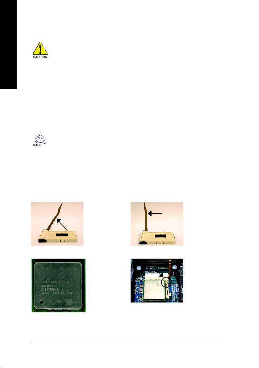
1-3-1 Installation of the CPU
Fig. 1
Angling the
rod to 65
GA-8TRX330(-L) M otherboard - 12 -
Pin1 indicator
Angling the rod to 65-
0
degree maybe feel a
kind of tight , and then
continue pull the rod to
90 -d egree when a
"click" noise is heard.
Fig. 3
CPU Top View
Pin1 indicator
Socket
Actuation
Lever
Fig. 2
Pull the rod to the
90-degree directly.
Fig. 4
Locate Pin 1 in the
socket and look
for a (golden) cut edge
on the CPU
upper corner. Then
insert the CPU
into the socket.
Page 13
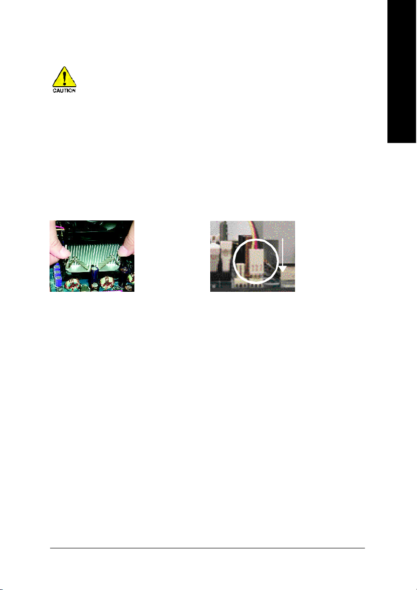
1-3-2 Installation of the Heatsink
Before installing the CPU cool fan , adhere to the following warning:
1. Please use Intel approved cooling fan.
2. We recommend you to apply the thermal tape to provide better heat conduction
between your CPU and cooling fan.
(The CPU cooling fan might stick to the CPU due to the hardening of the
thermal paste. During this condition if you try to remove the cooling fan, you
might pull the processor out of the CPU socket alone with the cooling fan, and
might damage the processor. To avoid this from happening, we suggest you to
either use thermal tape instead of therm al paste, or rem ove the cooling fan with
extreme caution.)
3. Make su re the CPU fan power cable is plugged in to the CPU fan connector, this
completes the installation. Please refer to CPU cooling fan user's manual for
more detail installation procedure.
English
Fig.1
Fasten the cooling fan
supporting-base onto
the CPU socket on the
motherboard.
Fig. 2
Make sure the CPU fan
is plugged to the CPU
fan connector, than
install com plete.
Hardware Installation- 13 -
Page 14
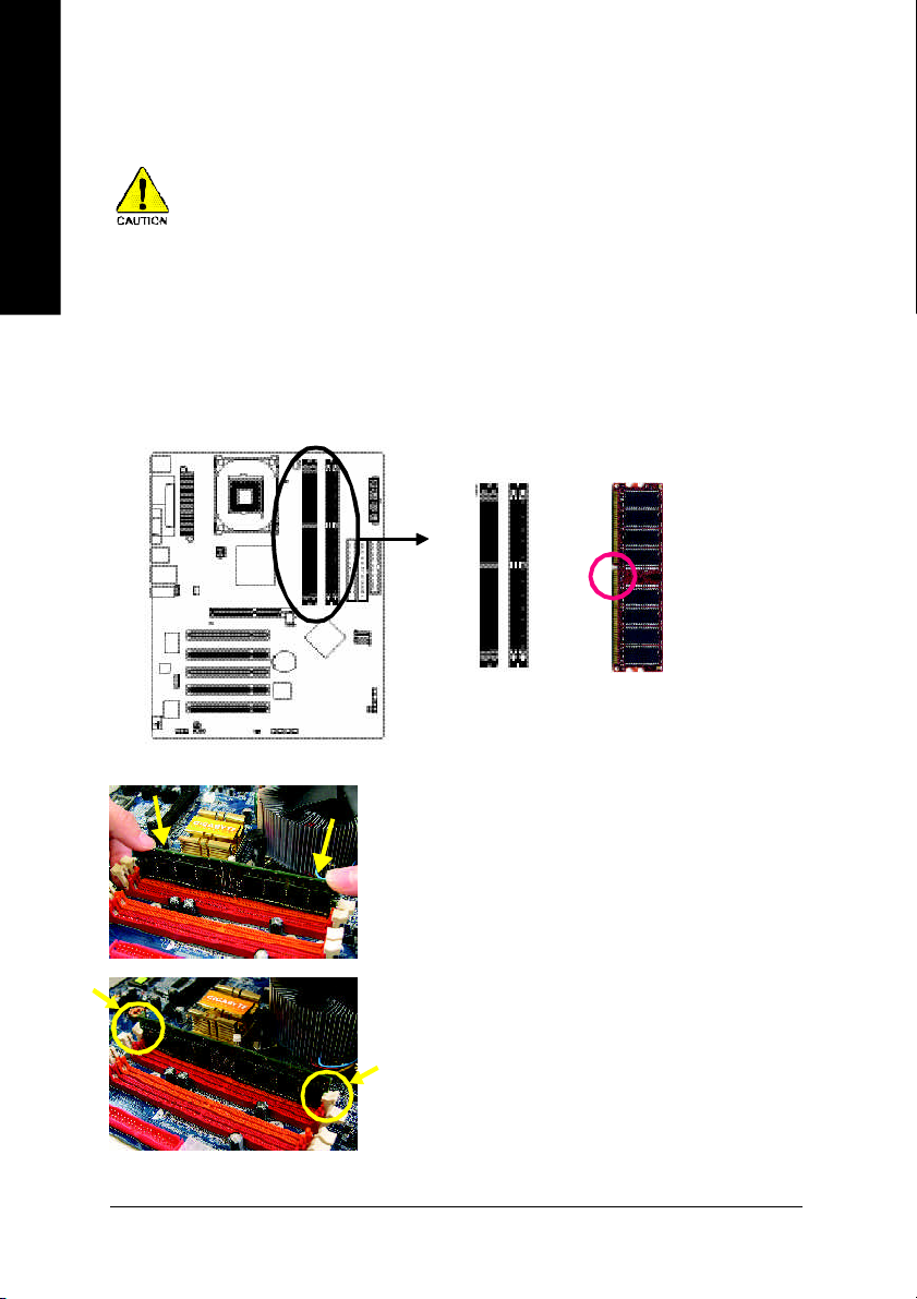
1-4 Installation of Memory
English
Bef ore ins talli ng the memory mod ules , ple ase comply wit h t he fol lowin g cond itions:
1 . Ple ase mak e sure t hat t he memo ry used is suppor ted by the mothe rboa rd. It is recommend ed that
mem ory of simi lar cap aci ty, s pec ifica tion s and brand b e u sed.
2 . Befo re i nstall ing or r emovin g me mory modul es, pl ease make sure tha t th e comp uter power is swit ched
of f t o prev ent hardw are da mage .
3 . Mem ory mod ules hav e a fo olpr oof inserti on des ign. A me mory mo dule can be ins talled in only one
dir ectio n. If you are unable to i nsert t he modul e, ple ase switc h the dire ction .
The motherboard supports DDR mem ory modules, whereby BIOS will automatically detect mem ory
capacity and specifications. Mem ory modules are designed so that they can be inserted only in one direction.
The memor y capacity used can differ with each slot.
Notch
DDR
Fig.1
The DIMM socket has a notch, so the DIMM m emory module
can only fit in one direction. Insert the DIM M mem ory module
vertically into the DIMM socket. Then push it down.
Fig.2
Close the plastic clip a t both edges of the DIMM sock ets to
lock the DIMM module.
Reverse the installation steps when you wish to remov e the
DIMM module.
GA-8TRX330(-L) M otherboard - 14 -
Page 15

Dual Channel DDR
GA-8TRX330(-L) supports the Dual Channel Technology. After operating the Dual Channel Technology, the
bandwidth of Memory Bus will add double.
GA-8TRX330(-L) includes 4 DIMM sockets, and each Channel has two DIMM sockets as following:
Channel A : DDR 1, DDR 2
Channel B : DDR 3, DDR 4
If you want to operate the Dual Channel Technology, please note the following explanations due
to the lim itation of Intel chipset speci fications.
1. One/three DDR memory module is installed: The Dual Channel Technology can't operate
when only one DDR mem ory module is installed.
2. Two DDR mem ory modules are installed (the same mem ory size and type): The Dual
Channel Technol ogy will operate when two mem ory modules are inserted individually into
Channel A and B. If you install two memory m odules in the same channel, the Dual Channel
Technology will not operate.
3. Four DDR mem ory modules are installed: If you install four mem ory modules at the same
time, the Dual Channel Technology will operate only when those modules have the same
mem ory size and type.
We'll strongly recomm end our user to slot two DDR mem ory modules into the DIMM s with the same color in
order for Dual Channel Technology to work.
The following table is for Dual Channel Technology combin ation: (DS: Double Side, SS: Single Side)
DDR 1 DDR 2 DDR 3 DDR 4
2 mem ory modules
4 mem ory modules
DS/SS X DS/SS X
X DS/SS X DS/SS
DS/SS DS/SS DS/SS DS/SS
English
Hardware Installation- 15 -
Page 16
English
1-5 Installation of Expansion Cards
You can install your expansion card by following the steps outlined below:
1. Read the related expansion card's instruction docum ent before install the expansion card into the
computer.
2. Rem ove your computer's chassis cover, screws and slot bracket from the computer.
3. Press the expansion card firmly into expansion slot in motherboard.
4. Be sure the metal contacts on the card are indee d seated in the slot.
5. Replace the screw to secure the slot bracket of the expansion card.
6. Replace your computer's chassis cover.
7. Power on the computer, if necessary, setup BIOS utility of expansion card from BIOS.
8. Install related driver from the operating system.
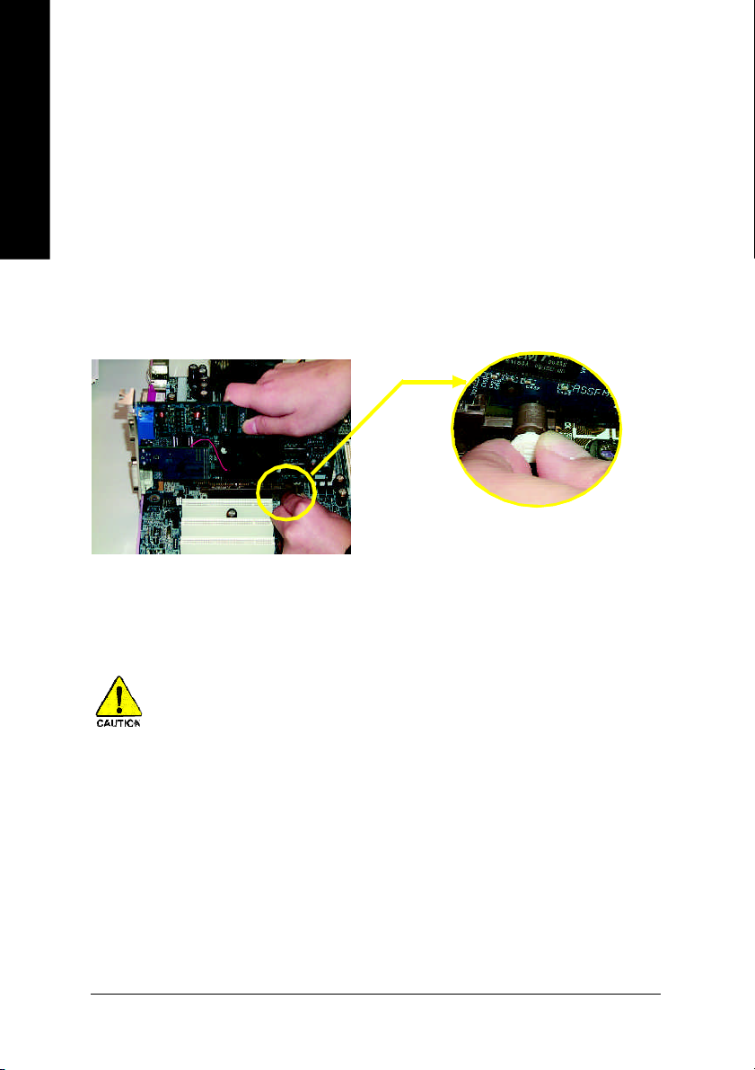
Installing a AGP expansion card:
Please carefully pull out the small white- drawable
bar at the end of the AGP slot when you try to install/
AGP Card
Uninstall the AGP card. Please align the AG P card to
the onboard AGP slot and press firm ly down on the
slot .Make sure your AGP card is locked by the small
white- drawable bar.
When an AGP 2x (3.3V) car d is installed the 2X_DET will light up, indicating a non-suppo rted
graphics card is inserted. Informing users that system might not boot up normally due to AGP 2x
(3.3V) is not supported by the chipset.
GA-8TRX330(-L) M otherboard - 16 -
Page 17
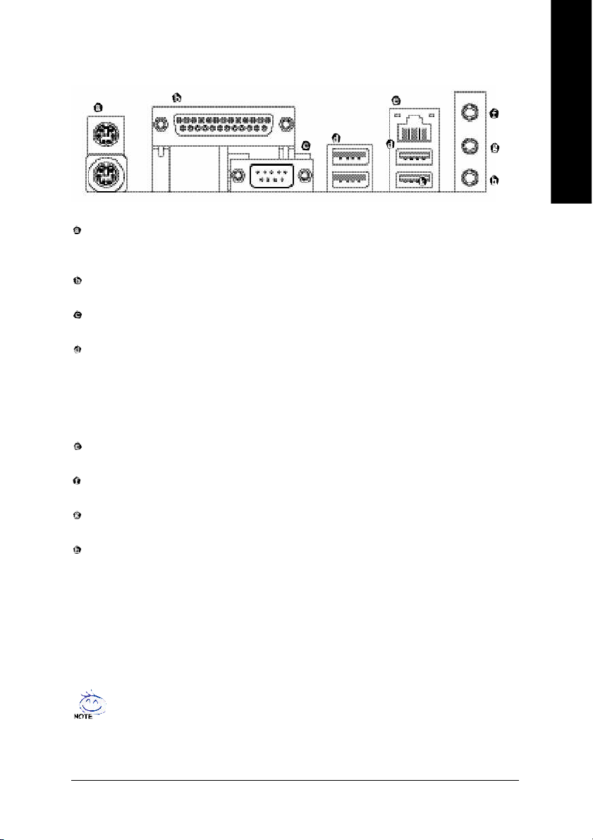
1-6 I/O Back Panel Introduction
(*)
PS/2 Keyboard and PS/2 Mouse Connector
To install a PS/2 port keyboard and mouse, plug the mouse to the upper port (green) and the keyboard to the
lower port (purple).
Parallel Port
The parallel port allows connection of a printer, scanner and other peripheral devices.
COM A (Serial Port)
Connects to serial-based mouse or data processing devices.
USB port
Before you connect your device(s) into USB connector(s), please make sure your device(s) such as
USB keyboard, mouse, scanner, zip, speaker...etc. have a standard USB interface. Also make sure
your OS supports USB controller. If your OS does not support USB controller, please contact OS ven
dor for possible patch or driver upgrade. For more information please contact your OS or device(s)
vendors.
LAN Port (*
The provided Internet connection is fast Ethernet, providing data transfer speeds of 10/100Mbps.
Line In
Devices like CD-ROM, walkman etc. can be connected to Line In jack.
Line Out
Connect the stereo speakers, earphone or front surround channels to this connector.
MIC In
Microphone can be connected to MIC In jack.
)
English
You can use audio software to configure 2-/4-/6-channel audio functioning.
(*)
Only for GA-8TRX330-L.
Hardware Installation- 17 -
Page 18
1-7 Connectors Introduction
English
4
12
9
13
14
1) ATX_12V
2) ATX (Power Connector)
3) CPU_FAN
4) SYS_FAN
5) FDD
6) IDE1/IDE2
7) S_ATA1 / S_ATA2
8) LED1
9) 2X_DET
10) PWR_LED
1 3
17
8
16
18
11) F_PANEL
12) F_AUDIO
13) CD_IN
14) SPDIF_IO
15) COMB
16) F_USB1 / F_USB2
17) IR
18) CLR_CMOS
19) BAT
2
6
5
7
4
19
11
1015
GA-8TRX330(-L) M otherboard - 18 -
Page 19
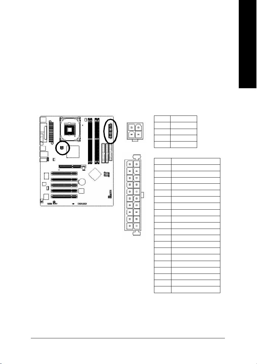
1/2) ATX_12V/ATX (Power Connector)
With the use of the power connector, the power supply can supply enough stable power to all the
components on the motherboard. Before connecting the power connector, please make sure that all
components and devices are properly installed. Align the power connector with its proper location on
the mo therboard and connect tightly.
The ATX_12V power connector mainly supplies po wer to the CPU. If the ATX_12V power
connector is not connected, the system will not start.
Caution!
Please use a power supply that is able to handle the system voltage requirements. It is
recomm ended that a power supply that can withstand high power consumption be used (300W or
greater). If a power supply is used that does not provide the required power, the result can lead to an
unstable system or a system that is unable to start.
Pin No. Definition
2
4
1 0
1
2 0
11
1 GND
1
2 GND
3
3 +12V
4 +12V
Pin No. Definition
1 3.3V
2 3.3V
3 GND
4 VCC
5 GND
6 VCC
7 GND
8 Power Good
9 5V SB(stand by +5V)
10 +12V
11 3.3V
12 -12V
13 GND
14 PS_ON(softOn/Off)
15 GND
16 GND
17 GND
18 -5V
19 VCC
20 VCC
English
Hardware Installation- 19 -
Page 20
English
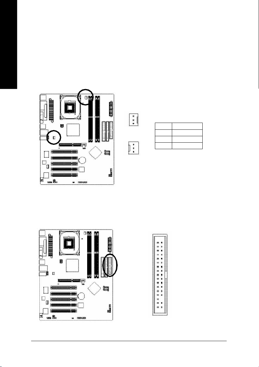
3/4) CPU_FAN / SYS_FAN (Cooler Fan Power Connector)
The cooler fan power connector supplies a +12V power voltage via a 3-pin power connector and
possesses a foolproof connection design.
Most coolers are designed with color-coded power connector wires. A red power connector wire
indicates a positive connection and requires a +12V power voltage. The black connector wire is
the ground wire (GND).
Please remem ber to connect the power to the cooler to prevent system overheating and failure.
Caution!
Please rem ember to connect the power to the CPU fan to prevent CPU overheating and failure.
1
1
Pin No. Definition
1 GND
2 +12V
3 Sense
CPU_FAN
SYS_FAN
5) FDD (Floppy Connector)
The FDD connector is used to connect the FDD cable while the other end of the cable connects to the
FDD drive. The types of FDD drives supported are: 360KB, 720KB, 1.2MB, 1.44MB and 2.88MB.
Please connect the red power connector wire to the pin1 position.
GA-8TRX330(-L) M otherboard - 20 -
3 4
2
3 3
1
Page 21
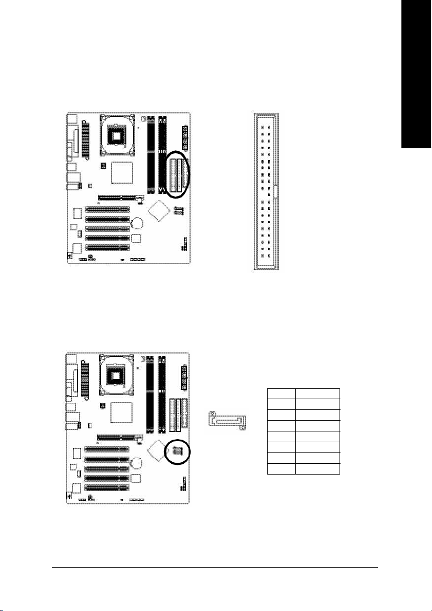
6) IDE1/IDE2 (IDE Connector)
An IDE device connects to the computer via an IDE connector. One IDE connector can connect to one
IDE cable, and the single IDE cable can then connect to two IDE devices (hard drive or optical drive).
If you wish to connect two IDE devices, please set the jumper on one IDE device as Master and the
other as Slave (for information on settings, please refer to the instructions located on the IDE device).
3 94 0
English
2
1
7) S_ATA1/S_ATA2 (Serial ATA Connector)
Serial ATA can provide 150M B/s transfer rate. Please refer to the BIOS setting for the Serial ATA
and install the proper driver in order to work properly.
Pin No. Definition
1 GND
1
7
2 TXP
3 TXN
4 GND
5 RXN
6 RXP
7 GND
Hardware Installation- 21 -
Page 22
English
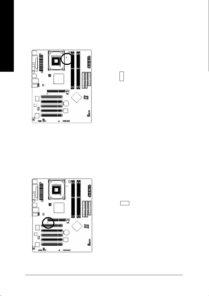
8) LED1
Do not remove mem ory modules while DIMM LED is on. It might cause short or other unexpected
damages due to the 2.5V stand by voltage. Rem ove mem ory modules only when AC Power cord is
disconnected.
+
-
9) 2X_DET
When an AGP 2X (3.3V) card is installed the 2X_DET will light up, indicating a nonsupported graphics
card is inserted. Informing users that system m ight not boot up normal ly due to AGP 2X (3.3V) is not
supported by the chipset.
GA-8TRX330(-L) M otherboard - 22 -
-
+
Page 23
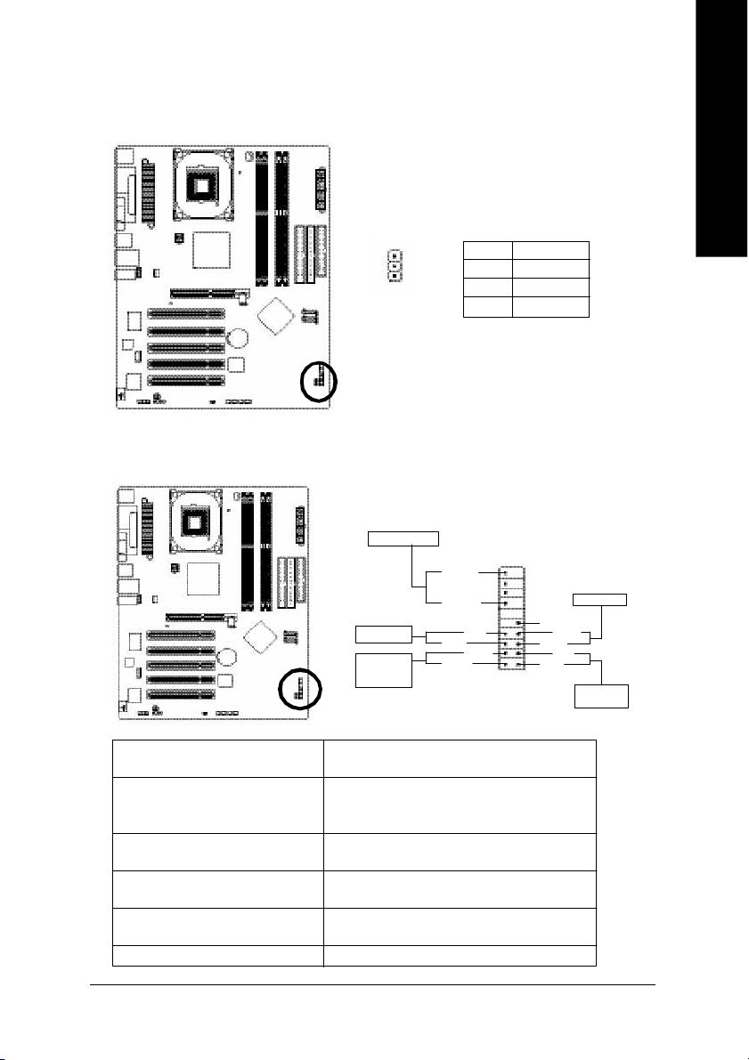
10) PWR_LED
PWR_LED is connect with the system power indicator to indicate whether the system is on/off. It will
blink when the system enters suspend mode.
Pin No. Definition
1
1 MPD+
2 MPD3 MPD-
11) F_PANEL (Front Panel Jumper)
Please connect the power LED, PC peaker, reset switch and power switch etc of your chassis front
panel to the F_PANEL connector according to the pin assignment below.
Speaker Connec tor
1 9
Power Swit ch
Message LED/
Powe r/
Sleep L ED
SPEAK-
SPEAK+
PW+
MSG+
PW-
MSG-
2 0
Reset Swit ch
NC
RES+
RES-
HD -
HD+
1
2
IDE H ard Disk
English
Acti ve L ED
HD (IDE Hard Disk Active LED) Pin 1: LED anode(+)
(Blue) Pin 2: LED cathode(-)
SPEAK ( Speaker Connector) Pin 1: VCC(+)
(Amber) Pin 2- Pin 3: NC
Pin 4: Data(-)
RES (Reset Switch) Open: Normal Operation
(Green) Close: Reset Hardware System
PW (Power Switch) Open: Normal Operation
(Red) Close: Power On/Off
MSG(M essage LED/Power/Sleep LED) Pin 1: LED anode(+)
(Yellow) Pin 2: LED cathode(-)
NC( Purple) NC
Hardware Installation- 23 -
Page 24
English
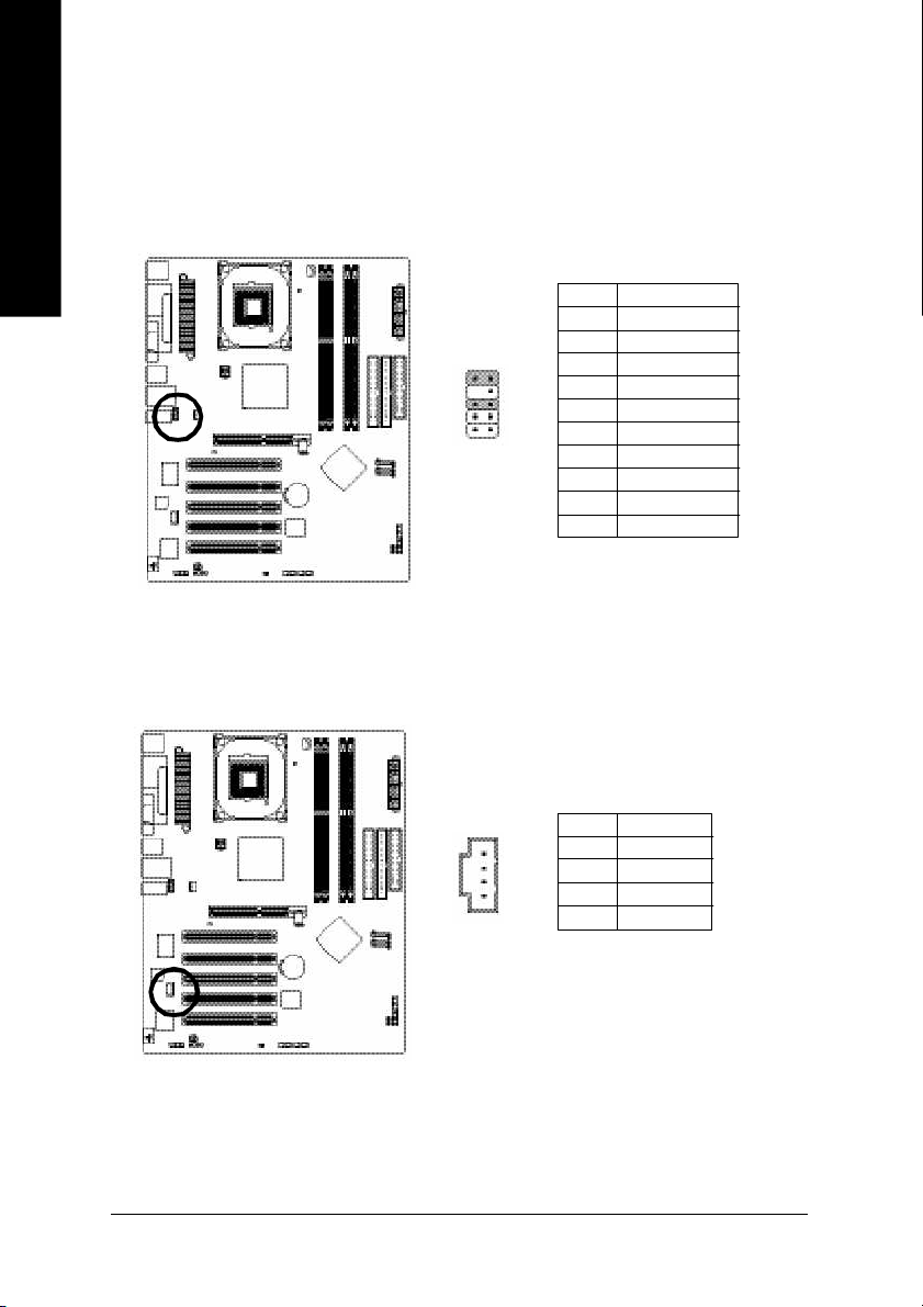
12) F_AUDIO (Front Audio Connector)
If you want to use Front Audio connector, you must remove 5-6, 9-10 Jumper. In order to utilize the
front audio header, your chassis must have front audio connector. Also please make sure the pin
assigment on the cable is the same as the pin assigm ent on the MB header. To find out if the chassis
you are buying support front audio connector, please contact your dealer.Please note, you can have the
alternative of using front audio connector or of using rear audio connector to play sound.
Pin No. Definition
1 MIC
2 GND
1 0
9
2
1
3 MIC_BIAS
4 POWER
5 FrontAudio(R)
6 RearAudio(R)
7 Reserved
8 No Pin
9 FrontAudio (L)
10 RearAudio(L)
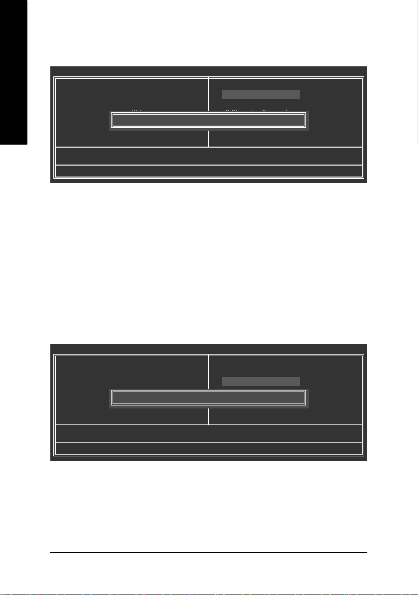
13) CD_IN (CD IN)
Connect CD-ROM or DVD-ROM audio out to the connector.
GA-8TRX330(-L) M otherboard - 24 -
Pin No. Definition
1
1 CD-L
2 GND
3 GND
4 CD-R
Page 25

14) SPDIF_IO (SPDIF In/Out)
The SPDIF output is capable of providing digital audio to external speakers or compressed AC3 data to
an external Dolby Digital Decoder. Use this feature only when your stereo system has digital input
function. Use SPDIF IN feature only when your device has dig ital output function.
Be careful with the polarity of the SPDIF_IO connector. Check the pin assignm ent carefully while you
connect the SPDIF cable, incorrect connection between the cable and connector will make the
device unable to work or even damage it. For optional SPDIF cable, please contact your local
dealer.
Pin No. Definition
6
5
1 VCC
2 No Pin
3 SPDIF
4 SPDIFI
5 GND
6 GND
2
1
15) COMB (COM B Connector)
Be careful with the polarity of the COM connector. Check the pin assignment carefully while you
connect the COM cable, incorrect connection between the cable and connector will make the
device unable to work or even damage it. For optional COM cable, please contact your local dealer.
English
2 1 0
1 9
Pin No. Definition
1 NDCD B-
2 NSIN B
3 NSOUT B
4 NDTR B-
5 GND
6 NDSR B-
7 NRTS B-
8 NCTS B9 NRI B-
10 No Pin
Hardware Installation- 25 -
Page 26

English
16) F_ USB1 / F_USB2 (Front USB Connector)
Be careful with the polarity of the front USB connector. Check the pin assignment carefully while
you connect the front USB cable, incorrect connection between the cable and connector will make
the device unable to work or even damag e it. For optional front USB cable, please contact your
local dealer. The "USB Device Wake up From S3" is only supported by rear USB ports.
Pin No. Definition
1 Power
2 Power
9
3 USB DX-
4 USB Dy-
5 USB DX+
6 USB Dy+
7 GND
8 GND
9 No Pin
10 NC
2
1 0
1
17) IR
Be careful with the polarity of the IR connector while you connect the IR. Please contact your
nearest dealer for optional IR device.
1
GA-8TRX330(-L) M otherboard - 26 -
Pin No. Definition
1 VCC
2 No Pin
3 IR RX
4 GND
5 IR TX
Page 27

18) CLR_CMOS (Clear CMOS)
You may clear the CMOS data to its default values by this jumper. To clear CM OS, temporarily
short 1-2 pin. Default doesn't include the "Shunter" to prevent from improper use this jumper.
1
Open: Norm al
1
Short: Clear CMOS
19) BAT(Battery)
English
Danger of explosion if battery is incorrectly replaced.
Replace only with the same or equivalent type
recom mended by the manufacturer.
Dispose of used batteries ac cording to the manufacturer's
instructions.
If you want to erase CMOS...
1.Turn OFF the computer and unplug the power cord.
2.Remo ve the battery, wait for 30 sec ond.
3.Re-install the battery.
4.Plug the power cord and turn ON the com puter.
Hardware Installation- 27 -
Page 28

English
GA-8TRX330(-L) M otherboard - 28 -
Page 29

Chapter 2 BIOS Setup
BIOS (Basic Input and Output System) includes a CMOS SETUP utility which allows user to configure
required settings or to activate certain system features.
The CMOS SETUP sav es the configuration in the CMOS SRAM of the motherboard.
When the pow er is turned off, the battery on the motherboard supplies the necessary power to the CMOS
SRAM.
When the pow er is turned on, pushing the <Del> button during the BIOS POST (Power-On Self Test) w ill
take you to the CMOS SETUP screen. You can enter the BIOS setup screen by pressing "Ctrl + F1".
When setting up BIOS for the first time, it is recommended that y ou save the current BIOS to a disk in the
event that BIOS needs to be reset to its original settings. If you wish to upgrade to a new BIOS, either
Gigabyte's Q-Flash or @BIOS utility can be used.
Q-Flash allows the user to quickly and easily update or backup BIOS without entering the operating system.
@BIOS is a Window s-based utility that does not require users to boot to DOS before u pgrading BIOS but
directly download and update BIOS from the Internet.
CONTROL KEYS
< >< >< >< > Move to select item
<Enter> Select Item
<Esc> Main Menu - Quit and not save changes into CMOS Status Page Setup Menu
and Option Page Setup Menu - Exit current page and return to Main Menu
<Page Up> Increase the numeric value or make changes
<Page Down> Decrease the numeric v alue or make changes
<F1> General help, only for Status Page Setup Menu and Option Page Setup Menu
<F2> Item Help
<F5> Restore the previous CMOS value from CMOS, only for Option Page Setup Menu
<F6> Load the file-safe default CMOS v alue from BIOS default table
<F7> Load the Optimized Defaults
<F8> Q-Flash utility
<F9> System Information
<F10> Save all the CMOS changes, only for Main Menu
English
Main Menu
The on-line description of the highlighted setup function is displayed at the bottom of the screen.
Status Page Setup Menu / Option P age Setup Menu
Press F1 to pop up a small help window that describes the appropriate keys to use and the possible selections for the highlighted item. To exit the Help Window press <Esc>.
BIOS Setup- 29 -
Page 30

English
The Main Menu (For example: BIOS Ver. : E19)
Once y ou enter Award BIOS CMOS Setup Utility, the Main Menu (as figure below ) w ill appear on the screen.
Use arrow keys to select among the items and press <Enter> to accept or enter the sub-menu.
CMOS Setup Utility-Copy right (C) 1984-2004 Award S oftware
} Standard CMOS Features
} Advanc ed BIOS Features
} Integrated Peripherals
} Power Management Setup
} PnP /PCI Configurations
} PC Health St atus
} Frequency /Voltage Control
ESC: Quit higf: Selec t Item
F8:Q-Flash F10: Save & Exit S etup
Time, Date, Hard Disk Ty pe...
If y ou can't find the setting you want, please press "Ctrl+F1" to search the advanced option hidden.
n Standard CMOS Features
This setup page includes all the items in standard compatible BIOS.
n Advanced BIOS Feat ures
This setup page includes all the items of Award special enhanced features.
n Integrated Peripherals
This setup page includes all onboard peripherals.
n Power Management Setup
This setup page includes all the items of Green function features.
n PnP/PCI Con figuration
This setup page includes all the configurations of PCI & PnP ISA resources.
n PC Health Status
This setup page is the System auto detect Temperature, voltage, fan, speed.
n Frequency/Voltage Control
This setup page is control CPU's clock and frequency ratio.
n Top Performance
If y ou wish to maximize the performance of y our system, set "Top Performance" as "Enabled".
n Load Fail-Safe Defau lts
Fail-Safe Defaults indicates the value of the system parameters which the system would be in safe
configuration.
Top P erform ance
Load Fail-Safe Defaults
Load Optimized Defaults
Set Supervisor Password
Set User Password
Save & Exit Setup
Exit Without Saving
GA-8TRX330(-L) Motherboard - 30 -
Page 31

n Load Optimized Defaults
Optimized Defaults indicates the value of the sy stem parameters which the system w ould be in best
performance c onfiguration.
n Set Su perv isor Password
Change, set, or disable password. It allows you to limit access to the sy stem and Setup, or just to Setup.
n Set User Password
Change, set, or disable passw ord. It allows you to limit access to the system.
n Save & Exit Setup
Save CMOS value settings to CMOS and exit setup.
n Exit Without Saving
Abandon all CMOS value changes and exit setup.
English
BIOS Setup- 31 -
Page 32

English
2-1 Standard CMOS Features
CMOS Setup Utility-Copy right (C) 1984-2004 Award S oftware
Date (mm:dd:y y) Mon, May 3 2004
Time (hh:mm:ss) 22:31:24
} IDE Prim ary Master [None]
} IDE Primary Slave [None]
} IDE Secondary Master [None]
} IDE Secondary Slave [None]
Drive A [1.44M, 3.5"]
Drive B [None]
Holt On [All, But Keyboard]
Base Memory 640K
Extended Mem ory 255M
Total Memory 256M
higf: Move Enter: Select +/-/PU/P D: Value F10: Save ESC: Ex it F1: Gene ral Help
F5: Previous Values F6: Fail-Save Default F7: Optimized De faults
Date
The date format is <week>, <month>, <day>, <y ear>.
Week The week, from Sun to Sat, determined by the BIOS and is display only
Month The month, Jan. Through Dec.
Day The day, from 1 to 31 (or the maximum allowed in the month)
Year The year, from 1999 through 2098
Time
The times format in <hour> <minute> <second>. The time is calculated base on the 24-hour
military-time clock. For example, 1 p.m. is 13:00:00.
IDE Primary Master, Slave / IDE Secondary Master, Slave
IDE HDD Auto-Detection Press "Enter" to select this option for automatic device detection.
IDE Channel 0 Master(Slave) IDE Device Setup. You can use one of three methods:
Auto Allows BIOS to automatically detect IDE devices during POST(default)
None Select this if no IDE devices are used and the system will skip the automatic
detection step and allow for faster system start up.
Manual User can manually input the correct settings
Access Mode Use this to set the access mode for the hard drive. The four options are:
CHS/LBA/Large/Auto(default:Auto)
Hard drive information should be labeled on the outside drive casing. Enter the appropriate option
based on this information.
Cylinder Number of cylinders
Head Number of heads
Precomp Write precomp
Landing Zone Landing zone
Sector Number of sectors
If a hard disk has not been installed, select NONE and press <Enter>.
Standard CMOS Features
Item Help
Menu Level}
Change the day, month,
year
<Week>
Sun. to Sa t.
<Month>
Jan. to Dec.
<Day>
1 to 31 (or maximum
allowe d in the m onth)
<Year>
1999 to 2098
GA-8TRX330(-L) Motherboard - 32 -
Page 33

Drive A / Drive B
The category identifies the ty pes of floppy disk drive A or drive B that has been installed in the computer.
None No floppy drive installed
360K, 5.25" 5.25 inch PC-type standard drive; 360K byte capacity.
1.2M, 5.25" 5.25 inch AT-ty pe high-density drive; 1.2M byte capacity
(3.5 inch w hen 3 Mode is Enabled).
720K, 3.5" 3.5 inch double-sided driv e; 720K byte capacity
1.44M, 3.5" 3.5 inch double-sided driv e; 1.44M byte capacity .
2.88M, 3.5" 3.5 inch double-sided driv e; 2.88M byte capacity .
Halt on
The category determines whether the computer will stop if an error is detected during power up.
No Errors The sy stem boot will not stop for any error that may be detected and you
will be prompted.
All Errors Whenever the BIOS detects a non-fatal error the sy stem will be stopped.
All, But Key board The system boot will not stop for a keyboard error; it will stop for all other
errors. (Default value)
All, But Disk ette The system boot will not stop for a disk error; it will stop for all other errors.
All, But Disk/Key The system boot will not stop for a keyboard or disk error; it will stop for all
other errors.
Memory
The category is display-only which is determined by POST (Power On Self Test) of the BIOS.
Base Memo ry
The POST of the BIOS w ill determine the amount of base (or conv entional) memory installed
in the system.
The value of the base memory is typically 512K for systems w ith 512K memory installed on
the motherboard, or 640K for sy stems with 640K or more memory installed on the motherboard.
Extended Memo ry
The BIOS determines how much ex tended memory is present during the POST.
This is the amount of memory located abov e 1 MB in the CPU's memory address map.
Total Memory
This item displays the memory size that used.
English
BIOS Setup- 33 -
Page 34

English
2-2 Advanced BIOS Features
CMOS Setup Utility-Copy right (C) 1984-2004 Award S oftware
} Hard Disk Bo ot Prio rity [Press Enter]
First Boot De vice [Floppy]
Second Boot Device [Hard Disk]
Third Boot Device [ZIP]
Password Check [Set up]
# CPU Hy per-Threading [Enabled]
higf: Move Enter: Select +/-/PU/P D: Value F10: Save ESC: Ex it F1: Gene ral Help
F5: Previous Values F6: Fail-Save Default F7: Optimized De faults
" # " System w ill detect automatically and show up when you install the Intel® Pentium® 4
processor with HT Technology.
Hard Disk Boot Priority
Select boot sequence for onboard(or add-on cards) SCSI, RAID, etc.
Use < > or < > to select a device, then press<+> to move it up, or <-> to mov e it down the list. Press
<ESC> to ex it this menu.
First / Second / Third Boot Dev ice
Floppy Select y our boot device priority by Floppy.
LS120 Select your boot dev ice priority by LS120.
Hard Disk Select your boot dev ice priority by Hard Disk.
CDROM Select your boot device priority by CDROM.
ZIP Select your boot device priority by ZIP.
USB-FDD Select your boot dev ice priority by USB-FDD.
USB-ZIP Select your boot device priority by USB-ZIP.
USB-CDROM Select your boot dev ice priority by USB-CDROM.
USB-HDD Select your boot dev ice priority by USB-HDD.
LAN Select y our boot device priority by LAN.
Disabled Select your boot device priority by Disabled.
Password Ch eck
Setup The sy stem will boot but will not access to Setup page if the correct
password is not entered at the prompt. (Default v alue)
System The system will not boot and will not access to Setup page if the correct
password is not entered at the prompt.
If y ou want to cancel the setting of password, please just press ENTER to make [SETUP] empty.
Advanc ed BIOS Fe atures
Item Help
Menu Level}
Select Hard Disk Boot
Device P riority
GA-8TRX330(-L) Motherboard - 34 -
Page 35

CPU Hyper-Thre ading
Enabled Enables CPU Hy per Threading Feature. Please note that this feature is only
working for operating system w ith multi processors mode supported.
(Default v alue)
Disabled Disables CPU Hy per Threading.
2-3 Integrated Peripherals
CMOS Setup Utility-Copy right (C) 1984-2004 Award S oftware
On-Chip Pri mary PCI IDE [Enabled]
On-Chip Secondary PCI IDE [Enabled]
AC97 Audio [Auto]
On-Chip SATA [Enabled]
On-Chip SATA Class ID [Enabled as IDE]
SATA Hotplug Support [Enabled]
USB 2.0 Controller [Enabled]
USB Controller [Enabled]
USB Keyboard Support [Disabled]
USB Mouse Supp ort [Disabled]
O n b o a r d H / W L A N
O n b o a r d L A N B o o t R O M
Onboar d Serial P ort 1 [3F8/IRQ4]
Onboar d Serial P ort 2 [2F8/IRQ3]
UART Mode Select [Normal]
x UR2 Duplex Mode [Half]
Onboard Par allel Port [378/IRQ7]
Parallel Port Mode [SP P ]
higf: Move Enter: Select +/-/PU/P D: Value F10: Save ESC: Ex it F1: Gene ral Help
F5: Previous Values F6: Fail-Save Default F7: Optimized De faults
(*)
(*)
Integrated P eripherals
[Enabled]
[Disabled]
Item Help
Menu Level}
English
On-Chip Primary PCI IDE
Enabled Enable onboard 1st channel IDE port. (Default value)
Disabled Disable onboard 1st channel IDE port.
On-Chip Secondary PCI IDE
Enabled Enable onboard 2nd channel IDE port. (Default v alue)
Disabled Disable onboard 2nd channel IDE port.
AC97 Audio
Auto Enable onboard AC'97 audio function. (Default Value)
Disabled Disable this function.
On-Chip SATA
Enabled Enable on-chip SATA function. (Default value)
Disabled Disable on-chip SATA function.
On-Chip SATA Class ID
Enabled as IDE Select SiS Serial ATA chip function as IDE. (Default value)
Enabled as RAID Select SiS Serial ATA chip function as RAID.
(*)
Only for GA-8TRX330-L.
BIOS Setup- 35 -
Page 36

English
SATA Hotplug Support
Enabled Enable SATA hotplug function. (Default value)
Disabled Disable this function.
USB 2.0 Controller
Disable this function if y ou are not using onboard USB 2.0 feature.
Enabled Enable USB 2.0 Controller. (Default v alue)
Disabled Disable USB 2.0 Controller.
USB Controller
Enabled Enable USB Controller. (Default v alue)
Disabled Disable USB Controller.
USB Keyboard Support
Enabled Enable USB Keyboard Support.
Disabled Disable USB Keyboard Support. (Default value)
USB Mouse Support
Enabled Enable USB Mouse Support.
Disabled Disable USB Mouse Support. (Default v alue)
Onboard H/W LAN (*
Enabled Enable Onboard H/W LAN function. (Default value)
Disabled Disable this function.
Onboard LAN Boot ROM (*
This function decide whether to inv oke the boot ROM of the onboard LAN chip.
Enabled Enable this function.
Disabled Disable this function. (Default v alue)
)
)
Onboard Serial Port 1
Auto BIOS will automatically setup the port 1 address.
3F8/IRQ4 Enable onboard Serial port 1 and address is 3F8. (Default value)
2F8/IRQ3 Enable onboard Serial port 1 and address is 2F8.
3E8/IRQ4 Enable onboard Serial port 1 and address is 3E8.
2E8/IRQ3 Enable onboard Serial port 1 and address is 2E8.
Disabled Disable onboard Serial port 1.
Onboard Serial Port 2
Auto BIOS will automatically setup the port 2 address.
3F8/IRQ4 Enable onboard Serial port 2 and address is 3F8.
2F8/IRQ3 Enable onboard Serial port 2 and address is 2F8. (Default value)
3E8/IRQ4 Enable onboard Serial port 2 and address is 3E8.
2E8/IRQ3 Enable onboard Serial port 2 and address is 2E8.
Disabled Disable onboard Serial port 2.
(*)
Only for GA-8TRX330-L.
GA-8TRX330(-L) Motherboard - 36 -
Page 37

UART Mode Select
This item allow s you to determine which Infra Red(IR) function of Onboard I/O chip.
Normal Set onboard I/O chip UART to Normal Mode. (Default Value)
ASKIR Set onboard I/O chip UART to ASKIR Mode.
IrDA Set onboard I/O chip UART to IrDA Mode.
SCR Set onboard I/O chip UART to SCR Mode.
UR2 Duplex M ode
This feature allows you to seclect IR mode.
This function will available when "UART Mode Select" doesn't set at Normal.
Half IR Function Duplex Half. (Default value)
Full IR Function Duplex Full.
Onboard Parallel port
Disabled Disable onboard LPT port.
378/IRQ7 Enable onboard LPT port and address is 378/IRQ7. (Default value)
278/IRQ5 Enable onboard LPT port and address is 278/IRQ5.
3BC/IRQ7 Enable onboard LPT port and address is 3BC/IRQ7.
Parallel Port Mode
SPP Using Parallel port as Standard Parallel Port. (Default value)
EPP Using Parallel port as Enhanced Parallel Port.
ECP Using Parallel port as Extended Capabilities Port.
ECP+EPP Using Parallel port as ECP & EPP mode.
English
BIOS Setup- 37 -
Page 38

English
2-4 Power Management Setup
CMOS Setup Utility-Copy right (C) 1984-2004 Award S oftware
ACPI Suspend Type [S1(POS)]
Power LED in S1 state [Blinking]
Off by Power button [Instant-Off]
PME/Ring Wake Up [Enabled]
USB Device Wake-Up From S3 [Enabled]
Power On By Mouse [Disabled]
Power On By Keyboard [Disabled]
x KB Power ON Password Enter
AC BACK Func tion [Soft-Off]
Resume by Alarm [Disabled]
x Date (of Month) Everyday
x Resume Tim e (hh:m m :ss) 0 0 0
higf: Move Enter: Select +/-/PU/P D: Value F10: Save ESC: Ex it F1: Gene ral Help
F5: Previous Values F6: Fail-Save Default F7: Optimized De faults
ACPI Suspend Type
S1(POS) Set ACPI suspend type to S1. (Default Value)
S3(STR) Set ACPI suspend type to S3.
Power LED in S1 state
Blinking In standby mode(S1), power LED will blink. (Default value)
Dual/OFF In standby mode(S1):
a. If use single color LED, power LED will turn off.
b. If use dual color LED, pow er LED will turn to another color.
Off by Power button
Instant-offf Press pow er button then Pow er off instantly. (Default v alue)
Delay 4 Sec. Press power button 4 sec. to Power off. Enter suspend if button is pressed
less than 4 sec.
PME/Ring Wake Up
Enabled Enable PME/Ring wake up function. (Default Value)
Disabled Disable this function.
USB Device Wake-up From S3
Enabled Enable USB Dev ice Wakeup From S3. (Default value)
Disabled Disable USB Device Wakeup From S3.
Power On By Mouse
Disabled Disabled this function. (Default v alue)
Double Click Double click on PS/2 mouse left button to power on sy stem.
Power Management Setup
Item Help
Menu Level}
GA-8TRX330(-L) Motherboard - 38 -
Page 39

Power On By Keyboard
Password Enter from 1 to 5 characters to set the Key board Power On Password.
Disabled Disabled this function. (Default v alue)
Keyboard 98 If y our keyboard have "POWER Key" button, you can press the key to pow er on
your system.
KB Power ON Password
Enter Input password (from 1 to 5 characters) and press Enter to set the Keyboard Pow er
On Password.
AC BACK Function
Memory System power on depends on the status before AC lost.
Soft-Offf Alw ays in Off state when AC back. (Default value)
Full-On Alway s pow er on the system w hen AC back.
Resume by Alarm
You can set "Resume by Alarm" item to enabled and key in Data/time to pow er on system.
Disabled Disable this function. (Default Value)
Enabled Enable alarm function to POWER ON system.
If RTC Alarm Lead To Power On is Enabled.
Date (of Month): Ev eryday, 1~31
Resume Time (hh: mm: ss): (0~23) : (0~59) : (0~59)
English
BIOS Setup- 39 -
Page 40

English
2-5 PnP/PCI Configurations
CMOS Setup Utility-Copy right (C) 1984-2004 Award S oftware
PCI 4 IRQ Assignment [Auto]
PCI 5 IRQ Assignment [Auto]
PCI 1 IRQ Assignment [Auto]
PCI 2 IRQ Assignment [Auto]
PCI 3 IRQ Assignment [Auto]
higf: Move Enter: Select +/-/PU/P D: Value F10: Save ESC: Ex it F1: Gene ral Help
F5: Previous Values F6: Fail-Save Default F7: Optimized De faults
PCI 4 IRQ Assignment
Auto Auto assign IRQ to PCI 4. (Default value)
3,4,5,7,9,10,11,12,14,15 Set IRQ 3,4,5,7,9,10,11,12,14,15 to PCI 4.
PCI 5 IRQ Assignment
Auto Auto assign IRQ to PCI 5. (Default value)
3,4,5,7,9,10,11,12,14,15 Set IRQ 3,4,5,7,9,10,11,12,14,15 to PCI 5.
PCI 1 IRQ Assignment
Auto Auto assign IRQ to PCI 1. (Default value)
3,4,5,7,9,10,11,12,14,15 Set IRQ 3,4,5,7,9,10,11,12,14,15 to PCI 1.
PCI 2 IRQ Assignment
Auto Auto assign IRQ to PCI 2. (Default value)
3,4,5,7,9,10,11,12,14,15 Set IRQ 3,4,5,7,9,10,11,12,14,15 to PCI 2.
PCI 3 IRQ Assignment
Auto Auto assign IRQ to PCI 3. (Default value)
3,4,5,7,9,10,11,12,14,15 Set IRQ 3,4,5,7,9,10,11,12,14,15 to PCI 3.
PnP/P CI Configur ations
Menu Level}
Item Help
GA-8TRX330(-L) Motherboard - 40 -
Page 41

2-6 PC Health Status
CMOS Setup Utility-Copy right (C) 1984-2004 Award S oftware
Vcore OK
+2.5V OK
+3.3V OK
+12V OK
Current CPU Temperature 45°C
Current CPU F AN Speed 4821 RP M
Curr ent SYST EM FAN Speed 0 RP M
CPU Warning Tem perature [Disabled]
CPU FAN Fail Warning [Disabled]
SYST EM F AN Fail Warning [Disabled]
higf: Move Enter: Select +/-/PU/P D: Value F10: Save ESC: Ex it F1: Gene ral Help
F5: Previous Values F6: Fail-Save Default F7: Optimized De faults
Current Voltage(V) Vcore / +2.5V / +3.3V / +12V
Detect system's voltage status automatically.
Current CPU Temperature
Detect CPU temperature automatically.
Current CPU/SYSTEM FAN Speed (RPM)
Detect CPU/SYSTEM Fan speed status automatically.
CPU Warning Temperature
60oC / 140oF Monitor CPU temperature at 60oC / 140oF.
70oC / 158oF Monitor CPU temperature at 70oC / 158oF.
80oC / 176oF Monitor CPU temperature at 80oC / 176oF.
90oC / 194oF Monitor CPU temperature at 90oC / 194oF.
Disabled Disable this function. (Default value)
CPU/SYSEM FAN Fail Warning
Disabled Fan warning function disable. (Default v alue)
Enabled Fan warning function enable.
PC H ealth St atus
Menu Level}
Item Help
English
BIOS Setup- 41 -
Page 42

English
2-7 Frequency/Voltage Control
CMOS Setup Utility-Copy right (C) 1984-2004 Award S oftware
CPU Clock Ratio [15X]
Spread S pectrum [Disabled]
CPU Cl ock [200]
higf: Move Enter: Select +/-/PU/P D: Value F10: Save ESC: Ex it F1: Gene ral Help
F5: Previous Values F6: Fail-Save Default F7: Optimized De faults
Incorrect using these features may cause your system broken. For power end-user use only.
CPU Clock Ratio
This setup option will automatically assign by CPU detection.
The option w ill display "Locked" and read only if the CPU ratio is not changeable.
Spread Spectrum
Disabled Disable spread spectrum function. (Default value)
Enabled Enable this function.
CPU Clock
for FSB(Front Side Bus) frequency=400MHz,
Set CPU Clock to 100~132.
for FSB(Front Side Bus) frequency=533MHz,
Set CPU Clock to 133~165.
for FSB(Front Side Bus) frequency=800MHz,
Set CPU Clock to 200~232.
Incorrect using it may cause your system broken. For power End-User use only!
MB Intelligent Tweaker(M.I.T.)
Menu Level}
Item Help
GA-8TRX330(-L) Motherboard - 42 -
Page 43

2-8 Top Performance
CMOS Setup Utility-Copy right (C) 1984-2004 Award S oftware
} Standard CMOS Features
} Advanc ed BIOS Features
} Integrated Peripherals
} Power Management Setup
} PnP /PCI Configurations
} PC Health St atus
} Frequency /Voltage Control
ESC: Quit higf: Selec t Item
F8: Q-Flash F10: Save & Exit S etup
Top P erform ance
Disabled.............. ...........[n]
Enabled............... ...........[ ]
hi: Move ENTER: Accept
ESC: Abort
Load Optimized Defaults
Top Performance
If y ou wish to maximize the performance of your system, set "Top Performance" as "Enabled".
Disabled Disable this function. (Default Value)
Enabled Enable Top Performance function.
"Top Performance" will increase H/W working speed. Different system configuration
(both H/W component and OS) will effect the result. For example, the same H/W configuration
might not run properly with Windows XP, but works smoothly w ith Windows NT. Therefore,
if your system is not perform enough, the reliability or stability problem will appear sometimes,
and we will recommend y ou disabling the option to avoid the problem as mentioned above.
Top P erform ance
Load Fail-Safe Defaults
Load Optimized Defaults
Set Supervisor Password
Set User Password
Save & Exit Setup
Exit Without Saving
English
BIOS Setup- 43 -
Page 44
English
2-9 Load Fail-Safe Defaults
CMOS Setup Utility-Copy right (C) 1984-2004 Award S oftware
} Standard CMOS Features
} Advanc ed BIOS Features
} Integrated Peripherals
} Power Management Setup
} PnP /PCI Configurations
} PC Health St atus
} Frequency /Voltage Control
ESC: Quit higf: Selec t Item
F8: Q-Flash F10: Save & Exit S etup
Load Fail-Safe Defaults (Y/N)? N
Load Fail-Safe Defaults
Top P erform ance
Load Fail-Safe Defaults
Load Optimized Defaults
Set Supervisor Password
Set User Password
Save & Exit Setup
Exit Without Saving
Fail-Safe defaults contain the most appropriate values of the sy stem parameters that allow minimum system
performance.
2-10 Load Optimized Defaults
CMOS Setup Utility-Copy right (C) 1984-2004 Award S oftware
} Standard CMOS Features
} Advanc ed BIOS Features
} Integrated Peripherals
} Power Management Setup
} PnP /PCI Configurations
} PC Health St atus
} Frequency /Voltage Control
ESC: Quit higf: Selec t Item
F8: Q-Flash F10: Save & Exit S etup
Load Optimized Defaults (Y/N)? N
Load Optimized Defaults
Top P erform ance
Load Fail-Safe Defaults
Load Optimized Defaults
Set Supervisor Password
Set User Password
Save & Exit Setup
Exit Without Saving
Selecting this field loads the factory defaults for BIOS and Chipset Features w hich the sy stem automatically
detects.
GA-8TRX330(-L) Motherboard - 44 -
Page 45

2-11 Set Supervisor/User Password
CMOS Setup Utility-Copy right (C) 1984-2004 Award S oftware
} Standard CMOS Features
} Advanc ed BIOS Features
} Integrated Peripherals
} Power Management Setup
} PnP /PCI Configurations
} PC Health St atus
} Frequency /Voltage Control
ESC: Quit higf: Selec t Item
F8: Q-Flash F10: Save & Exit S etup
Enter Pa ssword:
Change/Set/Disable Password
Selecting this field loads the factory defaults for BIOS and Chipset Features w hich the sy stem automatically
detects.
When you select this function, the follow ing message will appear at the center of the screen to assist you in
creating a password.
Type the password, up to eight characters, and press <Enter>. You will be asked to confirm the password.
Type the passw ord again and press <Enter>. You may also press <Esc> to abort the selection and not enter
a password.
To disable password, just press <Enter> when you are prompted to enter password. A message
"PASSWORD DISABLED" will appear to confirm the password being disabled. Once the password is disabled,
the system will boot and you can enter Setup freely.
The BIOS Setup program allows you to specify two separate passwords:
SUPERVISOR PASSWORD and a USER PASSWORD. When disabled, any one may access all BIOS Setup
program function. When enabled, the Supervisor password is required for entering the BIOS Setup program
and having full configuration fields, the User password is required to access only basic items.
If y ou select "System" at "Password Check" in Advance BIOS Features Menu, you w ill be prompted for the
password every time the system is rebooted or any time y ou try to enter Setup Menu.
If you select "Setup" at "Password Check" in Advance BIOS Features Menu, you will be prompted only when
you try to enter Setup.
Top P erform ance
Load Fail-Safe Defaults
Load Optimized Defaults
Set Supervisor Password
Set User Password
Save & Exit Setup
Exit Without Saving
English
BIOS Setup- 45 -
Page 46

English
2-12 Save & Exit Setup
CMOS Setup Utility-Copy right (C) 1984-2004 Award S oftware
} Standard CMOS Features
} Advanc ed BIOS Features
} Integrated Peripherals
} Power Management Setup
} PnP /PCI Configurations
} PC Health St atus
} Frequency /Voltage Control
ESC: Quit higf: Selec t Item
F8: Q-Flash F10: Save & Exit S etup
Save to CMOS and EXIT (Y/N)? Y
Save & Exit Setup
Top P erform ance
Load Fail-Safe Defaults
Load Optimized Defaults
Set Supervisor Password
Set User Password
Save & Exit Setup
Exit Without Saving
Type "Y" will quit the Setup Utility and save the user setup value to RTC CMOS.
Type "N" will return to Setup Utility.
2-13 Exit Without Saving
CMOS Setup Utility-Copy right (C) 1984-2004 Award S oftware
} Standard CMOS Features
} Advanc ed BIOS Features
} Integrated Peripherals
} Power Management Setup
} PnP /PCI Configurations
} PC Health St atus
} Frequency /Voltage Control
ESC: Quit higf: Selec t Item
F8: Q-Flash F10: Save & Exit S etup
Quit Without Saving (Y/N)? N
Abandon all Data
Top P erform ance
Load Fail-Safe Defaults
Load Optimized Defaults
Set Supervisor Password
Set User Password
Save & Exit Setup
Exit Without Saving
Type "Y" will quit the Setup Utility without saving to RTC CMOS.
Type "N" will return to Setup Utility.
GA-8TRX330(-L) Motherboard - 46 -
Page 47

English
BIOS Setup- 47 -
Page 48

English
GA-8TRX330(-L) Motherboard - 48 -
Page 49

Chapter 3 Install Drivers
Pictures below are shown in Windows XP.
Insert the driver CD-title that came with your motherboard into your CD-ROM drive, the driver
CD-title will auto start and show the installation guide. If not, please double click the CD-ROM
device icon in "My computer", and execute the setup.exe.
3-1 Install Chipset Drivers
This page shows the drivers that need to be installed for the system. Click each item to install the driver
manually or switch to the to install the drivers automatically.
Some device drivers will restart your system
automatically. After restarting your system the
"Xpress Install" will continue to install other
drivers.
System will reboot automatically after install
the drivers, afterward you can install others
application.
The "Xpress Install" uses the"Click and Go" technology to install the drivers automatically. Just select the
English
drivers you want then click the "GO" button. The will execute the installation for you by itself.
We recommend that you install all components in the list.
Click "GO".
For USB2.0 driver support under Windows XP operating system, please use Windows Service
Pack. After install Windows Service Pack, it will show a question mark "?" in "Universal Serial Bus
controller" under "Device Manager". Please remove the question mark and restart the system
(System will auto-detect the right USB2.0 driver).
Install Drivers- 49 -
Page 50

English
3-2 Software Applications
This page displays all the tools that Gigabyte developed and some free software.
3-3 Driver CD Information
This page lists the contents of software and drivers in this CD-title.
GA-8TRX330(-L) Motherboard - 50 -
Page 51

3-4 Hardware Information
This page lists all device you have for this motherboard.
3-5 Contact Us
Please see the last page for details.
English
Install Drivers- 51 -
Page 52

English
GA-8TRX330(-L) Motherboard - 52 -
Page 53

Chapter 4 Appendix
4-1 Unique Software Utilities
4-1-1 Xpress Recovery Introduction
What is Xpress Recovery ?
Xpress Recovery is a utility used to back up and restore an OS partition.
If the hard drive is not working properly, the user can restore the drive to
its original state.
1. Supports FAT16, FAT32, and NTFS formats
2. Must be connected to the IDE1 Master
3. Allows installation of only one OS
4. Must be used with an IDE hard disk supporting HPA
5. The first partition must be set as the boot partition. When the boot partition is backed up,
please do not alter its size.
6. Xpress Recovery is recommended when using Ghost to return boot manager to NTFS
format.
How to use the Xpress Recovery
1. Boot from CD-ROM (BMP Mode)
Enter the BIOS menu, select "Advanced BIOS Feature" and set to boot from CD-ROM. Insert the
provided driver CD into your CD drive, then save and exit the BIOS menu. Once the computer has
restarted, the phrase "Boot from CD:" will appear at the bottom left-hand corner of the screen. When
"Boot from CD:" appears, press any key to enter Xpress Recovery.
Once you have completed this step, subsequent access to Xpress Recovery can also function by
pressing the F9 key during computer power on.
.
.
Verifying DMI Poo l Data
Boot from CD:
Boot from CD:
English
Xpress Recovery V1.0 (C) Co py Right 2003. GIGABYTE Technology CO. , Lt d.
1. Execute Backup Utility
2. Execute Restore Utility
3. Remove Backup Image
4. Set Password
5. Exit and Restart
Build 2 011
Appendix- 53 -
Page 54

2. Press F9 during powering on the computer. (Text Mode)
Press F9 during powering on the computer .
English
Award Modular BIOS v 6.00PG, An Energy Star Al ly
Copyr ight ( C) 1984-2 004, Awar d Softwar e, Inc .
Inte l 865PE AGPSet B IOS fo r 8IPE10 00MT F 1
Check System Health OK
.
.
.
Press DEL to enter SE TUP / Q -Flash, F 9 For X press Rec overy
08/1 6/2002 -I845G E-6A69Y G01C-0 0
Xpress Recovery V1.0 (C) Co py Right 2003. GIGABYTE Technology CO. , Lt d.
1. Execute Backup Utility
2. Execute Restore Utility
3. Remove Backup Image
4. Set Password
5. Exit and Restart
F9 For Xpress Recovery
1. If you have already entered Xpress Recovery by booting from the CD-ROM, you can
enter Xpress Recovery in the future by pressing the F9 key.
2. System storage capacity as well as drive reading/writing speed will affect backup speed.
3. It is recommended that Xpress Recovery be immediately installed after OS and all
required driver and software installations are complete.
GA-8TRX330(-L) Motherboard - 54 -
Page 55

1. Execute Backup Utility:
! Press B to Backup your System or Esc to Exit
The backup utility will automatically scan your system and back up data as a backup image in your hard
drive.
Not all systems support access to Xpress Recovery by pressing the F9 key during computer
power on. If this is the case, please use the boot from CD-ROM method to enter Xpress
Recovery.
2. Execute Restore Utility:
! This program will recover your system to factory default.
Press R to restore your system back to factory default or press Esc to exit
Restores backup image to original state.
3. Remove Backup Image:
! Remove backup image. Are you sure? (Y/N)
Remove the backup image.
4. Set Password:
! Please input a 4-16 character long password (a-z or 0-9) or press Esc to exit
You can set a password to enter Xpress Recovery to protect your hard disk data. Once this is done,
password input will be required to enter Xpress Recovery during the next as well as subsequent system
restarts. If you wish to remove the need for password entry, please select "Set Password" and under
"New Password/Confirm Password", make sure there is no entry and then press "Enter" to remove
password requirement.
English
5. Exit and Restart:
Exit and restart your computer.
Appendix- 55 -
Page 56

English
4-1-2 Flash BIOS Method Introduction
Method 1 : Q-FlashTM Utility
Q-FlashTM is a BIOS flash utility embedded in Flash ROM. With this utility,
users only have to stay in the BIOS menu when they want to update
BIOS. Q-Flash?allows users to flash BIOS without any utility in DOS or
Windows. Using Q-FlashTM indicating no more fooling around with any complicated instructions and
operating system since it is in the BIOS menu.
Please note that because updating BIOS has potential risk, please do it with caution!! We are
sorry that Gigabyte Technology Co., Ltd is not responsible for damages of system because of
incorrect manipulation of updating BIOS to avoid any claims from end-users.
Before You Begin:
Before you start updating BIOS with the Q-FlashTM utility, please follow the steps below first.
1. Download the latest BIOS for your motherboard from Gigabyte's website.
2. Extract the BIOS file downloaded and save the BIOS file (the one with model name.Fxx. For
example, 8KNXPU.Fba) to a floppy disk.
3. Reboot your PC and press Del to enter BIOS menu.
The BIOS upgrading guides below are separated into two parts.
If your motherboard has dual-BIOS, please refer to Part One.
If your motherboard has single-BIOS, please refer to Part Two.
Part One:
Updating BIOS with Q-FlashTM Utility on Dual BIOS Motherboards.
Some of Gigabyte motherboards are equipped with dual BIOS. In the BIOS menu of the motherboards
supporting Q-Flash and Dual BIOS, the Q-Flash utility and Dual BIOS utility are combined in the same
screen. This section only deals with how to use Q-Flash utility.
In the following sections, we take GA-8KNXP Ultra as the example to guide you how to flash BIOS
from an older version to the latest version. For example, from Fa3 to Fba.
Award Modular BIO S v6.00PG, An Energy Star Ally
Copyright (C) 1984-2003, Award Software, Inc.
The BIOS file is Fa3
before updating
Intel i875P AGPs et BIOS f or 8KNXP Ultra F a3
Check System Health OK , VCore = 1.5250
Main Proces sor : Intel Pentium(R) 4 1.6GHz (133x12)
<CPUID : 0F27 Patch ID : 0027>
Memory Testing : 131072K OK
Memory Freq uenc y 266 MHz in Single Channel
Primary Master : FUJI TSU MPE3170AT ED-03-08
Primary Slave : None
Seco ndar y Master : CREATIVEDVD-R M DVD1242E BC101
Seco ndary Slave : None
Press DEL to enter SETUP / Dual BIOS / Q-Flash / F9 For Xpres s Rec overy
08/07/2003-i875P-6A79BG03C-00
GA-8TRX330(-L) Motherboard - 56 -
Page 57

Entering the Q-FlashTM utility:
Step1: To use Q-Flash utility, you must press Del in the boot screen to enter BIOS menu.
CMOS Setup Utility-Copyright (C) 1984-2004 Award So ftware
} Standard CMOS Features
} Advanced BIOS Features
} Integrated Peripherals
} Power Management Setup
} PnP/PCI Configurations
} PC Health Status
} MB Intelligent Tweaker(M.I.T.)
ESC: Quit F3: Change Language
F8: Dual BIOS/Q-Flash F10: Save & Ex it Setup
Time, Date, Hard Disk T ype...
Select Language
Load Fail-Safe Defaults
Load Optimized Defaults
Set Sup ervisor Password
Set User Password
Save & Ex it Setup
Exit Without Saving
Step 2: Press F8 button on your keyboard and then Y button to enter the Dual BIOS/Q-Flash utility.
Exploring the Q-FlashTM / Dual BIOS utility screen
The Q-Flash / Dual BIOS utility screen consists of the following key components.
English
Task menu for
Dual BIOS
utility
Task menu for
TM
Q-Flash
utility
Boot From......................................... Main Bios
Main ROM Type/Size.............................SST 49LF004A 512K
Backup ROM Type/Size.........................SST 49LF004A 512K
Wide Range Protection Disable
Copy Main ROM Data to Backup
Enter : Run hi:Move ESC:Reset F10:Power Off
Dual BIOS Utility
Boot From M ain Bios
Auto Recovery Enable
Halt On Error Disable
Load Default Settings
Save Settings to CMOS
Q-Flash Utility
Load Main BIOS from Floppy
Load Backup BIOS from Floppy
Save Main BIOS to Floppy
Save Backup BIOS to Floppy
Dual BIOS utility bar
Q-FlashTM utility title
bar
Action bar
Task menu for Dual BIOS utility:
Contains the names of eight tasks and two item showing information about the BIOS ROM type. Blocking a
task and pressing Enter key on your keyboard to enable execution of the task.
Task menu for Q-Flash utility:
Contains the names of four tasks. Blocking a task and pressing Enter key on your keyboard to enable execution of the task.
Action bar:
Contains the names of four actions needed to operate the Q-Flash/Dual BIOS utility. Pressing the buttons
mentioned on your keyboards to perform these actions.
Appendix- 57 -
Page 58

English
Using the Q-FlashTM utility:
This section tells you how to update BIOS using the Q-Flash utility. As described in the "Before you begin"
section above, you must prepare a floppy disk having the BIOS file for your motherboard and insert it to your
computer. If you have already put the floppy disk into your system and have entered the Q-Flash utility,
please follow the steps below to flash BIOS.
Steps:
1. Press arrow buttons on your keyboard to move the light bar to "Load Main BIOS from Floppy" item in
the Q-Flash menu and press Enter button.
Later, you will see a box pop up showing the BIOS files you previously downloaded to the floppy disk.
If you want to save the current BIOS for backup purpose, you can begin Step 1 with "Save Main
BIOS to Floppy" item.
2. Move to the BIOS file you want to flash and press Enter.
In this example, we only download one BIOS file to the floppy disk so only one BIOS file,
8KNXPU.Fba, is listed.
Please confirm again you have the correct BIOS file for your motherboard.
Boot From......................................... Main Bios
Main ROM Type/Size.............................SST 49LF004A 512K
Backup ROM Type/Size.........................SST 49LF004A 512K
Wide Range Protection Disable
8KNXPU.Fba 512K
Total size : 1.39M Free size : 911.50K
Copy Main ROM Data to Backup
F5 : Refresh DEL : Delete
Enter : Run hi:Move ESC:Reset F10:Power Off
After pressing Enter, you'll then see the progress of reading the BIOS file from the floppy disk.
Boot From......................................... Main Bios
Main ROM Type/Size.............................SST 49LF004A 512K
Backup ROM Type/Size.........................SST 49LF004A 512K
Wide Range Protection Disable
Reading BIOS file from floppy ...
>>>>>>>>>>>>>>.....................
Copy Main ROM Data to Backup
Don't Turn Off Power or Reset System
Enter : Run hi:Move ESC:Reset F10:Power Off
After BIOS file is read, you'll see a confirmation dialog box asking you "Are you sure to update BIOS?"
GA-8TRX330(-L) Motherboard - 58 -
Dual BIOS Utility
1 file(s) found
Boot From Main Bios
Auto Recovery Enable
Halt On Error Disable
Load Default Settings
Save Settings to CMOS
Q-Flash Utility
Load Main BIOS from Floppy
Load Backup BIOS from Floppy
Save Main BIOS to Floppy
Save Backup BIOS to Floppy
Dual BIOS Utility
Boot From Main Bios
Auto Recovery Enable
Halt On Error Disable
Load Default Settings
Save Settings to CMOS
Q-Flash Utility
Load Main BIOS from Floppy
Load Backup BIOS from Floppy
Save Main BIOS to Floppy
Save Backup BIOS to Floppy
BIOS file in the floppy
disk.
Do not trun off power or
reset your system at this
stage!!
Page 59

3. Press Y button on your keyboard after you are sure to update BIOS.
Then it will begin to update BIOS. The progress of updating BIOS will be displayed.
Please do not take out the floppy disk when it begins flashing BIOS.
4. Press any keys to return to the Q-Flash menu when the BIOS updating procedure is completed.
Boot From......................................... Main Bios
Main ROM Type/Size.............................SST 49LF004A 512K
Backup ROM Type/Size.........................SST 49LF004A 512K
Wide Range Protection Disable
Copy Main ROM Data to Backup
Enter : Run hi:Move ESC:Reset F10:Power Off
Dual BIOS Utility
Boot From Main Bios
Auto Recovery Enable
!! Copy BIOS completed - Pass !!
Halt On Error Disable
Please press any key to continue
Load Default Settings
Save Settings to CMOS
Q-Flash Utility
Load Main BIOS from Floppy
Load Backup BIOS from Floppy
Save Main BIOS to Floppy
Save Backup BIOS to Floppy
You can repeat Step 1 to
4 to f las h the b ack up
BIOS, too.
5. Press Esc and then Y button to exit the Q-Flash utility. The computer will restart automatically after
you exit Q-Flash.
Boot From......................................... Main Bios
Main ROM Type/Size.............................SST 49LF004A 512K
Backup ROM Type/Size.........................SST 49LF004A 512K
Wide Range Protection Disable
Copy Main ROM Data to Backup
Enter : Run hi:Move ESC:Reset F10:Power Off
Dual BIOS Utility
Boot From Main Bios
Auto Recovery Enable
Are you sure to RESET ?
Halt On Error Disable
[Enter] to continure or [E sc] to abort...
Load Default Settings
Save Settings to CMOS
Q-Flash Utility
Load Main BIOS from Floppy
Load Backup BIOS from Floppy
Save Main BIOS to Floppy
Save Backup BIOS to Floppy
English
After system reboots, you may find the BIOS version on your boot screen becomes the one you flashed.
Award Modular BIO S v6.00PG, An Energy Star Ally
Copyright (C) 1984-2003, Award Software, Inc.
The BIOS file
becomes Fab after
updating.
Intel i875P AGPset BIOS fo r 8KNXP Ultra Fba
Check System Health OK , VCore = 1.5250
Main Proces sor : Intel Pentium(R) 4 1.6GHz (133x12)
<CPUID : 0F27 Patch ID : 0027>
Memory Testing : 131072K OK
Memory Freq uenc y 266 MHz in Single Channel
Primary Master : FUJI TSU MPE3170AT ED-03-08
Primary Slave : None
Seco ndar y Master : CREATIVEDVD-R M DVD1242E BC101
Seco ndary Slave : None
Press DEL to enter SETUP / Dual BIOS / Q-Flash / F9 For Xpres s Rec overy
09/23/2003-i875P-6A79BG03C-00
Appendix- 59 -
Page 60

English
6. Press Del to enter BIOS menu after system reboots. When you are in BIOS menu, move to
Load Fail-Safe Defaults item and press Enter to load BIOS Fail-Safe Defaults. Normally the system
redetects all devices after BIOS has been upgraded. Therefore, we highly recommend reloading the
BIOS defaults after BIOS has been upgraded.
CMOS Setup Utility-Copyright (C) 1984-2004 Award So ftware
} Standard CMOS Features
} Advanced BIOS Features
} Integrated Peripherals
} Power Management Setup
} PnP/PCI Configurations
} PC Health Status
} MB Intelligent Tweaker(M.I.T.)
ESC: Quit F3: Change Language
F8: Dual BIOS/Q-Flash F10: Save & Ex it Setup
Load Fail-Safe Defaults (Y/N)? Y
Time, Date, Hard Disk T ype...
Select Language
Load Fail-Safe Defaults
Load Optimized Defaults
Set Sup ervisor Password
Set User Password
Save & Ex it Setup
Exit Without Saving
Press Y on your keyboard to load defaults.
7. Select Save & Exit Setup item to save the settings to CMOS and exit the BIOS menu.
System will reboot after you exit the BIOS menu. The procedure is completed.
CMOS Setup Utility-Copyright (C) 1984-2004 Award So ftware
} Standard CMOS Features
} Advanced BIOS Features
} Integrated Peripherals
} Power Management Setup
} PnP/PCI Configurations
} PC Health Status
} MB Intelligent Tweaker(M.I.T.)
ESC: Quit F3: Change Language
F8: Dual BIOS/Q-Flash F10: Save & Ex it Setup
Save to CMOS and EXIT (Y/N)? Y
Time, Date, Hard Disk T ype...
Select Language
Load Fail-Safe Defaults
Load Optimized Defaults
Set Sup ervisor Password
Set User Password
Save & Ex it Setup
Exit Without Saving
Press Y on your keyboard to save and exit.
Part Two:
Updating BIOS with Q-FlashTM Utility on Single-BIOS Motherboards.
This part guides users of single-BIOS motherboards how to update BIOS using the Q-Flash
CMOS Setup Utility-Copyright (C) 1984-2004 Award So ftware
} Standard CMOS Features
} Advanced BIOS Features
} Integrated Peripherals
} Power Management Setup
} PnP/PCI Configurations
} PC Health Status
} MB Intelligent Tweaker(M.I.T.)
ESC: Quit F3: Change Language
F8: Q-Flash F10: Save & Exit Setup
Time, Date, Hard Disk T ype...
GA-8TRX330(-L) Motherboard - 60 -
T op Performance
Load Fail-Safe Defaults
Load Optimized Defaults
Set Sup ervisor Password
Set User Password
Save & Ex it Setup
Exit Without Saving
TM
utility.
Page 61

Exploring the Q-FlashTM utility screen
The Q-FlashBIOS utility screen consists of the following key components.
Q-FlashTM utility bar
Action bar
Task menu for
Q-FlashTM utility
Flash T ype/Size.................................SST 49LF003A 256K
Enter : Run hi:Move ESC:Reset F10:Power Off
Q-Flash Utility V1.30
Keep DMI Data Enable
Update BIOS from Floppy
Save BIOS to Flop py
Task menu for Q-Flash utility:
Contains the names of three tasks. Blocking a task and pressing Enter key on your keyboard to enable
execution of the task.
Action bar:
Contains the names of four actions needed to operate the Q-Flash utility. Pressing the buttons mentioned on
your keyboards to perform these actions.
Using the Q-FlashTM utility:
This section tells you how to update BIOS using the Q-Flash utility. As described in the "Before you begin"
section above, you must prepare a floppy disk having the BIOS file for your motherboard and insert it to your
computer. If you have already put the floppy disk into your system and have entered the Q-Flash utility,
please follow the steps below to flash BIOS.
Steps:
1. Press arrow buttons on your keyboard to move the light bar to "Update BIOS from Floppy" item in the
Q-Flash menu and press Enter button.
Later, you will see a box pop up showing the BIOS files you previously downloaded to the floppy disk.
If you want to save the current BIOS for backup purpose, you can begin Step 1 with "Save BIOS
to Floppy" item.
2. Move to the BIOS file you want to flash and press Enter.
In this example, we only download one BIOS file to the floppy disk so only one BIOS file,
8GE800.F4, is listed.
Please confirm again you have the correct BIOS file for your motherboard.
Flash T ype/Size.................................SST 49LF002A 256K
8GE800.F4 256K
Total size : 1.39M Free size : 1.14M
Enter : Run hi:Move ESC:Reset F10:Power Off
F5 : Refresh DEL : Delete
Q-Flash Utility V1.30
1 file(s) found
Keep DMI Data Enable
Update BIOS from Floppy
Save BIOS to Flop py
BIOS file in the floppy
disk.
English
Flash T ype/Size.................................SST 49LF002A 256K
Reading BIOS file from floppy ...
>>>>>>>>>>>>>>.....................
Enter : Run hi:Move ESC:Reset F10:Power Off
Don't Turn Off Power or Reset System
Q-Flash Utility V1.30
Keep DMI Data Enable
Update BIOS from Floppy
Save BIOS to Flop py
Do not trun off power or
reset your system at
this stage!!
After BIOS file is read, you'll see a confirmation dialog box asking you "Are you sure to update BIOS?"
Please do not take out the floppy disk when it begins flashing BIOS.
Appendix- 61 -
Page 62

English
3. Press Y button on your keyboard after you are sure to update BIOS.
Then it will begin to update BIOS. The progress of updating BIOS will be shown at the same time.
Flash T ype/Size.................................SST 49LF002A 256K
Enter : Run hi:Move ESC:Reset F10:Power Off
Don't Turn Off Power or Reset System
Q-Flash Utility V1.30
Keep DMI Data Enable
Updating BIOS Now
Update BIOS from Floppy
>>>>>>>>>>>>>>>>>>>.........................
Save BIOS to Flop py
Do not trun off power or
reset your system
at this stage!!
4. Press any keys to return to the Q-Flash menu when the BIOS updating procedure is completed.
Flash T ype/Size.................................SST 49LF002A 256K
Enter : Run hi:Move ESC:Reset F10:Power Off
Q-Flash Utility V1.30
Keep DMI Data Enable
!! Copy BIOS completed - Pass !!
Update BIOS from Floppy
Save BIOS to Flop py
Please press any key to continue
5. Press Esc and then Y button to exit the Q-Flash utility. The computer will restart automatically after
you exit Q-Flash.
Flash T ype/Size.................................SST 49LF002A 256K
Enter : Run hi:Move ESC:Reset F10:Power Off
Q-Flash Utility V1.30
Keep DMI Data Enable
Are you sure to RESET ?
Update BIOS from Floppy
Save BIOS to Flop py
[Enter] to continure or [E sc] to abort...
After system reboots, you may find the BIOS version on your boot screen becomes the one you flashed.
Award Modular BIO S v6.00PG, An Energy Star Ally
Copyright (C) 1984-2003, Award Software, Inc.
The BIOS file
becomes F4 after
updating
Intel 845GE AGPSet BIOS for 8GE800 F4
Check System Health OK
Main Proces sor : Intel Pentium(R) 4 1.7GHz (100x17.0)
<CPUID : 0F0A Patch ID : 0009>
Memory Testing : 122880K OK + 8192K Shared Memory
Primary Master : FUJI TSU MPE3170AT ED-03-08
Primary Slave : None
Seco ndar y Master : CREATIVEDVD-R M DVD1242E BC101
Seco ndary Slave : None
Press DEL to enter SETUP / Q-Flash
03/18/2003-I845GE-6A69YG01C-00
6. Press Del to enter BIOS menu after system reboots and "Load BIOS Fail-Safe Defaults". See how
to Load BIOS Fail-Safe Defaults, please kindly refer to Step 6 to 7 in Part One.
Congratulation!! You have updated BIOS successfully!!
GA-8TRX330(-L) Motherboard - 62 -
Page 63

Method 2 : @BIOSTM Utility
If you do not have a DOS startup disk, we recommend that you use the
new @BIOS utility. @BIOS allows users to update their BIOS under
Windows. Just select the desired @BIOS server to download the latest
version of BIOS.
Fig 1. Installing the @BIOS utility Fig 2. Installation Complete and Run @BIOS
Click Sart/ Programs/ GIG ABYTE/@BIOS
Select @BIO S item
Fig 3. The @BIOS Utility Fig 4. Select the desired @BIOS server
Click "P " Click "U pdate New BIOS"
English
1. Methods and steps:
I. Update BIOS through Internet
a. Click "Internet Update" icon
b. Click "Update New BIOS" icon
c. Select @BIOSTM sever
d. Select the exact model name on your motherboard
e. System will automatically download and update the BIOS.
II. Update BIOS NOT through Internet:
a. Do not click "Internet Update" icon
b. Click "Update New BIOS"
c. Please select "All Files" in dialog box while opening the old file.
d. Please search for BIOS unzip file, downloading from internet or any other methods (such as:
8TRX330-L.F1).
e. Complete update process following the instruction.
Appendix- 63 -
Page 64

English
III. Save BIOS
In the very beginning, there is "Save Current BIOS" icon shown in dialog box. It means to save the
current BIOS version.
IV. Check out supported motherboard and Flash ROM:
In the very beginning, there is "About this program" icon shown in dialog box. It can help you check out
which kind of motherboard and which brand of Flash ROM are supported.
2. Note:
I. In method I, if it shows two or more motherboard's model names to be selected, please make
sure your motherboard's model name again. Selecting wrong model name will cause the
system unbooted.
II. In method II, be sure that motherboard's model name in BIOS unzip file are the same as your
motherboard's. Otherwise, your system won't boot.
III. In method I, if the BIOS file you need cannot be found in @BIOSTM server, please go onto
Gigabyte's web site for downloading and updating it according to method II.
IV. Please note that any interruption during updating will cause system unbooted
GA-8TRX330(-L) Motherboard - 64 -
Page 65

4-1-3 2 / 4 / 6 Channel Audio Function Introduction
The installation of Windows 2K/XP is very simple. Please follow next step to install the function!
Stereo Speakers Connection and Settings:
We recommend that you use the speaker with amplifier to acqiire the best sound effect if the stereo output is
applied.
STEP 1:
Connect the stereo speakers or earphone to "Line
Out".
Line Out
STEP 2 :
After installation of the audio driver, you'll find an
icon on the taskbar's status area. Click the audio icon
"Sound Effect" from the windows tray at the bottom of
the screen.
English
STEP 3:
Select "Speaker Configuration", and choose the
"2 channel for stereo speakers out put".
Appendix- 65 -
Page 66

English
4 Channel Analog Audio Output Mode
STEP 1 :
Connect the front channels to "Line Out", the rear
channels to "Line In".
Line Out Line In
STEP 2 :
After installation of the audio driver, you'll find an
icon on the taskbar's status area. Click the audio icon
"Sound Effect" from the windows tray at the bottom of
the screen.
STEP 3 :
Select "Speaker Configuration", and choose the "4
channel for 4 speakers out put".
Disable "Only SURROUND-KIT", and press "OK".
When the "Environment settings" is "None", the sound
wou ld be performed as stereo mode (2 channels
output). Please select the other settings for 4 channels output.
GA-8TRX330(-L) Motherboard - 66 -
Page 67

Basic 6 Channel Analog Audio Output Mode
Use the back audio panel to connect the audio output
without any additional module.
STEP 1 :
Connect the front channels to "Line Out", the rear
channels to "Line In", and the Center/Subwoofer channels to "MIC In".
English
Line In
STEP 2 :
After installation of the audio driver, you'll find an
icon on the taskbar's status area. Click the audio icon
"Sound Effect" from the windows tray at the bottom of
the screen.
STEP 3 :
Select "Speaker Configuration", and choose the
"6 channel for 5.1 speakers out put".
Disable "Only SURROUND-KIT" and pess "OK".
MIC In
Line Out
Appendix- 67 -
Page 68

English
Advanced 6 Channel Analog Audio Output Mode (using Audio Combo Kit,Optional Device):
(Audio Combo Kit provides SPDIF output port : optical & coaxis and SURROUND-KIT : Rear R/L & Center/
subwoofer)
SURROUND-KIT access analog output to rear channels and Center/Subwoofer channels. It is the best
solution if you need 6 channel output, Line In and MIC
at the same time. "SURROUND-KIT" is included in
the GIGABYTE unique "Audio Combo Kit" as picture.
STEP 1 :
Insert the "Audio Combo Kit" in the back of the case,
and fix it with the screw.
STEP 2 :
Connect the "SURROUND-KIT" to SUR_CEN on the M/B.
GA-8TRX330(-L) Motherboard - 68 -
Page 69

STEP 3 :
Connect the front channels to back audio panel's
"Line Out", the rear channels to SURROUND-KIT's
REAR R/L, and the Center/Subwoofer channels to
SURROUND-KIT's SUB CENTER.
STEP 4 :
Click the audio icon "Sound Effect" from the windows
tray at the bottom of the screen.
STEP 5 :
Select "Speaker C onfiguration", and choose the
"6 channel for 5.1 speakers out put".
Enable "Only SURROUND-KIT" and press "OK".
English
Basic & Advanced 6 Channel Analog Audio Output Mode Notes:
When the "Environment settings" is "None", the sound
wou ld be performed as stereo mode (2 channels
ou tput). Please sel ec t the othe r setti ng s for 6
channels output.
Appendix- 69 -
Page 70

English
SPDIF Output Device (Optional Device)
A "S /P DI F outpu t" d ev ic e is ava il ab le on the
motherboard. Cable with rear bracket is provided and
could link to t he " S/PDIF output" connect or ( As
pictur e.) For the fur ther lin kage to decoder, rear
bracket provides coaxial cable and Fiber connecting
port.
1. Connect the SPDIF output device to the rear
bracket of PC, and fix it with screw.
2. Connect SPDIF wire to the motherboard.
3. Connect co-axial or optical output to the AC3
decoder.
GA-8TRX330(-L) Motherboard - 70 -
Page 71

4-2 Troubleshooting
Below is a collection of general asked questions. To check general asked questions based on a specific
motherboard model, please log on to http://tw.giga-byte.com/faq/faq.htm
Question 1: I cannot see some options that were included in previous BIOS after updating BIOS. Why?
Answer: Some advanced options are hidden in new BIOS version. Please press Ctrl and F1 keys after
entering BIOS menu and you will be able to see these options.
Questions 2: Why is the light of my keyboard/optical mouse still on after computer shuts down?
Answer: In some boards, a small amount of electricity is kept on standby after computer shuts down and
that's why the light is still on.
Question 3: How do I clear CMOS?
Answer: If your board has a Clear CMOS jumper, please refer to the Clear CMOS steps in the manual. If your
board doesn't have such jumper, you can take off the on-board battery to leak voltage to clear CMOS.
Please refer to the steps below:
Steps:
1. Turn off power.
2. Disconnect the power cord from MB.
3. Take out the battery gently and put it aside for about 10 minutes (Or you can use a metal object to
connect the positive and negative pins in the battery holder to makethem short for one minute).
4. Re-insert the battery to the battery holder.
5. Connect power cord to MB again and turn on power.
6. Press Del to enter BIOS and load Fail-Safe Defaults.
7. Save changes and reboot the system.
Question 4: Why does system seem unstable after updating BIOS?
Answer: Please remember to load Fail-Safe Defaults (Or Load BIOS Defaults) after flashing BIOS. However,
if the system instability still remains, please clear CMOS to solve the problem.
English
Question 5: Why do I still get a weak sound after turning up the speaker to the maximum volume?
Answer: Please make sure the speaker you are using is equipped with an internal amplifier. If not, please
change another speaker with power/amplifier and try again later.
Question 6: How do I disable onboard VGA card in order to add an external VGA card?
Answer: Gigabyte motherboards will auto-detect the external VGA card after it is plugged in, so you don't
need to change any setting manually to disable the onboard VGA.
Appendix- 71 -
Page 72

English
Question 7: Why cannot I use the IDE 2?
Answer: Please refer to the user manual and check whether you have connected any cable that is not
provided with the motherboard package to the USB Over Current pin in the Front USB Panel. If the cable is
your own cable, please remove it from this pin and do not connect any of your own cables to it.
Question 8: Sometimes I hear different continuous beeps from computer after system boots up. What do
these beeps usually stand for?
Answer: The beep codes below may help you identify the possible computer problems. However, they are
only for reference purposes. The situations might differ from case to case.
gAMI BIOS Beep Codes
*
Computer gives 1 short beep when system boots successfully.
*Except for beep code 8, these codes are always fatal.
1 beep Refresh failure
2 beeps Parity error
3 beeps Base 64K memory failure
4 beeps Timer not operational
5 beeps Processor error
6 beeps 8042 - gate A20 failure
7 beeps Processor exception interrupt error
8 beeps Display memory read/write failure
9 beeps ROM checksum error
10 beeps CMOS shutdown register read/write error
11 beeps Cache memory bad
g AWARD BIOS Beep Codes
1 short: System boots successfully
2 short: CMOS setting error
1 long 1 short: DRAM or M/B error
1 long 2 short: Monitor or display card error
1 long 3 short: Keyboard error
1 long 9 short: BIOS ROM error
Continuous long beeps: DRAM error
Continuous short beeps: Power error
GA-8TRX330(-L) Motherboard - 72 -
Page 73

English
Appendix- 73 -
Page 74

English
GA-8TRX330(-L) Motherboard - 74 -
Page 75

English
Appendix- 75 -
Page 76

English
GA-8TRX330(-L) Motherboard - 76 -
Page 77

English
Appendix- 77 -
Page 78

English
GA-8TRX330(-L) Motherboard - 78 -
Page 79

Contact Us
English
— Taiwan (Headquarters)
GIGA-BYTE TECHNOLOGY CO., LTD.
Address: No.6, Bau Chiang Road, Hsin-Tien, Taipei Hsien,
Taiwan
TEL: +886 (2) 8912-4888
FAX: +886 (2) 8912-4003
Tech. Support :
http://tw.giga-byte.com/TechSupport/ServiceCenter.htm
Non-Tech. Support(Sales/Marketing) :
http://ggts.gigabyte.com.tw/nontech.asp
WEB address (English): http://www.gigabyte.com.tw
WEB address (Chinese): http://chinese.giga-byte.com
— U.S.A.
G.B.T. INC.
Address: 17358 Railroad St, City of Industry, CA 91748.
TEL: +1 (626) 854-9338
FAX: +1 (626) 854-9339
Tech. Support :
http://www.giga-byte.com/TechSupport/ServiceCenter.htm
Non-Tech. Support(Sales/Marketing) :
http://ggts.gigabyte.com.tw/nontech.asp
WEB address : http://www.giga-byte.com
— Germany
G.B.T. TECHNOLOGY TRADING GMBH
Address: Friedrich-Ebert-Damm 112 22047 Hamburg
TEL: +49-40-2533040 (Sales)
+49-1803-428468 (Tech.)
FAX: +49-40-25492343 (Sales)
+49-1803-428329 (Tech.)
Tech. Support :
http://de.giga-byte.com/TechSupport/ServiceCenter.htm
Non-Tech. Support(Sales/Marketing) :
http://ggts.gigabyte.com.tw/nontech.asp
WEB address : http://www.gigabyte.de
— Japan
NIPPON GIGA-BYTE CORPORATION
WEB address : http://www.gigabyte.co.jp
— Singapore
GIGA-BYTE SINGAPORE PTE. LTD.
Tech. Support :
http://tw.giga-byte.com/TechSupport/ServiceCenter.htm
Non-Tech. Support(Sales/Marketing) :
http://ggts.gigabyte.com.tw/nontech.asp
— U.K.
G.B.T. TECH. CO., LTD.
Address: GUnit 13 Avant Business Centre 3 Third Avenue,
Denbigh West Bletchley Milton Keynes, MK1 1DR, UK, England
TEL: +44-1908-362700
FAX: +44-1908-362709
Tech. Support :
http://uk.giga-byte.com/TechSupport/ServiceCenter.htm
Non-Tech. Support(Sales/Marketing) :
http://ggts.gigabyte.com.tw/nontech.asp
WEB address : http://uk.giga-byte.com
— The Netherlands
GIGA-BYTE TECHNOLOGY B.V.
TEL: +31 40 290 2088
NL Tech.Support: 0900-GIGABYTE (0900-44422983)
BE Tech.Support: 0900-84034
FAX: +31 40 290 2089
Tech. Support :
http://nz.giga-byte.com/TechSupport/ServiceCenter.htm
Non-Tech. Support(Sales/Marketing) :
http://ggts.gigabyte.com.tw/nontech.asp
WEB address : http://www.giga-byte.nl
Appendix- 79 -
Page 80

English
— China
NINGBO G.B.T. TECH. TRADING CO., LTD.
Tech. Support :
http://cn.giga-byte.com/TechSupport/ServiceCenter.htm
Non-Tech. Support(Sales/Marketing) :
http://ggts.gigabyte.com.tw/nontech.asp
WEB address : http://www.g igabyte.com.cn
Shanghai
TEL: +86-021-63410999
FAX: +86-021-63410100
Beijing
TEL: +86-010-82886651
FAX: +86-010-82888013
Wuhan
TEL: +86-027-87851061
FAX: +86-027-87851330
GuangZhou
TEL: +86-020-87586074
FAX: +86-020-85517843
Chengdu
TEL: +86-028-85236930
FAX: +86-028-85256822
Xian
TEL: +86-029-85531943
FAX: +86-029-85539821
Shenyang
TEL: +86-024-23960918
FAX: +86-024-23960918-809
— Australia
GIGABYTE TECHNOLOGY PTY. LTD.
Address: 3/6 Garden Road, Clayton, VIC 3168 Australia
TEL: +61 3 85616288
FAX: +61 3 85616222
Tech. Support :
http://www.giga-byte.com.au/TechSupport/ServiceCenter.htm
Non-Tech. Support(Sales/Marketing) :
http://ggts.gigabyte.com.tw/nontech.asp
WEB address : http://www.g iga-byte.com.au
— France
GIGABYTE TECHNOLOGY FRANCES S.A.R.L.
Tech. Support :
http://tw.giga-byte.com/TechSupport/ServiceCenter.htm
Non-Tech. Support(Sales/Marketing) :
http://ggts.gigabyte.com.tw/nontech.asp
WEB address : http://www.gigabyte.fr
— Russia
Moscow Representative Office Of Giga-Byte Technology Co.,
Ltd.
Tech. Support :
http://tw.giga-byte.com/TechSupport/ServiceCenter.htm
Non-Tech. Support(Sales/Marketing) :
http://ggts.gigabyte.com.tw/nontech.asp
WEB address : http://www.gigabyte.ru
— Poland
Representative Office Of Giga-Byte Technology Co., Ltd.
POLAND
Tech. Support :
http://tw.giga-byte.com/TechSupport/ServiceCenter.htm
Non-Tech. Support(Sales/Marketing) :
http://ggts.gigabyte.com.tw/nontech.asp
WEB address : http://www.gigabyte.pl
GA-8TRX330(-L) Motherboard - 80 -
 Loading...