

Gigabyte GA-8SQ800 ULTRA2, GA-SINXP1394 User Manual
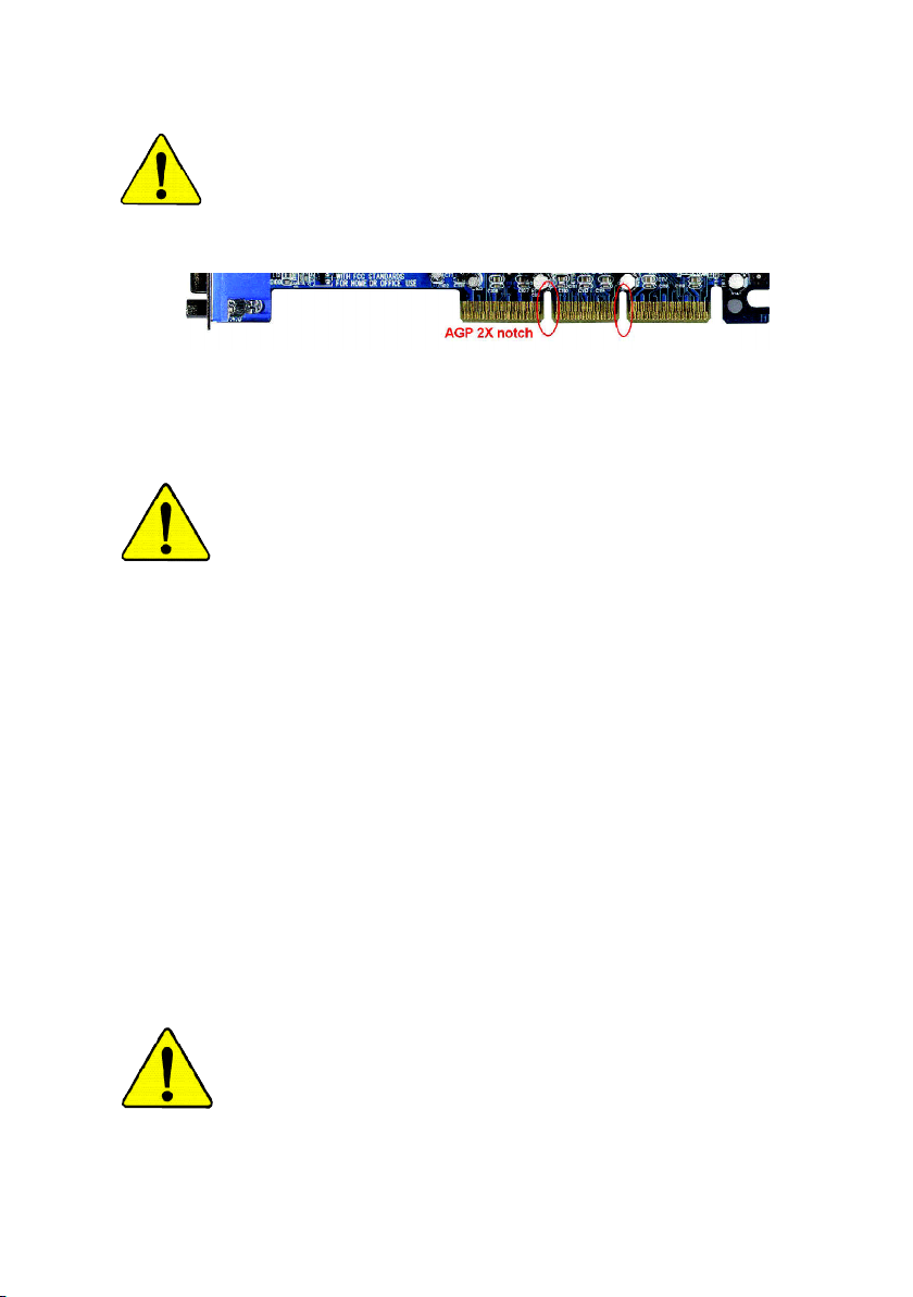
When you installing AGP card, please make sure the following
notice is fully understood and practiced. If your AGP card has
"AGP 4X/8X(1.5V) notch"(show below), please make sure your AGP
card is AGP 4X/8X(1.5V).
AGP 4X/8X notch
Caution: AGP 2X card is not supported by SiS® 655. You might
experience system unable to boot up normally. Please insert an
AGP 4X/8X card.
Example 1: Diamond Vipper V770 golden finger is compatible with 2X/4X
mode AGP slot. It can be switched between AGP 2X(3.3V) or 4X(1.5V)
mode by adjusting the jumper. The factory default for this card is
2X(3.3V). The GA-GA-SINXP1394 (or any AGP 4X only)
motherboards might not function properly, if you install this card without
switching the jumper to 4X(1.5) mode in it.
Example 2: Some ATi Rage 128 Pro graphics cards made by "Power
Color", the graphics card manufacturer & some SiS 305 cards, their
golden finger is compatible with 2X(3.3V)/4X(1.5V) mode AGP slot, but
they support 2X(3.3V) only. The GA-SINXP1394
(or any AGP 4X only) motherboards might not function properly, If you
install this card in it.
Note : Although Gigabyte's AG32S(G) graphics card is based on
ATi Rage 128 Pro chip, the design of AG32S(G) is compliance
with AGP 4X(1.5V) specification. Therefore, AG32S (G)will work
fine with SiS® 648 based motherboards.
Before you install PCI cards, please remove the Dual BIOS label from
PCI slots if there is one.
M The author assumes no responsibility for any errors
or omissions that may appear in this document nor
does the author make a commitment to update the
information contained herein.
M Third-party brands and names are the property of
their respective owners.
M Please do not remove any labels on motherboard, this
may void the warranty of this motherboard.
M Due to rapid change in technology, some of the
specifications might be out of date before publication
of this booklet.

Ausschla ger Weg 41, 1F, 20537 Hamburg, Germany
( description of the apparatus, system, installation to which it refers)
(reference to the specification under which conformity is declared)
in accordance with 89/336 EEC-EMC Directive
o EN 55011 Limits and methods of measurement
o EN 55013
o EN 55014 Limits and methods of measurement
o EN 55015 Limits and methods of measurement
o EN 55020
T EN 55022 Limits and methods of measurement
o DIN VDE 0855
o part 10
o part 12
T CE marking
o EN 60065
o EN 60335
of radio disturbance characteristics of
industrial,scientific and medical (ISM
high frequency equipment
Limits and methods of measurement
of radio disturbance characteristics of
broadcast receivers and associated
equipment
of radio disturbance characteristics of
household electrical appliances,
portable tools and similar electrical
apparatus
of radio disturbance characteristics of
fluorescent lamps and luminaries
Immunity from radio interference of
broadcast receivers and associated
equipment
of radio disturbance characteristics of
information technology equipment
Cabled distribution systems; Equipment
for receiving and/or distribution from
sound and television signals
The manufacturer also declares the conformity of above mentioned product
with the actual required safety standards in accordance with LVD 73/23 EEC
Safety requirements for mains operated
electronic and related apparatus for
household and similar general use
Safety of household and similar
electrical appliances
(Stamp)
Declaration of Conformity
We, Manufacturer/Importer
(full address)
G.B.T. Technology Träding GMbH
declare that the product
Mother Board
GA-SINXP1394
is in conformity with
o EN 61000-3-2*
T EN 60555-2
o EN 61000-3-3* Disturbances in supply systems cause
T EN 60555-3
T EN 50081-1
T EN 50082-1
o EN 55081-2
o EN 55082-2
o ENV 55104
o EN50091-2
(EC conformity marking)
o EN 60950
o EN 50091-1
Manufacturer/Importer
Date : January 6, 2002
Disturbances in supply systems cause
by household appliances and similar
electrical equipment “Harmonics”
by household appliances and similar
electrical equipment “Voltage fluctuations”
Generic emission standard Part 1:
Residual commercial and light industry
Generic immunity standard Part 1:
Residual commercial and light industry
Generic emission standard Part 2:
Industrial environment
Generic emission standard Part 2:
Industrial environment
lmmunity requirements for household
appliances tools and similar apparatus
EMC requirements for uninterruptible
power systems (UPS)
Safety for information technology equipment
including electrical bussiness equipment
General and Safety requirements for
uninterruptible power systems (UPS)
Signature:
Name:
Timmy Huang
Timmy Huang

DECLARATION OF CONFORMITY
Per FCC Part 2 Section 2.1077(a)
Responsible Party Name:
Add ress:
Phone/Fax No:
hereby declares that the product
Produ ct Name:
Model Nu mber:
Conforms to the following specifications:
FCC Part 15, Subpart B, Section 15.107(a) and Section 15.109
(a),Class B Digital D evice
Supplementary Information:
This device complies with part 15 of the FCC Rules. Operation is
subject to the following two conditions: (1) This device may not
cause harmful and (2) this device must accept any inference received,
including that may cause undes ired operation.
Representative Person’s Name:
Signature:
G.B.T. INC. (U .S.A.)
17358 Railroad Street
City of Indu stry, CA 91748
(818) 854-9338/ (818) 854-9339
Motherboard
GA-SINXP1394
ERIC LU
Eric Lu
Date:
January 6, 2002

GA-SINXP1394
P4 Titan DDR Motherboard
USER'S MANUAL
Pentium®4 Processor Motherboard
Rev. 1001
12ME-SINXP-1001

English
Item Checklist ..................................................................................... 4
WARNING! .......................................................................................... 4
Chapter 1 Introduction .........................................................................5
Chapter 2 Hardware Installation Process .............................................. 9
Table of Content
Features Summary ......................................................................................... 5
GA-SINXP1394 Motherboard Layout ............................................................ 8
Step 1: Install the Central Processing Unit (CPU) ...................................... 10
Step1-1 : CPU Installation ......................................................................................... 10
Step1-2 : CPU Heat Sink Installation ......................................................................... 11
Step 2: Install memory modules .................................................................. 12
Step 3: Install expansion cards .................................................................... 14
Step 3-1: AGP Ca rd Install ation .................................................................................14
Step 3-2: DPVRM ( Dual Power Voltage Regulator Mod ule) Instal lation ....................15
Step 4: Connect ribbon cables, cabinet wires, and power supply ............ 16
Step 4-1: I/O Back Panel Introduction ....................................................................... 16
Step 4-2: Connectors Introduction .............................................................................18
Chapter 3 BIOS Setup .......................................................................29
The Main Menu (For example: BIOS Ver. : F1) ......................................... 30
Standard CM OS Features ........................................................................... 32
Advanced BIOS Features ............................................................................. 35
Integrated Peripherals ................................................................................. 38
Power Management Setup .......................................................................... 42
- 2 -GA-SINXP1394 Motherboard

PnP/PCI Configurations ................................................................................ 44
PC Health Status ........................................................................................... 4 5
Frequency/Voltage Control ........................................................................... 4 7
Top Performance .......................................................................................... 4 9
Load Fail-Safe Defaults ................................................................................ 50
Load Optimized Defaults .............................................................................. 51
Set Supervisor/User Password..................................................................... 52
Save & Exit Setup .......................................................................................... 5 3
Exit Without Saving ....................................................................................... 54
Chapter 4 Technical Reference .......................................................... 57
Block Diagram ............................................................................. 57
@ BIOS
Easy TuneTM 4 Introduction .......................................................................... 59
DPS (Dual Power System) Introduction ...................................................... 6 0
Dual BIOS/Q-Flash Introduction .................................................................. 61
TM
Introduction ................................................................... 58
English
2-/4-/6-Channel Audio Function Introuction .................................... 82
Chapter 5 Appendix .......................................................................... 89
- 3 -
Tabl e of Content
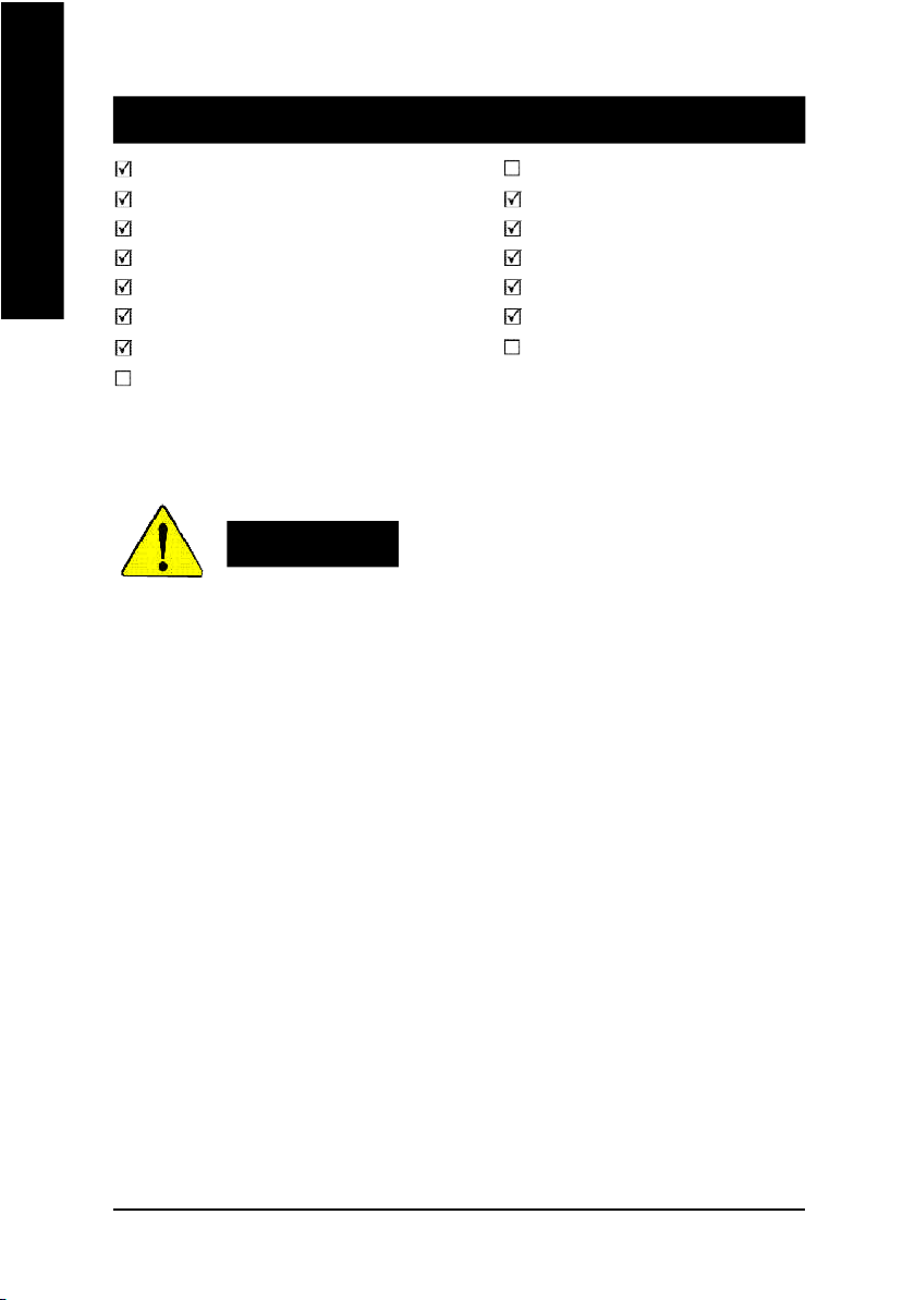
Item Checklist
English
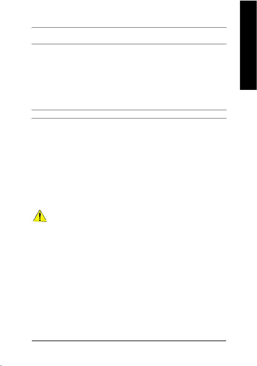
Computer motherboards and expansion cards contain very delicate Integrated Circuit (IC) chips. To
protect them against damage from static electricity, you should follow some precautions whenever you
work on your computer.
Installing the motherboard to the chassis…
no slots to attach the spacers, do not become alarmed you can still attach the spacers to the mounting
holes. Just cut the bottom portion of the spacers (the spacer may be a little hard to cut off, so be careful
of your hands). In this way you can still attach the motherboard to the base without worrying about short
circuits. Sometimes you may need to use the plastic springs to isolate the screw from the motherboard
PCB surface, because the circuit wire may be near by the hole. Be careful, don't let the screw contact
any printed circuit write or parts on the PCB that are near the fixing hole, otherwise it may damage the
board or cause board malfunctioning.
The GA-SINXP1394 motherboard 2 Port USB Cable x 1
CD for motherboard drive r & utility 4 Por t USB C able x 1
GA-SINXP1394 user's m anual SPDIF Kit x 1(SPD-K IT)
Quick PC Installation Guide SATA cable x2
ITE RAID Manual I/O Shield
SATA RAID Ma nual Motherboard Settings Label
IDE ca ble x3 / F loppy cable x 1 GC-S1394 Card (Optional)
GC-SATA Card (Optional) (Manual)
(M anual ; SATA cable x1 ; Powe r cabl e x 1)
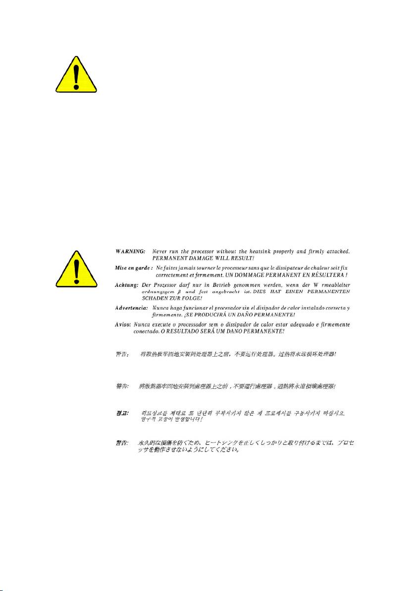
WARNING!
1. Unplug your computer when working on the inside.
2. Use a grounded wrist strap before handling computer components. If you do not have
one, touch both of your hands to a safely grounded object or to a metal object, such as
the power supply case.
3. Hold components by the edges and try not touch the IC chips, leads or connectors, or
other components.
4. Place components on a grounded antistatic pad or on the bag that came with the
components whenever the components are separated from the system.
5. Ensure that the ATX power supply is switched off before you plug in or remove the ATX
power connector on the motherboard.
If the motherboard has mounting holes, but they don't line up with the holes on the base and there are
- 4 -GA-SINXP1394 Motherboard

Chapter 1 Introduction
Features Summary
Form Factor — 30.5cm x 24.4cm ATX size form factor, 6 layers PCB.
CPU — Socket 478 for Intel® Micro FC-PGA2 Pentium® 4 processor
— Support Intel ® Pentium ® 4 (Northwood, 0.13 m) processor
— Support Intel ® Pentium ® 4 Processor with HT Technology
— Intel Pentium®4 400/533MHz FSB
— 2nd cache depends on CPU
Chipset — SiS 655 Host/Memory controller
— SiS 963 MuTIOL Media I/O
Memory — 4 184-pin DDR DIMM sockets
— Supports Dual channel DDR400
— Supports 128MB/256MB/512MB/1GB unbuffered DRAM
— Supports up to 4GB DRAM (Max)
— Supports only 2.5V DDR DIMM
I/O Control — IT8705F
Slots — 1 AGP 3.0 slot supports 8X/4X mode
— 5 PCI slot supports 33MHz & PCI 2.2 compliant
On-Board IDE — 2 IDE controllers provides IDE HDD/CD-ROM (IDE1, IDE2)
with PIO, Bus Master (Ultra DMA33/ATA66/ATA100/ATA133)
operation modes
— IDE3 and IDE4 Compatible with RAID,Ultra ATA133/100, EIDE
Serial ATA — 2 Serial ATA connectors in 150 MB/s operation mode
— Controlled by Silicon Image SiI3112A
<Note 1>
/DDR333/DDR266 DIMM
English
to be continued......
<Note 1> DDR400 recommended memory modules are listed in GIGABYTE website.
- 5 -
Introduction

On-Board Peripherals — 1 Floppy port supports 2 FDD with 360K, 720K,1.2M, 1.44M
English
Hardware Monitor — CPU/System Fan Revolution detect
On-Board Sound — Realtek ALC650 CODEC
On-Board RAID — Onboard ITE IT8212F
On-Board LAN — Builit in Intel® RC82540EM (KENAI 32) Chipset
PS/2 Connector — PS/2 Keyboard interface and PS/2 Mouse interface
and 2.88M bytes.
— 1 Parallel port supports Normal/EPP/ECP mode
— 2 Serial ports (COMA&COMB)
— 6 USB 2.0/1.1 ports (2 x Rear, 4 xFront by cable)
— 1 Front Audio Connector
— 1 IrDA connector for IR
— CPU/System Fan Fail Warning
— CPU Overheat Warning
— System Voltage Detect
— Line Out / 2 front speaker
— Line In / 2 rear speaker(by s/w switch)
— Mic In / center& subwoofer(by s/w switch)
— SPDIF out /SPDIF IN
— CD In / AUX_IN / Game Port
— Supports data striping (RAID 0) or mirroring (RAID 1) or
striping+mirroring (RAID 0+RAID 1)
— Supports JBOD function
— Supports concurrent dual ATA133 IDE controller operation
— Support ATAPI mode for HDD
— Supports IDE bus master operation
— Support ATA133/RAID mode switch by BIOS
— Displays status and error checking messages during boot-up
— Mirroring supports automatic background rebuilds
— Features LBA and Extended Interrupt 13 drive translation in
controller onboard BIOS
— 1 RJ45 port
to be continued......
- 6 -GA-SINXP1394 Motherboard
BIOS — Licensed AWARD BIOS, 2M bit Flash ROM
— Supports Dual BIOS / Q-Flash
Additional Features — PS/2 Keyboard power on by password
— PS/2 Mouse power on
— STR(Suspend-To-RAM)
— AC Recovery
— USB KB/Mouse wake up from S3
— Poly fuse for keyboard over-current protection
— Supports EasyTune 4
— Supports @BIOS
Overclocking — Over Voltage (CPU/DRAM/AGP) by BIOS
HT functionality requirement content
"Enabling the functionality of Hyper-Threading Technology for your computer
system requires all of the following platform components:
- CPU: An Intel® Pentium 4 Processor with HT Technology
- Chipset: An SiS® Chipset that supports HT Technology
- BIOS: A BIOS that supports HT Technology and has it enabled
- OS: An operation system that has optimizations for HT Technology
English
Please set the CPU host frequency in accordance with your processor's specifications.
We don't recommend you to set the system bus frequency over the CPU's specification
because these specific bus frequencies are not the standard specifications for CPU,
chipset and most of the peripherals. Whether your system can run under these specific
bus frequencies properly will depend on your hardware configurations, including CPU,
Chipsets,SDRAM,Cards… .etc.
- 7 -
Introduction
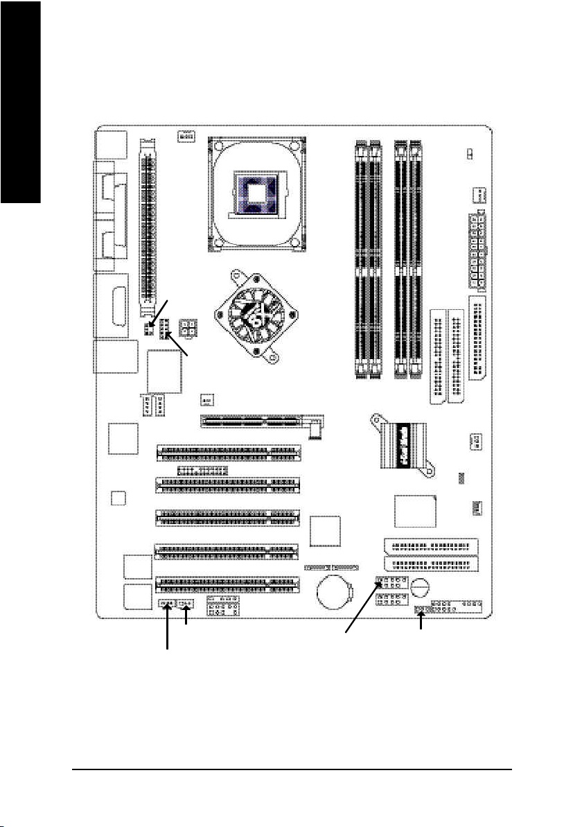
GA-SINXP1394 Motherboard Layout
English
KB_M S
COMA
COMB
LINE_OUT
LINE_IN
MIC_IN
USB_LAN
Inte l
KENAI 32
CODEC
LPT
GAME
CD _IN
Ma in
BIOS
Back up
BIOS
CPU_FAN
VRM_CON N
SOC KET4 78
SUR_C EN
ATX_12 V
F_AU DIO
IT8705F
AUX_IN
NB_FAN
1 39 4
AGP 8X DDR 400
P4 Titan
SPDIF_O
SPDIF_IN
IR
SMB_CONN
SiS 6 55
PCI3
PCI5
AGP
PCI1
PCI2
Silicon Ima ge
SiI3 112A
PCI4
S_ ATA2 S_ ATA 1
BAT
F_U SB2
GA-SINXP1394
DDR2
DDR3
DDR4
SiS 9 63
GigaRAID
IT8212F
IDE4
IDE3
F_U SB1
PWR_FAN
IDE2
DDR1
SYS _FAN
BUZZER
PWR_ LED
LED
ATX
IDE1
FD D
CI
WOL
F_PANEL
- 8 -GA-SINXP1394 Motherboard
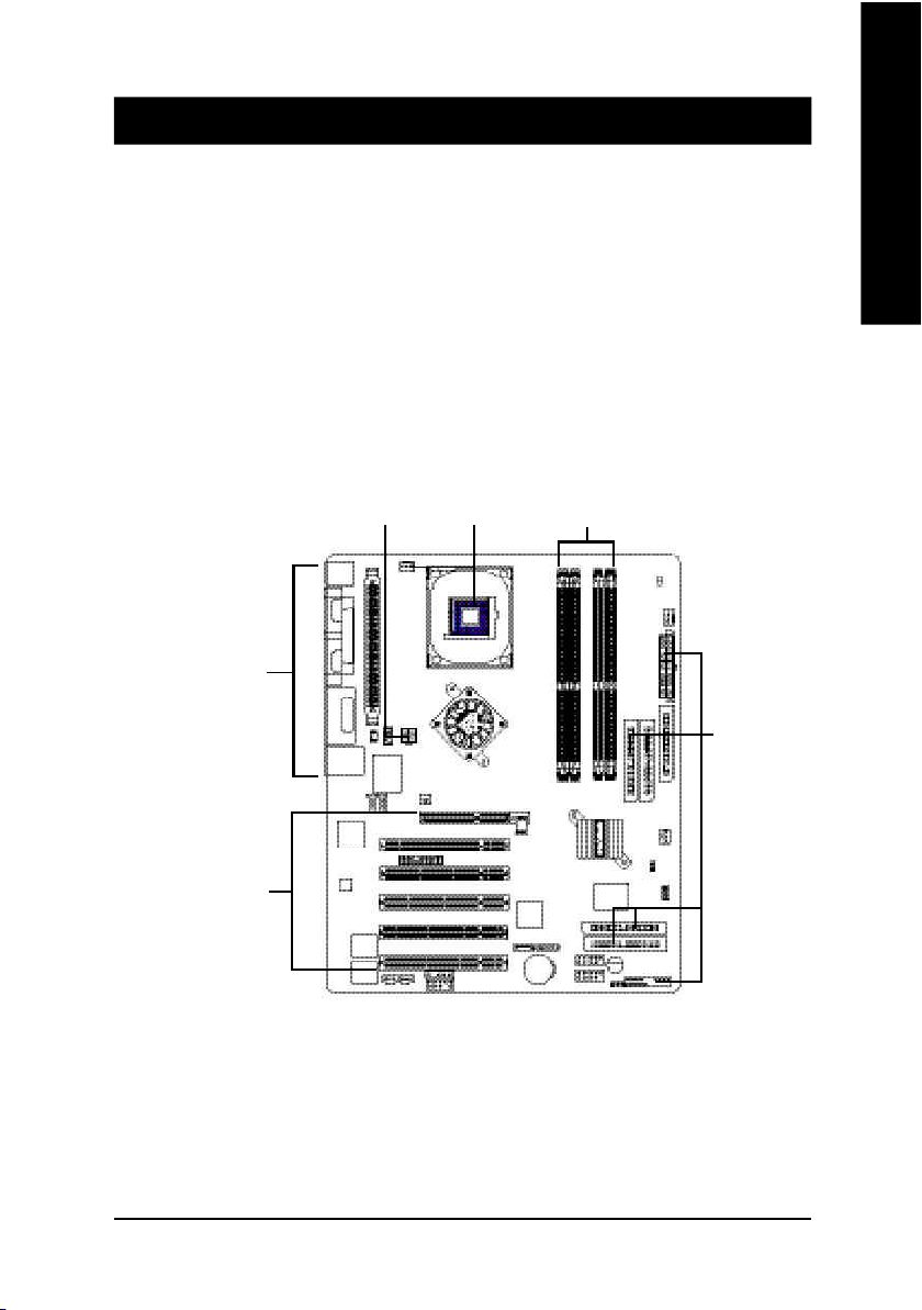
Chapter 2 Hardware Installation Process
To set up your computer, you must complete the following steps:
Step 1- Install the Central Processing Unit (CPU)
Step 2- Install memory modules
Step 3- Install expansion cards
Step 4- Connect ribbon cables, cabinet wires, and power supply
Step 5- Setup BIOS software
Step 6- Install supporting software tools
English
Step 4
Step 3
Step 4 Step 1
Step 2
Step 4
- 9 - Hardware Installation Proc ess
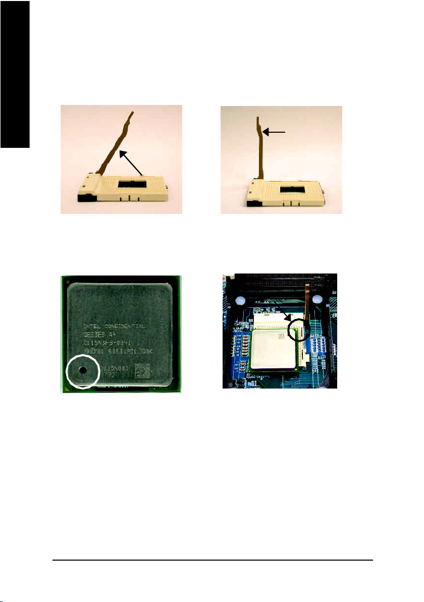
Step 1: Install the Central Processing Unit (CPU)
Step1-1 : CPU Installation
English
Angling the
rod to 65
1. Angling the rod to 65-degree maybe feel
a kind of tight, and then continue pull the
rod to 90-degree when a noise "cough"
made.
0
Pin1 indicator
3. CPU Top V iew
Socket
Actuation
Lever
2. Pull the rod to the 90-degree directly.
Pin1 indicator
4. Locate Pin 1 in the socket and look
for a (golden) cut edge on the CPU
upper corner. Then insert the CPU
into the socket.
M Please make sure the CPU type is supported by the motherboard.
M If you do not match the CPU socket Pin 1 and CPU cut edge well, it will cause
improper installation. Please change the insert orientation.
- 10 -GA-SINXP1394 Motherboard
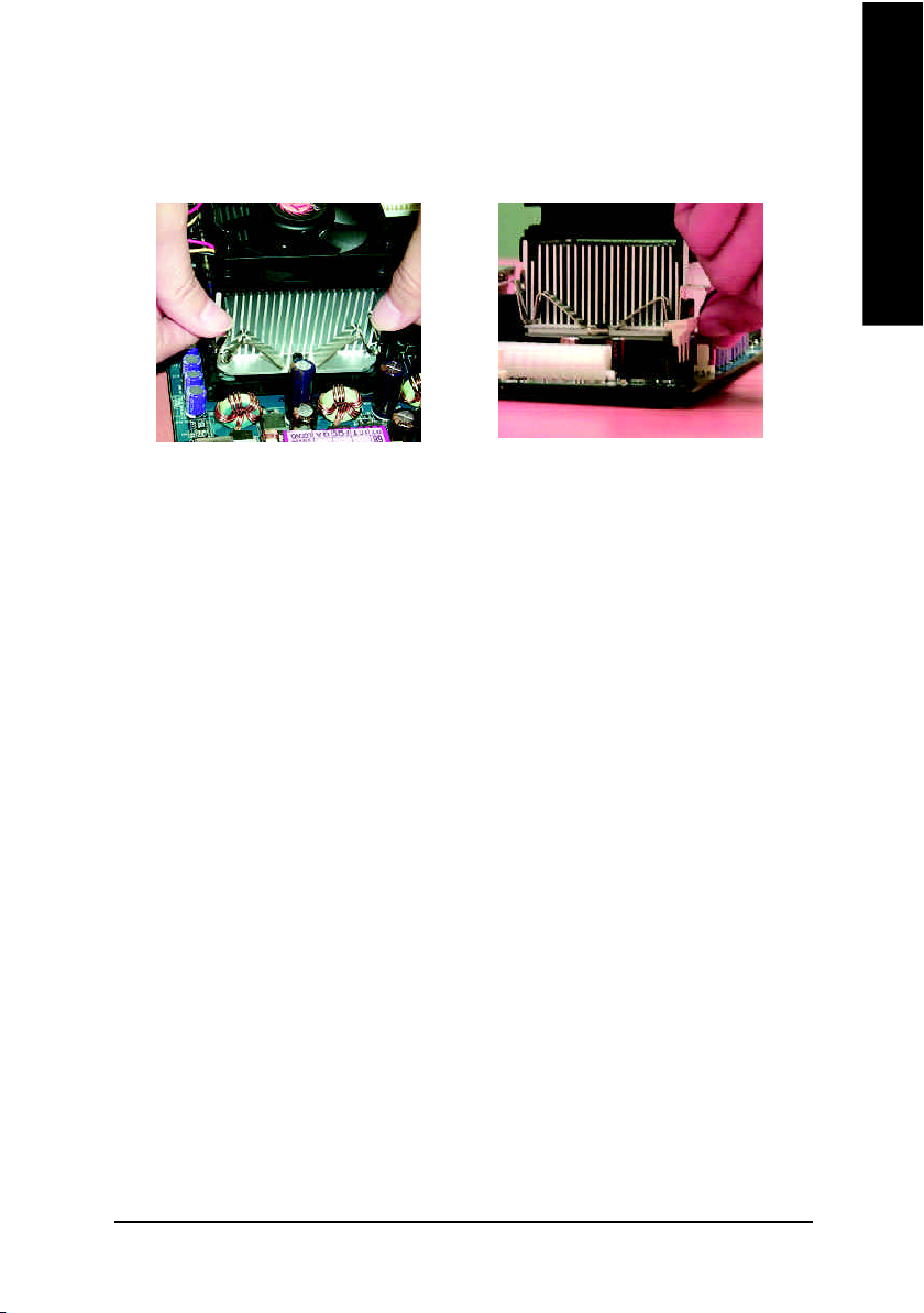
Step1-2 : CPU Heat Sink Installation
English
1. Hook one end of the cooler
bracket to the CPU socket first.
2. Hook the other end of the
cooler bracket to the CPU
socket.
M Please use Intel approved cooling fan.
M We recommend you to apply the thermal tape to provide better heat
conduction between your CPU and heatsink.
(The CPU cooling fan might stick to the CPU due to the hardening of the
thermal paste. During this condition if you try to remove the cooling fan, you
might pull the processor out of the CPU socket alone with the cooling fan, and
might damage the processor. To avoid this from happening, we suggest you
to either use thermal tape instead of thermal paste, or remove the cooling fan
with extreme caution.)
M Make sure the CPU fan power cable is plugged in to the CPU fan connector,
this completes the installation.
M Please refer to CPU heat sink user's manual for more detail installation
procedure.
- 11 - Hardware Installation Proc ess
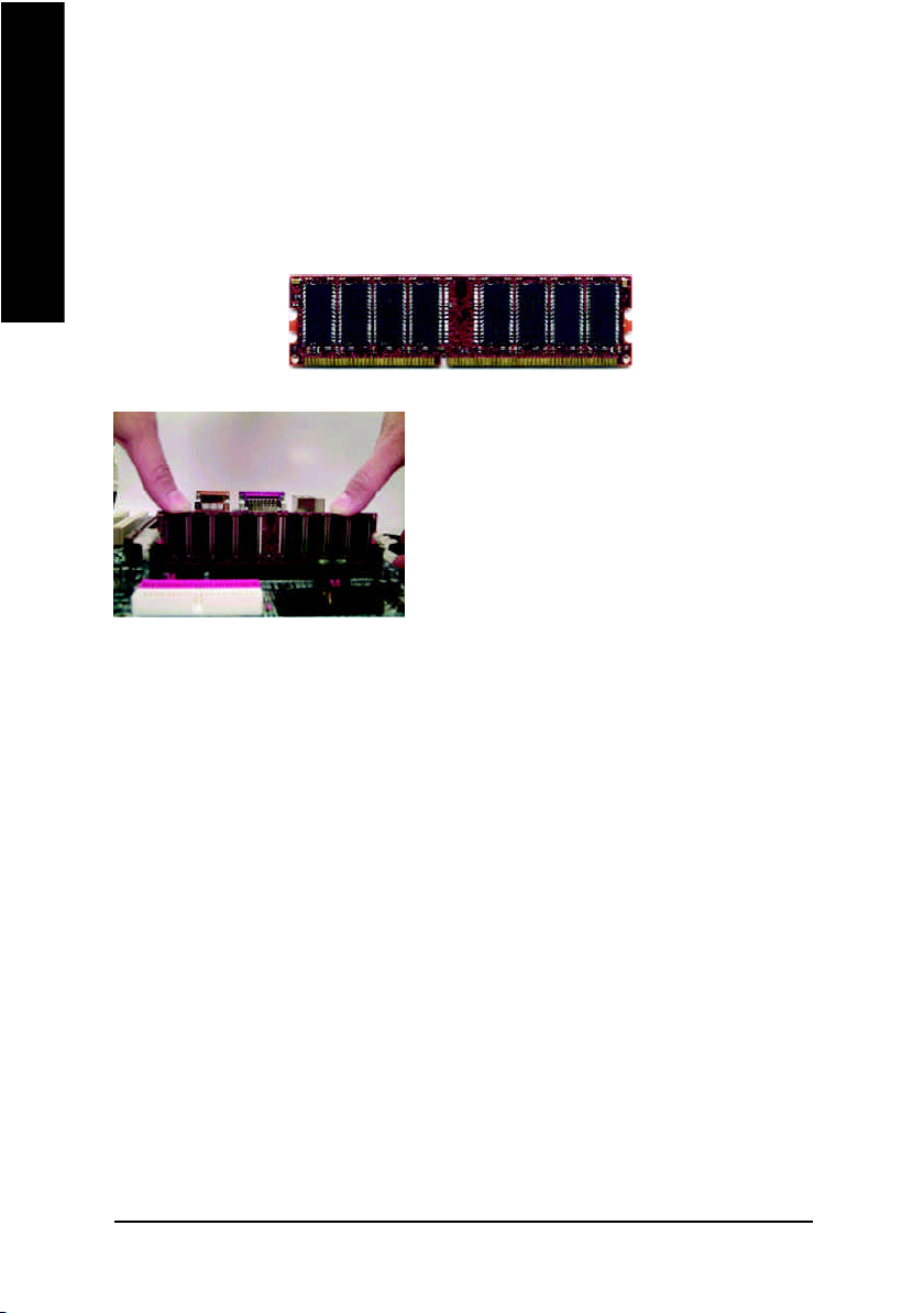
Step 2: Install memory modules
The motherboard has 4 dual inline memory module (DIMM) sockets. The BIOS will automatically
English
detects memory type and size. To install the memory module, just push it vertically into the DIMM
socket. The DIMM module can only fit in one direction due to the notch. Memory size can vary between
sockets.
M When LED is ON, do not install/remove DIMM from socket.
M Please note that the DIMM module can only fit in one direction due to the one
DDR
1. The DIMM socket has a notch, so the DIMM memory
module can only fit in one direction.
2. Insert the DIMM memory module vertically into the
DIMM socket. Then push it down.
3. Close the plastic clip at both edges of the DIMM
sockets to lock the DIMM module.
Reverse the installation steps when you wish to
remove the DIMM module.
notches. Wrong orientation will cause improper installation. Please change
the insert orientation.
DDR Introduction
Established on the existing SDRAM industry infrastructure, DDR (Double Data Rate) memory is a
high performance and cost-effective solution that allows easy adoption for memory vendors, OEMs and
system integrators.
DDR memory is a sensible evolutionary solution for the PC industry that builds on the existing
SDRAM infrastructure, yet makes awesome advances in solving the system performance bottleneck by
doubling the memory bandwidth. DDR SDRAM will offer a superior solution and migration path from
existing SDRAM designs due to its availability, pricing and overall market support. PC2100 DDR
memory (DDR266) doubles the data rate through reading and writing at both the rising and falling edge of
the clock, achieving data bandwidth 2X greater than PC133 when running with the same DRAM clock
frequency. With peak bandwidth of 2.664GB per second, DDR memory enables system OEMs to build
high performance and low latency DRAM subsystems that are suitable for servers, workstations, highend PC's and value desktop SMA systems. With a core voltage of only 2.5 Volts compared to
conventional SDRAM's 3.3 volts, DDR memory is a compelling solution for small form factor desktops
and notebook applications.
- 12 -GA-SINXP1394 Motherboard
GA-SINXP1394 supports the Dual Chann el Technology. After op erating the Dual Channel Technology,
the bandwidth of M emor y Bus will add double up to 5.4GB /s.
GA-SINXP1394 includes 4 DIM M sockets, and each Channel ha s two DIMM sockets as following:
Channel A : DIMM 1, DIMM 2
Channel B : DIMM 3, DIMM 4
If you want to o perate the Dual Channel Technology, please note the following explanations due
to the limitation of SiS® chipset specifications.
1. Only one DDR memory m odule is installed: The Dual Channel Technology can't operate
when only one DDR mem ory m odule is installed.
2. Two DDR me mory mo dules are in stalled (the sam e me mory s ize and type): The Dual
Channel Techno logy will operate when two mem ory mod ules are in serted ind ividually i nto
Channel A and B. If yo u install two mem ory modules in the same cha nnel, the Dual Channel
Te chnology will n ot operate. Add itionally, you can boot the sy stem only when one of the
mem ory m odules is inserted into Channel A or Chann el B. On the other hand, the mem ory
modu le must be inserted into an y sockets.
3. Three DDR mem ory modules are installed: If you install three m emory m odules at the sam e
time, the Dual Cha nnel Technology will operate only when those m odules have the same
me mory size and type.
4. Four DDR m emo ry m odules are in stalled: If you install four mem ory m odules at the same
time, the Dual Cha nnel Technology will operate only when those m odules have the same
me mory size and type.
We'll strongly recommend our user to slot into two DDR memory modules into the DIMMs with the same
color in order for Dual Channel Technology to work.
The following tables include all memory-installed combination types:
(Please n ote that tho se types not in the tables will not boot up.)
English
l Figure 1: Dual Channe l Technology (DS: Double Side, SS: Single Side)
DIMM 1 DIMM 2 DIMM 3 DIMM 4
2 memory modules
3 memory modules
4 memory modules
DS/SS X DS/SS X
DS/SS X X DS/SS
X DS/SS DS/SS X
X DS/SS X DS/SS
DS/SS DS/SS DS/SS X
DS/SS DS/SS X DS/SS
DS/SS X DS/SS DS/SS
X DS/SS DS/SS DS/SS
DS/SS DS/SS DS/SS DS/SS
- 13 - Hardware Installation Proc ess
English
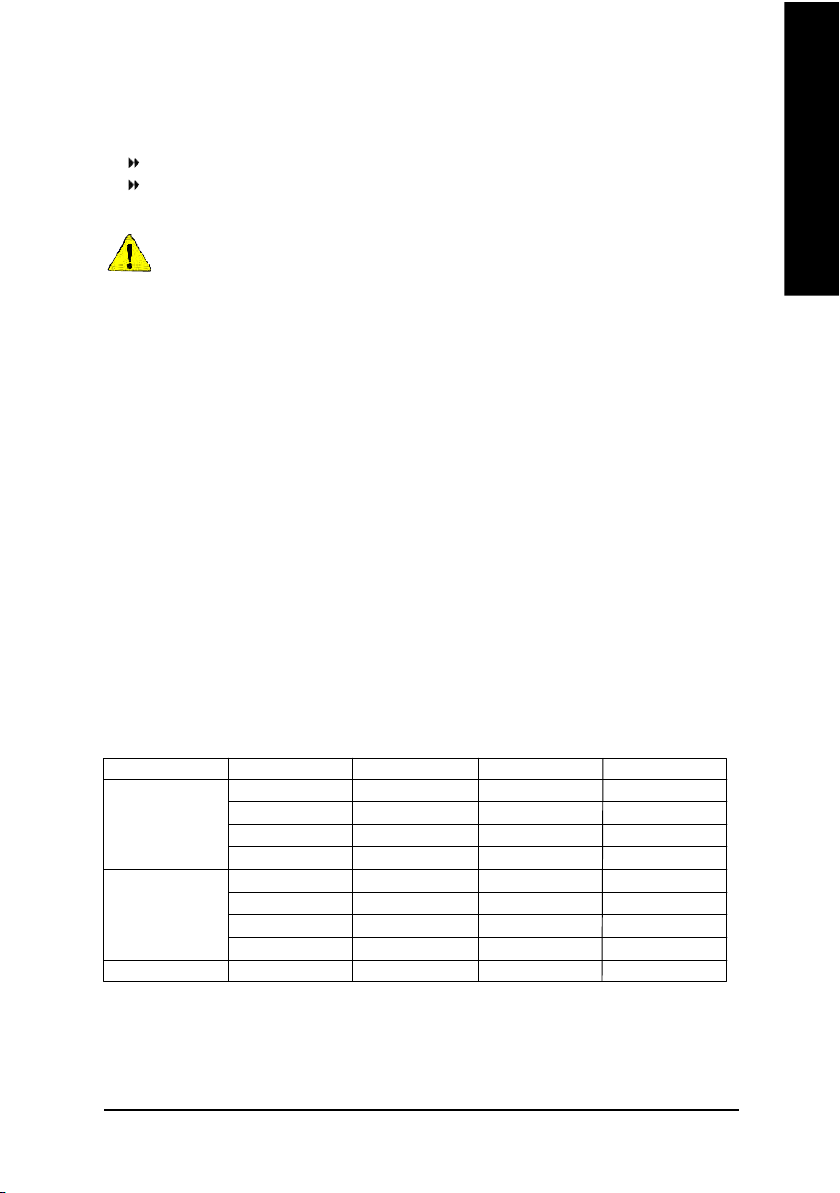
Step 3: Install expansion cards
Step 3-1: AGP Card Installation
1. Read the related expansion card's instruction document before install the expansion card into
2. Remove your computer's chassis cover, necessary screws and slot bracket from the computer.
3. Press the expansion card firmly into expansion slot in motherboard.
4. Be sure the metal contacts on the card are indeed seated in the slot.
5. Replace the screw to secure the slot bracket of the expansion card.
6. Replace your computer's chassis cover.
7. Power on the computer, if necessary, setup BIOS utility of expansion card from BIOS.
8. Install related driver from the operating system.
l Figure 2: Don't operate Dual Channel Technolog y (DS: Double Side, SS: Single Side)
DIMM 1 DIMM 2 DIMM 3 DIMM 4
1 me mory module
2 me mory modules
DS/SS X X X
X DS/SS X X
X X DS/SS X
X X X DS/SS
DS/SS DS/SS X X
X X DS/SS DS/SS
the computer.
AGP Card
Please carefully pull out the small whitedrawable bar at the end of the AGP slot when
you try to install/ Uninstall the AGP card.
Please align the AGP card to the onboard
AGP slot and press firmly down on the slot .
Make sure your AGP card is locked by the
small white- drawable bar.
- 14 -GA-SINXP1394 Motherboard
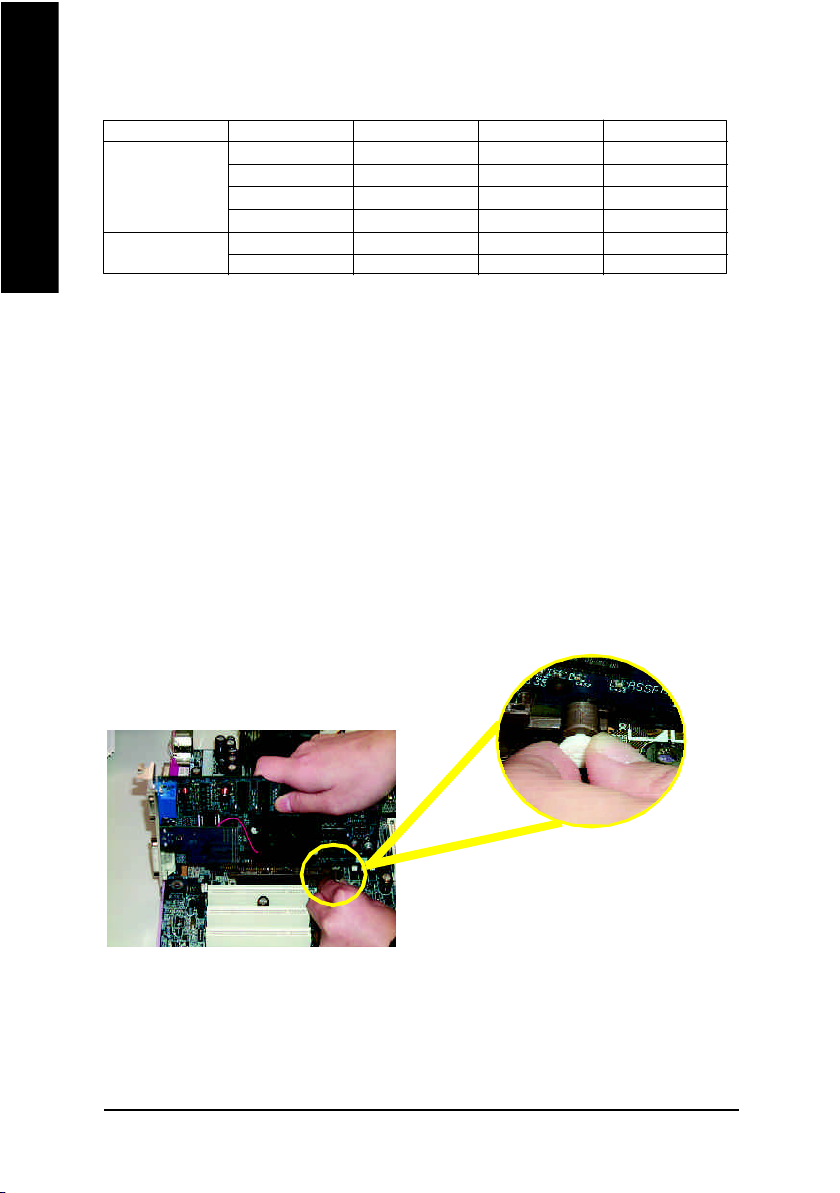
Step 3-2: DPVRM (Dual Power Voltage Regulator Module) Installation
What is DPVRM ?
DPVRM (Dual Power Voltage Regulator Module) is a daughter card which can provide you the DPS
(Dual Power System) function. A cool stylish neon blue DPVRM that supply a total 6-phase power circuit
design, delivers a high durable power design for the new generation Intel® platform.
The DPVRM can work in a Dual Power System:
• Parallel Mode :
DPVRM and motherboard CPU power can work
simultaneously, providing a total of 6-phase power circuit.
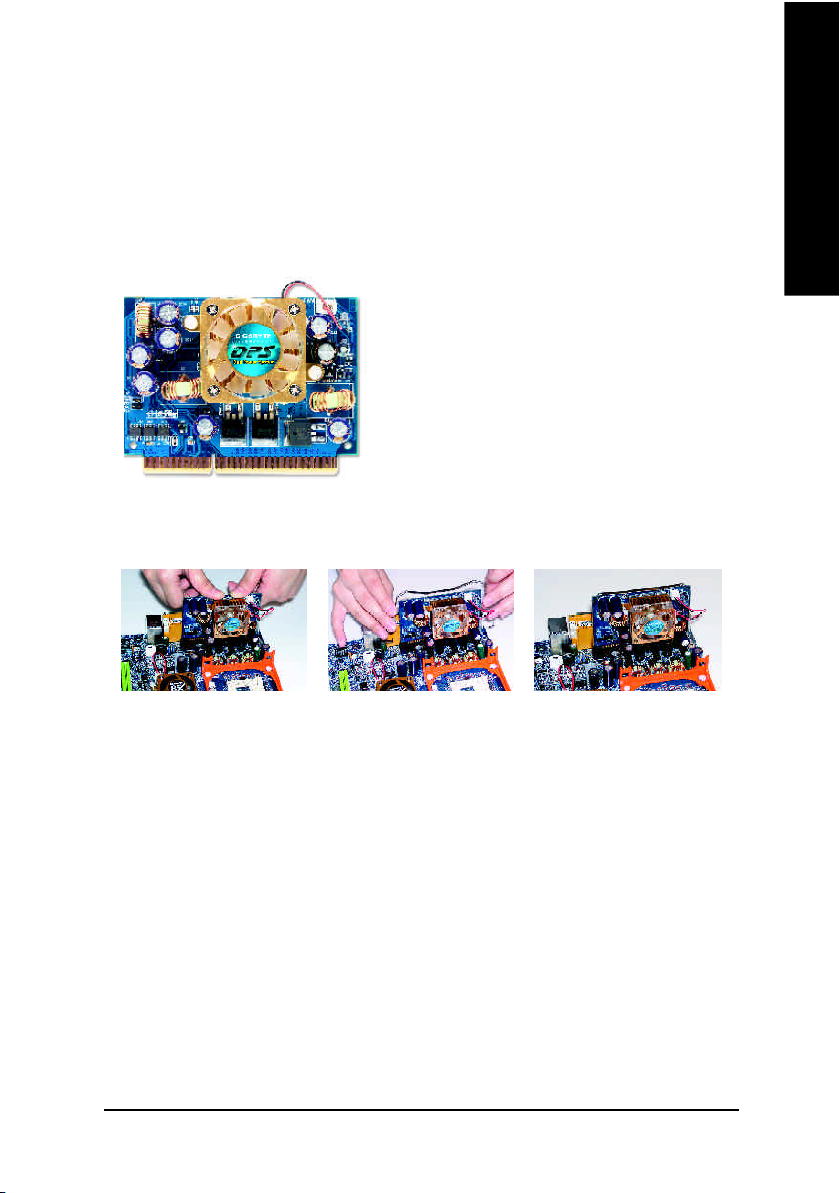
How to install a DPVRM ?
English
Step 1 Step 2 Step 3
1. The DPVRM connector has a notch, so the DPVRM can only fit in one direction.
2. Insert the DPVRM vertically into the socket and then push it down.
3. Fix the DPVRM on the motherbard with the clip.
4. Reverse the installation steps if you want to remove the DPVRM.
- 15 - Hardware Installation Proc ess
Step 4: Connect ribbon cables, cabinet wires, and power
English
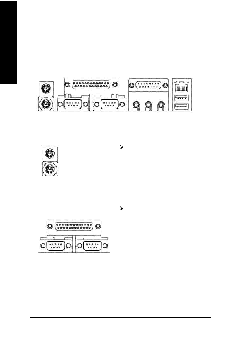
Step 4-1: I/O Back Panel Introduction
supply
u
v
w
x
u PS/2 Keyboard and PS/2 Mouse Connector
PS/2 Mouse Connector
(6 pin Female)
PS/2 Keyboard Connector
(6 pin Female)
This connector supports standard PS/2 keyboard
and PS/2 mouse.
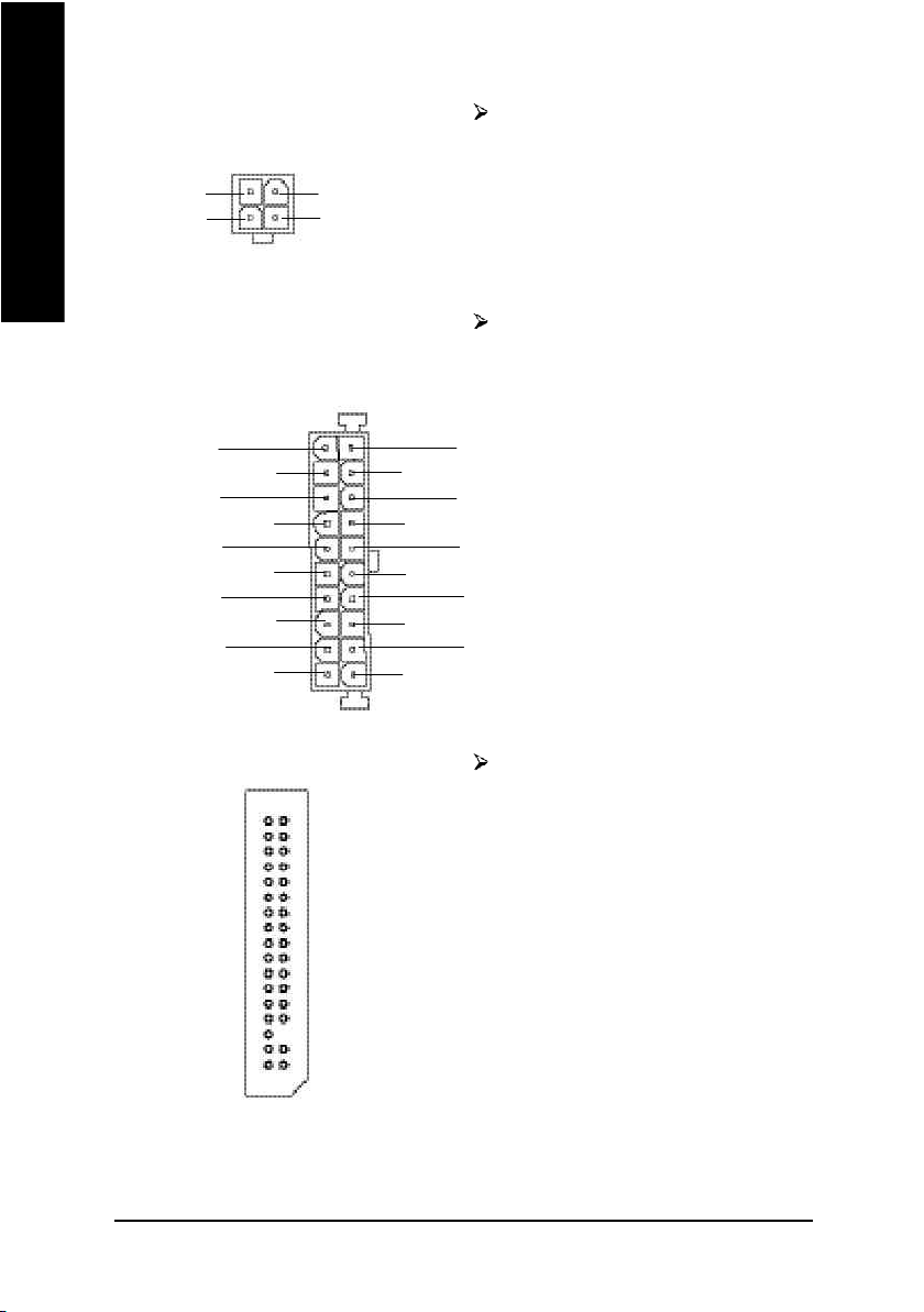
v Parallel Port and Serial Ports (COMA/COMB)
Parallel Port
(25 pin Female)
This connector supports 2 standard COM ports
and 1 Parallel port. Device like printer can be
connected to Parallel port ; mouse and modem
etc can be connected to Serial ports.
y
COMA COMB
Serial Port (9 pin Male)
- 16 -GA-SINXP1394 Motherboard
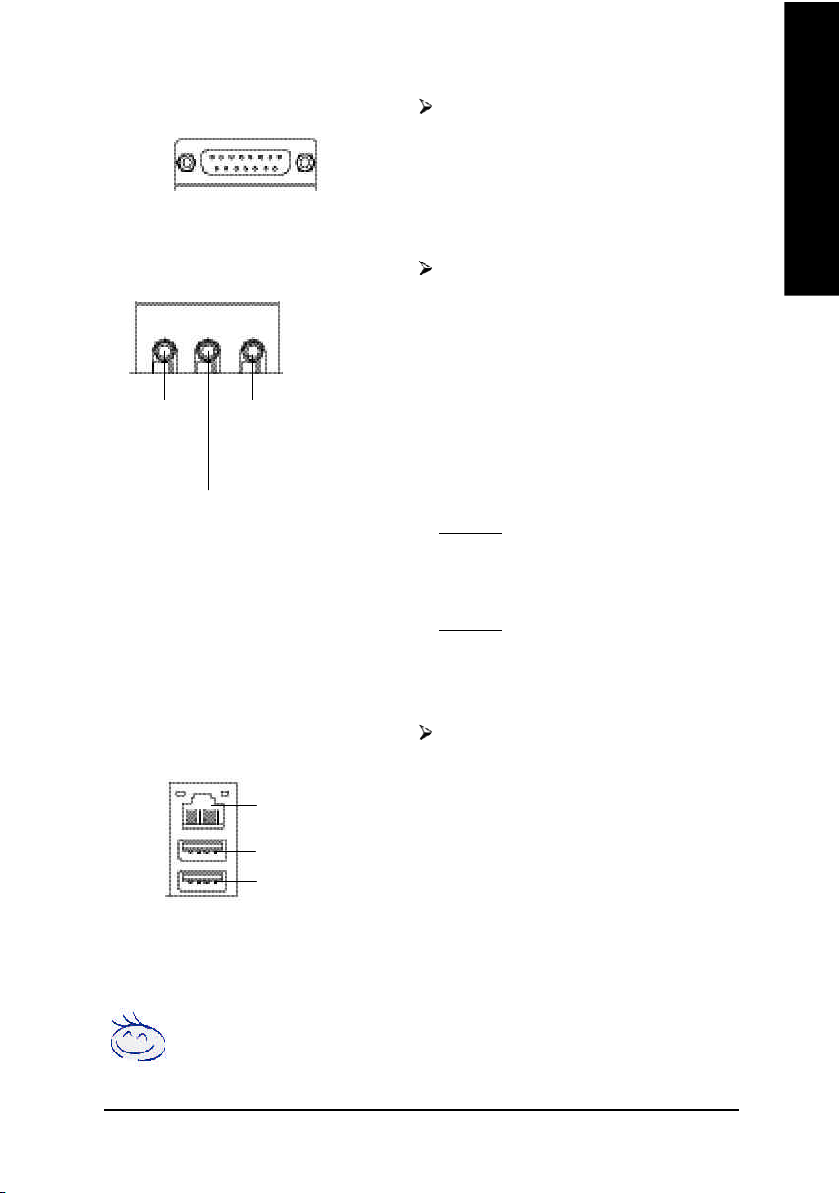
w Game /MIDI Ports
Joystick/ MIDI (15 pin Female)
This connector supports joystick, MIDI keyboard
and other relate audio devices.
English
x Audio Connectors
Line Out
(Front
Speaker)
(Rear Speaker)
MIC In
(Center and Subwoofer)
Line In
y USB & LAN Connector
LAN
USB 0
USB 1
After install onboard audio driver, you may
connect speaker to Line Out jack, micro phone to
MIC In jack.
Device like CD-ROM , walkman etc can be
connected to Line-In jack.
Please note:
You are able to use 2-/4-/6- channel audio feature
by S/W selection.
If you want to enable 6-channel function, you have
2 choose for hardware connection.
Method1:
Connect "Front Speaker" to "Line Out"
Connect "Rear Speaker" to "Line In"
Connect "Center and Subwoofer" to "MIC Out".
Method2:
You can refer to page 23, and contact your nearest
dealer for optional SUR_CEN cable.
Before you connect your device(s) into USB
connector(s), please make sure your device(s)
such as USB keyboard,mouse, scanner, zip,
speaker..etc. Have a standard USB interface.
Also make sure your OS supports USB controller.
If your OS does not support USB controller, please
contact OS vendor for possible patch or driver
upgrade. For more information please contact your
OS or device(s) vendors.
If you want the detail information for 2-/4-/6-channel audio setup
installation, please refer to page 82.
- 17 - Hardware Installation Proc ess
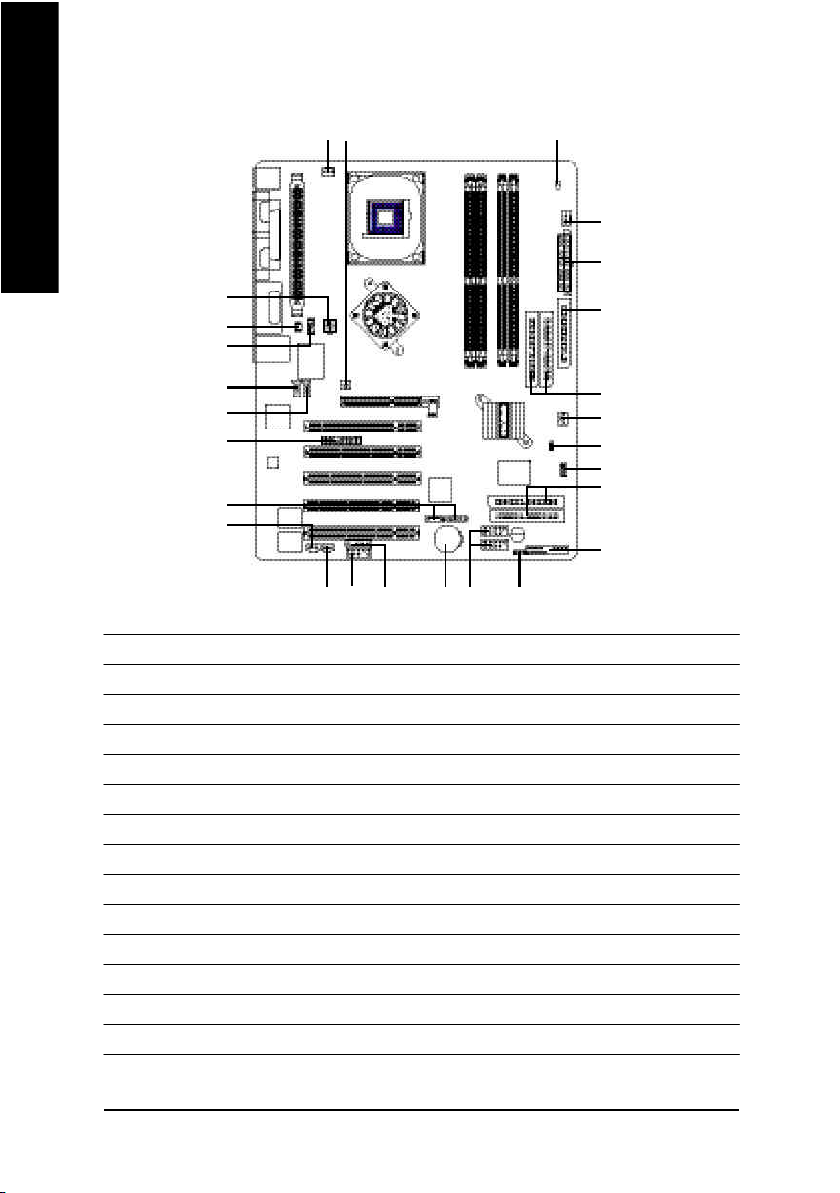
Step 4-2: Connectors Introduction
English
1
4
5
16
15
11
2
6
7
17
18
23
10
20
22
24
19
2114
12
1) CPU_FAN 15) F_AUDIO
2) PWR_FAN 16) SUR_CEN
3) SYS_FAN 17) CD_IN
4) NB_FAN 18) AUX_IN
5) ATX_12V 19) SPDIF_O
6) ATX 20) SPDIF_IN
7) FDD 21) F_USB1/F_USB2
8) IDE1/IDE2 22) SMB_CONN
9) IDE3/IDE4 23) 1394
10) S_ATA1/S_ATA2 24) IR
11) LED 25) C I
12) PWR_LED 26) WOL
13) F_PANEL
14) BAT
8
3
25
26
9
13
- 18 -GA-SINXP1394 Motherboard
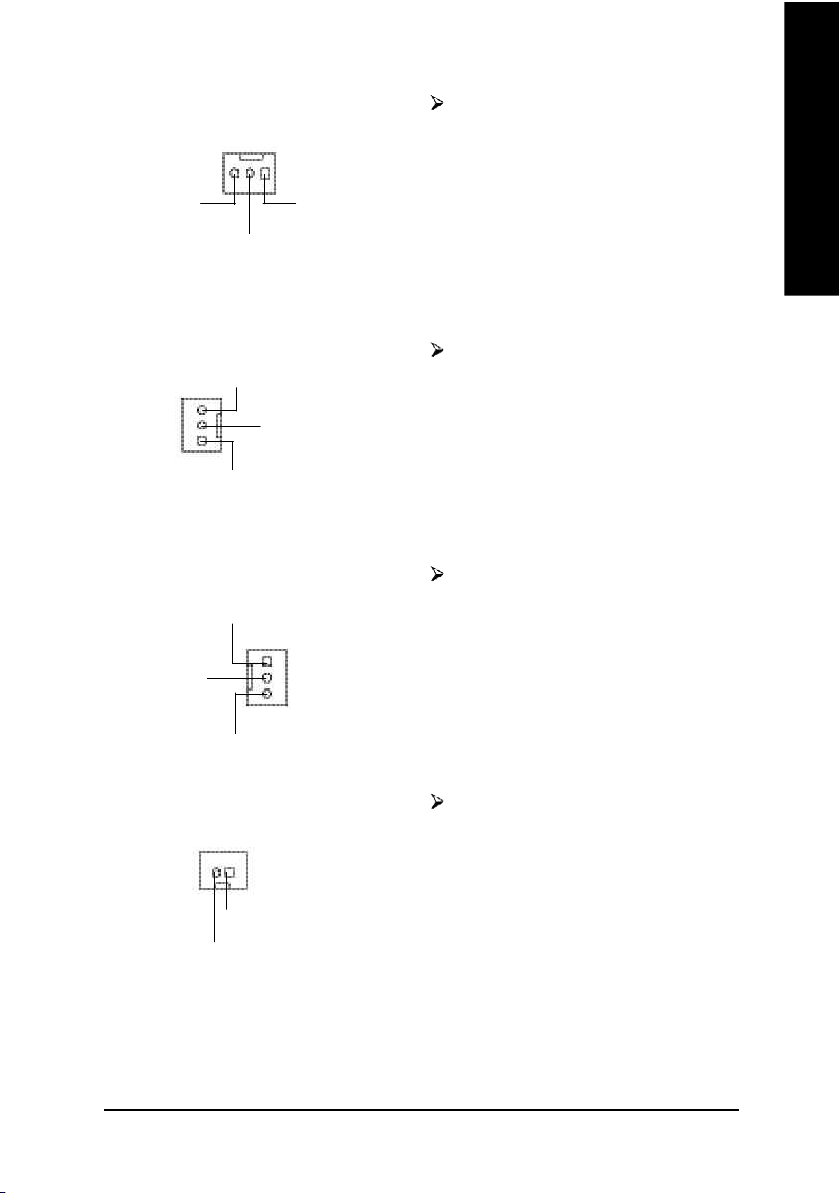
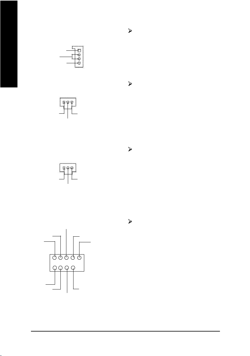
1) CPU_FAN (CPU FAN Connector)
1
Sense
+12V
GND
Please note, a proper installation of the CPU
cooler is essential to prevent the CPU from
running under abnormal condition or damaged
by overheating.The CPU fan connector
supports Max. current up to 600 mA.
English
2) PWR_FAN (Power Fan Connector)
Sense
+12V
1
GND
3) SYS_FAN (System FAN Connector)
GND
1
+12V
Sense
4) NB_FAN (Chip FAN Connector)
1
+12V
This connector allows you to link with the
cooling fan on the system case to lower the
system temperature.
This connector allows you to link with the
cooling fan on the system case to lower the
system temperature.
If you installed wrong direction, the Chip Fan
will not work. Sometimes will damage the Chip
Fan. (Usually black cable is GND)
GND
- 19 - Hardware Installation Proc ess
5) ATX_12V (+12V Power Connector)
English
GND
+12V
This connector (ATX_12V) supplies the CPU
operation voltage (Vcore).
1
2
GND
+12V
3
4
If this " ATX_12V connector" is not
connected, system cannot boot.
6) ATX (ATX Power)
+12V
5V SB (Stand by +5V)
Power Good
GND
VCC
GND
VCC
GND
3.3V
3.3V
1
7) FDD (Floppy Connector)
20
AC power cord should only be connected to
your power supply unit after ATX power cable
and other related devices are firmly connected
to the mainboard.
VCC
VCC
-5V
GND
GND
GND
PS-ON(Soft On/Off)
GND
-12V
3.3V
Please connect the floppy drive ribbon cables
to FDD. It supports 360K,1.2M, 720K, 1.44M
and 2.88M bytes floppy disk types.
The red stripe of the ribbon cable must be the
same side with the Pin1.
1
- 20 -GA-SINXP1394 Motherboard
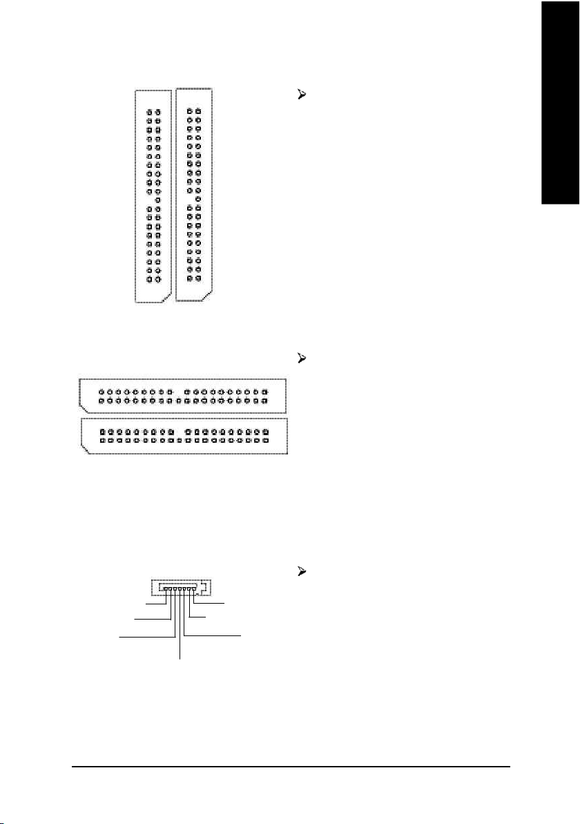
8) IDE1/ IDE2 [IDE1 / IDE2 Connector(Primary/Secondary)]
Important Notice:
Please connect first harddisk to IDE1 and
connect CDROM to IDE2.
The red stripe of the ribbon cablemust be the
same side with the Pin1.
English
IDE2
1
IDE1
1
9) IDE3 / IDE4 (RAID/ATA133, Green Connector)
IDE4
1
1
IDE3
Important Notice:
The red stripe of the ribbon cable must be the
same side with the Pin1.
If you wish to use IDE3 and IDE4, please use
it in unity with BIOS (either RAID or ATA133).
Then, install the correct driver to have proper
operation. For details, please refer to the ITE
RAID manual.
10) S_ATA1/S_ATA2 (Serial ATA Connector)
You can connect the Serial ATA device to this
7
GND
RXP
RXN
1
TXP
GND
connector, it provides you high speed transfer
rates (150MB/sec).
TXN
GND
- 21 - Hardware Installation Proc ess
11) LED Do not remove memory modules while LED is
English
12) PWR_LED
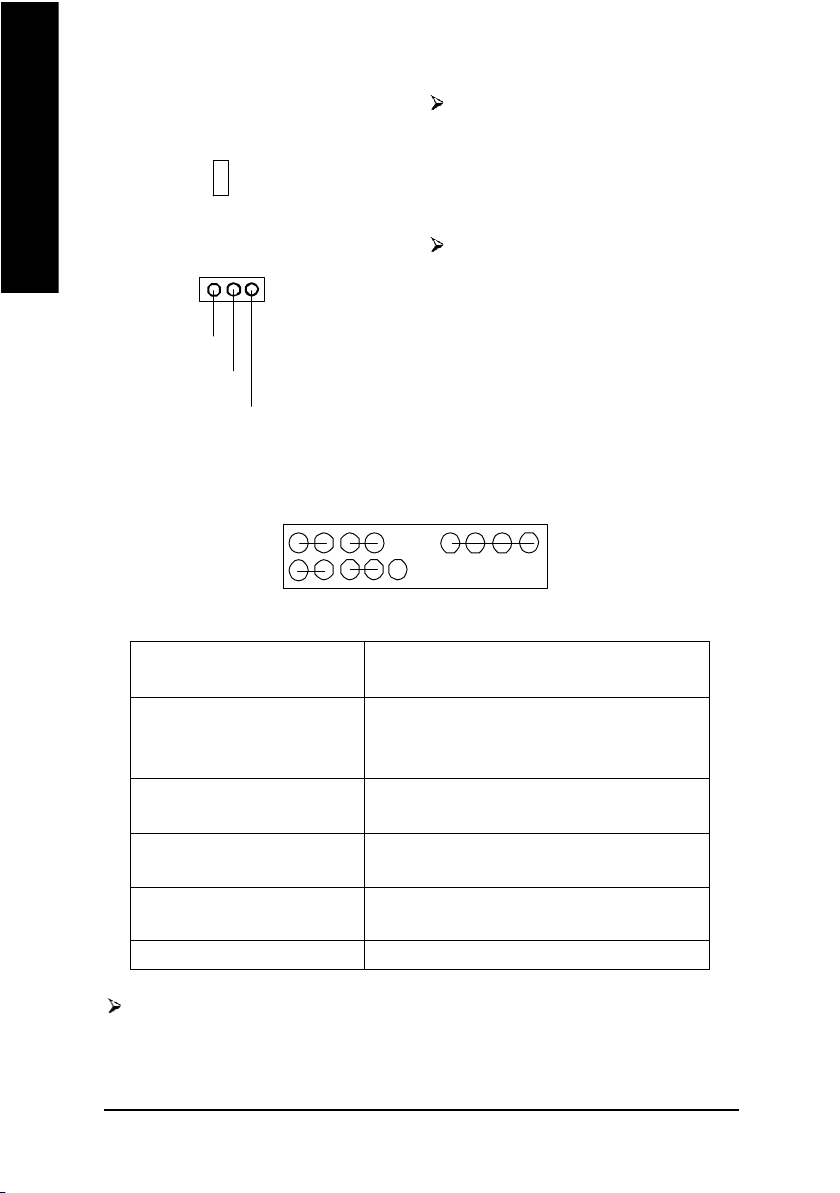
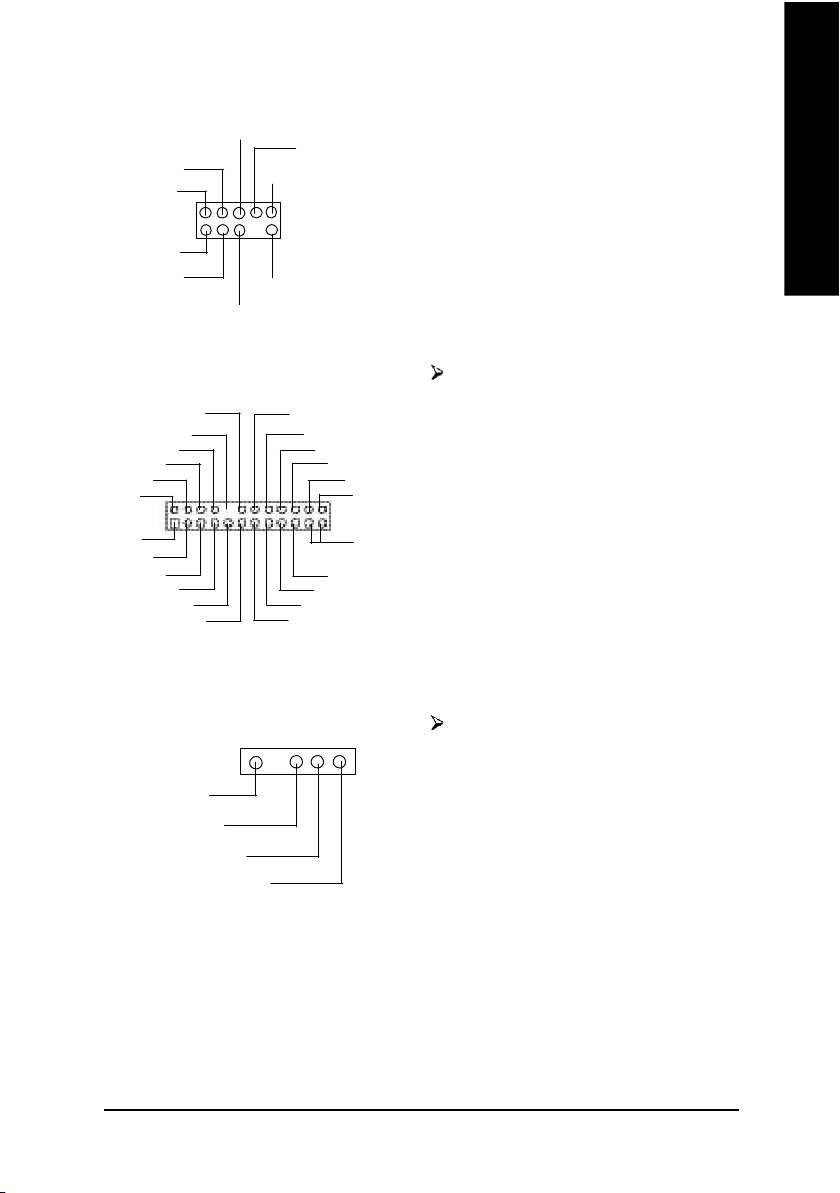
13) F_PANEL (2x10 pins connector)
1
MPD+
MPD-
-
+
on. It might cause short or other unexpected
damages due to the 2.5V stand by voltage.
Remove memory modules only when system
is power off.
PWR_LED is connect with the system power
indicator to indicate whether the system is
on/off. It will blink when the system enters
suspend mode.
If you use dual color LED, power LED will turn
to another color.
MPD-
MSG+
1
2
1
1 19
HD+
HD (IDE Hard Disk Active LED) Pin 1: LED anode(+)
(Blue) Pin 2: LED cathode(-)
SPK (Speaker Connector) Pin 1: VCC(+)
(Amber) Pin 2- Pin 3: NC
RES (Reset Switch) Open: Normal Operation
(Green) Close: Reset Hardware System
PW (Soft Power Connector) Open: Normal Operation
(Red) Close: Power On/Off
MSG(Message LED/Power/ Pin 1: LED anode(+)
Sleep LED)(Yellow) Pin 2: LED cathode(-)
NC(Purple) N C
Please connect the power LED, PC speaker, reset switch and power switch etc of your chassis
front panel to the F_PANEL connector according to the pin assignment above.
MSG-
HD-
RES-
PW-
PW+
1
1
NC
RES+
Pin 4: Data(-)
1
SPK+
SPK-
20
- 22 -GA-SINXP1394 Motherboard
14) BAT (Battery)
CAUTION
Danger of explosion if battery is incorrectly
replaced.
Replace only with the same or equivalent
+
type recommended by the manufacturer.
Dispose of used batteries according to the
manufacturer's instructions.
If you want to erase CMOS...
1.Turn OFF the computer and unplug the power
cord.
2.Remove the battery, wait for 30 second.
3.Re-install the battery.
4.Plug the power cord and turn ON the
computer.
English
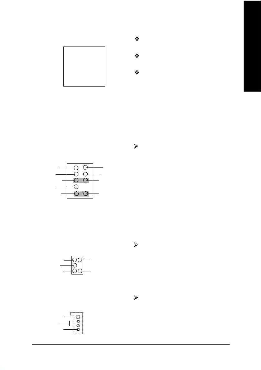
15) F_AUDIO (Front Audio Connector)
2
1
MIC
REF
Front Audio (R)
Reserved
Front Audio (L)
10
9
GND
POWER
Rear Audio (R)
Rear Audio (L)
16) SUR_CEN
1
SUR OUTL
GND
CENTER_OUT
SUR OUTR
BASS_OUT
17) CD_IN (CD Audio Line In)
CD-L
GND
CD-R
1
If you want to use "Front Audio" connector,
you must remove 5-6, 9-10 Jumper. In order to
utilize the front audio header, your chassis must
have front audio connector. Also please make
sure the pin assigment on the cable is the same
as the pin assigment on the MB header. To find
out if the chassis you are buying support front
audio connector, please contact your dealer.
Please note, you can have the of using front
audio connector or of using rear audio connector
to play sound.
Please contact your nearest dealer for optional
SUR_CEN cable.
Connect CD-ROM or DVD-ROM audio out
to the connector.
- 23 - Hardware Installation Proc ess
18) AUX_IN (AUX In Connector) Connect other device(such as PCI TV Tunner
audio out )to the connector.
English
19) SPDIF_O (SPDIF Out)
20) SPDIF_IN (SPDIF In)
21) F_USB1/F_USB2 (Front USB Connector)
USB Dy-
Power
AUX-L
GND
AUX-R
VCC
USB Dy+
1
SPDIF Out
1
SPDIF IN
GND
GNDVCC
GND
1
The SPDIF output is capable of providing
digital audio to external speakers or com
pressed AC3 data to an external Dolby
Digital Decoder. Use this feature only when
your stereo system has digital input
function.
Use this feature only when your device has
digital output function.
Be careful with the polarity of the front USB
connector. Check the pin assignment while you
N C
connect the front USB cable.
Please contact your nearest dealer for optional
front USB cable.
1
Power
USB Dx-
GND
USB Dx+
- 24 -GA-SINXP1394 Motherboard
22) SMB_CONN
GP IO
VCC
1
SMBCLK
SMBDATA
English
GND
N C
+12V
+12V
GND
23) 1394 (IEEE1394 Connector)
LINKON
GND
+12V
+12V
GND
LREQ
CTL1
N C
D0
1
LPS
D4
CTL0
D2
D5
D1
SYSC LK
D6
D3
D7
24) IR (IR Connector)
1
VCC(+5V)
IR Data Input
GND
IR Data Output
Please Note: Serial interface standard set by
Institute of Electrical and Electronics Engineers,
which has features like high speed, high band-
width and hot plug.
GND
3VDUAL
3VDUAL
GND
Be careful with the polarity of the IR
connector while you connect the IR. Please
contact you nearest dealer for optional IR
device.
- 25 - Hardware Installation Proc ess
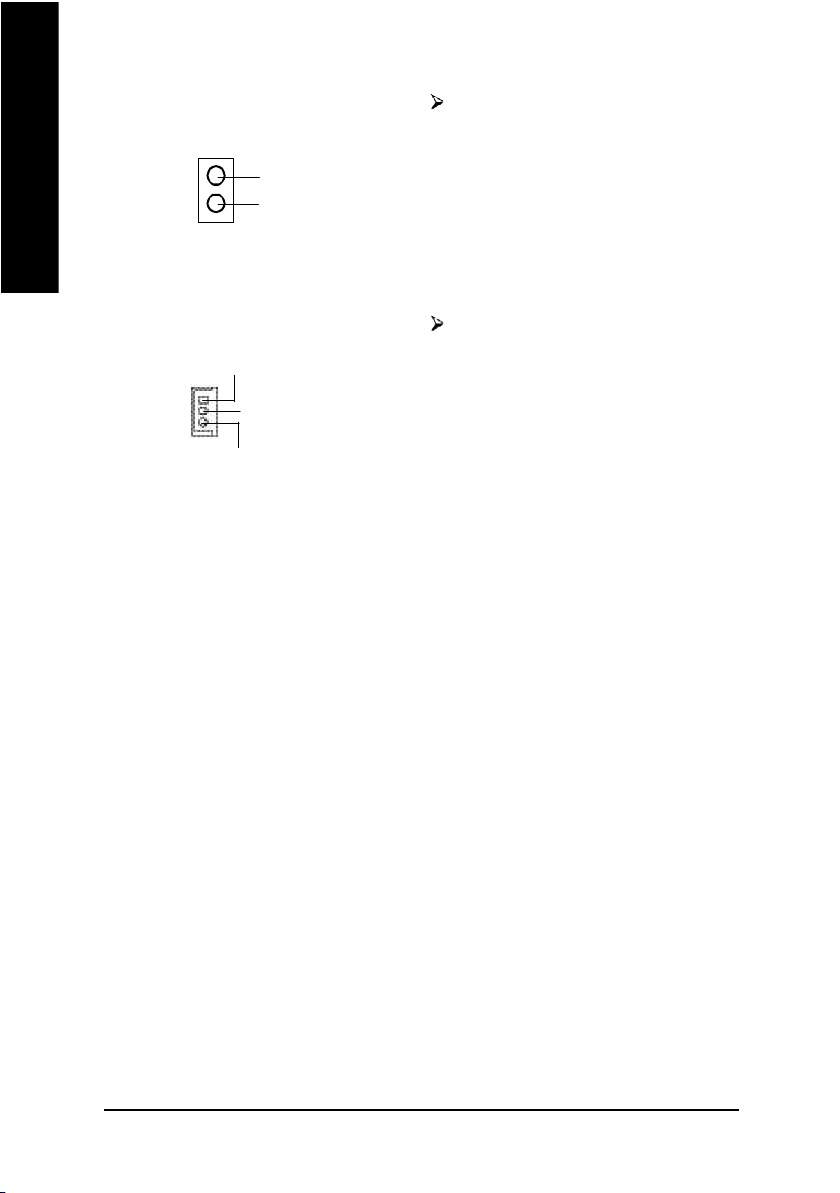
25) CI (CASE OPEN)
English
This 2 pin connector allows your system to
enable or disable the "Case Open" item in BIOS
1
Signal
GND
if the system case begin remove.
26) WOL (Wake on LAN)
+5V SB
1
GND
Signal
This connector allows the remove servers to
manage the system that installed this
mainboard via your network adapter which
also supports WOL.
- 26 -GA-SINXP1394 Motherboard
 Loading...