

Gigabyte GA-8SMML User Manual
M The author assumes no responsibility for any errors
or omissions that may appear in this document nor
does the author make a commitment to up
date the information contained herein.
M Third-party brands and names are the property of
their respective owners.
M Please do not remove any labels on motherboard, this
may void the warranty of this motherboard.
M Due to rapid change in technology, some of the
specifications might be out of date before publication
of this booklet.

Ausschlager Weg 41, 1F, 20537 Hamburg, Germany
( description of the apparatus, system, installation to whic h it refers)
(reference to the specification under which conformity is declared)
in accordance with 89/336 EEC-EMC Directive
o EN 55011 Limits a nd methods of measurement
o EN 55013
o EN 55014 Limits a nd methods of measurement
o EN 55015 Limits a nd methods of measurement
o EN 55020
T EN 55022 Limits a nd methods of measurement
o DIN VDE 0855
o part 10
o part 12
T CE marking
o EN 60065
o EN 60335
of radio d isturbance characteristics of
industrial,scientific and medical (ISM
high frequency equipment
Limits a nd methods of measurement
of radio d isturbance characteristics of
broadcast receive rs and associated
equipment
of radio d isturbance characteristics of
household electrical appliances,
portable tools and similar electrical
appa ratus
of radio d isturbance characteristics of
fluorescent lamp s and luminaries
Immuni ty from radio interference of
broadcast receive rs and associated
equipment
of radio d isturbance characteristics of
information tech nology equipment
Cabled distribution systems; Equipment
for re ceiving and/or distribution from
sound and television signals
The manufacturer also declares the conformity of above mentioned product
with the a ctual required safety standards in accordance with LVD 73/23 EEC
Safety requirements for mains o perated
electronic and rel ated apparatus for
household and similar general use
Safety of house hold and similar
electrical appliances
(S ta mp )
Declaration of Conformity
We, Manufacturer/Importer
(full address)
G.B.T. Technology Träding GMbH
declar e that the product
Mother Board
GA-8 SMML
is in conformity with
o EN 61000-3-2*
T EN 60555-2
o EN 61000-3-3* Disturban ces in supply systems cause
T EN 60555-3
T EN 50081-1 Generic emission standard Part 1:
T EN 50082-1
o EN 55081-2
o EN 55082-2
o ENV 55104
o EN50091-2
(EC co nformity marking)
o EN 60950
o EN 50091-1
Manufacturer/Impor ter
Date : Jan . 24, 2002
Disturban ces in supply systems cause
by household appliances and similar
electrical equipment “Ha rmonics”
by household appliances and similar
electri cal equipment “Voltage fluctuations”
Residual commercial and light industry
Generic immunity standard Part 1:
Residual commercial and light industry
Generic emission standard Part 2:
Industrial environment
Generic emission standard Part 2:
Industrial environment
lmmunity requirements for household
appliances tools an d similar apparatus
EMC requirements for uninterruptible
power systems (UPS)
Signa ture:
Na me:
Timmy Huang
Timmy Huang

DECLARATION OF CONFORMITY
Pe r FCC Part 2 Section 2.1077(a)
Re sponsible Party Name:
Ad dress:
Phone/Fax No:
hereby declares that the product
Pr oduct Name:
M odel Number :
Conform s to the follo wing specifications:
FCC Part 15, Sub part B, Section 15.107(a) and Section 15.109
(a),Class B Digital Device
Supplementary Information:
This device complies with part 15 of the FCC Rules. Operation is
subject to the follo wing two conditions: (1) This device may not
cause harmful and (2) this device must accept any inference received,
including that may cause undesired operation.
Representative Person’s Name:
Signature:
G .B.T. INC. (U.S.A.)
17358 Railroad Street
City of Industry, CA 91 748
(818) 854-9338/ (818) 854-9339
Motherboard
GA-8S MML
ERIC LU
Eric Lu
Dat e:
Ja n. 24,2002

GA-8SMML
P4 Titan-SDRAM Motherboard
USER’S MANUAL
Pentium®4 Processor Motherboard
Rev. 2001
12ME-8SMML-2001

English
Item Checklist .................................................................................. 4
WARNING!.......................................................................................4
Chapter 1 Introduction .......................................................................5
Chapter 2 Hardware Installation Process ............................................8
Table of Content
Features Summary................................................................................................5
GA -8SMML Motherboard Layout .......................................................................7
Step 1: Install the Central Processing Unit (CPU)...........................................9
Step 1-1 : CPU Installation........................................................................9
Step 1-2 : CPU Heat Sink Installation......................................................10
Step 2: Install memory modules .......................................................................11
Step 3: Install expansion cards.........................................................................12
Step 4: Connect ribbon cables, cabinet wires, and power supply.............13
Step 4-1 : I/O Back Panel Introduction ....................................................13
Step 4-2 : Connectors Introduction .........................................................15
Chapter 3 BIOS Setup ....................................................................22
T he Main Menu (For example: BIOS Ver. :F1)..............................................23
Standard CMOS Features.................................................................................25
BIOS Features Setup..........................................................................................28
Chipset Features Setup......................................................................................30
Power Management Setup................................................................................34
PnP/PCI Configuration........................................................................................36
- 2 -GA-8SMML Motherboard

Load Fail-Safe Defaults......................................................................................38
Load Optimized Defaults....................................................................................39
Integrated Peripherals .......................................................................................40
Haedware Monitor & MISC Setup ....................................................................46
Set Superv isor/User Password..........................................................................48
IDE HDD A uto-Detection ....................................................................................49
Sav e & Exit Setup.................................................................................................50
Exit Without Sav ing.............................................................................................51
Chapter 4 Technical Reference........................................................52
Block Diagram .....................................................................................................52
Q-Flash Introduction...........................................................................................53
@ BIOS Introduction ...........................................................................................55
Easy Tune III.........................................................................................................56
Chapter 5 Appendix .......................................................................57
English
- 3 -
Table of Content

Item Checklist
þ The GA-8SMML motherboard
English
þ IDE cable x 1/ Floppy cable x 1
þ CD for motherboard driver & utility (TUCD)
þ GA-8SMML user’s manual
Computer motherboards and expansion cards contain very delicate Integrated Circuit (IC) chips. To
protect them against damage from static electricity, you should follow some precautions whenever you
work on your computer.
W ARNING!
1. Unplug your computer when working on the inside.
2. Use a grounded wrist strap before handling computer components. If you do not have
one, touch both of your hands to a safely grounded object or to a metal object, such as
the power supply case.
3. Hold components by the edges and try not touch the IC chips, leads or connectors, or
other components.
4. Place components on a grounded antistatic pad or on the bag that came with the
components whenever the components are separated from the system.
5. Ensure that the ATX power supply is switched off before you plug in or remove the ATX
power connector on the motherboard.
Installing the motherboard to the chassis…
If the motherboard has mounting holes, but they don ’t line up with the holes on the base and there are
no slots to attach the spacers, do not become alarmed you can still attach the spacers to the mounting
holes. Just cut the bottom portion of the spacers (the spacer may be a little hard to cut off, so be careful
of your hands). In this way you can still attach the motherboard to the base without worrying about short
circuits. Sometimes you may need to use the plastic springs to isolate the screw from the motherboard
PCB surface, because the circuit wire may be near by the hole. Be careful, don’t let the screw contact
any printed circuit write or parts on the PCB that are near the fixing hole, otherwise it may damage the
board or cause board malfunctioning.
- 4 -GA-8SMML Motherboard

Chapter 1 Introduction
Features Summary
Form Factor — 22.9cm x 24.3cm Micro ATX size form factor, 4 layers PCB.
CPU — Socket 478 for Intel® Micro FC-PGA2 Pentium® 4 processor
— Support Intel ® Pentium ® 4 (Northwood, 0.13 m) processor
— Intel Pentium®4 400MHz FSB
— 2nd cache depend on CPU
Chipset — SiS 650 Host/Memory controller(**)
— SiS 650GX Host/Memory controller(*)
— SiS 961 MuTIOL Media I/O
Memory — 3 168-pin DIMM sockets
— Supports PC-100/PC-133 SDRAM (Auto)
— Supports only 3.3V SDRAM DIMM
— No Regisitered DIMM support
— Supports up to 3GB SDRAM (Max)
I/O Control — W83697HF
Slots — 1 Universal AGP slot (1X/2X/4X) device support
— 3 PCI slot supports 33MHz & PCI 2.2 compliant
— 1 CNR(Communication and Networking Riser) Slot
On-Board IDE — 2 IDE bus maste r (UDMA33/ATA66/ATA100) IDE po rts for up to 4
ATAPI devices
— Supports PIO mode3,4 (UDMA 33/ATA66/ATA100) IDE & ATAPI
CD-ROM
On-Board Peripherals — 1 Floppy port supports 2 FDD with 360K, 720K,1.2M, 1.44M
and 2.88M bytes.
— 1 Parallel port supports Normal/EPP/ECP mode
— 2 Serial ports (COMA&VGA),COMB on board
— 1 Front Audio Connector
— 1 Serial IRQ Connector**
— 1 IrDA connector for IR**
to be continued......
English
*For PCB 2.0 ver only
**For PCB 1.0 ver only
- 5 -
Introduction

Hardware Monitor — CPU/System Fan Revolution detect
English
On-Board Sound — Sigmatel 9721 CODEC
On-Board LAN — Builit in RTL8100 Chipset
On-Board VGA — Builit in SiS650 Chipset(**)
PS/2 Connector — PS/2 Keyboard interface and PS/2 Mouse interace
BIOS — Licensed AMI BIOS, 2M bit Flash ROM
Additional Features — PS/2 Keyboard power on by password
— CPU/System Fan Control
— CPU Overheat Warning
— System Voltage Detect
— Line In/Line Out/Mic In/CD In/AUX In*/Game Port
— 1 RJ45 port
— Builit in SiS650GX Chipset(*)
— PS/2 Mouse power on
— STR(Suspend-To-RAM)
— AC Recovery
— USB KB/Mouse wake up from S3
— Supports EasyTuneIII
— Supports @BIOS
Please set the CPU host frequency in accordance with your processor’s specifications.
We don’t recommend you to set the system bus frequency over the CPU’s specification
because these specific bus frequencies are not the standard specifications for CPU,
chipset and most of the peripherals. Whether your system can run under these specific
bus frequencies properly will depend on your hardware configurations, including CPU,
Chipsets,SDRAM,Cards… .etc.
*For PCB 2.0 ver only
**For PCB 1.0 ver only
- 6 -GA-8SMML Motherboard

GA-8SMML Motherboard Layout
English
KB_MS
COMA
VGA
LINE_OUT
LINE_IN
MIC_IN
AC97
USB/
LPT
GAME
BIOS
LAN
CD_IN
AUX_IN*
W83697HF
RTL8100
S_IRQ**
BIOS_WP*
ATX_12V
F-AUDIO
SiS 650(**)
SiS650GX(*)
CNR
SOCKET478
GA-8SMML
PCI1
PCI2
BATTERY
PCI3
COMB
AGP
F_USB
CPU_FAN
DIMM1
DIMM2
SiS 961
F_P ANEL
DIMM3
DIMM_LED
IDE1
IDE2
CI
Buzzer
ATX
FDD
IR**
CLR_CMOS***
SYS _FAN
*For PCB 2.0 ver only
**For PCB 1.0 ver only
- 7 -
Introduction

Chapter 2 Hardware Installation Process
To set up your computer, you must complete the following steps:
English
Step 1- Install the Central Processing Unit (CPU)
Step 2- Install memory modules
Step 3- Install expansion cards
Step 4- Connect ribbon cables, cabinet wires, and power supply
Step 5- Setup BIOS software
Step 6- Install supporting software tools
Step1
Step4
Step 2
Step 4
Step3
Step 4
- 8 -GA-8SMML Motherboard

Step 1: Install the Central Processing Unit (CPU)
Step 1-1 : CPU Installation
English
Pin1 indicator
CPU Top View CPU Bottom View
Socket Actuation Lever
1. Pull up the CPU socket lever
and up to 90-degree angle.
3. Press down the CPU socket
lever and finish CPU installation.
M Please make sure the CPU type is supported by the motherboard.
M If you do not match the CPU socket Pin 1 and CPU cut edge well, it will cause
improper installation. Please change the insert orientation.
Pin1 indicator
Pin1 indicator
2. Locate Pin 1 in the socket and look
for a (golden) cut edge on the CPU
upper corner. Then insert the CPU
into the socket.
- 9 - Hardw are Installation Process

Step 1-1 :CPU Heat Sink
Installation
English
1. Hook one end of the cooler
bracket to the CPU socket first.
M Please use Intel approved cooling fan.
M We recommend you to apply the thermal tape to provide better heat
conduction between your CPU and heatsink.
(The CPU cooling fan might stick to the CPU due to the hardening of the
thermal paste. During this condition if you try to remove the cooling fan, you
might pull the processor out of the CPU socket alone with the cooling fan, and
might damage the pr ocessor. To avoid this from happening, we suggest you to
either use thermal tape instead of therm al paste, or remove the cooling fan with
extreme caution.)
M Make sure the CPU fan power cable is plugged in to the CPU fan connector,
this completes the installation.
M Please refer to CPU heat sink user’s manual for more detail installation
procedure.
2. Hook the other end of the
cooler bracket to the CPU
socket.
- 10 -GA-8SMML Motherboard
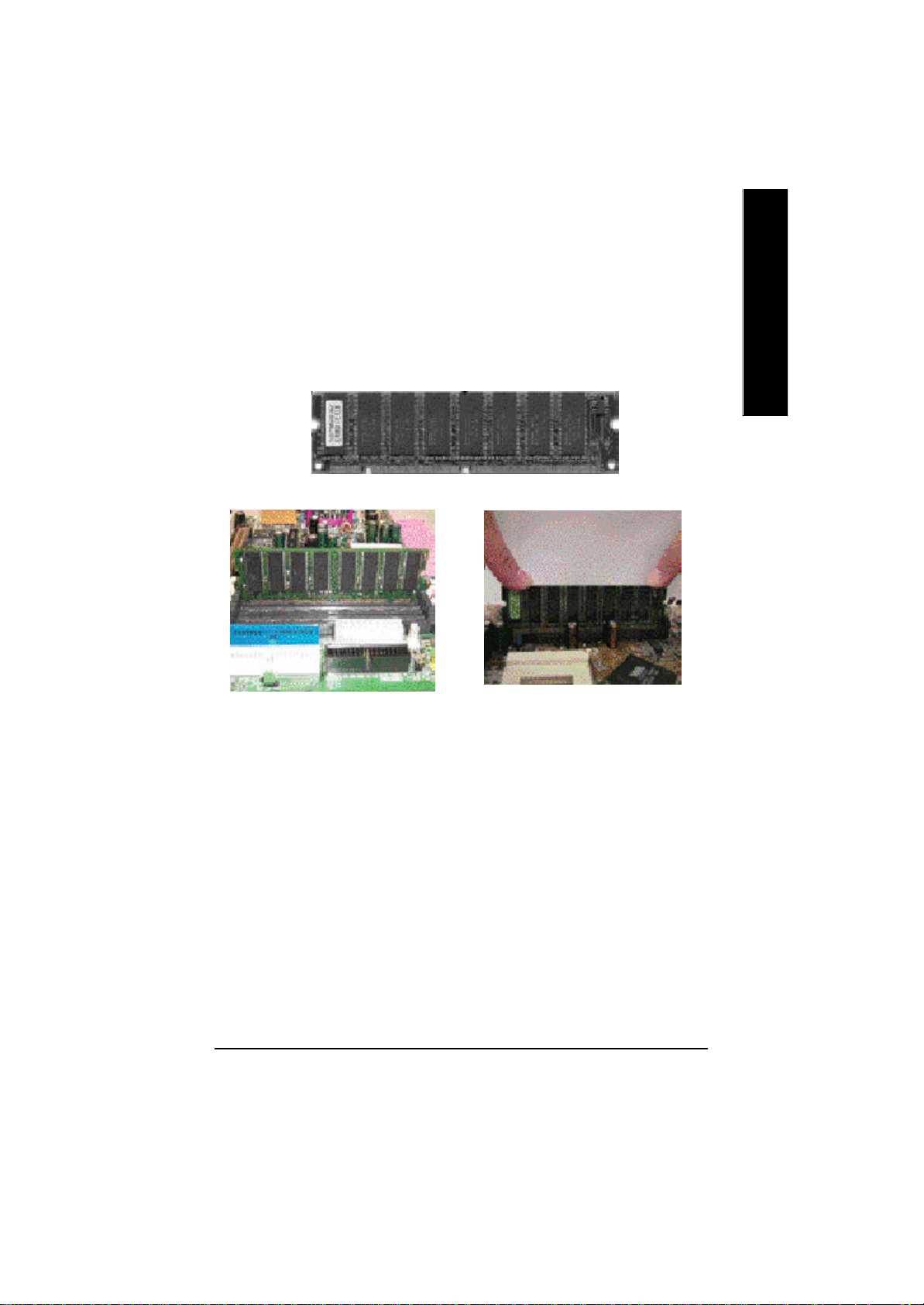
Step 2: Install memory modules
The motherboard has 3 dual in-line memory module (DIMM) sockets. The BI OS will automatically
detects memory type and size. To install the memory module, just push it vertically into the DIMM Slot
.The DIMM module can only fit in one direction due to the two notch. Memory size can v ary between
sockets.
SDRAM
English
1. The DIMM slot has two notch, so the
DIMM memory module can only fit in
one direction.
3. Close the plastic clip at both edges of the DIMM slots to lock the DIMM module.
Reverse the installation steps when you wish to remove the DIMM module.
2. Insert the DIMM memory module
vertically into the DIMM slot. Then
push it down.
M Please note that the DIMM module can only fit in one direction due to the one
notches. Wrong orientation will cause improper installation. Please change
the insert orientation.
- 11 - Hardw are Installation Process

Step 3: Install expansion cards
1. Read the related expansion card’s instruction document before install the expansion card into
English
2. Remove your computer’s chassis cover, necessary screws and slot bracket from the computer.
3. Press the expansion card firmly into expansion slot in motherboard.
4. Be sure the metal contacts on the card are indeed seated in the slot.
5. Replace the screw to secure the slot bracket of the expansion card.
6. Replace your computer’s chassis cover.
7. Power on the computer, if necessary, setup BIOS utility of expansion card from BIOS.
8. Install related driver from the operating system.
the computer.
AGP Card
Please carefully pull out the small whitedrawable bar at the end of the AGP slot when
you try to install/ Uninstall the AGP card.
Please align the AGP card to the onboard
AGP slot and press firmly down on the slot .
Make sure your AGP card is locked by the
small white- drawable bar.
- 12 -GA-8SMML Motherboard

Step 4: Connect ribbon cables, cabinet wires, and power
supply
Step4-1:I/O Back Panel Introduction
English
v w
u
u PS/2 Keyboard and PS/2 Mouse Connector
PS/2 Mouse Connector
(6 pin Female)
PS/2 Keyboard Connector
(6 pin Female)
v USB & LAN Connector
LAN
USB 0
USB 1
ØThis connector supports standard PS/2 keyboard
and PS/2 mouse.
ØBefore you connect your device(s) into USB
connector(s), please make sure your device(s)
such as USB keyboard,mouse, scanner, zip,
spea ker..etc. Have a standard USB interface. Also
make sure your OS (Win 95 with USB supplement,
Win98, Windows 2000, Windows ME, Win NT
with SP 6) supports USB controller. If your OS
does not support USB controller, please contact
OS vendor for possible patch or driver upgrade.
For more information please contact your OS or
device(s) vendors.
x
y
- 13 - Hardw are Installation Process
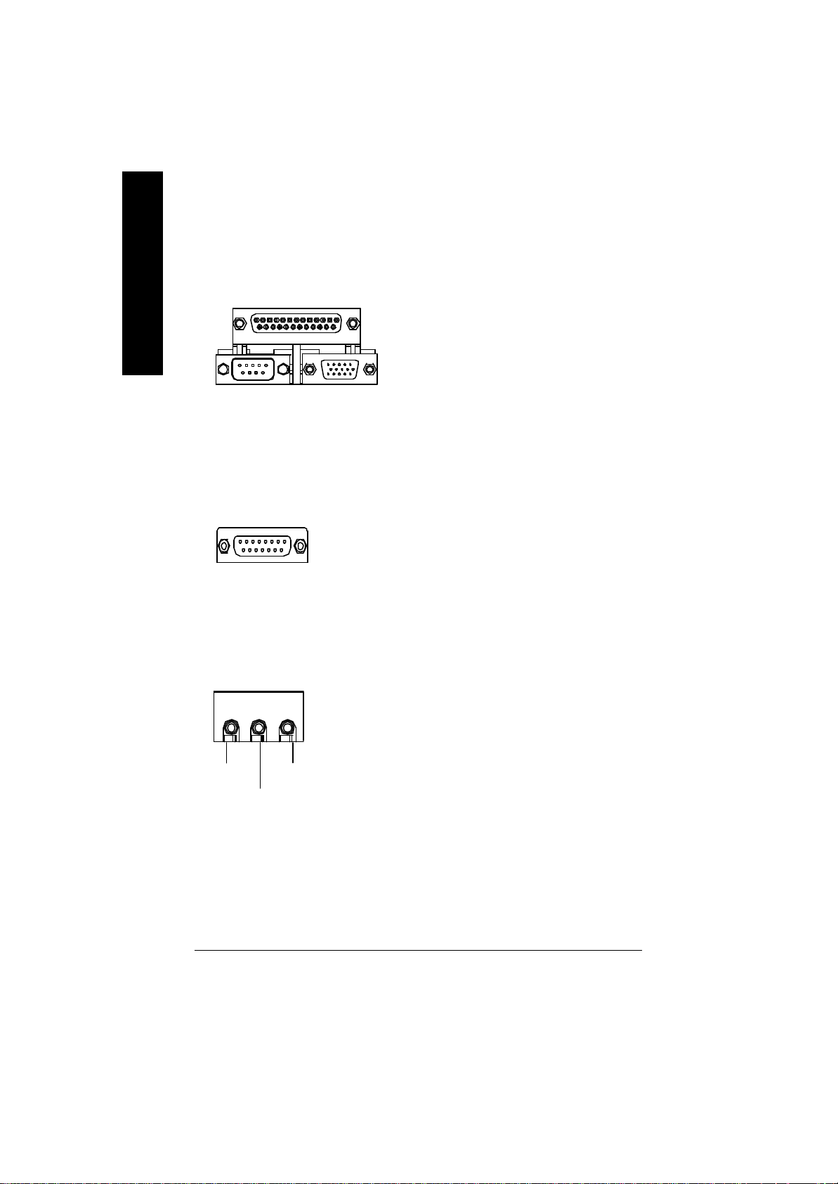
w Parallel Port , Serial Port and VGA Port (LPT/COMA/VGA)
English
Parallel Port
(25 pin Female)
COMA VGA
Serial Port
(9 pin Male)
VGA Port
(15 pin Female)
ØThis connector supports 1 standard COM port
,1 Parallel port and 1 VGA port. Device like
printercan be connected to Parallel port ; mouse
and modem etc can be connected to Serial ports.
x Game /MIDI Ports
Joystick/ MIDI (15 pin Female)
y Audio Connectors
Line Out
MIC In
Line In
ØThis connector supports joystick, MIDI keyboard
and other relate audio devices.
Ø After install onboard audio driver, you may
connect speaker to Line Out jack, micro phone to
MIC In jack. Device like CD-ROM , walkman etc
can be connected to Line-In jack.
- 14 -GA-8SMML Motherboard

Connectors Introduction
English
A B
C
R
Q
P
O
N
A) ATX_12V
B) CPU_FAN
C) ATX
D) FLOPPY
E) IDE1/IDE2
F) IR **
G) CLR_CMOS *
H) SYS_FAN
I) CI
L
JKM
J) F_P ANEL
K) F_USB
L) BATTERY
M) COMB
N) BIOS_WP *
O) S_IRQ **
P) AUX_IN *
Q) CD_IN
R) F_AUDIO
D
E
F
G
H
I
*For PCB 2.0 ver only
**For PCB 1.0 ver only
- 15 - Hardw are Installation Process

A) ATX_12V ( +12V Power Connector)
English
GND
GND
123
ØThis connector (ATX +12V) suppliesthe CPU
operation voltage (Vcore).
If this " ATX+ 12V connector" is not connected,
system cannot boot.
+12V
+12V
4
B ) CPU_FAN (CPU FAN Connector)
1
GND
+12V/Control
Sense
H ) SYS_FAN (System FAN Connector)
Sense
1
+12V/Control
GND
I) CI (CASE OPEN)
Signal
GND
Ø Please note, a proper installation of the CPU
cooler is essential to prevent the CPU from
running under abnormal condition or damaged
by overheating.The CPU fan connector
supports Max. current up to 600 mA.
Ø This 2 pin connector allows your system to
enable or disable the system alarm if the sys
tem case begin remove.
1
- 16 -GA-8SMML Motherboard

D) FDD (Floppy Connector)
1
English
E) IDE1/ IDE2 (IDE1/IDE2 Connector)
1
IDE1
1
IDE2
M) COM B
NCTSB-
NSINB
NDTRB-
NDSRB-
NC
Ø Important Notice:
Please connect first harddisk to IDE1
and connect CDROM to IDE2.
1
GND
NDCDB-
NSOUTB
NRIB-
NRTSB-
- 17 - Hardw are Installation Process

Q) CD_IN (CD Audio Line In)
English
P) AUX_IN ( AUX In Connector)*
CD-R
GND
1
1
CD-L
AUX-R
GND
AUX-L
R) F_AUDIO (Front Audio Connector)
GND
MIC
Front Audio (L)
Front Audio (R)
1
GND
Rear Audio (L)
Rear Audio (R)
Ø If you want to use "Front Audio" connector,
you must move 3-4,5-6 Jumper. In order to
utilize the front audio header, your chassis must
have front audio connector. Also please make
sure the pin assigment on the cable is the same
as the pin assigment on the MB header. To find
out if the chassis you are buying support front
audio connector, please contact your dealer.
*For PCB 2.0 ver only
**For PCB 1.0 ver only
- 18 -GA-8SMML Motherboard

C ) ATX (ATX Power)
5V SB (Stand by +5V)
+12V
Power Good
GND
VCC
GND
VCC
GND
3.3V
3.3V
Ø AC power cord should only be connected to
20
VCC
VCC
-5V
GND
GND
GND
PS-ON(Soft On/Off)
GND
-12V
1
3.3V
your power supply unit after ATX power cable
and other related devices are firmly
connected to the mainboard.
English
K) F_USB (Front USB Connector)
GND
USB 3+
USB 3-
Power
1
USB 2-
USB 2+
GND
Power
F)IR **
1
VCC(+5V)
IR Data Input
GND
IR Data Output
Ø Be careful with the polarity of the front
panel USB connector. Check the pin
assignment while you connect the front
panel USB cable. Please contact your
nearest dealer for optional front panel
USB cable.
Ø Be careful with the polarity of the IR
connectorwhile you connect the IR. Please
contact you nearest dealer for optional IR
device.
*For PCB 2.0 ver only
**For PCB 1.0 ver only
- 19 - Hardw are Installation Process

N) BIOS_WP*
(BIOS Write Protection)
English
1
1
2-3 close: Normal
1-2 close: Write Protection
Ø Please note, To flash/upgrade BIOS on this MB
BIOS_WP must be set to 2-3 close. We
recommend BIOS_WP to be set to "1-2 close",
whenever user does not need to flash/upgrade
the BIOS.
G) CLR_CMOS*
(Clear CMOS)
1
2-3 close: Normal
1
1-2 close: Clear CMOS
Ø You may clear the CMOS data to its default
values by this jumper.
M) S_IRQ **
(For special design, for example: PCMCIA add on card)
Signal
GND
1
*For PCB 2.0 ver only
**For PCB 1.0 ver only
- 20 -GA-8SMML Motherboard

J) F_P ANEL (2x7 pins jumper)
RST+
RST-
PD+
PD_G-
SPK+
1
PW-
13
PW+
Pin 2: LED cathode(-)
Pin 2- Pin 3: NC
Pin 4: Data(-)
Close: Reset Hardware System
Pin 2: LED cathode(-)
Pin 3: LED cathode(-)
Close: Power On/Off
SPK-
HD-
2 14
1
1
PD_Y-
HD+
HD (IDE Hard Disk Active LED) Pin 1: LED anode(+)
SPK (Speaker Connector) Pin 1: VCC(+)
RST (Reset Switch) Open: Normal Operation
PD+/PD_G-/PD_Y-(Power LED) Pin 1: LED anode(+)
PW (Soft Power Connector) Open: Normal Operation
English
Ø Please connect the power LED, PC speaker, reset switch and power switch etc of your chassis
front panel to the F_PANEL connector according to the pin assignment above.
L) Battery
v Danger of explosion if battery is incorrectly
+
replaced.
v Replace only with the same or equivalent
type recommended by the manufacturer.
v Dispose of used batteries according to the
manufacturer’s instructions.
- 21 - Hardw are Installation Process
CAUTION

Chapter 3 BIOS Setup
BIOS Setup is an overview of the BIOS Setup Program. The program that allows users to modify the
English
basic system configuration. This type of information is stored in battery-backed CMOS RAM so that it
retains the Setup information when the power is turned off.
ENTERING SETUP
Power ON the computer and press <Del> immediately will allow you to enter Setup. If the message
disappe ars before you respond and you still wish to enter Setup, restart the system to try again by turning
it OFF then ON or pressing the “RESET” bottom on the system case. You may also restart by
simultaneously press <Ctrl> - <Alt>- <Del> keys.
CONTROL KEYS
<á> Move to previous item
<â> Move to next item
<ß> Move to the item in the left hand
<à> Move to the item in the right hand
<Esc> Main Menu - Quit and not save changes into CMOS Status Page Setup Menu and
<+/PgUp> Increase the numeric value or make changes
<-/PgDn> Decrease the numeric value or make changes
<F1> General help, only for Status Page Setup Menu and Option Page Setup Menu
<F2> Reserved
<F3> Reserved
<F4> Reserved
<F5> Restore the previous CMOS value from CMOS, only for Option Page Setup Menu
<F6> Load the default CMOS value from BIOS default table, only for Option Page Setup
<F7> Load the Setup Defaults
<F8> Reserved
<F9> Reserved
<F10> Save all the CMOS changes, only for Main Menu
Option Page Setup Menu - Exit current page and return to Main Menu
Menu
- 22 -GA-8SMML Motherboard
 Loading...