

Gigabyte GA-8PEMT4 User Manual [zh]
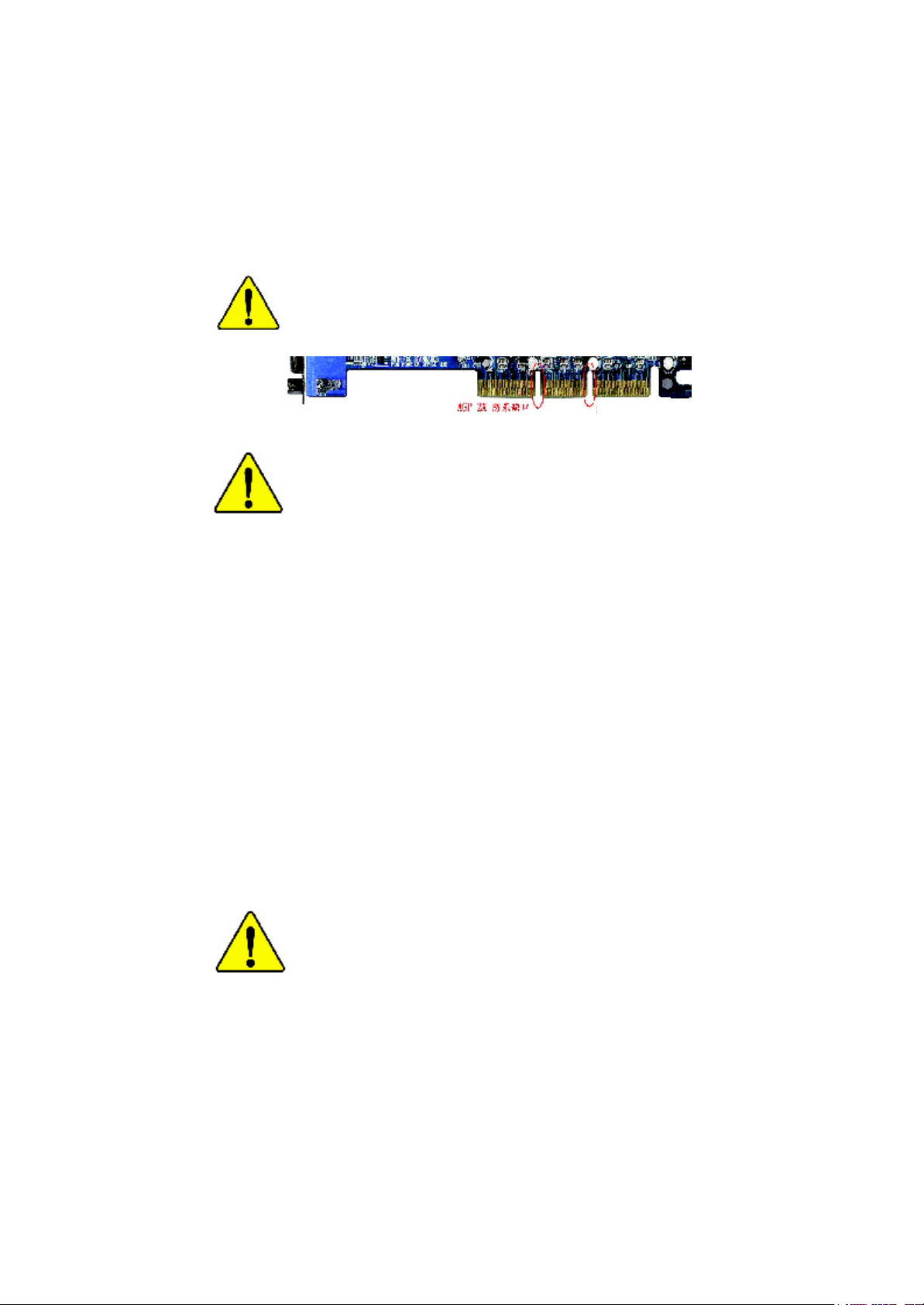
當您安裝AGP卡時,請注意下述注意事項。
您的顯示卡若有AGP 4X 防呆缺口(如下圖),請再次確認
此卡的規格為AGP 4X(1.5V)。
AGP 4X 防呆缺口
不要使用AGP 2X 卡,因為Intel® 845(GE/PE) /845(E/G) / 850
(E)晶片組不支援AGP 2X(3.3V),若您使用AGP 2X (3.3V)卡
時, 可能造成系統無法正常開機的情況,所以請使用
AGP 4X(1.5V)卡。
範例一:Diamond Vipper V770 這塊顯示卡的金手指部份設
計成2X/4X插槽皆可使用,透過Jumper可切換於2X或4X,
出廠預設值為2X(3.3V),若您使用此卡在GA-8PEMT4主機
板上,而且沒有將Jumper切換至4X
(1.5V)的模式時,可能造成系統無法正常開機的情況。
範例二:某些SiS 305及Power Color所生產的某些ATi Rage
128 Pro 等顯示卡的金手指部份設計成2X/4X插槽皆可使
用,但只支援2X(3.3V),若您使用此卡在GA-8PEMT4主機
板上,可能造成系統無法正常開機的情況。
注意:技嘉科技所生產的AG32S(G)顯示卡,雖然採用ATi
Rage 128 Pro晶片,但此卡設計符合AGP4X(1.5V)的規格,
因此不會發生如範例二中可能造成系統無法正常開機的
情況,請您安心使用。
當您在安裝PCI設備前,若有發現PCI擴充槽上有Dual BIOS
貼紙,請先移除此貼紙 .
本手冊所有提及之商標與名稱皆屬該公司所有。
在科技迅速的發展下,此發行手冊中的一些規格可能會
有過時不適用的敘述,敬請見諒。
在此不擔保本手冊無任何疏忽或錯誤亦不排除會再更新
發行。手冊若有任何內容修改,恕不另行通知。
主機板上的任何貼紙請勿自行撕毀,否則會影響到產品
保固期限的認定標準。

Ausschlager Weg 41, 1F, 20537 Hamburg, Germany
( description of the apparatus, system, installation to which it refers)
(reference to the specification under which conformity is declared)
in accordance with 89/336 EEC-EMC Directive
o EN 55011 Limits and methods of measurement
o EN 55013
o EN 55014 Limits and methods of measurement
o EN 55015 Limits and methods of measurement
o EN 55020
T EN 55022 Limits and methods of measurement
o DIN VDE 0855
o part 10
o part 12
T CE marking
o EN 60065
o EN 60335
of radio disturbance characteristics of
industrial,scientific and medical (ISM
high frequency equipment
Limits and methods of measurement
of radio disturbance characteristics of
broadcast receivers and associated
equipment
of radio disturbance characteristics of
household electrical appliances,
portable tools and similar electrical
apparatus
of radio disturbance characteristics of
fluorescent lamps and luminaries
Immunity from radio interference of
broadcast receivers and associated
equipment
of radio disturbance characteristics of
information technology equipment
Cabled distribution systems; Equipment
for receiving and/or distribution from
sound and television signals
The manufacturer also declares the conformity of above mentioned product
with the actual required safety standards in accordance with LVD 73/23 EEC
Safety requirements for mains operated
electronic and related apparatus for
household and similar general use
Safety of household and similar
electrical appliances
(S tamp )
Declaration of Conformity
We, Manufacturer/Importer
(full address)
G.B.T. Technology Träding GMbH
declare that the product
Mother Board
GA-8P EMT4
is in conformity with
o EN 61000-3-2*
T EN 60555-2
o EN 61000-3-3* Disturbances in supply systems cause
T EN 60555-3
T EN 50081-1 Generic emission standard Part 1:
T EN 50082-1
o EN 55081-2
o EN 55082-2
o ENV 55104
o EN50091-2
(EC conformity marking)
o EN 60950
o EN 50091-1
Manufacturer/Importer
Date : Nov. 15, 2002
Disturbances in supply systems cause
by household appliances and similar
electrical equipment “Harmonics”
by household appliances and similar
electrical equipment “Voltage fluctuations”
Residual commercial and light industry
Generic immunity standard Part 1:
Residual commercial and light industry
Generic emission standard Part 2:
Industrial environment
Generic emission standard Part 2:
Industrial environment
lmmunity requirements for household
appliances tools and similar apparatus
EMC requirements for uninterruptible
power systems (UPS)
Safety for information technology equipment
including electrical bussiness equipment
General and Safety requirments for
uninterruptible power systems (UPS)
Signature:
Name:
Timmy Huang
Timmy Huang
DECLARA TION OF CONFORMITY
Pe r FCC Part 2 Section 2.1077(a)
Re sponsible Party Name:
Ad dress:
Phone/Fax No:
hereby declares that the product
Pr oduct Name:
M odel Number :
Conform s to the follo wing specifications:
FCC Part 15, Sub part B, Section 15.107(a) and Section 15.109
(a),Class B Digital De vice
Sup plementary Information:
This device co mplies with part 15 of the FCC Rules . Operation is
subject to t he following two conditions: (1) This device may not
cause harmful and (2) this device must accept any inference received,
including that may cause undesired operation.
Representative Person’s Name:
Signature:
G .B.T. INC. (U.S.A.)
17358 Railroad Street
City of Industr y, CA 91748
(818) 854-9338/ (818) 854-9339
Mother board
GA-8 PEMT4
ERIC LU
Eric Lu
Dat e:
No v. 15,2002

GA-8PEMT4 系列
P4 泰坦DDR 主機板
中文安裝使用手冊
®
Pentium
4 處理器主機板
Rev. 1001
12MC-8PEMT4-1001

繁
體
中
文
目錄
清點附件.................................................................................. 4
警告標語.................................................................................. 4
第一章 序言............................................................................ 5
特色彙總................................................................................................................ 5
GA-8PEMT4 系列主機板Layout 圖 .............................................................. 7
第二章 硬體安裝步驟........................................................ 8
步驟1:安裝中央處理器(CPU) ..................................................................... 9
步驟1-1:中央處理器之安裝 ............................................................................... 9
步驟1-2::中央處理器之散熱裝置安裝 ............................................................ 10
步驟2:安裝記憶體模組............................................................................... 11
步驟3:連接所有訊號線、排線、電源供應線及面板控制線 13
步驟3-1:後方I/O 裝置鐵片介紹 ....................................................................... 13
步驟3-2:插座及跳線介紹 ................................................................................. 15
第三章BIOS 組態設定 ......................................................23
主畫面功能 (For Example BIOS Verson:F1) ............................................... 24
標準CM OS 設定 ...............................................................................................26
進階 BIOS 功能設定 ....................................................................................... 29
- 2 -GA-8PEMT4 系列主機板

繁
整合週邊設定................................................................................................... 31
省電功能設定................................................................................................... 35
隨插即用與PCI 組態設定 .......................................................................... 37
電腦健康狀態................................................................................................... 38
頻率/ 電壓控制 ................................................................................................ 40
最高效能.............................................................................................................. 42
載入 Fail-Safe 預設值...................................................................................... 43
載入Optim ized 預設值 .................................................................................... 44
設定管理者 (Supervisor)/ 使用者(User)密碼 ......................................... 45
離開SET UP 並儲存設定結果 ...................................................................46
離開SET UP 但不儲存設定結果.............................................................. 47
第四章 技術文件參考資料............................................49
晶片組功能方塊圖 ........................................................................................ 49
BIOS 更新程序................................................................................................... 50
@ BIOS
Easy Tune 4
二聲/ 四聲 / 六聲道音效功能介紹 ........................................................ 67
TM
介紹..................................................................................................... 65
TM
介紹............................................................................................. 66
體
中
文
第五章 附錄..........................................................................75
目錄- 3 -
繁
體
清點附件
中
文
þ GA-8PEMT4 主機板一片
þ 硬碟插座排線 x 1 / 軟碟插座排線 x 1
þ 主機板驅動程式光碟片
þ GA-8PEMT4 中文安裝手冊
þ 後方I/O 裝置鐵片(*)
þ Motherboard Settings 貼紙
警告標語
主機板由許多精密的積體電路及其他元件所構成,這些積體電路很容易因為遭到靜
電影響而損失。所以請在正式安裝前,做好下列準備。
1. 請將電腦的電源關閉,最好拔除電源插頭。
2. 拿取主機板時請儘量避免觸碰金屬接線部份。
3. 拿取積體電路元件(CPU 、RAM)時,最好能夠戴上有防靜電手環。
4. 在積體電路未安裝前,需將元件置放在靜電墊或防靜電袋內。
5. 當您將主機板中的 ATX電源供應器插座上的插頭拔除時,請確認電源供應器
的開關是關閉狀況。
安裝主機板至機殼中…
大多數電腦機殼的底部會有多個固定孔孔位,可使主機板確實固定並且不會短
路。請小心不要讓螺絲接觸到任何 PCB板上的線路或零件,當印刷電路主機板表面
線路接近固定孔時,您可使用塑膠墊片來讓螺絲與主機板表面隔離過,避免造成主
機板損壞或故障。
(*)只有 GA-8PEMT4 才有此功能
- 4 -GA-8PEMT4 系列主機板

第一章 序言
繁
體
特色彙總
規格 l 主機板採四層設計Micro ATX規格 22.0 公分x 24.4 公分
主機板 l GA-8PEMT4 系列主機板包括
GA-8PEMT4 及GA-8PEM T4-C
中央處理器 l Socket478 支援最新Intel Micro FC -PGA2 Pentium®4 處理器
l 支援Intel
l 支援Intel
l Intel Pentium®4 533/400MHz FSB
l 2nd 快取記憶體取決於C PU
晶片組 l Chipset 82845PE HOST/AGP/Controller
l ICH4 I/O Controller Hub
記憶體 l 2 184-pin DIMM 插槽
l 支援DDR333/DDR266 DDR DIMM
l 支援2.5V DDR DIMM
l 最高容量可擴充至2GB
I/O 控制器 l ITE8712
擴充槽 l 1 AGP 擴充槽支援4X (1.5V)裝置
l 3 PCI 擴充槽支援33M Hz 及PC I2.2 compliant
內建IDE l 2 IDE bus master (UDMA 33/ATA 66/ATA 100) IDE 埠可連接
4 ATAPI 裝置,支援PIO mode 3,4,5,U DMA33/ATA66/ATA100 IDE
及ATAPI C D-ROM
內建周邊設備 l 1 個軟碟插座支援兩台磁碟機(360K,720K,1.2M,1.44M
及2.88M by tes)
l 1 組並列埠插座可支援N ormal/EPP/EC P 模式
l 2 組串列埠插座(COMA,COMB)
l 6組USB埠插座 (2.0/1.1,後端通用串列埠 x 2, by optional cablex4)
l 1 組紅外線連接端(IR/CIR)
l 1 組M ODEN 埠插座(*)
l 1 第二組音源插座
M 因為晶片組(Intel 845PE/GE/GV) 的架構限制,FSB533 的Pntium 4 處理器可支援
DDR266 及DDR333 的記憶體模組;當使用FSB400 的Pntium 4 處理器時只能使用
DDR266 的記憶體模組.
®
®
(*)只有 GA-8PEMT4 才有此功能
®
Pentium
Pentium ® 4 Processor with HT Technology
4 (Northwood, 0.13 m) 處理器
- 5 -
續下頁.......
中
文
序言
繁
體
中
文
硬體監控 l CPU/系統風扇運轉偵測
l CPU/系統風扇控制
l CPU 溫度偵測
l 系統電壓自動偵測
內建音效晶片 l CODEC音效晶片 (RealTek ALC650)
l Line Out : 2 組前置喇叭
l Line In : 2 組後置喇叭(由軟體切換)
l Mic In : 中央聲道/ 重低音(由軟體切換)
l SPDIF out
l CD_In/AUX_In/Game Port
l 蜂鳴器
內建網路晶片(*) l 內建 RTL8101L 晶片
l 1 RJ 45 埠
PS/2 插座 l PS/2 鍵盤插座及PS/2 滑鼠插座
BIOS l 使用經授權AWARD BIOS,2M bit 快閃記憶體
l 支援Q-Flash 功能
附加特色 l PS/2 鍵盤開機
l PS/2 滑鼠開機
l 外接型數據機開機功能
l 支援STR 功能(Suspend-To-RAM)
l 網路喚醒功能
l AC Recovery
l 鍵盤過電流保護
l USB 鍵盤/ 滑鼠 w ake up from S3
l 支援@BIOS
l 支援Easy Tune 4
獨家特色 l 超時脈(CPU/DDR/AGP/PCI)
(*)只有 GA-8PEMT4 才有此功能
請依據您CP U 的規格來設定C PU 的頻率,我們不建議您將系統速度設定超
過硬體之標準範圍, 因為這些規格對於周邊設備而言並不算是符合標準規
格。如果您要將系統速度設定超出標準規格 , 請評估您的硬體規格設定, 例
如;CPU,顯示卡, 記憶體,硬碟來設定.
- 6 -GA-8PEMT4 系列主機板
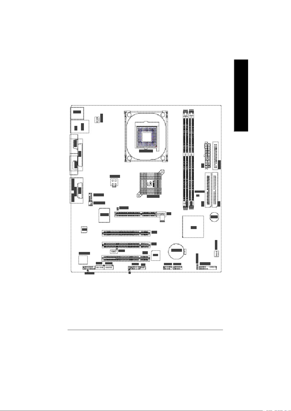
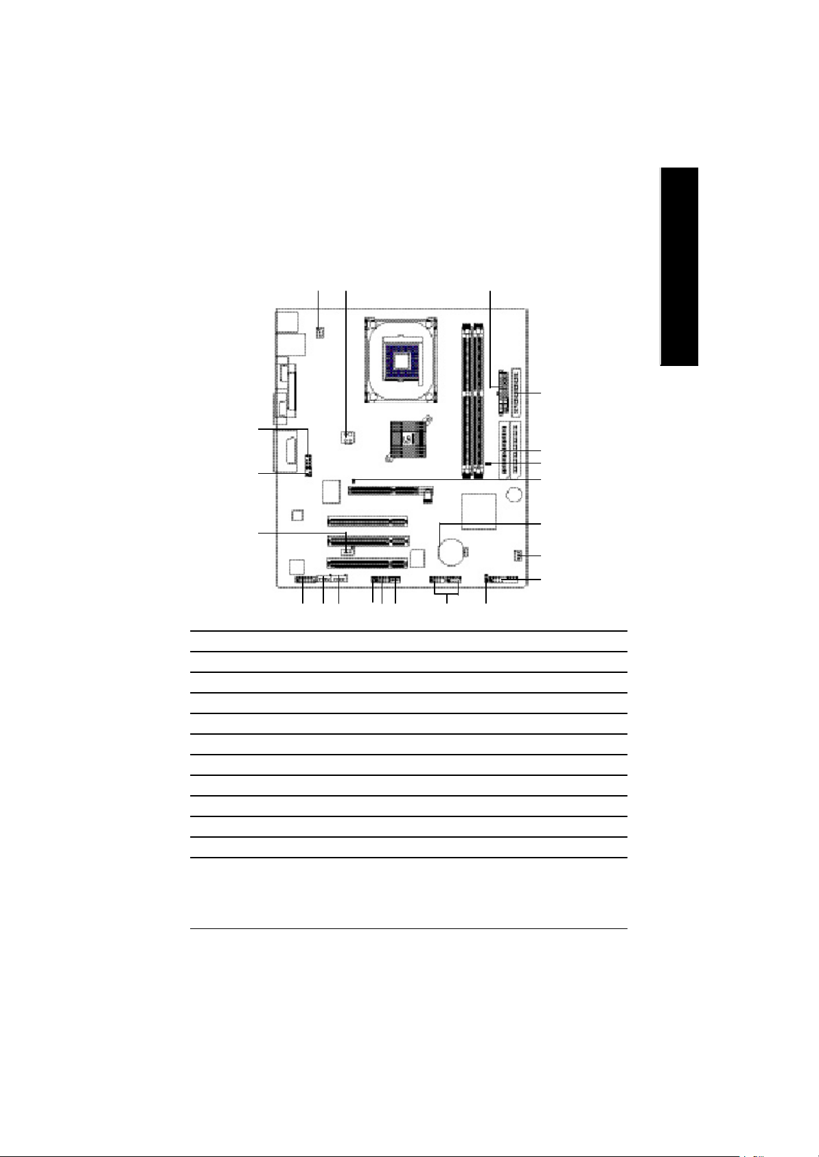
GA-8PEMT4 系列主機板Layout 圖
繁
體
中
文
GA-8PEMT4
(*)只有 GA-8PEMT4 才有此功能
- 7 -
序言
繁
體
第二章 硬體安裝步驟
中
文
請依據下列方式,完成電腦的安裝:
步驟 1 - 安裝中央處理器 (CPU)
步驟 2 - 安裝記憶體模組
步驟 3 - 安裝所有介面卡
步驟 4 - 連接所有訊號線、排線、電源供應線及面板控制線
步驟1
步驟2
步驟4
步驟 2
步驟 4
步驟 4
步驟3
- 8 -GA-8PEMT4 系列主機板
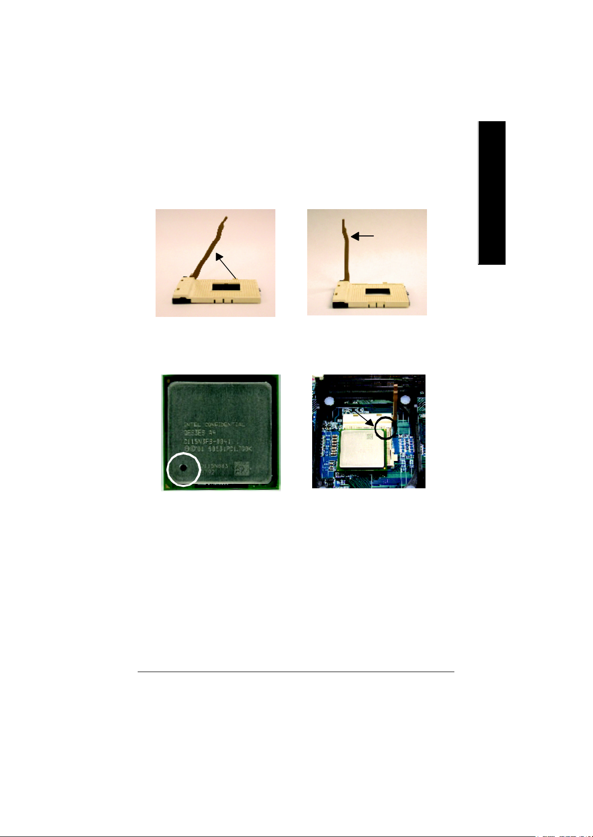
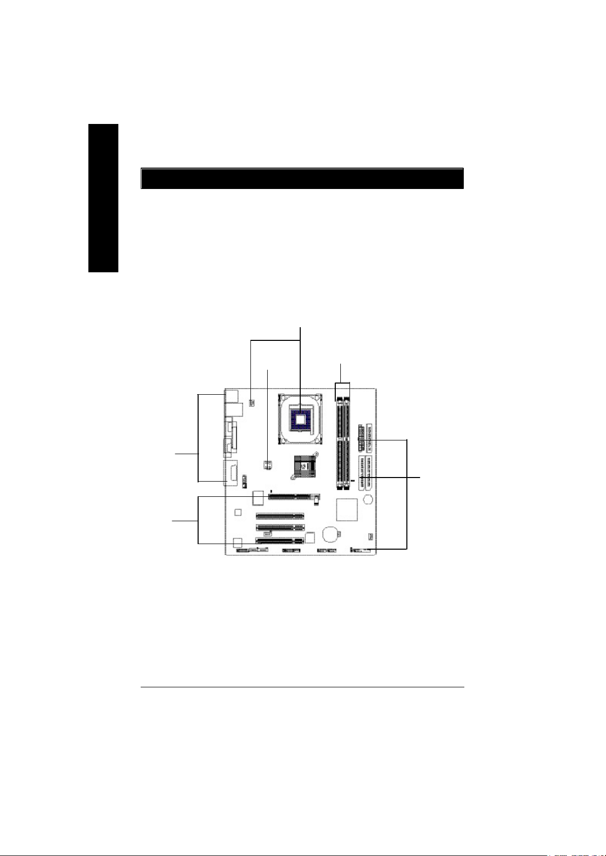
步驟1:安裝中央處理器(CPU)
步驟1-1:中央處理器之安裝
繁
體
中
連桿拉至
約 65 度角
1. 將處理器插座連桿向上拉起至約
65度,連桿有時會有卡住的感覺, 此
時稍加用力繼續將連桿拉至90 度,
並會有”喀”的聲音。
第 1 腳
3. 中央處理器正面
文
連桿
2. 將處理器插座連桿向上拉起
至90 度角的位置。
第 1 腳
4. 將處理器的第一腳( 金色三腳記號
處) 對準插座上的缺腳記號再將處
理器插入插座。處理器插入定位
後,再將連桿向下按至原位。
M 請確認您使用的中央處理器為本主機板的支援範圍。
M 請注意CPU的第一腳位置,若您插入的方向錯誤,處理器就無法插
入,請立刻更改插入方向。
- 9 - 硬體安裝步驟

繁
體
中
文
步驟1-2:中央處理器之散熱裝置安裝
1. 先將CPU 散熱風扇一邊的
卡榫以平均施力的方式往
下壓,直至扣緊為止;以同樣
地方式再將另一邊卡榫扣
緊.
M 使用經 Intel 認證過的散熱風扇。
M CP U 與風扇之間建議黏上散熱膠帶以增強散熱效果。
(當塗抹在 CP U 上的散熱膏呈現硬化的現象時,可能會產生
散熱風扇黏住 CP U 的情況, 在此情況下如果您想移除散熱風
扇將會有損毀 C P U 的可能。為避免此情況發生,我們建議您
可使用散熱膠帶來取代散熱膏, 或是小心地移除散熱風扇。)
M 依您實際所使用的散熱風扇, 以正確方向將風扇確實扣緊。
M 確認 C P U 散熱風扇電源線接至 CPU FAN 接頭,完成安裝。
( 詳細安裝步驟請參考散熱風扇的使用手冊。)
2. 將CPU 散熱風扇的電源線
插入主機板上的”CPU 散
熱風扇電源插座”.
- 10 -GA-8PEMT4 系列主機板
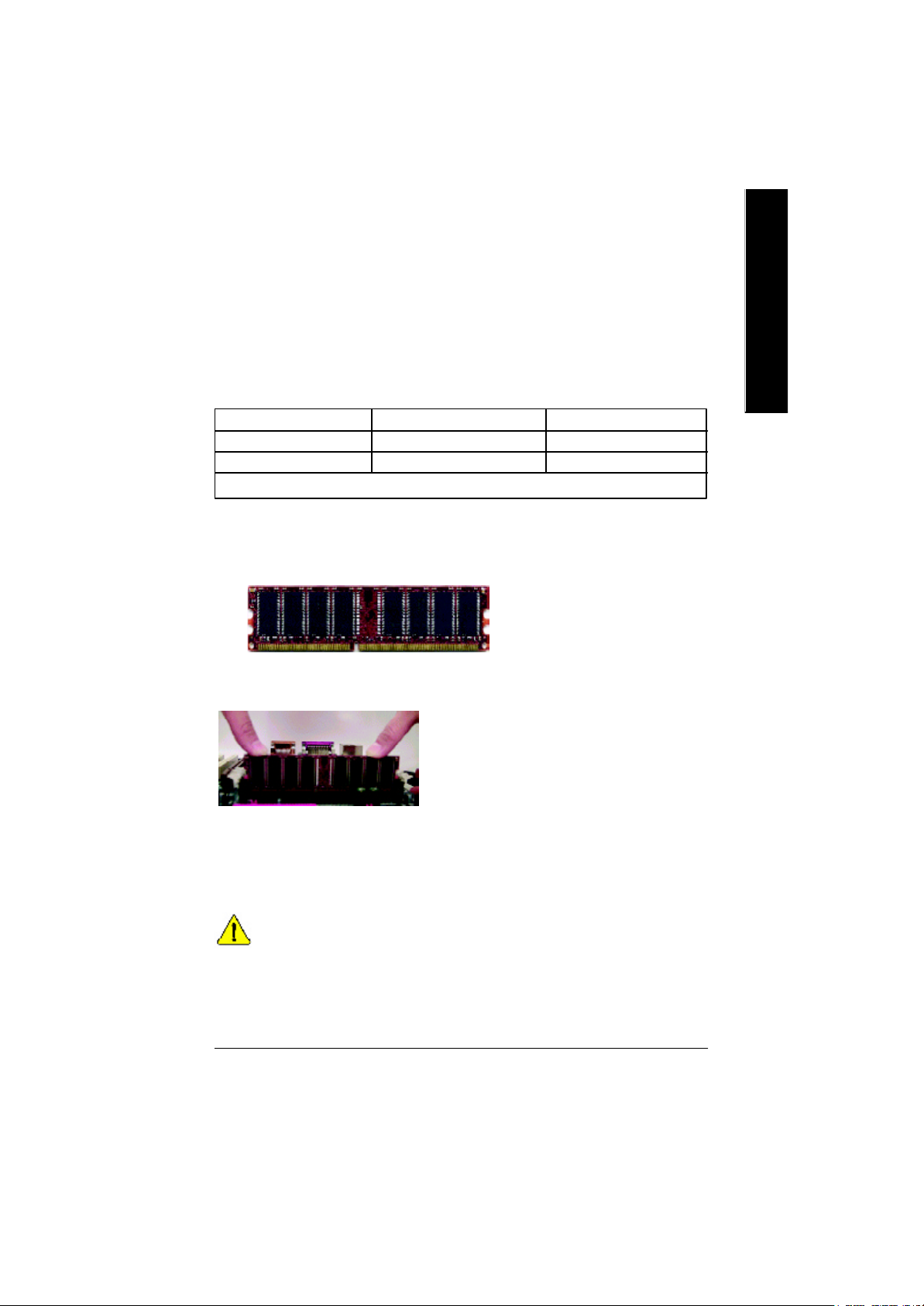
步驟2:安裝記憶體模組
本主機板有2 條184Pin(DIM M )擴充槽,BIOS 會自動偵測記憶體的規格及其大小. 安裝
記憶體只需將DIMM插入其插槽內即可,在不同的插槽,記憶體大小可以不同,建議使
用相同顆粒的記憶體模組,如:NEC, Toshiba, PQI, Winbond.
使用 Unbuffered DDR DIMM 時的總記憶容量:
64 Mbit (2Mx8x4 banks) 64 Mbit (1Mx16x4 banks) 128 Mbit(4Mx8x4 banks)
128 Mbit(2Mx16x4 banks) 256 Mbit(8Mx8x4 banks) 256 Mbit(4Mx16x4 banks)
512 Mbit(16Mx8x4 banks) 512 Mbit(8Mx16x4 banks)
Total System Memory (Max2GB)
備註: Intel 845E/G/PE/GE/GV 晶片組不支援雙顆粒 x16 DDR 記憶體模組.
DDR
繁
體
中
文
1. 記憶體模組有一個凹痕,所以只能以
一個方向插入.
2. 扳開記憶體模組插槽卡榫,以平均施力的方
式,將記憶體模組下壓推入插座.記憶體模組
插入定位後,將卡榫向內按至卡住.
3. 將卡榫向內推,確實卡住記憶體模組
DIMM 。一旦固定位置,兩旁的卡榫便自動
卡住記憶體模組予以固定。試著輕輕搖動記
憶體模組,若不搖晃則裝置成功.
M 記憶體模組設計有防呆標示, 若您插入的方向錯誤, 記憶體模組
就無法插入, 請立刻更改插入方向
- 11 - 硬體安裝步驟
繁
體
中
文
DDR 功能介紹
DDR(Double Data Rate)是PC產業在SDRAM架構上的一項重要演進,利用雙倍的記
憶體頻寬可解決系統資料的瓶頸問題。建立在SDRAM 的基礎架構設計之上,DDR
是一項高效能及低成本兼具的創新技術,能使記憶體廠商、OEM 系統廠商在熟悉
的標準上建構新一代的電腦系統產品。
因為具有優良可行性、價格以及整體市場的支援性,DDR SDRAM將提供優良的
解決方式以及將現有的SDRAM 轉換到DDR SDRAM 的最佳路徑。
DDR 可雙倍讀與寫的資料傳輸速率,利用最高可達2.664GB/s 的傳輸速度,DDR 能
使系統廠商建立一個高效能及低滯留時間的DRAM架構,適合在伺服器、工作站、
高階PC以及進階整合性電腦系統使用。相對於目前SDRAM的3.3 volts 高核心電壓,
DDR 的2.5 volts超低核心電壓將使得DDR 為小型規格的桌上電腦以及筆記型
電腦的最佳技術解決方案。
步驟3:安裝介面卡
1. 在安裝介面卡之前請先詳細閱讀介面卡之使用手冊並將您電腦的電源關掉。
2. 將您電腦外殼拆除,並且讓自己保持接地。(為了使人體不帶電,以防止靜電傷
害電腦設備)。
3. 鬆開螺絲,移開介面卡安裝擴充槽旁的金屬擋片。
4. 將介面卡小心且確實的插入在擴充槽中。
5. 請確定所有介面卡皆確實固定插在該擴充槽,並將螺絲鎖回。
6. 重新將電腦機殼蓋上。
7. 接上電源線,若有必要請至BIOS 程式中設定介面卡之相關設定。
8. 安裝相關驅動程式。
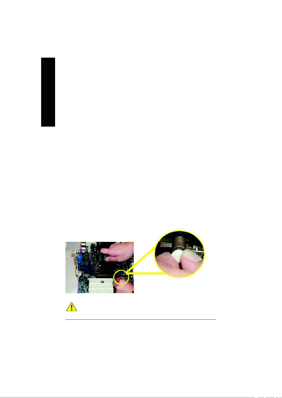
當您要安裝/ 移除 AGP 卡時,請將白
色拉桿向外拉. 再將AGP 卡緩緩插入
AGP 擴充槽中. 放開拉桿 確實卡住
AGP 卡
當您使用 2X(3.3V)的顯示卡, 2X_DET指示燈將會亮起, 那表示您所使用的
顯示卡2X (3.3V)在此主機板上可能造成無法正常開機的情況.
AGP 卡
- 12 -GA-8PEMT4 系列主機板
步驟4:連接所有訊號線、排線、電源供應線及面
板控制線
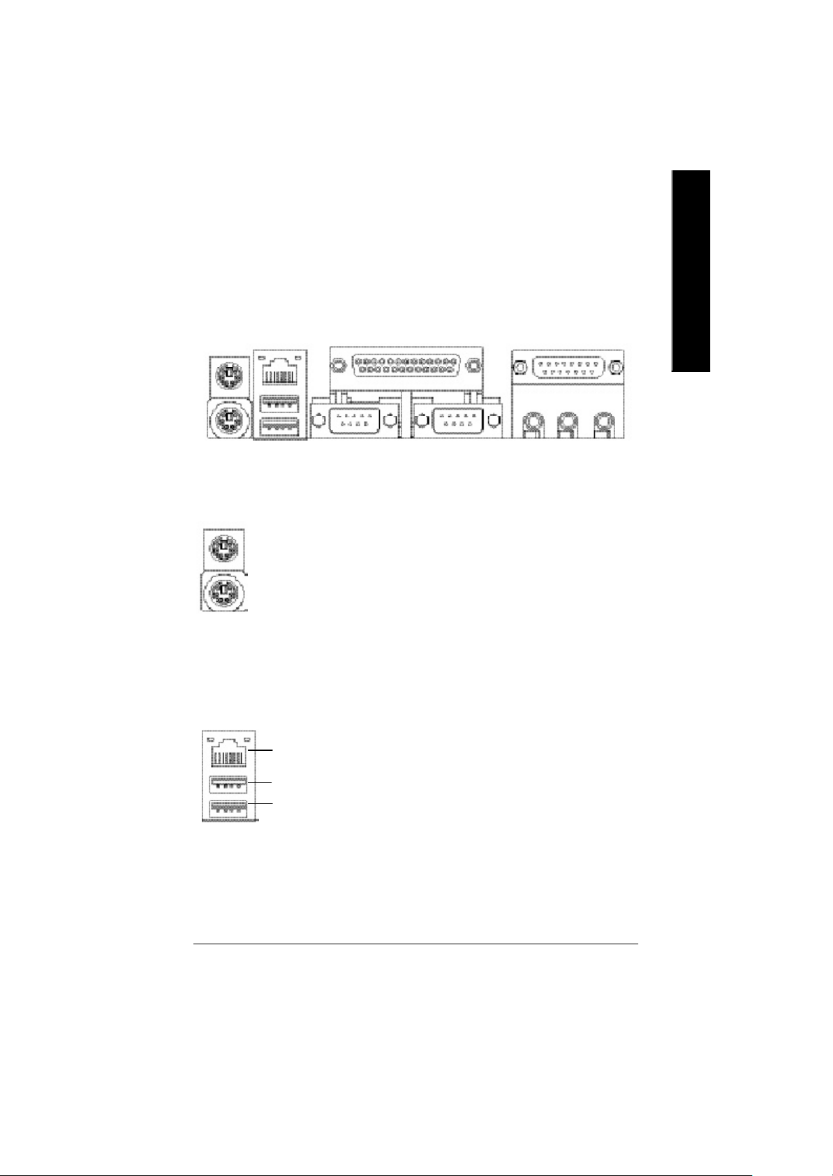
步驟4-1:後方 I/O 裝置插座介紹
u
v(*)
w
x
y
繁
體
中
文
u PS/2 Keyboard / Mouse
(PS/2 鍵盤及 PS / 2 滑鼠插座)
PS/2 Mouse (PS/2 滑鼠插座)
(6 pin Female)
PS/2 Keyboard (PS/2 鍵盤插座)
(6 pin Female)
v USB / LAN(*) Connector
(LAN 通用序列埠, 網路插座)
LAN(*) Connector
(網路插座)
USB0 (通用序列埠 0)
USB1 (通用序列埠1)
Ø 本主機板提供標準PS/2 鍵盤介面及
PS/2 滑鼠介面插座。
Ø當你要使用通用串列埠連接埠時,必須
先確認您要使用的週邊裝置為標準的
USB 介面,如:USB 鍵盤,滑鼠,U SB
掃瞄器,USB ZIP,USB 喇叭等….而且
您也必須確認您的作業系統是否有支援
此功能,或是需要另外再掛其他的驅動
程式,如此才能正常工作,詳情請參考
USB 週邊裝置的使用手冊。
(*)只有GA-8PEMT4 才有此功能
- 13 - 硬體安裝步驟
繁
體
中
文
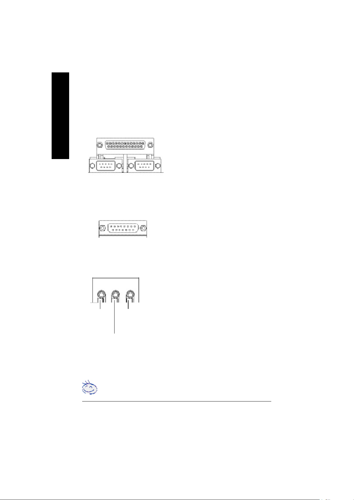
w COMA(串列埠 A)/ COMB
Ø本主機板支援二組標準的串列埠傳輸協
(串列埠 B)/L PT(印表機並列埠插座)
LPT Port
並列埠插座
(25 pin Female)
定之週邊裝置、一組標準的並列傳輸協
定之週邊裝置,您可以依據您的需求連
接您需要的裝置,如並列埠有印表機,
串列埠有滑鼠、數據機等。
COMA
串列埠A
(9 pin Male)
COMB
串列埠B
x GAME/MIDI Ports
(遊戲搖桿控制埠)
GAME/MIDI
遊戲搖桿控制埠
(15 pin Female)
y Audio Connector (音源插座)
Line Out
(前置喇叭)
MIC In
(中置重低音喇叭)
Line In
(後置喇叭)
若您需要更細部的 2-/4-/6-聲道音效設定資料,請參考"二聲/四
聲 / 六聲道音效功能介紹 ".
Ø本主機板支援標準的音效輸入接腳及遊
戲搖桿控制埠,您在設定完成內建音效
的驅動程式後,即可將喇叭輸出接腳接
在音源輸出端。
Ø 麥克風接腳可接在麥克風輸入端,至於
音源輸入端可以接上如:光碟機,隨身
聽及其他音源輸入接腳。
您可以藉由音效軟體去選擇使用
2-/4-/6- 聲道音效功能
假如你要啟動6-channel功能,市請先將音
效軟體設妥,以下有2種硬體接法提供你
選擇.
方法一:
直接將前端喇叭接至”Line Out”音源插
座.再將後端喇叭接至”Line In”音源插
座. 最後將中置重低音喇叭接至”Mic In”
音源插座.
方法二:
你可以參考P19,並聯絡相關代理商購買
SUR_CEN 連接排線套件.
- 14 -GA-8PEMT4 系列主機板
步驟4-2:插座及跳線介紹
繁
體
1 3 4
10
11
14
1312
18
1516
17
19
7
1) CPU_FAN 12) CD_IN
2) SYS_FAN 13) AUX_I N
3) ATX_12V 14) SPDI F_O
4) ATX 15) F_USB1/ F_US B2
5) IDE1/IDE2 16) IR_CI R
6) FDD 17) WOL
7) PWR_LED 18) MODEM(*)
8) 2X_DET 19) CI
9) F_PANEL 20) CLR_PWD
10) F_AUDI O 21) BAT
11) S UR_CEN
中
文
6
5
20
8
21
2
9
(*)只有 GA-8PEMT4 才有此功能
- 15 - 硬體安裝步驟
繁
體
中
文
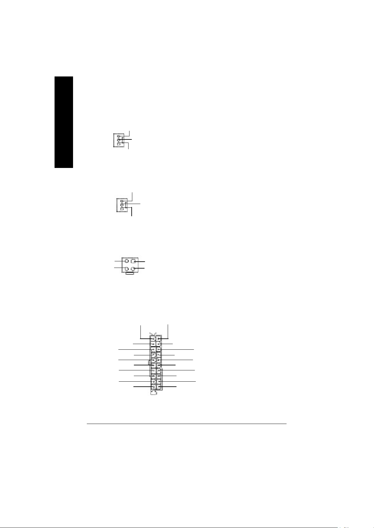
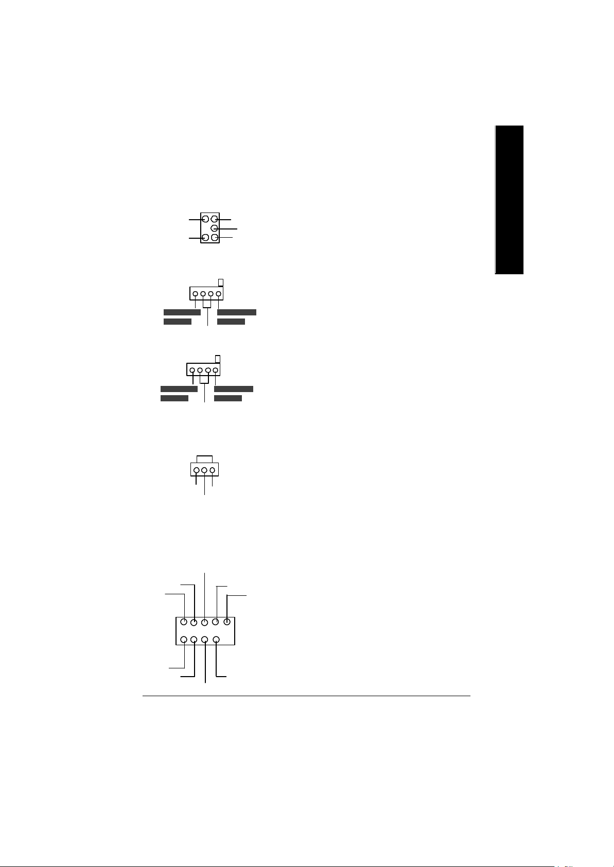
1)CPU_FAN
(CPU 散熱風扇電源插座)
Sense
1
+12V
接地線
Ø 請特別注意,當我們安裝處理器時要
特別注意將散熱風扇安裝妥當,不然
您的處理器將處於不正常的工作環
境,甚至會因為溫度過高,而燒毀處
理器。此CPU 散熱風扇電源插座,提
供最大電流為600 毫安培。
2)SYS _FAN
(系統 散熱風扇電源插座)
Sense
1
+12V
接地線
3)ATX_12V( +12V P 電源插座)
1
2
接地線
+12V
4
接地線
+12V
3
4)ATX (ATX 電源插座)
接地線
PS-ON(Soft On/Off)
接地線
接地線
-12V
接地線
-5V
VCC
VCC
3.3V
1
20
3.3V
3.3V
Ø 請特別注意,一般我們建議ATX的主機
板,至少安裝一台電源散熱風扇,因
為可以增加機殼內部散熱的速度進而
減低機殼內的工作溫度
Ø 請特別注意,此ATX +12V 電源插座為
提供CPU 電源使用。
Ø 請特別注意,先將AC 交流電(110/
220V)拔除,再將ATX電源插頭緊密的
插入主機板的ATX 電源插座,並接好
其相關配備才可以將AC 交流電(110/
220V)插入交流電源插座。
接地線
VCC
接地線
VCC
接地線
Power Good
5V SB (Stand by +5V)
+12V
- 16 -GA-8PEMT4 系列主機板
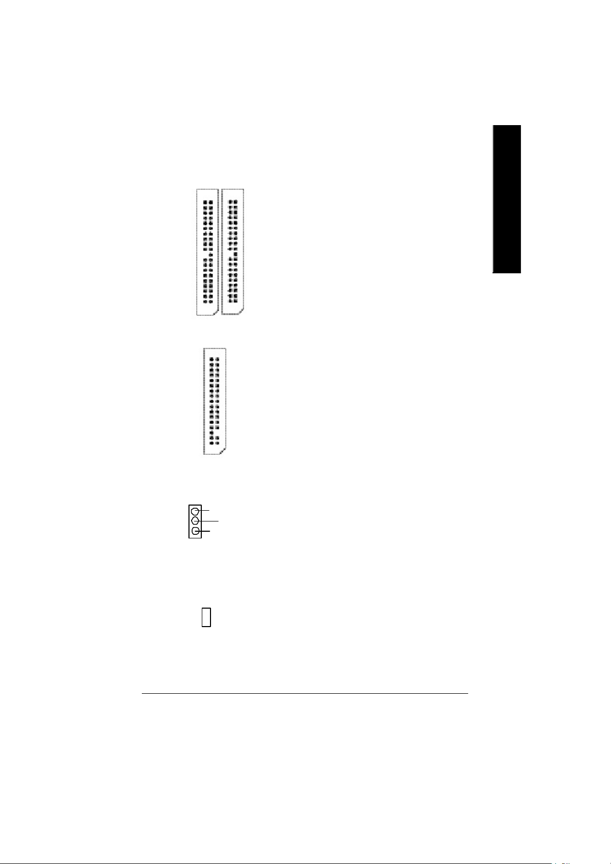
5)IDE1/ IDE2 (第一組及第二組 I D E 插座)
Ø 請特別注意:
請將您的第一顆硬碟連接第一組 IDE
插座.光碟機接至第二組 IDE 插座.
通常排線的第1Pin 會以紅色表示,請
連接至插座的Pin1 位置.
繁
體
中
文
第一組IDE 插座
IDE1
IDE2
6)FDD (軟碟機插座)
軟碟機插座
7)PWR_LED
MPD-
MPD-
MPD+
1
第二組IDE 插座
1
Ø 請特別注意:
通常排線的第1Pin 會以紅色表示,請
連接至插座的Pin1 位置.
1
Ø 此PWR_LED 是連接系統電源指示燈
指示系統處於ON 或OFF.當Power LED
在Suspend 模式下,會以閃爍的方式
呈現。
8)2X_DET
Ø 當您使用 2X(3.3V)的顯示卡, 2X_DET
指示燈將會亮起, 那表示您所使用的
+ -
顯示卡 2X (3.3V)在此主機板上可能造成
無法正常開機的情況.
- 17 - 硬體安裝步驟
繁
體
中
文
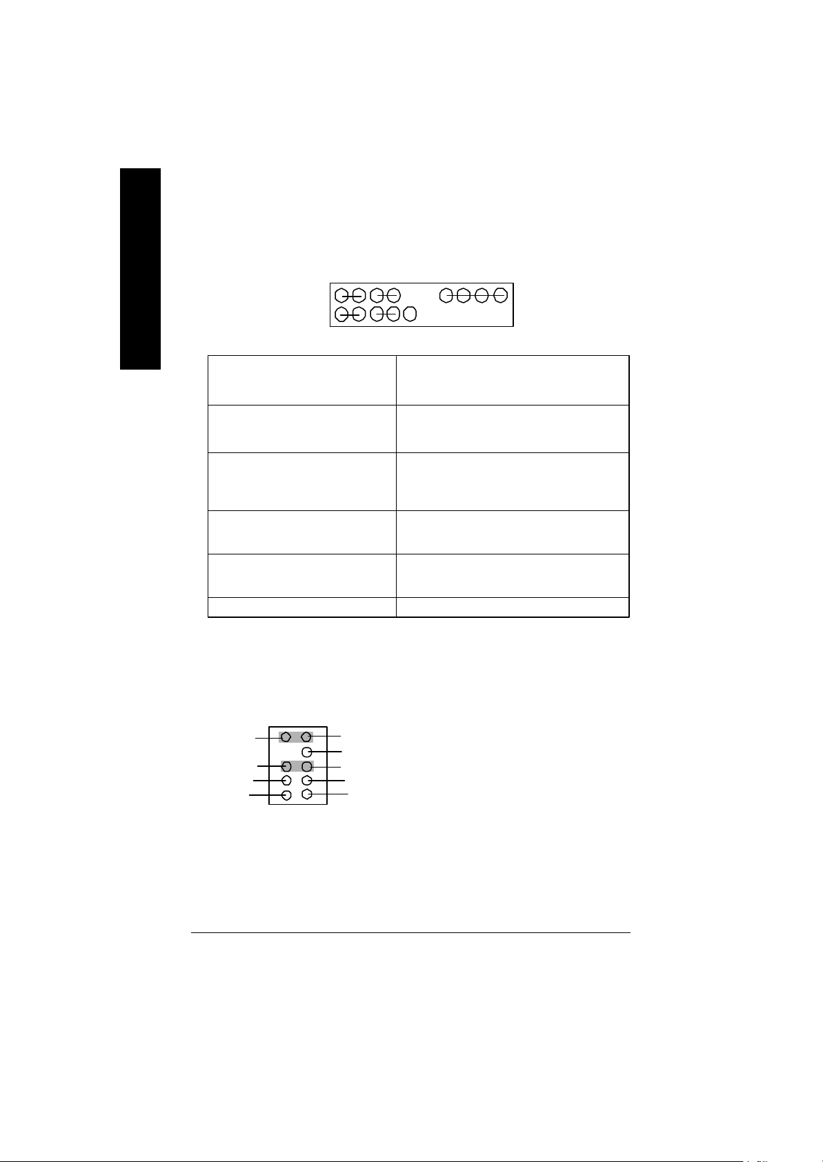
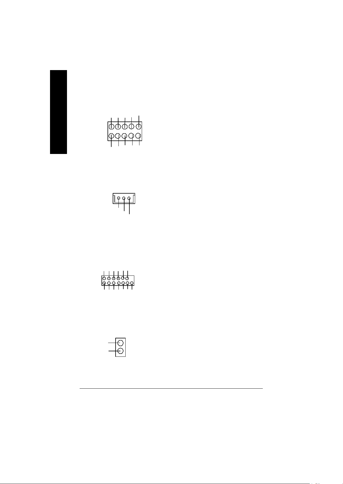
9)F_PANEL (2x10 Pins 前端控制面板插座)
MPD+
1
2
1 19
1
HD+
HD (IDE Hard Disk Active LED) Pin 1: LED anode(+)硬碟指示燈正極
硬碟動作指示燈(藍色) Pin 2: LED cathode(-)硬碟指示燈負極
SPK (Speaker Connector)喇叭接腳 Pin 1: VCC(+) +5v 電源接腳
(橘色) Pin 2- Pin 3: NC 空腳
RES (Reset Switch)系統重置開關 Open: Normal Operation 一般運作
(綠色) Close: Reset Hardware System
PW (Soft Power Connector) Open: Normal Operation 開路:一般運作
按鍵開關機(紅色) Close: Power On/Off 短路:開機/ 關機
MPD(Message LED/Power/ Pin 1: LED anode(+)省電指示燈正極
Sleep LED)(黃色) Pin 2: LED cathode(-)省電指示燈負極
NC(紫色) 無作用
MPD-
HD-
PW-
PW+
1
1
RES-
RES+
M 請注意正負極性
Pin 4: Data(-) 訊號接腳
強迫系統重置開機
M 無正負極性正反皆可使用
M 無正負極性正反皆可使用
M 請注意正負極性
NC
SPK+
1
SPK-
20
Ø 請特別注意,當您購買電腦機殼時,電腦機殼的控制面板有電源指示燈,喇
叭,系統重置開關,電源開關等,你可以依據上列表格的定義加上連接。
10)F_AUDIO (第二組音源插座)
910
Rear Audio (L)
Rear Audio (R)
接地線
2
Front Audio (L)
Reserved
Front Audio (R)
REFPOWER
MIC
1
Ø 請特別注意,前端USB 接腳是有方
向性的,所以安裝USB 裝置時,要
特別注意極性,而且前端USB 連接
排線為選擇性的功能套件,可以聯
絡相關代理商購買。
- 18 -GA-8PEMT4 系列主機板
11)SUR_CEN
(中置聲道與重低音模組擴充插座)
BASS_OUT
SUR OUTR
CENTER_OUT
接地線
SUR OUTL
1
Ø 你可以參考左側接腳定義,並聯絡相
關代理商購買SUR_C EN 連接排線套
件.
繁
體
中
文
12)CD_IN (光碟機音源插座)
1
接地腳
13)AUX_IN ( 外接音源輔助插座)
1
接地腳
14)SPDIF_O (SPDIF Out)
1
接地線
VCC
SPDIF Out
Ø 光碟機音源插座:將CD-ROM 或
DVD-ROM 的CD 音源連接至此主機板
內建音效卡中。
Ø 外接音源輔助插座:將電視協調器或
MPEG 解壓縮卡的音源連接至主機板
內建音效卡中。
Ø Sony/Philip Digital Interface Format為新力/
飛利浦所制定的數位介面格式,
SPDIF 輸出能夠提供數位音效給內含
AC- 3 解碼器的外接喇叭或AC -3 解碼
器。請特別注意,使用此功能時,須
確認您的音響系統具有數位輸入
(SPDIF In)功能。
15)F_USB1/F_USB2(前端通用串列埠插座)
Ø 請特別注意,前端USB接腳是有方向
性的,所以安裝USB裝置時,要特別
注意極性,而且前端USB連接排線為
選擇性的功能套件,可以聯絡相關代
理商購買。
USB Dy-
Power
USB Dy+
接地腳
USB Over Current
1
Power
USB Dx-
USB Dx+
接地腳
- 19 - 硬體安裝步驟
繁
體
中
文
16)IR_CIR
Ø 請特別注意,當你使用紅外線接腳
NC
VCC
接地腳
CIRRX
NC
1
VCC
NC
IRRX
IRTX
接地腳
時,需要特別注意紅外線接腳是有
方向性的,且紅外線搖控裝置配件
為選購之套件,需另外購買,此主
機板支援標準IR 傳輸協定。若您是
單純使用IR 功能,請將紅外線搖控
裝置配件連接Pin1 到 Pin 5。
17)W OL(網路卡喚醒功能插座)
1
+5V SB
接地腳
Signal
18)Modem(*)
VCC
+12V
VAUX33
AC OUT
AC DIN
AC BCK
NC
NC
AC RSTB
AC DOUT
AC SYNC
VDD33
1
接地腳
19) CI(電腦機殼被開啟偵測)
Signal
接地腳
1
Ø 主要是透過區域網路傳輸。若要使用
LAN 喚醒功能,您的網卡上的晶片組
必須支援此功能,並使用排線連接
LAN 卡和主機板上的WOL 接腳。
Ø 你可以參考左側接腳定義,並聯絡相
關代理商購買MODEM 連接排線套
件.
Ø 本主機板提供電腦機殼被開啟偵測
功能,當您要使用此功能需搭配外
接式偵測裝置.
(*)只有 GA-8PEMT4 才有此功能
- 20 -GA-8PEMT4 系列主機板
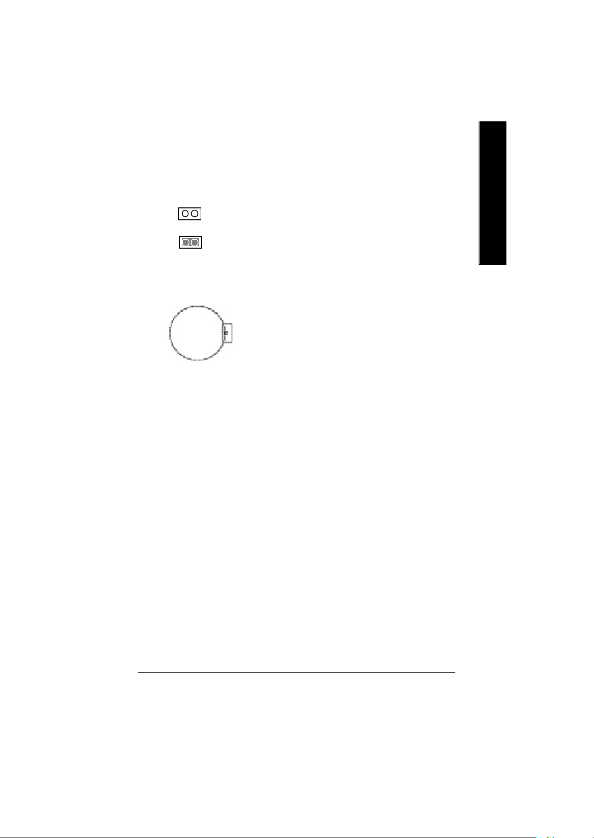
20) CLR_PWD
1
1
open: 清除密碼
close: 一般運作
Ø 當Jumper 設為open 時,會將BIOS 內的
密碼設定清除(包括User passw ord及
Supervisor password).當Jumper 設為close
時,則維持原本的狀態.
M 此功能可提供您清除BIOS內的密碼設
定.
繁
體
中
文
21)BAT(電池)
警告
v 如果電池有任何不正確的移除動
作,將會產生危險。
+
v 如果需要更換電池時請更換相同廠
牌、型號的電池。
v 有關電池規格及注意事項請參考電
池廠商之介紹。
- 21 - 硬體安裝步驟

繁
體
中
文
- 22 -GA-8PEMT4 系列主機板
繁
第三章 BIOS 組態設定
基本上主機板所附Award BIOS 便包含了C M OS SETUP 程式,以供使用者自行依照
需求,設定不同的數據,使電腦正常工作,或執行特定的功能。
CMOS SETUP會將各項數據儲存於主機板上內建的 CMOS SRAM中,當電源關閉時,
則由主機板上的鋰電池繼續供應CM OS SRAM 所需電力。
當電源開啟之後,BIOS 開始進行POS T(Power On Self Test開機自我測試)時,按
下<Del >鍵便可進入Aw ard BIO S 的CM OS S ETU P主畫面中。如果您需要進階的
BIOS 設定,當您在BIOS 設定畫面時按下“Ctrl+F1”即可進入。
操作按鍵說明
h 移到上一個項目
i 移到下一個項目
f 移到左邊的項目
g 移到右邊的項目
Esc 回到主畫面,或從主畫面中結束SETU P程式
Page Up 改變設定狀態,或增加欄位中之數值內容
Page Down 改變設定狀態,或減少欄位中之數值內容
F1 可顯示目前設定項目的相關說明
F2 功能保留
F3 功能保留
F4 功能保留
F5 可載入該畫面原先所有項目設定(但不適用主畫面)
F6 可載入該畫面之Fail-Safe 預設設定(但不適用主畫面)
F7 可載入該畫面之Optimized 預設設定(但不適用主畫面)
F8 Q-Flash 功能
F9 功能保留
F10 儲存設定並離開CM OS SETUP 程式
體
中
文
BIOS 組態設定- 23 -
繁
體
中
文
如何使用輔助說明
主畫面的輔助說明
當您在SETUP 主畫面時,隨著選項的移動,底下便跟著顯示︰目前被選到的
SETUP 項目的主要設定內容。
設定畫面的輔助說明
當您在設定各個欄位的內容時,只要按下<F1 >,便可得到該欄位的設定預設值
及所有可以的設定值,如BIOS 預設值或 CMOS SETUP 預設值,若欲跳離輔助說明
視窗,只須按<Esc>鍵即可。
主畫面功能(BIOS 範例版本:F1)
當您進入CMOS SETUP 設定畫面時,便可看到如下之主畫面,從主畫面中可以讓你
選擇各種不同之設定選單,你可以用上下左右鍵來選擇你要設定之選項並按Enter
進入子選單。
CMOS Setup Utility-Copyright (C) 1984-2002 Award Software
}Standard CMOS Features Top Performance
}Advanced BIOS Features Load Fail-Safe Defaults
}Integrated Peripherals Load Optimized Defaults
}Power Management Setup Set Supervisor Password
}PnP/PCI Configurations Set User Password
}PC Health Status Save & Exit Setup
}Frequency/Voltage Control Exit Without Saving
ESC:Quit higf:Select Item
F8: Q-Flash F10:Save & Exit Setup
Time, Date, Hard Disk Type...
圖 1: 主畫面功能
若在主畫面功能選項中,沒有找到您所需要的選項設定,請按
“Ctrl+F1”進入進階BIOS 畫面設定,作進一步搜尋。
l Stand ard CMOS Features (標準 CMOS 設定)
設定日期、時間、軟硬碟規格、及顯示器種類。
l Ad vanced BIOS Features (進階 BIOS 功能設定)
設定BIOS提供的特殊功能,例如病毒警告、開機磁碟優先順序、磁碟代號交
換....等。
- 24 -GA-8PEMT4 系列主機板

l Integrated Peri pherals (整合週邊設定)
在此設定畫面包括所有週邊設備的的設定。如COM Port 使用的IRQ 位址,LPT
Port 使用的模式SPP 、 EPP 或EC P 以及IDE 介面使用何種DMA Mode…..等。
l Power Manag ement Setup (省電功能設定)
設定CPU 、硬碟、GREEN 螢幕等裝置的省電功能運作方式。
l PnP/PCI Confi guration (隨插即用與 PCI 組態設定)
設定ISA 之 PnP 即插即用介面以及PC I 介面的相關參數。
l PC H ealth Status (電腦健康狀態)
系統自動偵測電壓,溫度及風扇轉速等。
我們不建議您任意改變此項預設值,除非您真的需要去更改設定。
l Frequency/Voltage Control (頻率 / 電壓控制)
設定控制CPU 時脈及倍頻調整。
l Top Performance (最高效能)
如果您想使您的系統獲得最高效能,請將"Top Performance" 設定為 "Enabled" 。
l Load Fail-Safe Defaults (載入 Fail-Safe 預設值)
執行此功能可載入BIOS的CMOS設定預設值,此設定是比較保守,但較能進
入開機狀態的設定值。
l Load Op timized Defaults (載入 Optimized預設值)
執行此功能可載入Optimized的CMOS設定預設值,此設定是較能發揮主機板速
度的設定。
l Set Supervi sor Password (管理者的密碼)
設定一個密碼,並適用於進入系統或進入SETU P修改CMOS 設定。
l Set U ser Password (使用者密碼)
設定一個密碼,並適用於開機使用PC 及進入BIOS 修改設定 。
l Save & Exit Setup (儲存並結束)
儲存所有設定結果並離開SETUP程式,此時BIOS會重新開機,以便使用新的
設定值,按<F10 >亦可執行本選項。
l Exi t Without S aving (結束 SETUP程式)
不儲存修改結果,保持舊有設定重新開機,按<ESC>亦可直接執行本選項。
繁
體
中
文
BIOS 組態設定- 25 -
 Loading...