

Gigabyte GA-8IP775 User Manual

GA-8IP775 Series
Intel® Pentium® 4 LGA775 Processor Motherboard
User's Manual
Rev. 1003
12ME-8IP775-1003

Sep. 10, 2004
GA-8IP775/GA-8IP775-G
Motherboard
Sep. 10, 2004
GA-8IP775/GA-8IP775-G
Motherboard

Copyright
© 2004 GIGA-BYTE TECHNOLOGY CO., LTD. All rights reserved.
The trademarks mentioned in the manual are legally registered to their respective companies.
Notice
The written content provided with this product is the property of Gigabyte.
No part of this manual may be reproduced, copied, translated, or transmitted in any form or by any
means without Gigabyte's prior written permission. Specifications and features are subject to
change without prior notice.
Product Manual Classification
In order to assist in the use of this product, Gigabyte has categorized the user manual in the
following:
For quick installation, please refer to the "Hardware Installation Guide" included with the
product.
For detailed product information and specifications, please carefully read the
"Product User Manual".
For detailed information related to Gigabyte's unique features, please go to Gigabyte's
website under "Technology Guide" where information can be downloaded in .pdf format.
For more product details, please click onto Gigabyte's website at www.gigabyte.com.tw

Table of Contents
GA-8IP775(-G) Motherboard Layout ............................................................................. 6
Block Diagram ............................................................................................................... 7
Chapter 1 Hardware Installation.................................................................................... 9
1-1 Considerations Prior to Installation ................................................................. 9
1-2 Feature Summary .......................................................................................... 10
1-3 Installation of the CPU and Heatsink ............................................................ 12
1-3-1 Installation of the CPU .......................................................................................... 12
1-3-2 Installation of the Heatsink ................................................................................... 13
1-4 Installation of Memory ................................................................................... 14
1-5 Installation of Expansion Cards .................................................................... 16
1-6 I/O Back Panel Introduction .......................................................................... 17
1-7 Connectors Introduction ................................................................................ 18
Chapter 2 BIOS Setup ............................................................................................... 29
The Main Menu (For example: BIOS Ver. : E2) ....................................................... 30
2-1 Standard CMOS Features ............................................................................. 32
2-2 Advanced BIOS Features ............................................................................. 34
2-3 Integrated Peripherals ................................................................................... 36
2-4 Power Management Setup ............................................................................ 40
2-5 PnP/PCI Configurations ................................................................................ 42
2-6 PC Health Status ........................................................................................... 43
2-7 Frequency/Voltage Control ........................................................................... 45
2-8 Load Fail-Safe Defaults ................................................................................ 47
2-9 Load Optimized Defaults ............................................................................... 47
2-10 Set Supervisor/User Password ..................................................................... 48
2-11 Save & Exit Setup ......................................................................................... 49
2-12 Exit Without Saving ....................................................................................... 49
- 4 -

Chapter 3 Install Drivers ............................................................................................ 51
3-1 Install Chipset Drivers ................................................................................... 51
3-2 Software Applications .................................................................................... 52
3-3 Driver CD Information ................................................................................... 52
3-4 Hardware Information .................................................................................... 53
3-5 Contact Us ..................................................................................................... 53
Chapter 4 Appendix ................................................................................................... 55
4-1 Unique Software Utilities ............................................................................... 55
4-1-1 Xpress Recovery Introduction .............................................................................. 55
4-1-2 Flash BIOS Method Introduction .......................................................................... 58
4-1-3 2 / 4 / 6 / 8 Channel Audio Function Introduction ................................................ 67
4-1-4 Jack-Sensing and UAJ Introduction ..................................................................... 73
4-2 Troubleshooting............................................................................................. 75
- 5 -
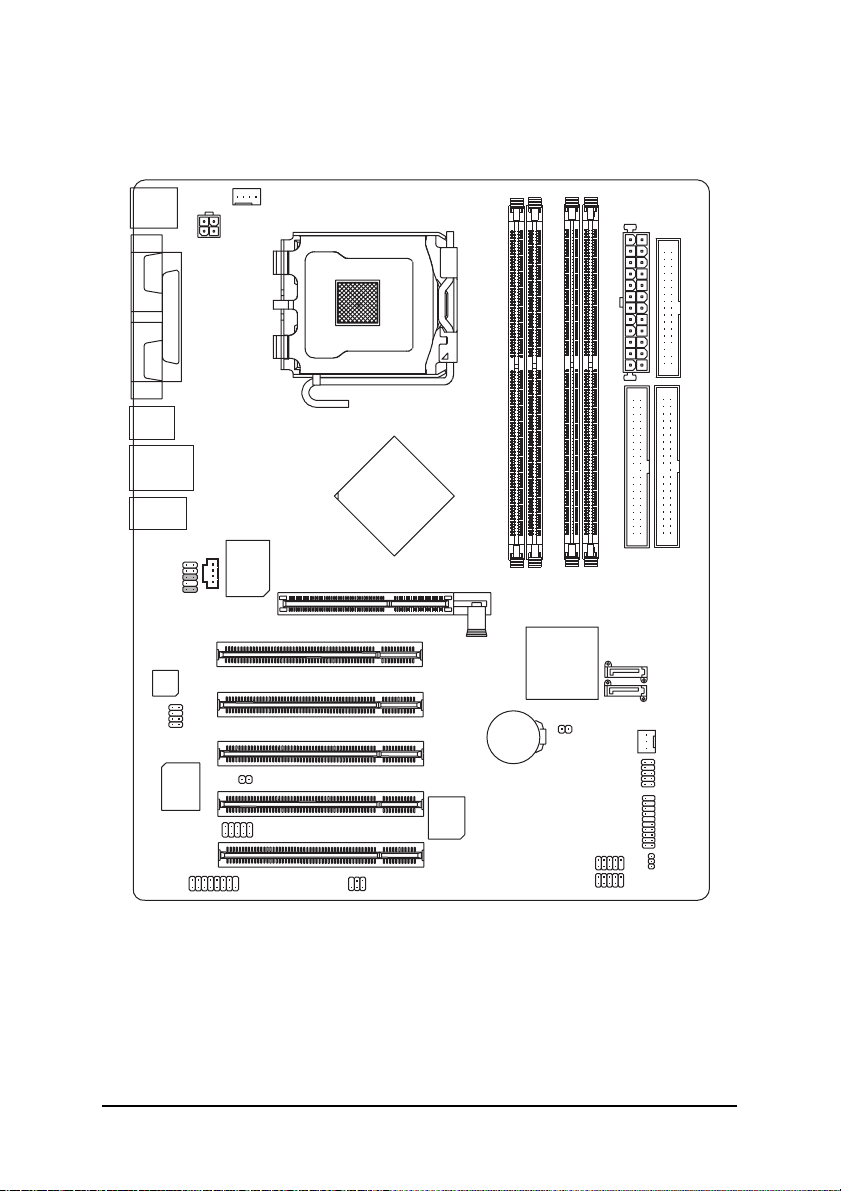
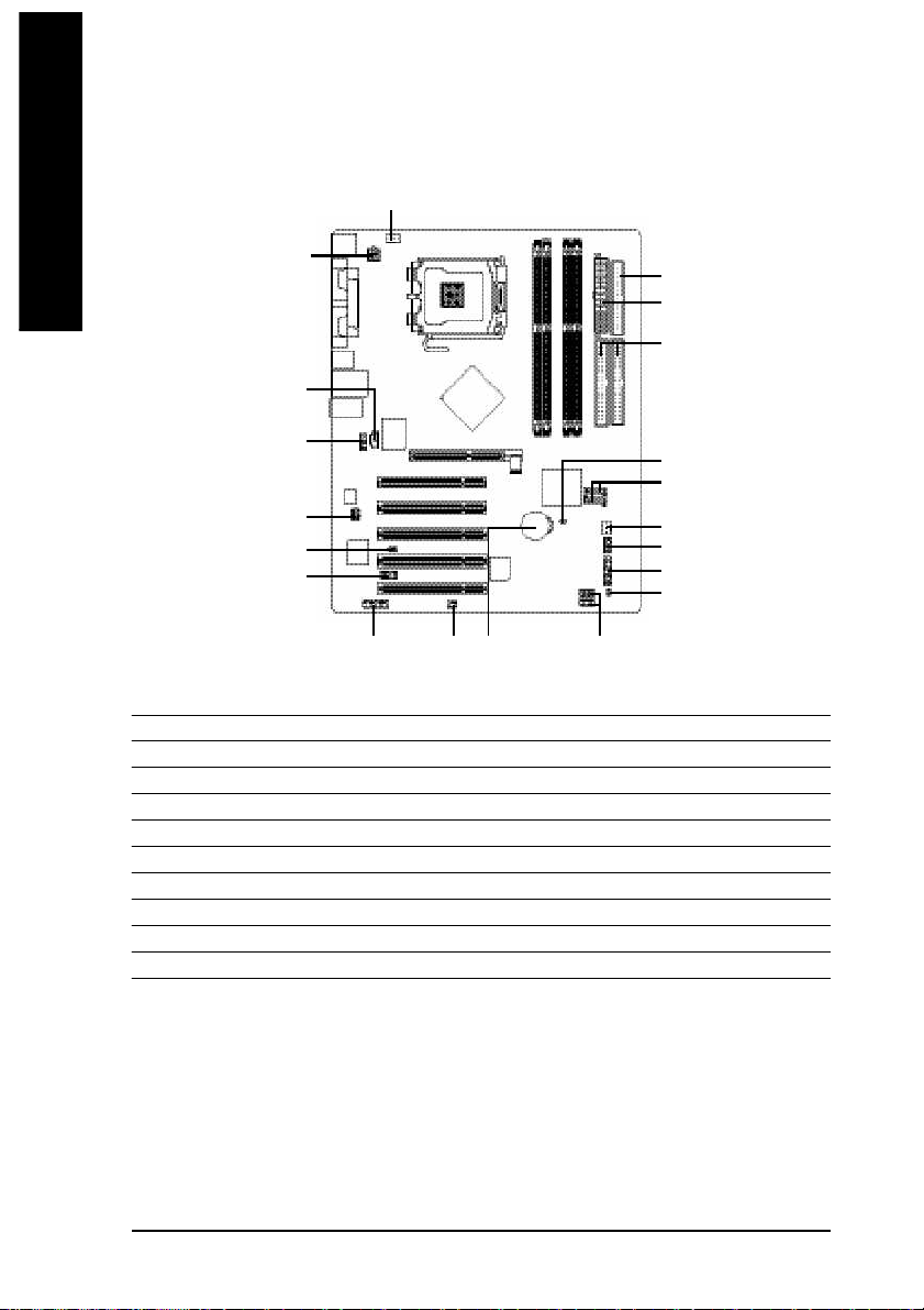
GA-8IP775(-G) Motherboard Layout
KB_MS
COMA
COMB
R_USB
USB
AUDIO
F_AUDIO
CODEC
SUR_CEN
ATX_12V
LPT
)
*
(
LAN
CD_IN
Marvell
8001 (*
DUAL CHANNEL DDR
SATA
IT8712
GAME
CPU_FAN
)
CI
IR_CIR
Intel® 865P
P4 Titan
SPDIF_IO
LGA775
PCI4
PCI5
PCI1
PCI2
PCI3
AGP
BIOS
GA-8IP775(-G)
DDR1
DDR2
DDR3
ICH5
BAT
CLR_CMOS
INFO_LINK
DDR4
F_USB2
ATX
IDE2
F_USB1
FDD
IDE1
SATA1
SATA0
SYS_FAN
F_PANEL
PWR_LED
(*) Only for GA-8IP775-G.
- 6 -
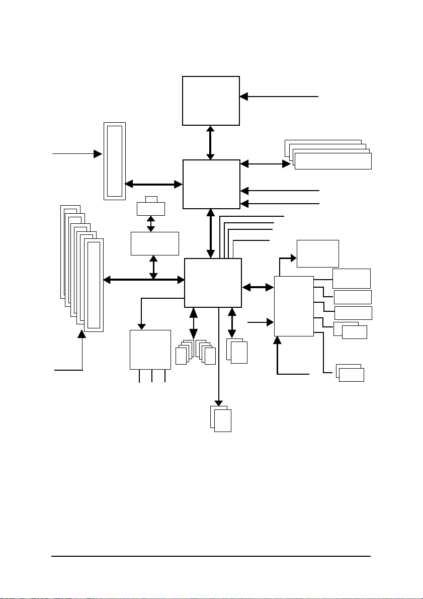
Block Diagram
AGPCLK
(66MHz)
5 PCI
PCICLK
(33MHz)
AGP 8X/4X
)
RJ45 (*
Marvell 8001(*
AC97 Link
AC97
CODEC
MIC
LINE-IN
LINE-OUT
)
8 USB
(2.0/1.1)
LGA775
Processor
Intel 865P
Ports
System Bus
800/533MHz
ICH5
CPUCLK+/- (200/133MHz)
266/333/400MHz
48 MHz
LPC BUS
24 MHz
ATA33/66/100
IDE Channels
Serial ATA
Channels
ZCLK (66MHz)
HCLK+/- (200/133MHz)
66MHz
33 MHz
14.318 MHz
BIOS
IT8712
33 MHz
DDR
Game Port
Floppy
LPT Port
PS/2
KB/Mouse
COM
Ports
(*) Only for GA-8IP775-G.
- 7 -

- 8 -

English
Chapter 1 Hardware Installation
1-1 Considerations Prior to Installation
Preparing Your Computer
The motherboard contains numerous delicate electronic circuits and components which can
become damaged as a result of electrostatic discharge (ESD). Thus, prior to installation, please
follow the instructions below:
1. Please turn off the computer and unplug its power cord.
2. When handling the motherboard, avoid touching any metal leads or connectors.
3. It is best to wear an electrostatic discharge (ESD) cuff when handling electronic components
(CPU, RAM).
4. Prior to installing the electronic components, please have these items on top of an antistatic pad or
within a electrostatic shielding container.
5. Please verify that you the power supply is switched off before unplugging the power supply connector
from the motherboard.
Installation Notices
1. Prior to installation, please do not remove the stickers on the motherboard. These stickers are required
for warranty validation.
2. Prior to the installation of the motherboard or any hardware, please first carefully read the information
in the provided manual.
3. Before using the product, please verify that all cables and power connectors are connected.
4. To prevent damage to the motherboard, please d o not allow screws to come in contact with the
motherboard circuit or its components.
5. Please make sure there are no leftover screws or metal components placed on the motherboard or
within the computer casing.
6. Please do not place the computer system on an uneven surface.
7. Turning on the computer power during the installation process can lead to damage to system
components as well as physical harm to the user.
8. If you are uncertain about any installation steps or have a problem related to the use of the product,
please consult a certifi ed computer technician.
Instances of Non-Warranty
1. Damage due to natural disaster, accident or human cause.
2. Damage as a result of violating the conditions recommended in the user manual.
3. Damage due to improper installation.
4. Damage due to use of uncertified components.
5. Damage due to use exceeding the permitted parameters.
6. Product determined to be an unofficial Gigabyte product.
Hardware Installation- 9 -

English
1-2 Feature Summary
Motherboard w GA-8IP775 Series Motherboard:
GA-8IP775-G/GA-8IP775
CPU w Supports the latest Intel® Pentium® 4 LGA775 CPU
w Supports 800/533MHz FSB
w L2 c ache varies with CPU
Chipset w Northbridge: Intel® 865P
w Southbridge: Intel® IC H5
Memory w 4 DDR DIMM memory slots (supports up to 4GB memory)
w Supports dual channel DDR 400
(Note 2)
/333/266 DIMM
w Supports 2.5V DDR DIMM
Slots w 1 AGP s lot
w 5 PCI slots
IDE Connections w 2 IDE connection (UDM A 33/ATA 66/ATA 100), allows connection of 4
IDE de vices
FDD Connections w 1 FDD c onnection, allows connection of 2 FDD devices
Onboard SATA w 2 Seri al ATA connections
Peripherals w 1 parallel port supporting Norm al/EPP/ECP mode
w 2 Serial port (COM A/COMB)
w 8 USB 2.0/1.1 ports (rear x 4, front x 4 via cable)
w 1 front audio connector
w 1 IR/CIR connector
w 1 PS/2 key board port
w 1 PS/2 mo use port
Onboard LAN(*
)
w Onboard M arvell 8001 chip (10/100/1000 M bit)
w 1 R J 45 port
Onboard Audio w ALC850 CODEC (UAJ)
w Supports Jack Sensing function
w Supports 2 / 4 / 6 / 8 channel audio
w Supports Line In / Line Out / MIC connection
w Surround Back Speaker (use of Surround-Kit to select)
w SPDIF In / Out
w CD In / Game connector
(Note 1)
Due to chipset (Intel 865P) architecture limitation, a FSB 80 0 Pentium 4 processor will support
DDR400 memory m odule. A FSB 533 Pentium 4 processor will support DDR333 and DDR266
memory module.
(Note 1) Due to standard PC ar chitecture, a certain amount of mem ory is reserved for system usage and
therefore the actual mem ory size is less than the stated amount.
For exam ple, 4 GB of memory size will instead be shown as 3.xxGB memory during system startup.
(Note 2) When FSB800 is selected as CPU frequency, m emory will automatically adjust to DDR400.
(*) Only for GA-8IP775-G.
GA-8IP775 Series Motherboard - 10 -

English
I/O Control w IT8712
Hardware M onitor w System voltage detec tion
w CPU temperature detection
w CPU / System fan speed detection
w CPU warning temperature
w CPU / Systemfan failure warning
w CPU smart fan control
BIOS w Use of licensed AWARD BIOS
w Supports Q-Flash
Additional Features w Supports @BIOS
w Supports EasyTune
Overclocking w Over Voltage via BIOS (CPU/DDR/AGP)
w Over Clock via BIOS (CPU/DDR/AGP/PCI)
Form Factor w ATX form factor; 30.5cm x 24.4cm
Hardware In stallation- 11 -
English
1-3 Installation of the CPU and Heatsink
Before installing the CPU, please comply with the following conditions:
1. Please make sure that the motherboard supports the CPU.
2. Please take note of the one indented corner of the CPU. If you install the CPU in the wrong
direction, the CPU will not insert properly. If this occurs, please change the insert direction
of the CPU.
3. Please add an even layer of heat sink paste between the CPU and heatsink.
4. Please make sure the heatsink is installed on the CPU prior to system use, otherwise
overheating and permanent damage of the CPU m ay occur.
5. Please set the CPU host frequency in accordance with the processor specifications. It is not
recomm ended that the system bus frequency be set beyond hardware specifications since it
does not meet the required standards for the peripherals. If you wish to set the frequency
beyond the prop er specifications, please do so according to your hardware specifications
including the CPU, graphics card, mem ory, hard drive, etc.
HT functionality requir ement content :
Enabling the functionality of Hyper-Threading Technology for your com puter system requires all
of the following platform compo nents:
- CPU: An In tel® Pentiu m 4 Processor with HT Technology
- Chipset: An Intel® Chipset that supports HT Technology
- BIOS: A BIOS that supports HT Technology and has it enabled
- OS: An operation system that has optim izations for HT Technology
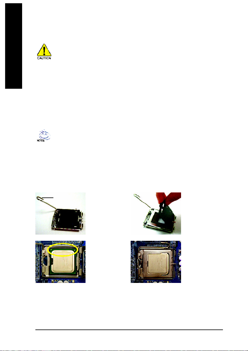
1-3-1 Installation of the CPU
Metal Lever
Fig. 1
Gently lift the m etal
le ver loc ated on the
CPU socke t to the
upright position.
Fig. 2
Re m o v e the pl asti c
cov ering on the CPU
socket.
Fig. 3
Notice the sm all gold
colored triangle located
on the edge of the CPU
socket. Align the
indented co rner of the
posi tion. (Gr asping the CPU firm ly between yo ur
thumb and forefinger, carefully place it into the socket
in a straight and downwards motion. Avoid twisting or
bending m otions that might cause damage to the CPU
during installation.)
GA-8IP775 Series Motherboard - 12 -
Fig. 4
Once the CPU is
properly inserted,
please replace the
plastic co vering and
push the m etal lever
back into its orig inal
position.CPU with the triangl e and gently insert the CPU into
English
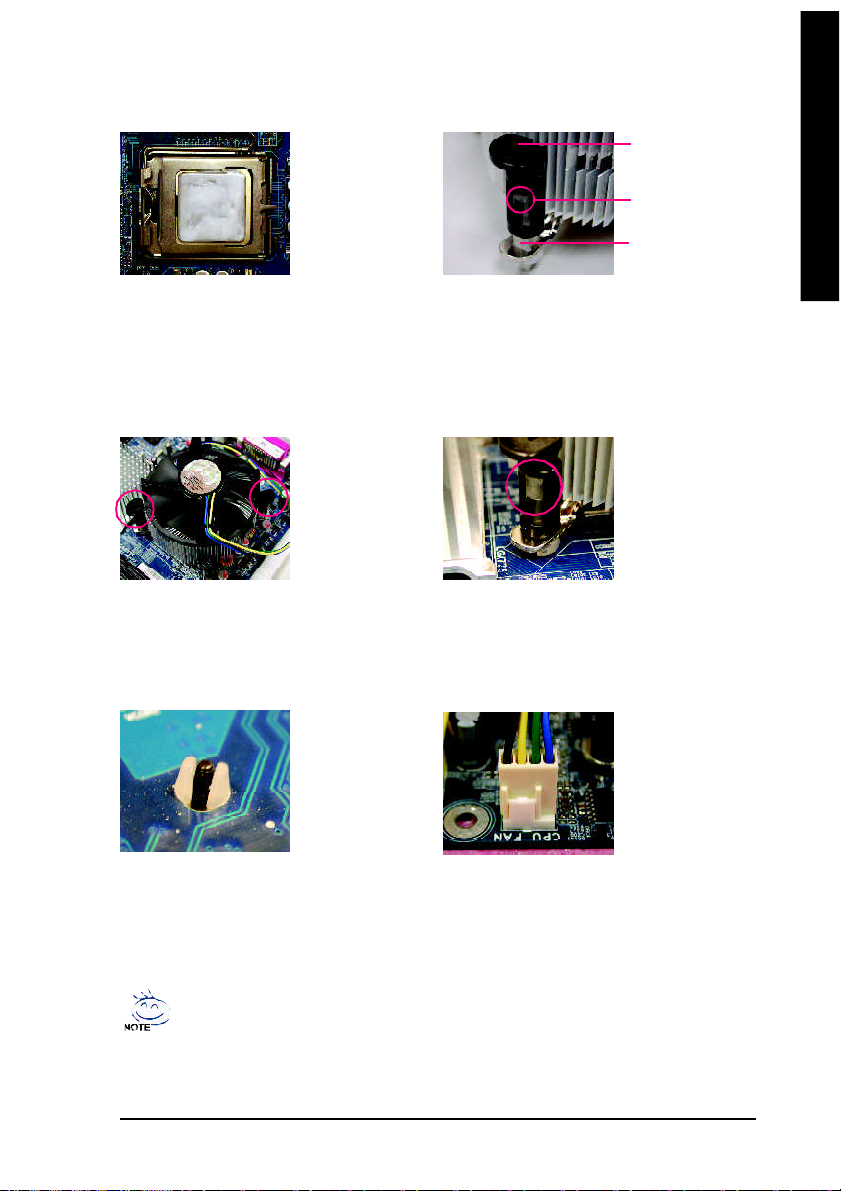
1-3-2 Installation of the Heatsink
Ma le Pus h Pin
The top of Female P ush P in
Fema le Pu sh Pin
Fig.1
Please apply an even layer of heatsink paste on
the surface of the installed CPU.
Fig. 3
Place the hea tsink atop the CPU and m ake sure
the push pins aim to the pin hole on the
m othe rbo ard. Pre ssing down the p ush pins
diagonally.
Fig. 5
Pl ease ch eck the back of m otherboa rd a fter
installing. If the push pin is inserted as the picture,
the i nstallation is complete.
Fig. 2
(Turning the push pin along the direction of arro w is
to remove the heatsink, on the contrary, is to install.)
Please no te the dire ction of arrow sign on the male
push pin doesn't face inwards before installation. (This
instruction is only for Intel boxed fan)
Fig. 4
Please m ake sure the Male and Female push pin are
joined cl osely. (for detailed installa tion instructions,
please refer to the heatsink installation section of the
user manual)
Fig. 6
Fina lly, pl ease attach the po wer conne ctor of the
hea tsink to the C PU fan header loca ted o n the
motherboard.
The heatsink m ay adhere to the CPU as a result of hardening of the heatsink paste.To prevent
such an occurrence, it is suggested that either therm al tape rather than heat sink paste be used for
heat dissipation or using extreme care when removing the heatsink.
Hardware In stallation- 13 -
1-4 Installation of Memory
English
Bef ore ins ta lling th e me mory modu les, p lease comp ly with the fol l owing c o nditi o ns:
1 . Ple ase make su re that t he memo ry used is sup port ed by the mot herbo ard. I t i s rec ommende d tha t
mem ory of s i mi lar capaci ty , specifica tions and br an d b e us ed .
2 . Befo re i ns ta lling or r em oving memory m odules , please m ake sure that the comput er p ower i s swit ched
of f t o prev e nt h ardw are da mage .
3 . Mem ory modul e s h ave a foolp roof inse rtio n des i gn . A mem ory m odul e can be ins ta lled in only one
dir e ction . If y o u a re unabl e to i nsert t he modul e , p lease s w it ch the d irecti on .
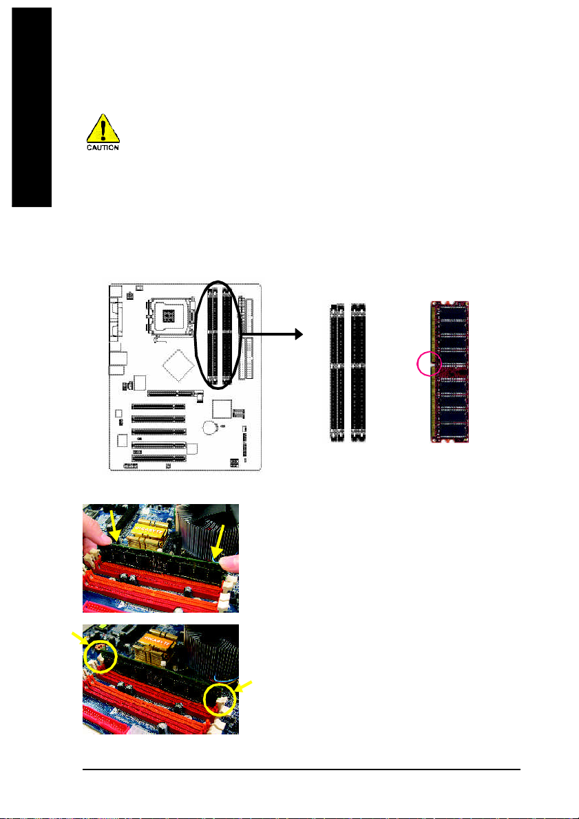
The motherboard supports DDR memory modules, whereby BIOS will automatically detect m emory
capacity and specifications. Mem ory modules are designed so that they can be inserted only in one direction.
The memor y capacity used can differ with each slot.
Notch
DDR
Fig.1
The DIM M socket has a notch, so the DIMM memory module
can only fit in one direction. Insert the DIM M memory m odule
vertically into the DIMM socket. Then push it down.
Fig.2
Close the plastic cl ip at both edges of the DIMM sock ets to
lock the DIMM module.
Reverse the installation steps whe n you wish to rem ove the
DIMM m odule.
GA-8IP775 Series Motherboard - 14 -
English
Dual Channel DDR
GA-8IP775 series supports the Dual Channel Technology. After operating the Dual Channel Technology, the
bandwidth of Memory Bus will add double up to 6.4GB/s.
GA-8IP775 se ries includes 4 DIMM sockets, and each Channel has two DIMM sockets as following:
Channel A : DDR 1, DDR 2
Channel B : DDR 3, DDR 4
If yo u want to operate the Dual Channel Technology, please note the fo llowing explanations due
to the lim itation of Intel chipset speci fications.
1. One/three DDR memory module is installed: The Dual Channel Technology can't operate
when only one DDR memory module is installed.
2. Two DDR memory modules are installed (the same memory size and type): The Dual
Channel Technology will operate when two mem ory modules are inserted individually into
Channel A and B. If you install two memory m odules in the same channel, the D ual Channel
Techn ology will not ope rate.
3. Four DDR memory modules are installed: If you install four m emory modules at the sam e
time, the D ual Channel Technolog y will operate only when those modules have the same
mem ory size and type.
We'll strongly recom mend our user to slot two DDR memory modules into the DIMMs with the same color in
order for D ual Channel Technolo gy to work.
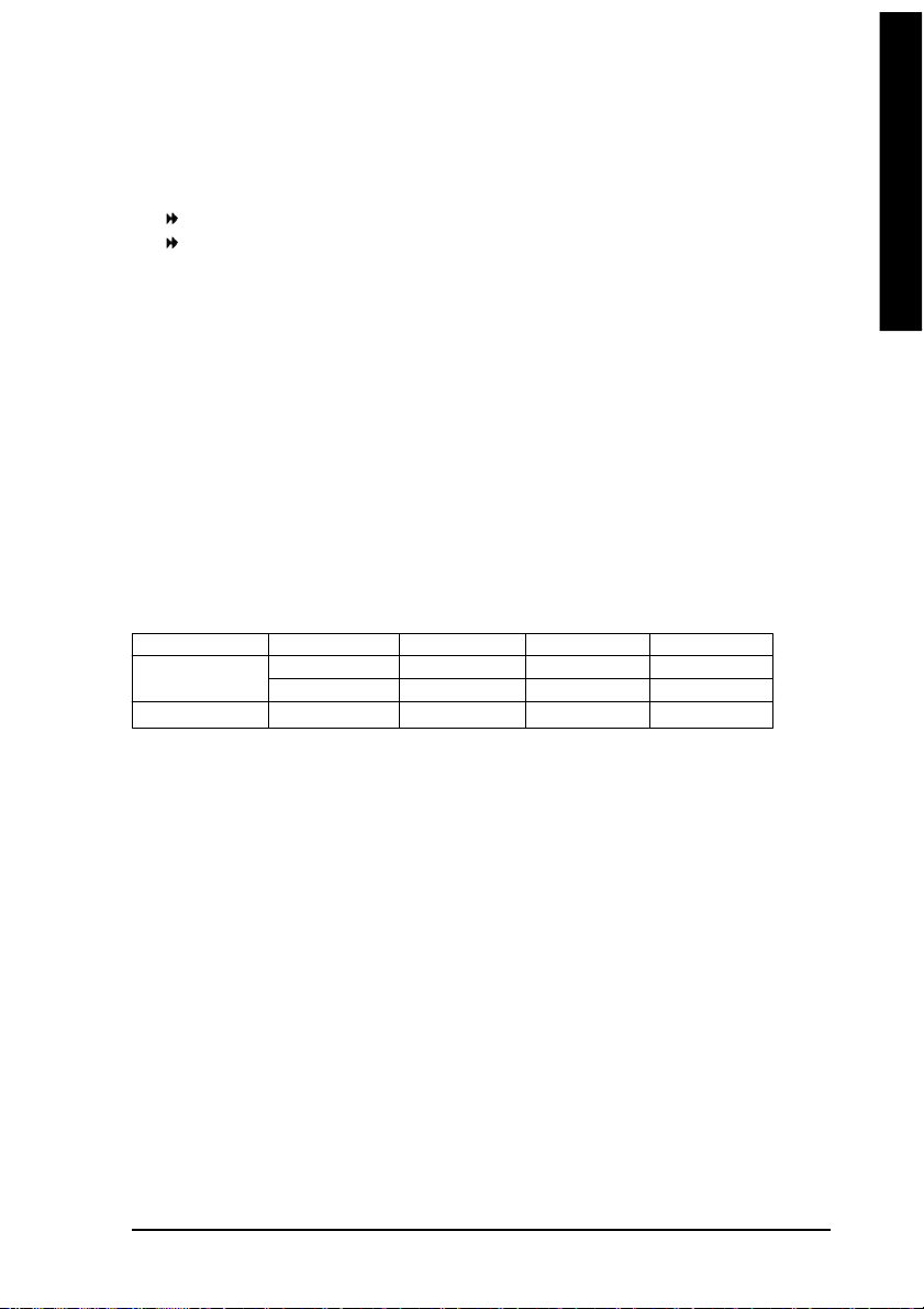
The following table is for Dual Channel Technology combination: (DS: Double Side, SS: Sin gle Side)
DDR 1 DDR 2 DDR 3 DDR 4
2 m emory modules
4 m emory modules
DS/SS X DS/SS X
X DS/SS X DS/SS
DS/SS DS/SS DS/SS DS/SS
Hardware In stallation- 15 -
English
1-5 Installation of Expansion Cards
You can install you r expansion card by following the steps outlined below:
1. Read the related expansion ca rd's instruction doc ument before instal l the expansion card into the
computer.
2. Remove your computer's chassis cover, screws and slot bracket from the computer.
3. Press the expansion card firmly into expansion slot in motherboard.
4. Be sure the metal contacts on the card are indeed seated in the slot.
5. Replace the screw to secure the sl ot bracket of the expansion card.
6. Replace your computer's chassis cover.
7. Power on the computer, if nece ssary, setup BIOS utility of expansion card from BIOS.
8. Install r elated driver fr om the operating system .
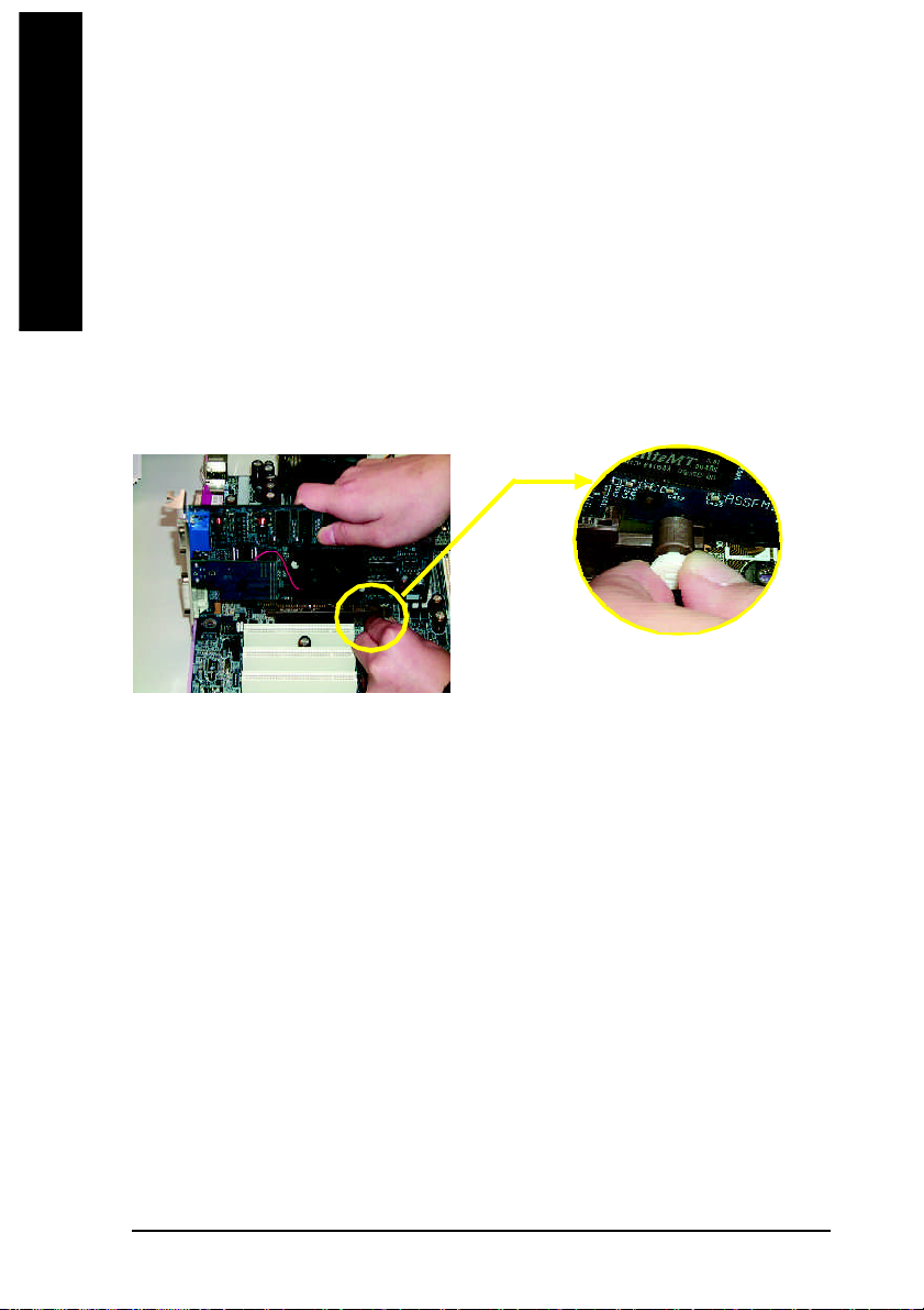
Installi ng a AGP expansi on card:
Please carefully pull out the sm all white-drawable bar
at the end of the AGP slot when y ou try to install/
AGP Card
Uninstall the VGA card. Please align the VGA card to
the onboard AGP slot and press firm ly down on the
slot .M ake sure your VGA card is locked by the sm all
white -drawable bar.
GA-8IP775 Series Motherboard - 16 -
English
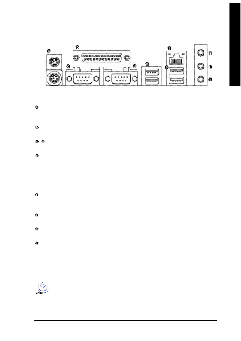
1-6 I/O Back Panel Introduction
(*)
PS/2 Keyboard and PS/2 Mouse Connector
To install a PS/2 port keyboard and mouse, plug the mouse to the upper port (green) and the keyboard
to the lower port (purple).
Parallel Port
The parallel port allows connection of a printer, scanner and other peripheral devices.
/ COM A/COM B (Serial Port)
Connects to serial-based mouse or data processing devices.
USB port
Before you connect your device(s) into USB connector(s), please m ake sure your device(s) such as
USB keyboard, mouse, scanner, zip, speak er...etc. have a standard USB interface.
Also make sure your OS supports USB controller . If your OS does not support USB controller,
please contact OS vendor for possible patch or driver upgrade. For more information please
contact your OS ordevice(s) vendors.
LAN Port (*
The provided Intern et connection is Gigabit Ethernet, providing data transfer sp eeds of
10/100/1000Mbps.
Line In
Devices like CD-ROM, walkman etc. can be connected to Line In jack.
Line Out
Connect the stereo speakers, earphone or front surround channels to this connector.
MIC In
Microphone can be connected to MIC In jack.
)
You can us e audio software to configure 2-/4-/6-/8- channel audio fu nctioning.
(*) Only for GA-8IP775-G.
Hardware In stallation- 17 -
1-7 Connectors Introduction
English
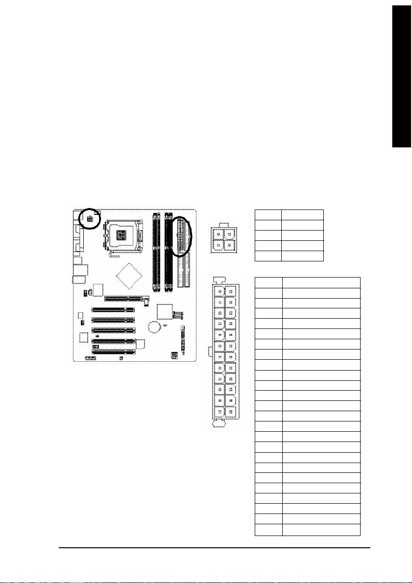
1) ATX_12V
2) ATX
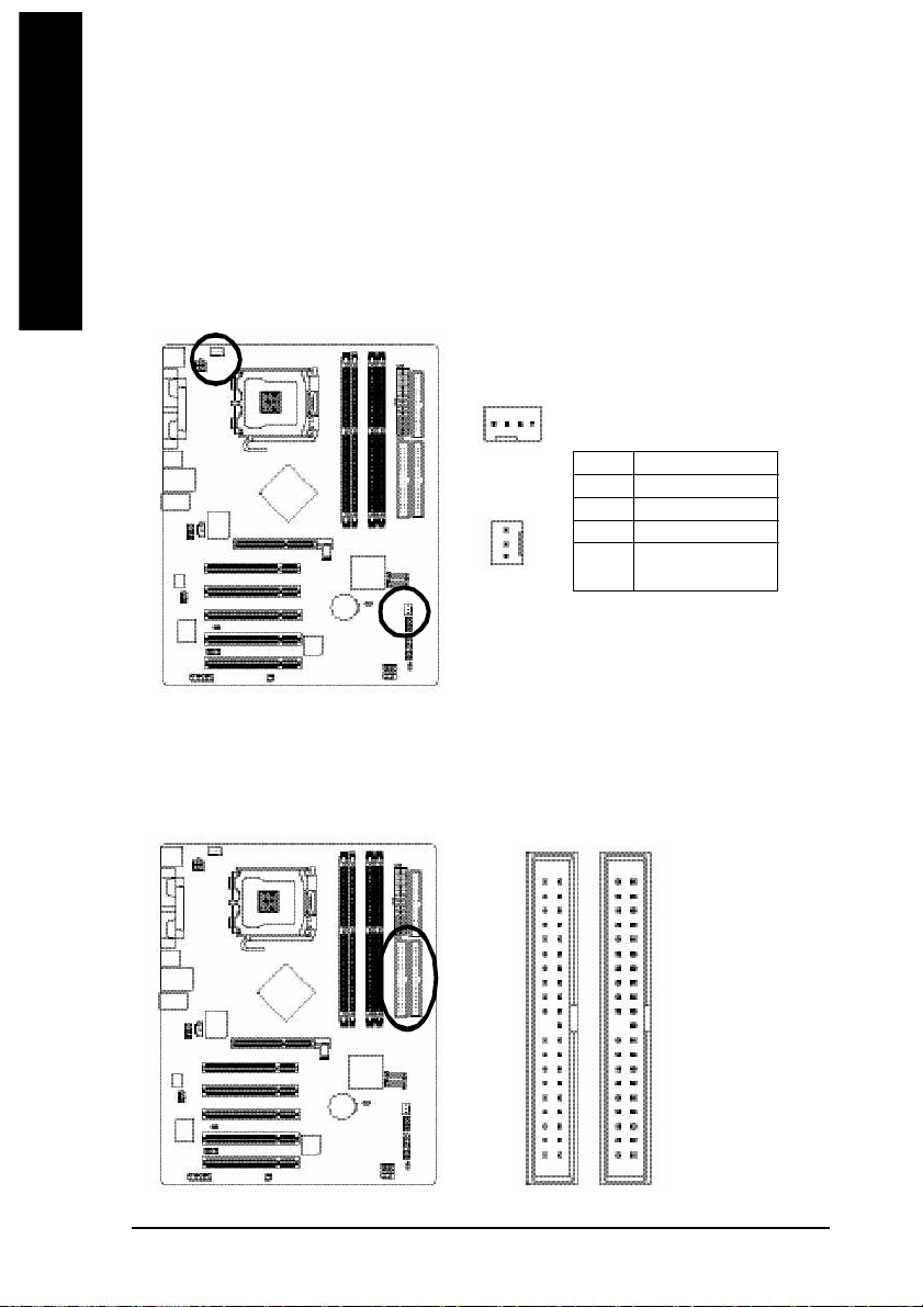
3) CPU_FAN
4) SYS_FAN
5) IDE1/IDE2
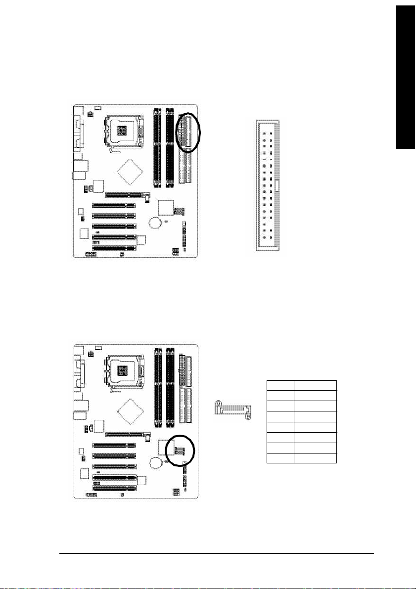
6) FDD
7) SATA0/SATA1
8) PWR_LED
9) F_PANEL
10) F_AUDIO
3
1
12
10
11
18
14
16 20
13
11) SUR_CEN
12) CD_IN
13) SPDIF_IO
14) IR_CIR
15) F_USB1/F_USB2
16) GAME
17) INFO_LINK
18) CI
19) CLR_CMOS
20) BAT
15
6
2
5
19
7
4
17
9
8
GA-8IP775 Series Motherboard - 18 -
English
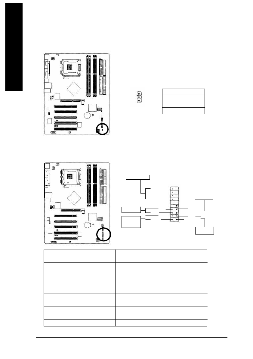
1/2) ATX_12V/ATX (Power Connector)
With the use of the power connector, the power supply can supply enough stable power to a ll the
components on the motherboard. Before connecting the power connector, please make sure that all
components and devices are properly installed. Align the power connector with its proper location on
the m otherboard and connect tightly.
The AT X_12V power connector mainly supplies power to the CPU. If the ATX_12V power
connector is not connected, the syste m will not start.
Caution!
Please use a power sup ply that is abl e to handle th e system voltage requirements. It is
recomm ended that a power supply th at can withstand high power consumption be used (300W or
greater). If a power supply is used that does not provide the required power, the result can lead to an
unstable system or a system that is unable to start.
Please remove the sticker on the m otherboard before plugging in while the ATX power supplier is 24
pins; Other wise, please do not rem ove it.
Pin No. Definition
3
1
1 3
2 4
1 GND
4
2 GND
3 +12V
2
4 +12V
Pin No. Definition
1
1 3.3V
2 3.3V
3 GND
4 VCC
5 GND
6 VCC
7 GND
8 Power Good
9 5V SB(stand by + 5V)
10 +12V
11 +12V
12 3.3V(Only for 2 4pins ATX)
1 2
13 3.3V
14 -12V
15 GND
16 PS_ON(soft On/Off)
17 GND
18 GND
19 GND
20 -5V
21 VCC
22 VCC
23 VCC
24 GND
Hardware In stallation- 19 -
English
3/4) CPU_FAN / SYS_FAN (Cooler Fan Power Connector)
The cooler fan power connector supplies a +12V power voltage via a 3-pin/4-pin (only for CPU_FAN)
power connector and possesses a ful-proof connection design.
Most coolers are designed with color-coded power connector wires. A red power connector wire
indicates a positive connection and requires a +12V power voltage. The black connector wire is
the gr ound wire (GND).
Please remem ber to connect the powe r to the cooler to prevent system overheating and failure.
Caution!
Please rem ember to connect the po wer to the CPU fan to prevent CPU overheating and failure.
1
CPU_FAN
SYS_FAN
1
Pin No. Definition
1 GND
2 +12V
3 Sense
4 Speed Control
(Only for CPU_FAN)
5) IDE1/IDE2 (IDE Connector)
An IDE dev ice connects to the com puter via an IDE connector. One IDE connector can connect to one
IDE cable, and the single IDE cable can then connect to two IDE devices (hard drive or optical drive). If
you wish to connect two IDE devices, please set the jum per on one IDE device as Master and the other
as Slave (for infor mation on settings, please refer to the instructions located on the IDE d evice).
4 0
3 9
GA-8IP775 Series Motherboard - 20 -
2
1
English
6) FDD (Floppy Connector)
The FDD connector is used to co nnect the FD D cable while the other end of the cable connects to the
FDD drive. The types of FDD drives supported are: 360KB, 720KB, 1.2MB, 1.44MB and 2.88MB.
Please connect th e red power connector wire to the pin1 position.
3 4
2
3 3
1
7) SATA0/SATA1 (Serial ATA Connector)
Serial ATA can provide 150MB/s transfer rate. Please refer to the B IOS setting for the Seri al ATA
and install the proper driver in order to work properly.
Pin No. Definition
1 GND
7
1
2 TXP
3 TXN
4 GND
5 RXN
6 RXP
7 GND
Hardware In stallation- 21 -
English
8) PWR_LED
PWR_LED is connect with the system power indicator to indicate wh ether the system is on/off. It will
blink when the system enters suspend mode.
Pin No. Definition
1
1 MPD+
2 MPD-
3 MPD-
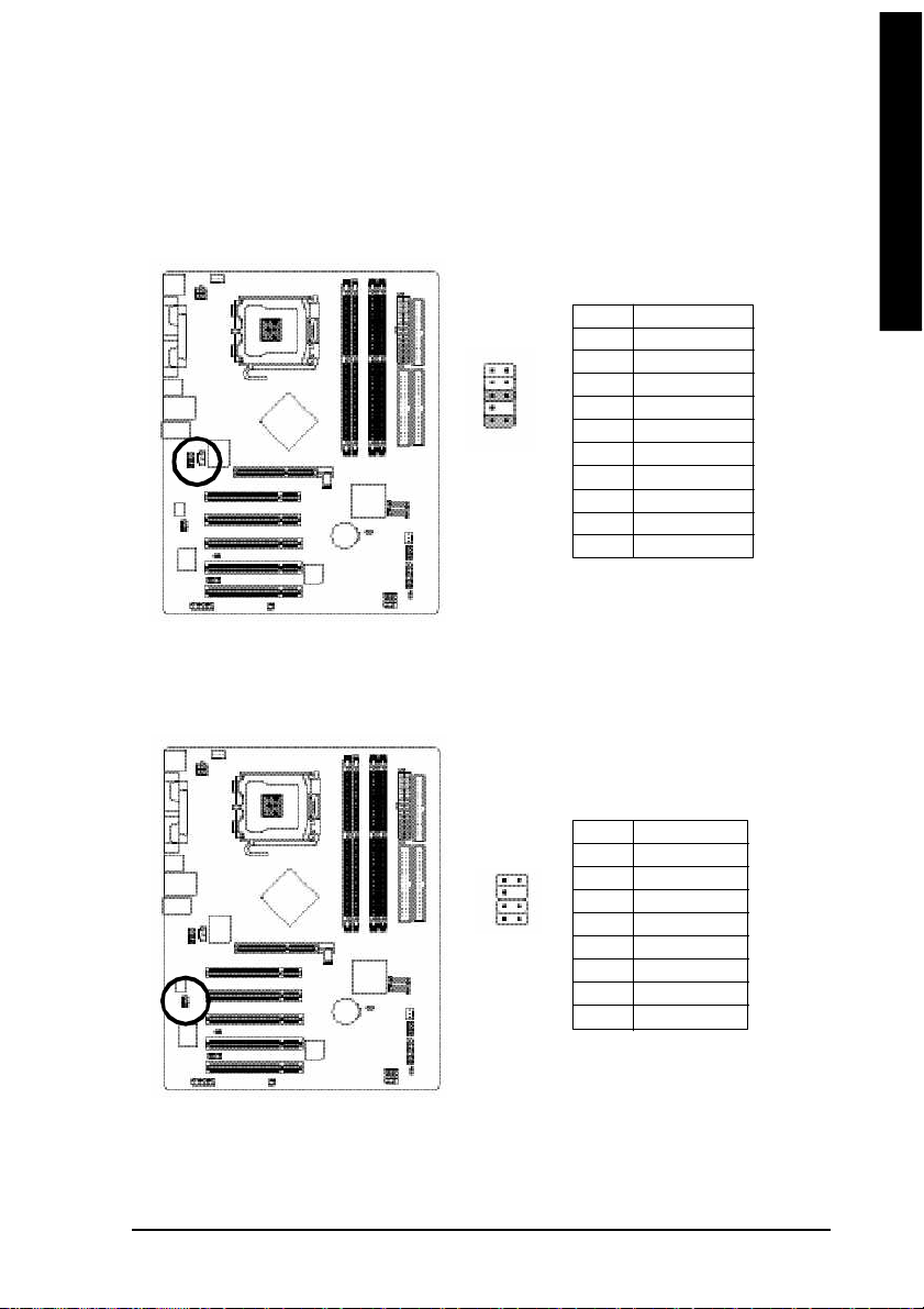
9) F_PANEL (Front Panel Jumper)
Please connect the power LE D, PC peak er, reset switch and p ower switch etc of your chassis front
panel to the F_PANEL connector according to the pin assignment below.
Speaker Connec tor
Power Swit ch
Message LED/
Powe r/
Sleep L ED
SPEAK-
SPEAK+
PW+
MSG+
PW-
MSG-
1 92 0
Reset Swit ch
NC
RES+
RES-
HD -
HD+
1
2
IDE H ard Disk
Acti ve L ED
HD (IDE Hard Disk Active LED) Pin 1: LED anode(+)
(Blue) Pin 2: LED c athode(-)
SPEAK (Speaker Connec tor) Pin 1: VCC(+)
(Amber) Pin 2- Pin 3: NC
Pin 4: Data(-)
RES (Reset Switch) Open: Norm al Operation
(Green) Close: Reset Hardware System
PW (Power Switc h) Open: Norm al Operation
(Red) Close: Power O n/Off
MSG(M essage LED/Power/Sleep LED) Pin 1: LED ano de(+)
(Yellow) Pin 2: LED c athode(-)
NC( Pu rple) NC
GA-8IP775 Series Motherboard - 22 -
English
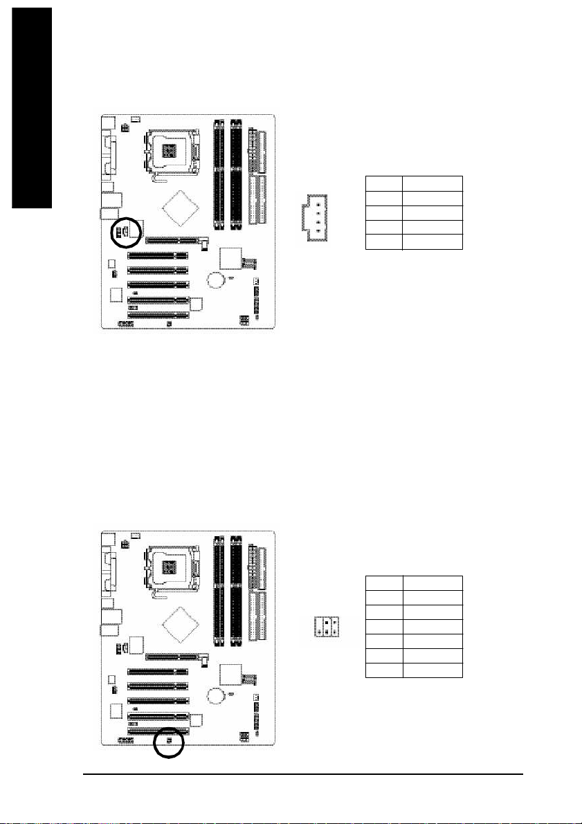
10) F_AUDIO (Front Audio Connector)
If you want to use Front Audio connector, you must remove 5-6, 9-10 Jumper. In order to utilize the
front audio header, your chassis mus t have front audio connector. Also please make sure the pin
assigment on the cable is the sam e as the pin assi gment on the MB header. To find out if the chassis
you are buying support front audio connector, please contact your dealer.Please note, you can have the
alternati ve of using front audio connector or of using rear audio connector to play sound.
Pin No. Definition
1 MIC
2
1
1 0
9
2 GND
3 MIC_BIAS
4 POWER
5 FrontAudio(R)
6 RearAudio(R)
7 Reserved
8 No Pin
9 FrontAudio (L)
10 RearAudio(L)
11) SUR_CEN
Please contact your nearest dealer for optional SUR_CEN cable.
1 2
7 8
Pin No. Definition
1 SUR OUTL
2 SUR OUTR
3 GND
4 No Pin
5 CENTER_OUT
6 BASS_OUT
7 AUX_L
8 AUX_R
Hardware In stallation- 23 -
English
12) CD_IN (CD IN)
Connect CD-ROM or DVD-ROM audio out to the connector.
Pin No. Definition
1
1 CD-L
2 GND
3 GND
4 CD-R
13) SPDIF_IO (SPDIF In/Out)
The SPDIF output is capable of providing digital audio to external speakers or compressed AC3 data to
an external Dolby Digital Decoder. Use this feature only when your stereo system has digital input
function. Use SPDIF IN feature only when your device has digital output func tion.
Be careful with the polarity of the SPDIF_IO connector. Check the pin assignm ent carefully whil e you
connect the SPDIF_IO cable, incorrect connection between the cable and connector will m ake the
device unable to work or even damage it. For optional SPDIF_IO cab le, please contact your local
dealer.
GA-8IP775 Series Motherboard - 24 -
1625
Pin No. Definition
1 VCC
2 No Pin
3 SPDIF
4 SPDIFI
5 GND
6 GND
 Loading...