

Gigabyte GA-6VTX User Manual

FCC Compliance Statement:
DECLARATION OF CONFOR M I TY
Per FCC Part 2 Section 2. 1077(a)
This equipment has been tested and found to
comply with limits for a Class B digital device,
Responsible Party Name: G.B. T. I NC.
Phone/Fax No: (818) 854-9338/ (818) 854-9339
hereby declares that the product
Product Name:
Model Number:
Conforms to the following specificatio ns:
FCC Part 15, Subpart B, Section 15.107(a) and Section 15.109(a),
Class B Digital Device
Supplementary Information:
This device complies with part 15 o f the FCC Rules. Operation is su bject to the
following two conditions: (1) This device may not cause harmful
and (2) this device must accept any inference received, including
that may cause undesired operation.
Representative Person's Name: ERIC LU
Signature:
Address: 18305 Valley Blvd., Suite#A
Mother Board
Date: Jul. 23, 2001
LA Puent, CA 91744
GA-6VTX
Eric Lu
pursuant to Part 15 of the FCC rules. These
limits are designed to provide reasonable
protection against harmful interference in
residential installations. This equipment
generates, uses, and can radiate radio
frequency energy, and if not installed and used
in accordance with the instructions, may cause
harmful interference to radio communications.
However, there is no guarantee that interference
will not occur in a particular installation. If this
equipment does cause interference to radio or
television equipment reception, which can be
determined by turning the equipment off and on, the user is encouraged to try to
correct the interference by one or more of the following measures:
-Reorient or relocate the receiving antenna
-Move the equipment away from the receiver
-Plug the equipment into an outlet on a circuit different from that to which
the receiver is connected
-Consult the dealer or an experienced radio/television technician for
additional suggestions
You are cautioned that any change or modifications to the equipment not
expressly approve by the party responsible for compliance could void Your
authority to operate such equipment.
This device complies with Part 15 of the FCC Rules. Operation is subjected to
the following two conditions 1) this device may not cause harmful interference
and 2) this device must accept any interference received, including interference
that may cause undesired operation.
Declaration of Conformity
We, Manufacturer/Importer
(full address)
G.B.T. Technology Träding GMbH
Ausschlager Weg 41, 1F, 20537 Hamburg, Germany
( description of the apparatus, system, installation to which it refers)
(reference to the specification under which conformity is declared)
in accordance with 89/336 EEC-EMC Directive
EN 55011 Limits and methods of measurement EN 61000-3-2* Disturbances in supply systems caused
of radio disturbance char ac teristics of
industrial, scient ific and medical (ISM electrical equipment “Harmonics”
high frequency equipment
EN55013 Limits and methods of measurement EN61000-3-3* Disturbances in supply systems caused
of radio disturbance char ac teristics of
broadcast receivers and associated electrical equi pment “Voltage fluctuations”
equipment
EN 55014 Limits and methods of measurement EN 50081-1 Generic emission standard Par t 1:
of radio disturbance char ac teristics of Resi dual, commercial and light industr y
household electrical appliances,
portable tools and similar electrical
apparatus Residual, commer c ial and light industr y
EN 55015 Limits and methods of measurement EN 55081-2 Generic emission standard Par t 2:
of radio disturbance char ac teristics of Indust r ial environment
fluorescent lam ps and luminaries
EN 55020 Immunity from radio i nterference of EN 55082-2 Generic immunity standard Part 2:
broadcast receivers and associated Industrial environment
equipment
EN 55022 Limits and methods of measurement ENV 55104 Immunity requirements for household
of radio disturbance char ac teristics of appl iances tools and similar apparatus
information technology equipment
DIN VDE 0855 Cabled distribution systems; Equipment EN 50091- 2 EMC requirements for uninterruptibl e
part 10 for receiving and/or distribution from power systems (UPS)
part 12 sound and television signals
declare that the product
Mother Board
GA-6VTX
is in conformity with
EN60555-2 by household appliances and similar
EN60555-3 by household appliances and similar
EN 50082-1 Generic immunity standard Part 1:
CE marking (EC conformity marking)
The manufacturer also declares the conformity of above mentioned product
with the actual required safety standard s in accordance with LVD 73/23 EEC
EN 60065 Safety requirements for mains operated EN 60950 Safety for informati on technology equipment
electronic and related apparatus for including electr ical business equipment
household and similar general use
EN 60335 Safety of household and similar EN 50091-1 General and Safet y r equirements for
electrical appl iances uninterruptible power system s (UPS )
Signature
Date: Jul. 23, 2001 Name : Rex Lin
(Stamp)
Manufacturer/Importer
Rex Lin
:

6VTX
Socket 370 Processor Motherboard
USER'S MANUAL
Socket 370 Processor Motherboard
REV. 1.2 Second Edition
12ME-6VTX-1202


How This Manual Is Organized
This manual is divided into the following sections:
1) Revision History
2) Item Checklist
3) Features
4) Installation Guide
5) Performance & Block Diagram
6) Suspend to RAM
7) Four Speaker & SPDIF
8) Instant BIOS Flash Utility
9) @BIOS™ & EasyTuneIII™ @BIOS™ & EasyTuneIII™ introduction
10) BIOS Setup
11) Technical Support/RMA Sheet
Manual revision information
Product item list
Product information & specification
Instructions on CPU & Memory Installation
Product performance & block diagram
Instructions STR installation
Four Speaker & SPDIF introduction
Instant BIOS Flash utility introduction
Instructions on setting up the BIOS
software
Document equipment used for after sales
service
12) Appendix
General reference


Table Of Content
Revision History P.1
Item Checklist P.2
Feature Summary P.3
6VTX Motherboard Layout P.5
Installation Guide P.6
Page Index for Connectors / Panel and Jumper Definition P.12
Performance List P.30
Block Diagram P.32
Suspend to RAM Installation P.33
Four Speaker & SPDIF Introduction (Optional) P.38
Instant BIOS Flash Utility Introduction P.44
@BIOSTM Introduction P.46
EasyTuneIIITM Introduction P.47
Page Index for BIOS Setup P.49
Technical Support / RMA Sheet P.78
Appendix P.79

6VTX Motherboard
Revision History
Revision Revision Note Date
1.1 Initial release of the 6VTX motherboard user’s manual. Jul. 2001
1.2 Initial release of the 6VTX motherboard user’s manual. Jul. 2001
1.2 Second release of the 6VTX motherboard user’s manual. Oct. 2001
The author assumes no responsibility for any errors or omissions that may appear in this
document nor does the author make a commitment to update the information contained herein.
Third-party brands and names are the property of their respective owners.
Oct. 15, 2001 Taipei, Taiwan, R.O.C
1

Item Checklist
The 6VTX motherboard
Cable for IDE / floppy device
Diskettes or CD (TUCD) for motherboard driver & utility
6VTX user’s manual
Item Checklist
2
6VTX Motherboard
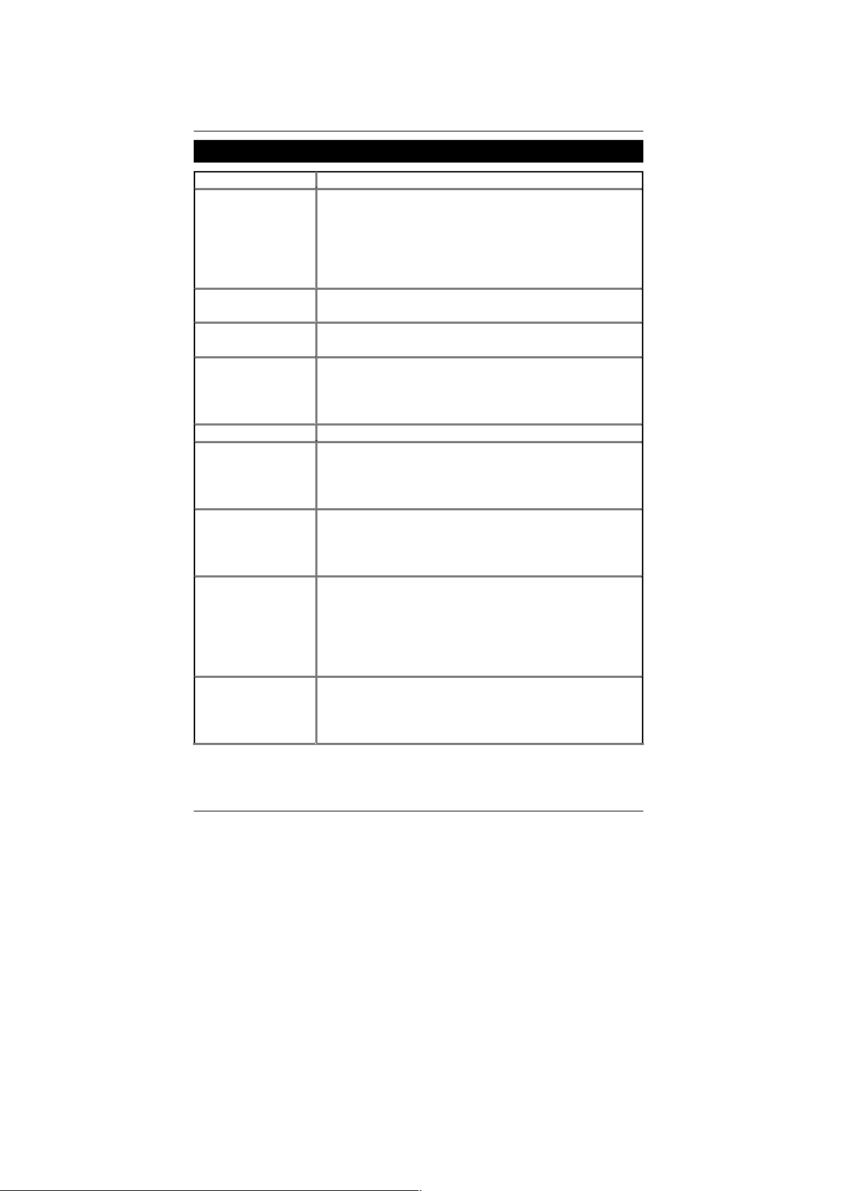
Features Summary
Form Factor 30.5 cm x20.4 cm ATX SIZE form factor, 4 layers PCB.
CPU Socket 370 processor
Chipset
Clock Generator
Memory 3 168-pin DIMM sockets
I/O Control VT82C686B
Slots 1 AG P S lot S upports 4X/2X mode & A GP 2.0 compliant
On-Board IDE Supports PIO mode 3, 4, DMA33/ATA66/ATA100 IDE
On-Board
Peripherals
Hardware Monitor CPU/System fan revolution detect
Supports all new PentiumIII processors (FC-PGA & FC-PGA2
package)
Supports Celeron processors in FC-PGA package
Supports 66/100/133MHz system bus frequency
Can’t Support processor with Vcore above 1.8V
L2 cache in CPU (Depend on CPU)
VT82C694T (VIA Apollo Pro 133T)
VT82C686B
ICS94241AF
66/100/133 MHz system bus speeds
Supports PC-100 / PC-133 SDRAM and VCM SDRAM
Supports up to 1.5GB
Supports only 3.3V SDRAM DIMM
5 PCI Slots Supports 33MHz & PCI 2.2 compliant
1 ISA slot
1 AMR (Audio Modem Riser) slot (Only Secondary)
& ATAPI CD-ROM
2 IDE bus master (UDMA 33/ATA 66/ATA100) IDE
portsfor up to 4 ATAPI devices
1 floppy port supports 2 FDD with 360K, 720K, 1.2M,
1.44M and 2.88M bytes
1 parallel port supports Normal/EPP/ECP mode
2 serial ports (COM A & COM B)
4 USB ports
1 IrDA connector for IR
CPU/System temperature detect
System voltage detect
CPU overheat shutdown detect
To be continued…
3

Features Summary
On-Board Sound Creative CT5880 sound (Optional)
AC’97 CODEC
Line In/Line Out/Mic In/AUX In (Optional)/CD In/
TEL (Optional)/Game Port/ SPDIF (Optional)
/Four Speaker (Optional)
BIOS Licensed AMI BIOS, 2M bit flash ROM
PS/2 Connector PS/2 keyboard interface and PS/2 mouse interface
Additional Features Supports Wake-on-LAN (WOL)
STR (Suspend-To-RAM)
Supports Internal / External modem wake up
Includes 3 fan power connectors (Power Fan is optional)
Poly fuse for keyboard/USB/Mouse over-current
protection
Support @BIOS™ and EasyTuneIII™
4
6VTX Motherboard
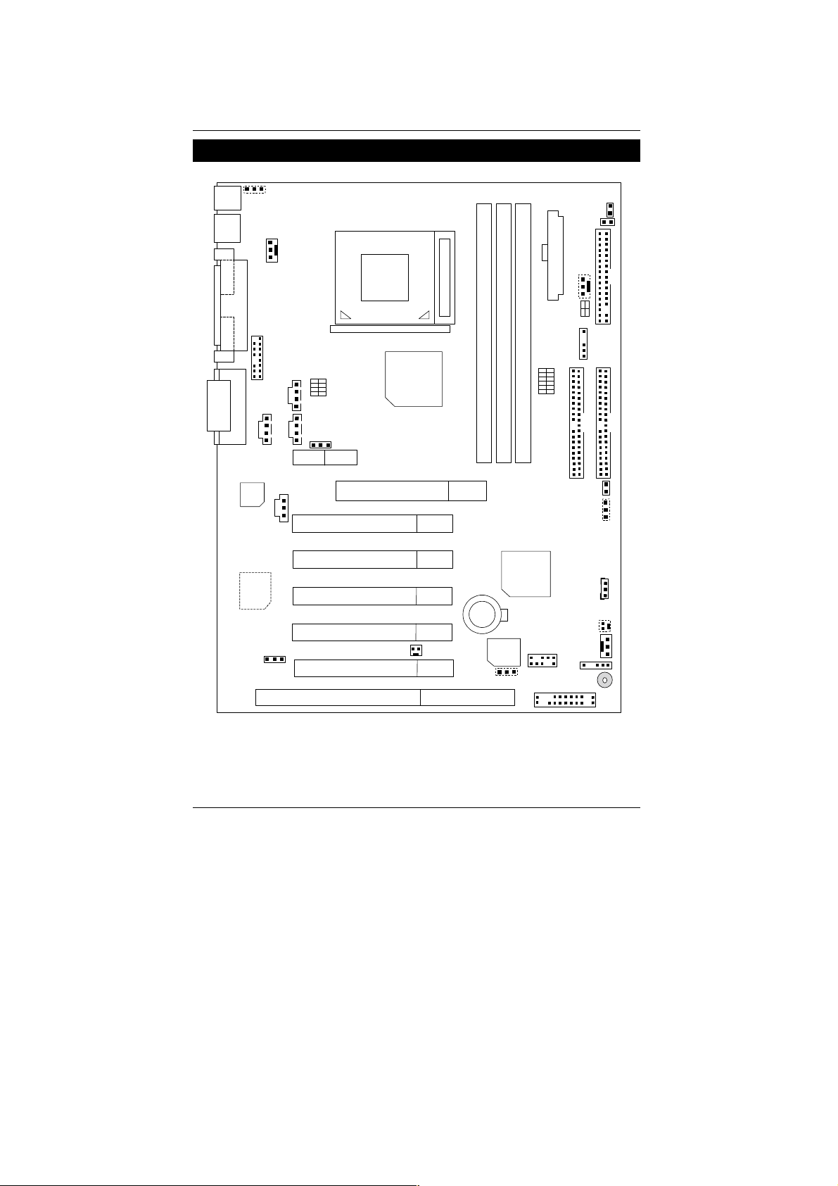
6VTX Motherboard Layout
KB/MS
RUSB_ON
USB1
CPU_FAN
PGA 370
COM A
LPT
CPU
LED2
S_LED
ATX Power
PWR_FAN
SW4
COM B
Game & Audio
AC97
Creative
CT5880
AUDIO_EN
F_AUDIO
AUX_IN
ISA
SMB
DIMM2
CLK_SW
DIMM3
CASE_OPEN
CLR_CMOS
USB2
F_PANEL
TEL
CLK_RATIO
CD_IN
JP18
AMR
AGP
SPDIF
PCI1
PCI2
PCI3
PCI4
PCI5
VT82C694T
6VTX
S_IRQ
DIMM1
VT82C686B
BAT1
BIOS
BIOS_WP
Floppy
IDE1
IDE2
WOL
WOR
SYS_FAN
IR
BZ1
5

Installation Guide
Installation Guide
Getting Started
WARNING!
Computer motherboards and expansion cards contain very delicate Integrated
Circuit (IC) chips. To protect them against damage from static electricity, you
should follow some precautions whenever you work on your computer.
1. Unplug your computer when working on the inside.
2. Use a grounded wrist strap before handling computer components. If you do not have one,
touch both of your hands to a safely grounded object or to a metal object, such as the power
supply case.
3. Hold components by the edges and try not touch the IC chips, leads or connectors, or other
components.
4. Place components on a grounded antistatic pad or on the bag that came with the
components whenever the components are separated from the system.
5. Ensure that the ATX power supply is switched off before you plug in or remove the ATX power
connector on the motherboard.
Installing the motherboard to the chassis…
If the motherboard has mounting holes, but they don’t line up with the holes on the base and there
are no slots to attach the spacers, do not become alarme d you can still attach the spacers to the
mounting holes. Just cut the bottom portion of the spacers (the spacer may be a little hard to cut off,
so be careful of your hands). In this way you can still attach the motherboard to the base without
worrying about short circuits. Sometimes you may need to use the plastic springs to isolate the
screw from the motherboard PCB surface, because the circuit wire may be near by the hole. Be
careful, don’t let the screw contact any printed circuit write or parts on the PCB that are near the
fixing hole, otherwise it may damage the board or cause board malfunctioning.
6

6VTX Motherboard
To set up your computer, you must complete the following steps:
Step 1 - Set system jumpers
Step 2- Install the Central Processing Unit (CPU)
Step 3-Install memory modules
Step 4-Install expansion cards
Step 5-Connect ribbon cables, cabinet wires, and power supply
Step 6-Set up BIOS software
Step 7-Install supporting software tools
Step 2
Step 3
Step 5
Step 5
Step 1
Step 4
Step 1
Step 5
7
Installation Guide
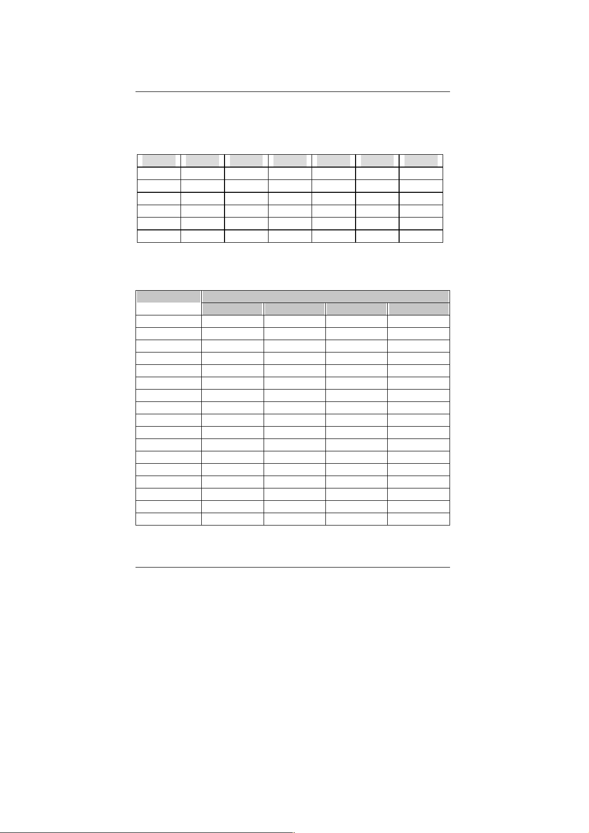
CPU Speed Setup
The system bus speed is selectable at 66,100,133MHz and Auto. The user can select the system
bus speed by DIP switch CLK_SW & CLK_RATIO.
CLK_SW: O : ON, X : OFF
CPU 1 2 3 4 5 6
AUTO X X O O O O
66 O O O O X X
100 O X O O X X
133 X X O O X X
*137 X X X O X X
*142 X X X X X X
(* These speed settings are not guaranteed)
CLK_RATIO: O : ON, X : OFF
DIP SWITCH FREQ. RATIO
1 2 3 4
X3 O X O O
X3.5 X X O O
X4 O O X O
X4.5 X O X O
X5 O X X O
X5.5 X X X O
X6 O O O X
X6.5 X O O X
X7 O X O X
X7.5 X X O X
X8 O O X X
X8.5 O X O O
X9 X X O O
X9.5 X O O O
X10 X O X X
X10.5 O O X O
X11 O X X X
8

6VTX Motherboard
X11.5 X O X O
X12 O X X O
X13 X X X O
X14 O O O X
X15 X O O X
X16 O X O X
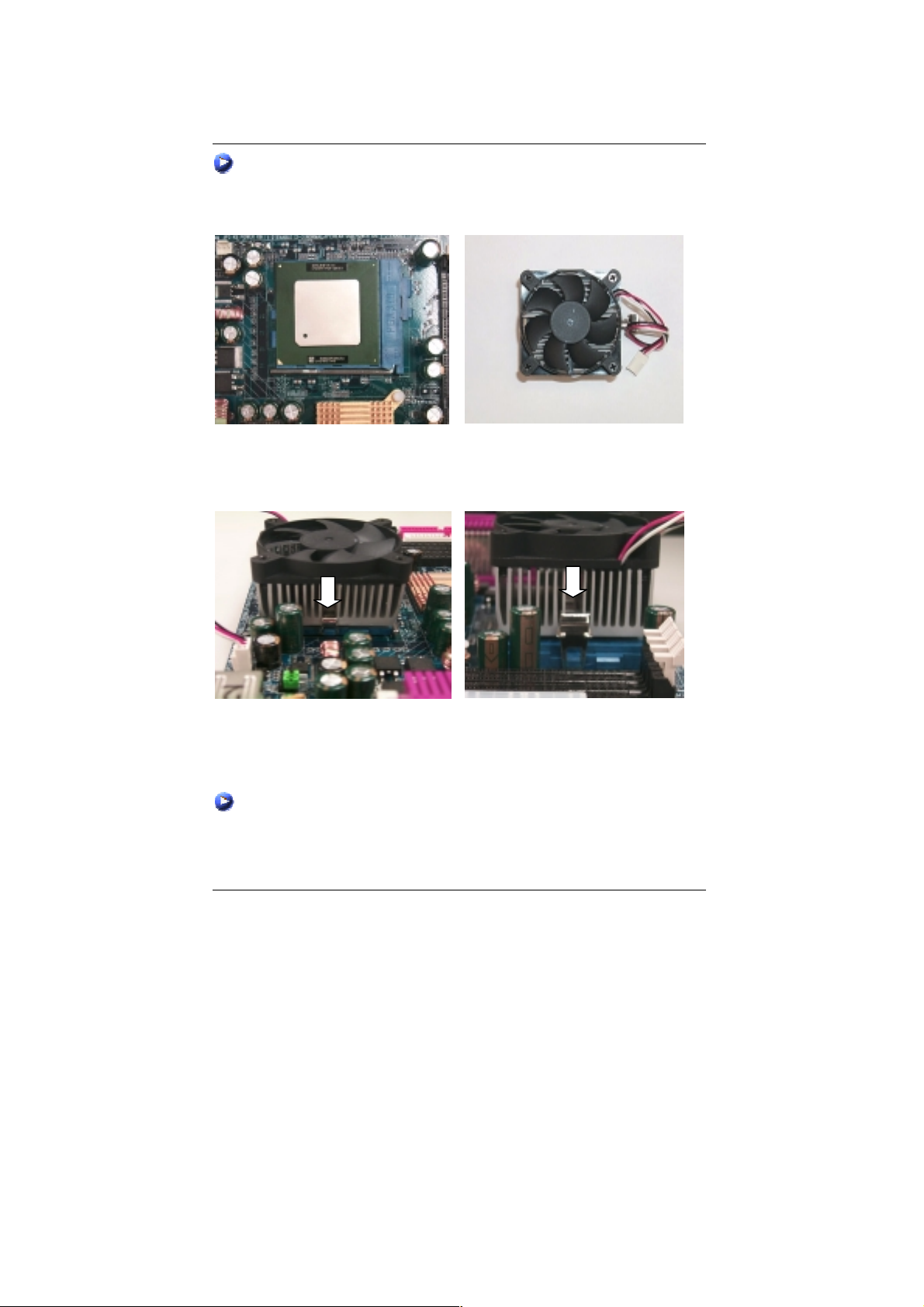
CPU Installation
Please make sure the CPU type and speed is supported by your motherboard.
For example: The newest Pentium III processor (FC-PGA2 package).
CPU Top View
Socket Actuation Lever
1.Pull the lever out and lift it up.
CPU Bottom View
2.The notched corner should point toward the
end of the lever. The CPU will only fit in the
orientation as shown.
9
Installation Guide
CPU Heat Sink Installation:
Beware: Please check that the heat sink is in good contact with the CPU before you turn on your
system. Poor contact will cause over heat with might cause damage to your
processor!
3.Align CPU and insert it
(Please refer to your heatsink installation
manual for application of thermal grease to
provide better heat conduction between your
CPU and heatsink.)
5.Hook one end of the cooler bracket to the CPU socket.
6. Hook the other end of the cooler bracket to the CPU socket.
7. Make sure the CPU fan is plugged to the CPU fan connector, than install complete.
(Please refer to the cooler’s installation manual for detailed installation steps)
4.Use compliant fan approved by Intel.
10
6VTX Motherboard
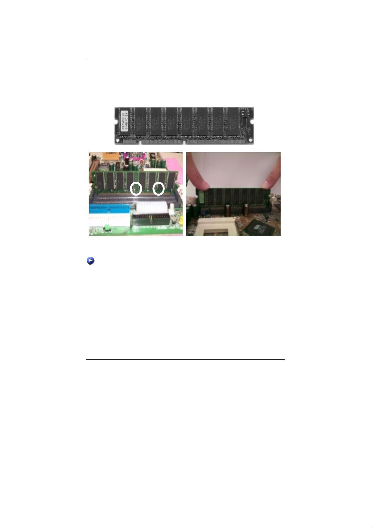
Memory Installation
The motherboard has 3 dual inline memory module (DIMM) s ockets support 6 banks . T he BIOS
will automatically detects memory type and size. To install the memory module, just push it
vertically into the DIMM Slot .The DIMM module can only fit in one direction due to the two notch.
Memory size can vary between sockets.
SDRAM
1. The DIMM slot has two notch, so the DIMM
memory module can only fit in one direction.
2. Insert the DIMM memory module vertically
into the DIMM slot. Then push it down.
3. Close the plastic clip at both edges of the DIMM slots to lock the DIMM module.
Reverse the installation steps when you wish to remove the DIMM module.
11

Installation Guide
Page Index for Connectors/Panel and Jumper Definition Page
Connectors P.13
ATX Power P.13
AUX_IN (AUX_IN) [Optional] P.19
CPU_FAN (CPU Fan) P.17
CD_IN (CD Audio Line In) P.19
COM A / COM B / LPT Port P.13
Floppy Port P.15
F_AUDIO (Front Audio) P.16
Game & Audio Port P.17
IDE 1(Primary)/ IDE 2(Secondary) Port P.16
IR (IR Header) P.22
KB/MS (PS/2 Keyboard & PS/2 Mouse Connector) P.14
PWR_FAN (Power Fan) [Optional] P.18
SMB (External SMBUS Device Connector) [Optional] P.20
S_LED/LED2 (STR LED Connector & DIMM LED) P.22
S_IRQ (Serial IRQ) [Optional] P.23
SPDIF (Optional) P.24
SW4 (V_DIMM OVER Voltage) P.23
SYS_FAN (System Fan) P.18
TEL (Optional) P.20
USB1 (Rear USB Connector) P.14
USB2 (Front USB Port) P.15
WOL (Wake on LAN) P.21
WOR (Ring Power On) [Optional] P.21
Panel and Jumper Definition P.25
AUDIO_EN (Onboard Sound Function Selection) [Optional] P.28
BAT1 (Battery) P.29
BIOS_WP (BIOS Write Protection) [Optional] P.27
CLR_CMOS (Clear CMOS Function) [Optional] P.26
CASE_OPEN (Case Open) [Optional] P.27
F_PANEL (2x11 Pins Jumper) P.25
JP18 (AMR Selection) [Optional] P.28
RUSB_ON (Front/Rear USB Device Wake up Selection) P.26
12

6VTX Motherboard
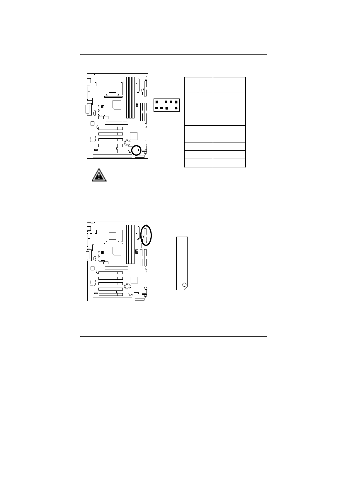
Connectors
ATX Power
Please note:
AC power cord should only be connected to your power supply unit after ATX
power cable and other related devices are firmly connected to the mainboard.
COM A / COM B / LPT Port
111
1020
Pin No. Definition
3,5,7,13,15-17 GND
1,2,11 3.3V
4,6,19,20 VCC
10 +12V
12 -12V
18 -5V
8 Power Good
9 5V SB (stand by+5V)
14 PS-ON(Soft On/Off)
LPT Port
COM A
Please note:
This mainboard supports 2 standard COM ports and 1 LPT port. Device like printer
can be connected to LPT port, mouse and modem etc can be connected to COM
ports.
COM B
13

KB/MS: PS/2 Keyboard & PS/2 Mouse Connector
Connectors
PS/2 Keyboard
Please note:
This mainboard supports standard PS/2 keyboard and PS/2 mouse interface
connector.
USB1: Rear USB Connector
PS/2 Mouse
6
4
2
5
1
5
3
1
8
6
7
2
3
4
PS/2 Mouse/ Keyboard
Pin No. Definition
1 Data
2 NC
3 GND
4 Power
5 Clock
6 NC
Pin No. Definition
1 USB Power
2 USB D03 USB D0+
4 GND
5 USB Power
6 USB D17 USB D1+
8 GND
Please note:
Before you connect your device(s) into USB connector(s), please make sure your
device(s) has a standard USB interface like, USB keyboard, mouse, scanner, zip,
buzzer… Also make sure your OS supports USB controller (Win 95 w/ USB
supperment, Win98, Windows 2000, Windows ME, Win NT w/ SP 6). If your OS
does not support USB controller, please contact OS vendor for passible patch or
driver upgrade. For more information please contact your OS or device(s) vendors.
14
6VTX Motherboard
USB2: Front USB Port
Please note:
Be careful with the polarity of the front panel USB connector. Check the pin
assignment while you connect the front panel USB cable. Please contact your
nearest dealer for optional front panel USB cable.
Floppy Port
Pin No. Defin itio n
1 POWER
2
10
2 GND
3 USB D2-
1
9
4 NC
5 USB D2+
6 USB D3+
7 NC
8 USB D39 GND
10 POWER
Red Line
15

IDE1 (Primary), IDE2 (Secondary) Port
IDE 1 IDE 2
Connectors
F_AUDIO: Front Audio
Please note : If you want to use “Front Audio” connector, you must move
11-12,13-14 Jumper.
In order to utilize the front audio header, your chassis must have front audio
connector. Also please make sure the pin assigment on the cable is the same as
the pin assigment on the MB header. To find out if the chassis you are buying
support front audio connector, please contact your dealer.
16
2
15
1
Red Line
Pin No. Definition
1 Incase speaker (R)
2 Incase speaker (L)
3,
4,5,6,10,15
7 +12V
8,16 NC
9 MIC
11 Front Audio (R)
13 Front Audio (L)
12 Rear Audio (R)
14 Rear Audio (L)
GND
16

6VTX Motherboard
Game & Audio Port
Game
Port
Please note: Line Out 1: Line Out or SPDIF (The SPDIF output is capable of
providing digital audio to external speakers or compressed AC3 data to an
external Dolby digital decoder). To enable SPDIF, simply insert SPDIF connector
into Line Out1. Line Out1 will become SPDIF Out automatically. (see page 41 for
more information).
To enable Four Speaker (for Creative 5880 audio only), simply follow instructions
on page 38 and Line In will become Line Out2 to support second pair of stereo
speakers.
CPU_FAN: CPU Fan
Line Out 1
Line In/Line Out 2
1
Pin No. Definition
1 GND
2 +12V
3 SENSE
MIC In
Please note:
A proper installation of the CPU cooler is essential to prevent the CPU from
running under abnormal condition or damaged by overheating.
17

PWR_FAN: Power Fan (Optional)
Connectors
1
Pin No. Definition
1 GND
2 +12V
3 SENSE
SYS_FAN: System Fan
1
Pin No. Definition
1 GND
2 +12V
3 SENSE
18

6VTX Motherboard
CD_IN: CD Audio Line In
AUX_IN: AUX_IN (Optional)
1
Pin No . Definition
1 CD-L
2 GND
3 GND
4 CD-R
1
Pin No. Definition
1 AUX-L
2 GND
3 GND
4 AUX-R
19

TEL: The connector is for Modem with internal voice connector
(Optional)
1
Pin No. Definition
1 Signal-In
2 GND
3 GND
4 Signal-Out
SMB: External SMBUS Device Connector (Optional)
Connectors
Pin No. Definition
1 SMB CLK
1
2 NC
3 GND
4 SMB DATA
5 +5V
20

6VTX Motherboard
WOL: Wake On LAN
1
Pin No. Definition
1 +5V SB
2 GND
3 Signal
WOR: Ring Power On (Internal Modem Card Wake Up) [Optional]
1
Pin No . Definition
1 Signal
2 GND
21

S_LED/LED2: STR LED Connector & DIMM LED
DIMM LED
+
1
STR LED Connector External
Please note:
Do not remove memory modules while DIMM LED is on. It might cause short or
other unexpected damages due to the 3.3V stand by voltage. Remove memory
modules only when STR function is disabled by jumper and AC Power cord is
disconnected.
IR: IR Header
Connectors
1
Pin No. Definition
1 VCC (+5V)
2 NC
3 IR Data Input
4 GND
5 IR Data Output
Please note:
Be careful with the polarity of the IR connector while you connect the IR. Please
contact you nearest dealer for optional IR device.
22

6VTX Motherboard
S_IRQ: Serial IRQ (Optional)
SW4: V_DIMM OVER Voltage
1
Pin No. Definition
1 Signal
2 GND
1 2
ON
O:ON, X:OFF
SW1 SW2
3.6V ON ON
3.5V ON OFF
3.4V OFF ON
3.3V (Default) OFF OFF
Please note:
Provide SDRAM voltage override function. Incorrect using may cause your
SDRAM broken. For power End-User only!
23
 Loading...