

Page 1
Phone/Fax No: (818) 854- 9338/ (818) 854-9339
hereby declare s that the product
Product Name:
Model Number:
Mother Board
Signature:
GA- 6OXM7
FCC Compliance Statement:
DECLARATION OF CONFORMITY
Per FCC Part 2 Section 2. 1077(a)
This equipment has been tested and found to
comply with limits for a Class B digital device,
Responsible Party Name: G.B.T. INC.
Address: 18305 Valley Blvd., Suite#A
LA Puent, CA 91744
pursuant to Part 15 of the FCC rules. These
limits are designed to provide reasonable
protection against harmful interference in
residential installations. This equipment
generates, uses, and can radiate radio
Conforms to the following specifications:
FCC Part 15, Subpart B, Section 15.107(a) and Section 15.109(a),
Class B Digital Device
Supplementary Information:
This device complies with part 15 of the FCC Rules. Operation is subject to the
following two conditions: (1) This device may not cause harmful
and (2) this device must accept any inference received, including
that may cause undesired operation.
Representative Person's Name: ERIC LU
Eric Lu
Date: Jun. 13, 2000
frequency energy, and if not installed and used
in accordance with the instructions, may cause
harmful interference to radio communications.
However, there is no guarantee that interference
will not occur in a particular installation. If this
equipment does cause interference to radio or
television equipment reception, which can be
determined by turning the equipment off and on, the user is encouraged to try to
correct the interference by one or more of the following measures:
-Reorient or relocate the receiving antenna
-Move the equipment away from the receiver
-Plug the equipment into an outlet on a circuit different from that to which
the receiver is connected
You are cautioned that any change or modifications to the equipment not
expressly approve by the party responsible for compliance could void Your
authority to operate such equipment.
This device complies with Part 15 of the FCC Rules. Operation is subjected to
the following two conditions 1) this device may not cause harmful interference
and 2) this device must accept any interference received, including interference
that may cause undesired operation.
-Consult the dealer or an experienced radio/television technician for
additional suggestions
Page 2
Declaration of Conformity
We, Manufacturer/Importer
(full address)
G.B.T. Technology Träding GMbH
Ausschlager Weg 41, 1F, 20537 Hamburg, Germany
( description of the apparatus, system, installation to which it refers)
(reference to the specification under which conformity is declared)
in accordance with 89/336 EEC-EMC Directive
EN 55011 Limits and methods of measurement EN 61000-3-2* Disturbances in supply systems caused
of radio disturbance characteristics of EN60555-2 by household appliances and similar
industrial, scientific and medical (ISM electrical equipment “Harmonics”
high frequency equipment
EN55013 Limits and methods of measurement EN61000-3-3* Disturbances in supply systems caused
of radio disturbance characteristics of EN60555-3 by household appliances and similar
broadcast receivers and associated electrical equipment “Voltage fluctuations”
equipment
EN 55014 Limits and methods of measurement EN 50081-1 Generic emission standard Part 1:
of radio disturbance characteristics of Residual, commercial and light industry
household electrical appliances,
portable tools and similar electrical EN 50082-1 Generic immunity standard Part 1:
apparatus Residual, commercial and light industry
EN 55015 Limits and methods of measurement EN 55081-2 Generic emission standard Part 2:
of radio disturbance characteristics of Industrial environment
fluorescent lamps and luminaries
EN 55020 Immunity from radio interference of EN 55082-2 Generic immunity standard Part 2:
broadcast receivers and associated Industrial environment
equipment
EN 55022 Limits and methods of measurement ENV 55104 Immunity requirements for household
of radio disturbance characteristics of appliances tools and similar apparatus
information technology equipment
DIN VDE 0855 Cabled distribution systems; Equipment EN 50091- 2 EMC requirements for uninterruptible
part 10 for receiving and/or distribution from power systems (UPS)
part 12 sound and television signals
declare that the product
Mother Board
GA-6OXM7
is in conformity with
CE marking (EC conformity marking)
The manufacturer also declares the conformity of above mentioned product
EN 60065 Safety requirements for mains operated EN 60950 Safety for information technology equipment
electronic and related apparatus for including electrical business equipment
household and similar general use
EN 60335 Safety of household and similar EN 50091-1 General and Safety requirements for
electrical appliances uninterruptible power systems (UPS)
Signature
with the actual required safety standards in accordance with LVD 73/23 EEC
Date: Jun. 13, 2000 Name : Rex Lin
(Stamp)
Manufacturer/Importer
Rex Lin
:
Page 3

6OXM7 系列
Socket 370 處理器主機板
中文安裝手冊
Socket 370 處理器主機板
REV.2.0 Second Edition
R-20-02-001127C
Page 4

Page 5

使用手冊之組織架構
此安裝手冊是依下列章節組織而成:
1) 版本修改摘要
2) 清點附件
3) 特色彙總
4) 硬體設定
5) 效能測試和晶片組功能方塊
圖
6) Suspend to RAM 及 Dual BIOS STR 及 Dual BIOS安裝說明
7) Four Speaker 及 SPDIF Four Speaker 及 SPDIF安裝說明
8) @BIOSTM 及EasyTuneIIITM @BIOSTM及 EasyTuneIIITM 功能介紹
9) BIOS 功能設定 BIOS功能設定指南
10) 附錄
使用手冊版本修改資訊
產品盒內附件清單
主機板詳細資訊和規格
主機板安裝指南
主機板效能測試結果和晶片組功能
方塊圖
參考資料
Page 6

Page 7

目 錄
版本修改摘要
清點附件
特色彙總
6OXM7系列主機板的元件配置圖 P.5
CPU 速度設定 / 插座及接腳設定的快速安裝指南 P.6
效能測試
晶片組功能方塊圖
安裝Suspend to RAM 功能(選購) P.32
雙BIOS(Dual BIOS)功能介紹 (選購) P.38
Four Speaker 及 SPDIF功能介紹 (選購) P.45
@BIOSTM 功能介紹
EasyTuneIIITM功能介紹
P.1
P.2
P.3
P.30
P.31
P.50
P.51
記憶體安裝指南
BIOS 組態設定目錄 P.53
附錄
P.52
P.90
Page 8
6OXM7 系列主機板
版本修改摘要
版本 修改摘要 日期
1.2
1.2
2.0
2.0
本手冊所有提及之商標與名稱皆屬該公司所有。
本手冊若有任何內容修改,恕不另行通知。
6OXM7系列主機板中文安裝手冊首版發行。
6OXM7系列主機板中文安裝手冊第二版發行。
6OXM7系列主機板中文安裝手冊首版發行。
6OXM7系列主機板中文安裝手冊第二版發行。
2000年11月27日 台北,台灣
Jun.2000
Jul.2000
Aug.2000
Nov.2000
1
Page 9

Page 10

清點附件
þ 6OXM7 系列主機板一片
þ 軟、硬碟插座排線各一條
þ 主機板驅動程式光碟片(IUCD)
þ 6OXM7 系列中文使用手冊
清點附件
3
Page 11

Page 12

6OXM7 系列主機板
特色彙總
規格 Ÿ 主機板採四層設計ATX規格30.5 公分 x 21.5 公分
CPU
晶片組 Ÿ Intel 815 HOST / AGP / SDRAM Controlle r
時脈產生器
記憶體 Ÿ 4 168-pin DIMM插槽 (DIMM4 為選購)
I/O 控制器 Ÿ IT8712
擴充槽
內建IDE
內建周邊設備 Ÿ 1 個軟碟插座支援兩台磁碟機
硬體監控 Ÿ CPU/電源供應器/系統風扇轉速偵測
內建音效
Ÿ Socket 370 處理器
Intel Pentium!!! 100/133MHz FSB, FC-PGA
Intel CeleronTM 66MHz FSB, FC-PGA
nd
Ÿ 2
Ÿ 82801AA I/O Controller Hub (ICH)
Ÿ ICS 9250-25
Ÿ 66/100/133 MHz system bus speeds
Ÿ 支援 PC-100 / PC-133 SDRAM
Ÿ 最大支援到 512MB
Ÿ 只支援 3.3V SDRAM DIMM
Ÿ 1 AGP擴充槽支援4X mode 及 AGP 2.0 compliant
Ÿ 1 DFP /TV
Ÿ 6 PCI 擴充槽支援 33MHz & PCI 2.2 compliant
Ÿ 1 AMR(Audio Modem Riser) 擴充槽
Ÿ 2 IDE bus master (UDMA 33/ ATA 66) IDE 埠
快取記憶體取決於 CPU
可連接 4 ATAPI 裝置
Ÿ 支援 PIO mode 3, 4, UDMA33/ATA66 IDE及ATAPI
CD-ROM
(360K ,720K ,1.2M ,1.44M 及 2.88M bytes)
Ÿ 1 個並列插座可支援 SPP/EPP/ECP 模式
Ÿ 2 個串列插座 (COM A & COM B)
Ÿ 2 個USB 插座
Ÿ 1 個紅外線連接端(可連接 IR/CIR ) (選購)
Ÿ CPU溫度偵測
Ÿ 系統電壓自動偵測
Ÿ 偵測CPU 過溫自動關機
Ÿ Creative CT5880音效晶片(選購)
Ÿ AC’97 CODEC
Ÿ Line In/Line Out/Mic In/AUX In/CD In/TEL/Game Port/
Four Speaker及SPDIF(選購)
3
Page 13

特色彙總
續下頁…
4
Page 14
Summary of Features
BIOS Ÿ 使用經授權AWARD BIOS, 4M bit 快閃記憶體
Ÿ 支援雙BIOS (Dual BIOS) (選購)
PS/2 插座 Ÿ PS/2 鍵盤連接埠及PS/2 滑鼠連接埠
附加特色 Ÿ 網路遠端開機功能(Wake-on-LAN)
Ÿ 內接型/外接型數據機開機功能
Ÿ 包含3個散熱風扇電源接腳
Ÿ 鍵盤過電流保護
Ÿ 支援 @BIOS
TM
及 EasyTuneIIITM
5
Page 15

Page 16
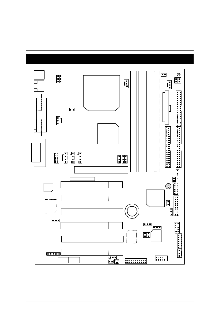
6OXM7 系列主機板
6OXM7 系列主機板的元件配置圖
PS/2
USB
JP1 JP3
PGA 370
CPU
J1
JP4
LED1
J2
JP7
JP6
JP22
JP9
PCI1
PCI2
PCI3
PCI4
PCI5
PCI6
AMR
JP5
Floppy
ATX Power
FW82815
IDE2
J5
J7
J6
AGP
DFP/TV
JP10
JP11
JP25
DIMM1
DIMM2
DIMM3
DIMM4
ICH82801
IDE1
J10
JP12
BZ1
JP13
JP14
6OXM7
JP23
J12
J13
BAT1
Backup
BIOS
J15
JP18
JP20
JP15
J11
JP19
CN9
Main
BIOS
JP21
COM B
CN12
J14
COM A
LPT
VGA
CN7
Game & Audio
AC’97
Creative
CT5880
JP16
JP24
5
Page 17

6OXM7 系列主機板的元件配置圖
$ CPU 速度設定 / 插座及接腳設定的快速安裝指南 頁數
CPU 速度設定 P.8
插座 P.9
遊戲搖桿及音源插座 P.9
COM A串列插座 / COM B串列插座 / 螢幕接頭 / LPT 並列插座 P.9
CN2 (USB規格插座)[Back] P.10
PS/2鍵盤及PS/2滑鼠插座 P.10
J1 (CPU散熱風扇電源接腳) P.11
電源散熱風扇電源接腳
J2 (
)
P.11
J14 (系統散熱風扇電源接腳) P.12
ATX 電源插座 P.12
JP13 (IR/CIR ) [紅外線連接端/商業用紅外線接腳] P.13
Floppy (軟碟插座) P.13
第一組IDE 1插座 / 第二組IDE 2插座 P.14
J13 (Ring Power On) (內建數據機喚醒功能接腳) P.14
J12 (Wake On LAN) (網路喚醒功能接腳) P.15
J7 (TEL) (數據機內部發聲接腳) P.15
J6 (AUX_IN 接腳) P.16
J5 (光碟機音源線接腳) P.16
JP9 (SPDIF 接腳) [選購] P.17
JP7 (STR指示燈接腳& LED1: DIMM 指示燈) [選購] P.17
CN9 (USB規格插座)(Front) [選購] P.18
J10 (外部SMBUS設備接腳) P.18
CN7 (音源接腳 ) [Front] [選購] P.19
CN8 (數位平面顯示器/電視輸出插座) [DFP/TV Out ] P.19
J15 (IA 控制面板插座) [選購] P.20
CN12 (讀卡機連接頭) [SCR] P.20
接腳定義說明 P.21
J11 (2x11 Pins接腳)說明 P.21
JP18 (清除CMOS功能接腳) P.22
JP4 (STR功能選擇接腳) [選購] P.22
JP16 (內建音效卡功能選擇接腳) [選購] P.23
JP3 (PS/2鍵盤開機功能接腳) P.23
JP1 (後面板USB設備喚醒功能選擇接腳) P.24
JP22 (主機外殼開啟顯示接腳) P.24
JP20 (BIOS寫入保護) P.25
6
Page 18
6OXM7 系列主機板
JP21 (Top Block Lock接腳) P.25
JP5 (CPU電壓選擇) P.26
JP6 (DIMM電壓選擇) [選購] P.26
JP12 (內建蜂鳴器開關接腳) [選購] P.27
JP14 (自動重新開機功能接腳) P.27
JP15 (系統啟動方式選擇接腳) P.28
JP19 (前面板USB設備喚醒功能選擇接腳) [選購] P.28
JP23 (PCI/AGP 3VAUX) P.29
JP24 (AMR 選擇接腳) [選購] P.29
7
Page 19
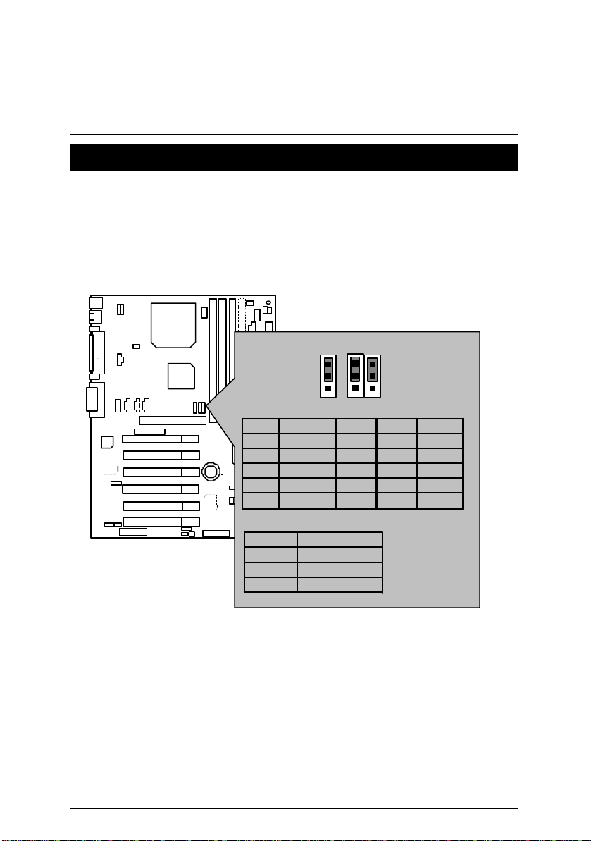
CPU 速度設定
CPU速度設定
您可以利用JP10/JP11 及JP25(見圖1)來做系統外頻切換, 選擇 100MHz 及 133MHz
或Auto. CPU倍頻由 BIOS自動去偵測控制.
M
請注意主機板上設定的倍頻及外頻,需要和CPU的倍頻及外頻相符合,否則易
造成系統當機。
JP10/JP11/JP25: CPU速度設定 (選購)
1
1
1
JP25
JP11
JP10
CPU SDRAM JP25 JP10 JP11
Auto Auto 1-2 1-2 1-2
66 100 1-2 2-3 2-3
100 100 1-2 2-3 Open
133 133 1-2 Open 2-3
133 100 2-3 Open Open
自動組態設定:
CPU SDRAM
66 100
100 100
133
Ö
133/100
圖 1
Ö 若您的 CPU 外頻為133 MHz, BIOS 會自動偵測 SDRAM的 SPD值, 判斷Memory 的
最佳執行頻率.
M 若您的主機板上無JP10,JP11及JP25接腳, 系統外頻將由BIOS自動偵測. 若是此3
個接腳有效存在, 您可作 66MHz, 100MHz, 133MHz 或 Auto 的頻率選擇.
M請依據您CPU的規格來設定CPU 的頻率,我們不建議您將系統速度設定超過硬
體之標準範圍,因為這些規格對於周邊設備而言並不算是符合標準規格。 如果您
要將系統速度設定超出標準規格 , 請依據您的硬體規格設定, 例如;CPU,顯示卡,
記憶體,硬碟來設定.
8
Page 20
6OXM7 系列主機板
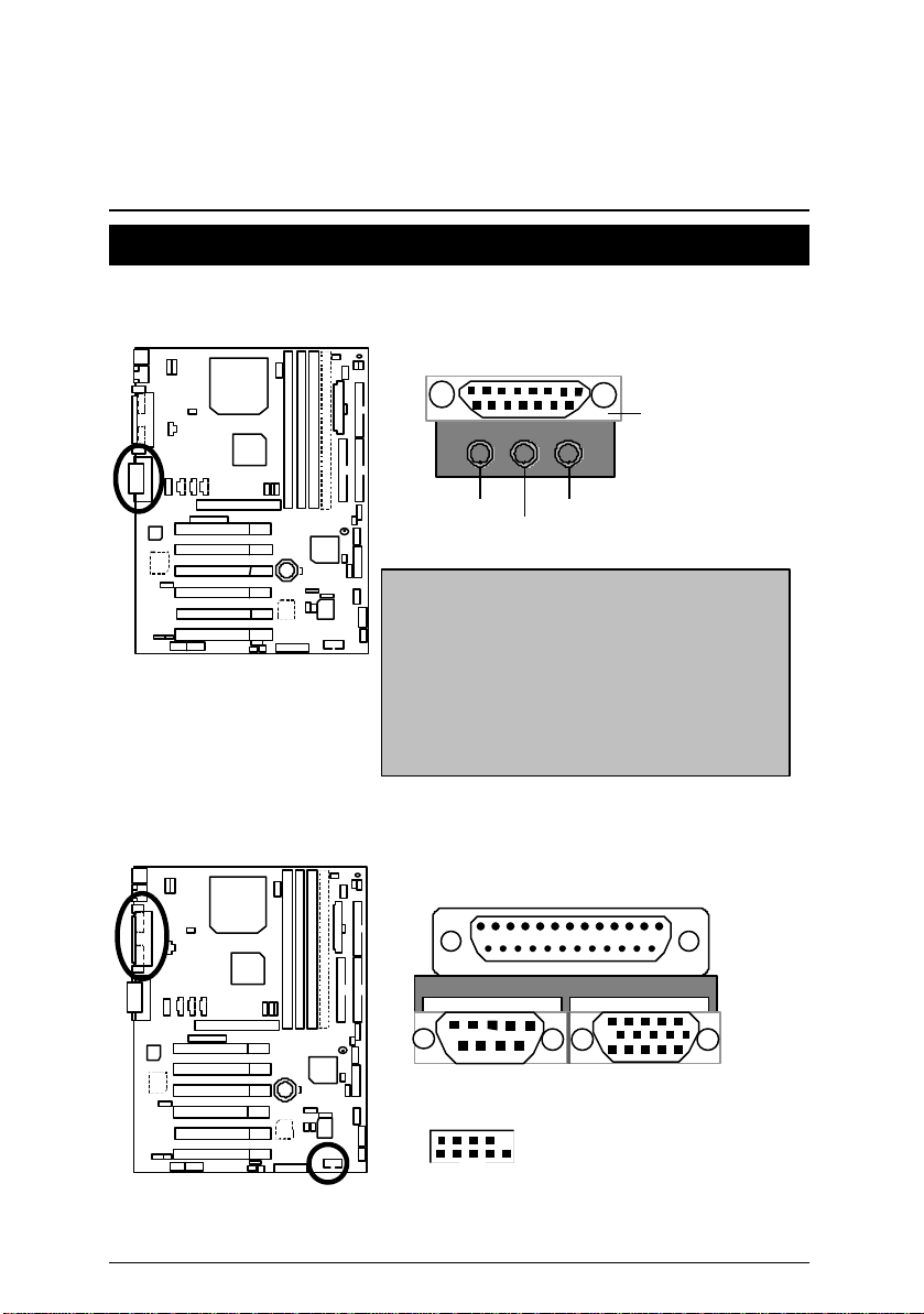
插座
遊戲搖桿及音源插座
Game
Port
Line Out 1
MIC In
Line In
Line Out 1: Line Out 或 SPDIF (
到喇叭或供給
是”Line Out”, 當輸出是數位訊號,將會自動切換
到
”SPDIF Out” (
一般說來正常模式是
Line In:
Creative
訊請參考 45頁) ”Line In” 會變成”Line Out 2”, 接著
你便能在
喇叭
應用程式中選擇
Line Out 1及Line In
.
杜比解碼器
AC3
其他資訊請參考47頁
提供數位音效輸出
一般說來正常模式
).
).
”Line In”.
“Four Speaker” , (
當您在
同時插入二組立體聲
其他資
COM A串列插座/ COM B串列插座/ 螢幕接頭 / LPT並列插座
LPT Port
COM A
2
10
COM B
9 1
VGA
9
Page 21
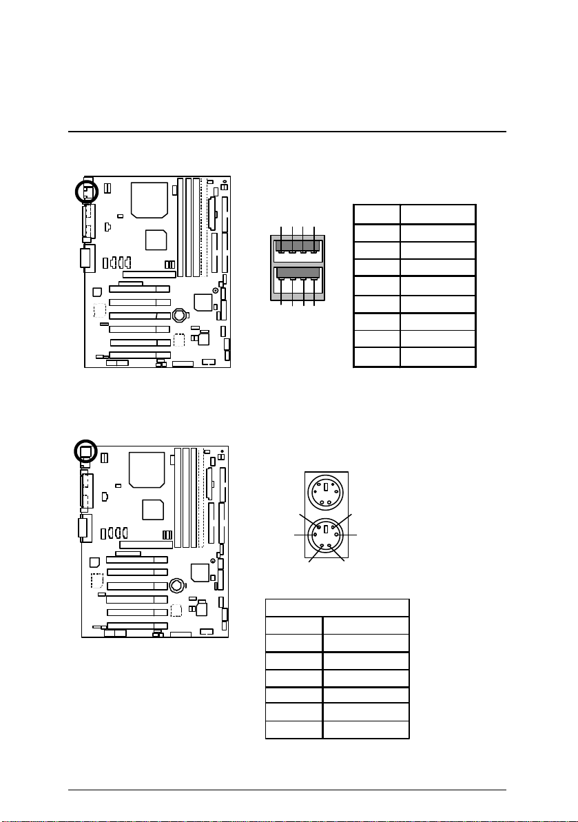
CN2: USB規格插座(Back)
1
插座及接腳設定的快速安裝指南
PS/2鍵盤及 PS/2滑鼠插座
接腳 定義
滑鼠
5
3
1 2
2
3
PS/2
6
4
8 7 6 5
4
PS/2 鍵盤
滑鼠/鍵盤
PS/2
接腳
1
2
3
4 VCC(+5V)
5
6
定義
資料訊號線
無作用
接地線
時脈
無作用
1 USB V0
2 USB D03 USB D0+
4 接地線
5 USB V1
6 USB D17 USB D1+
8 接地線
10
Page 22
6OXM7 系列主機板
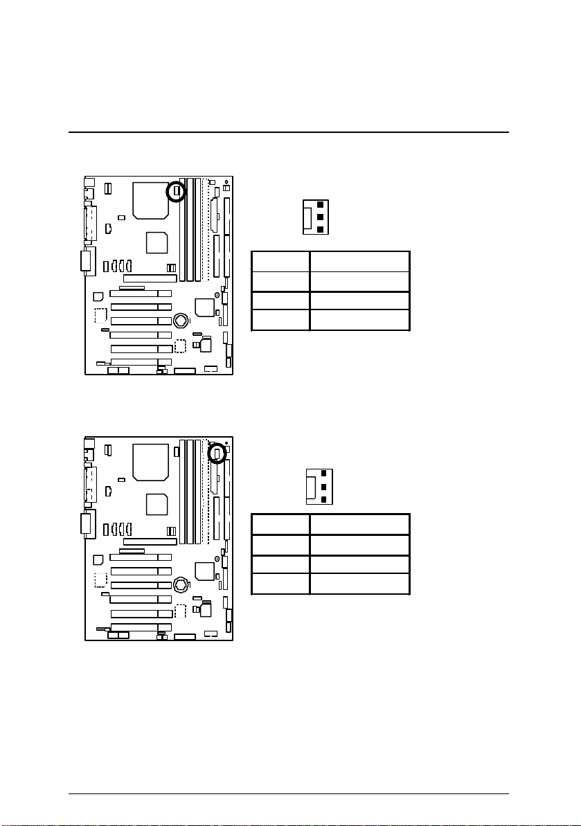
J1: CPU 散熱風扇電源接腳
J2: 電源散熱風扇電源接腳
1
接腳 定義
1
風扇運轉控制
2 +12V
3 偵測訊號線
1
接腳 定義
1 風扇運轉控制
2 +12V
3
偵測訊號線
11
Page 23
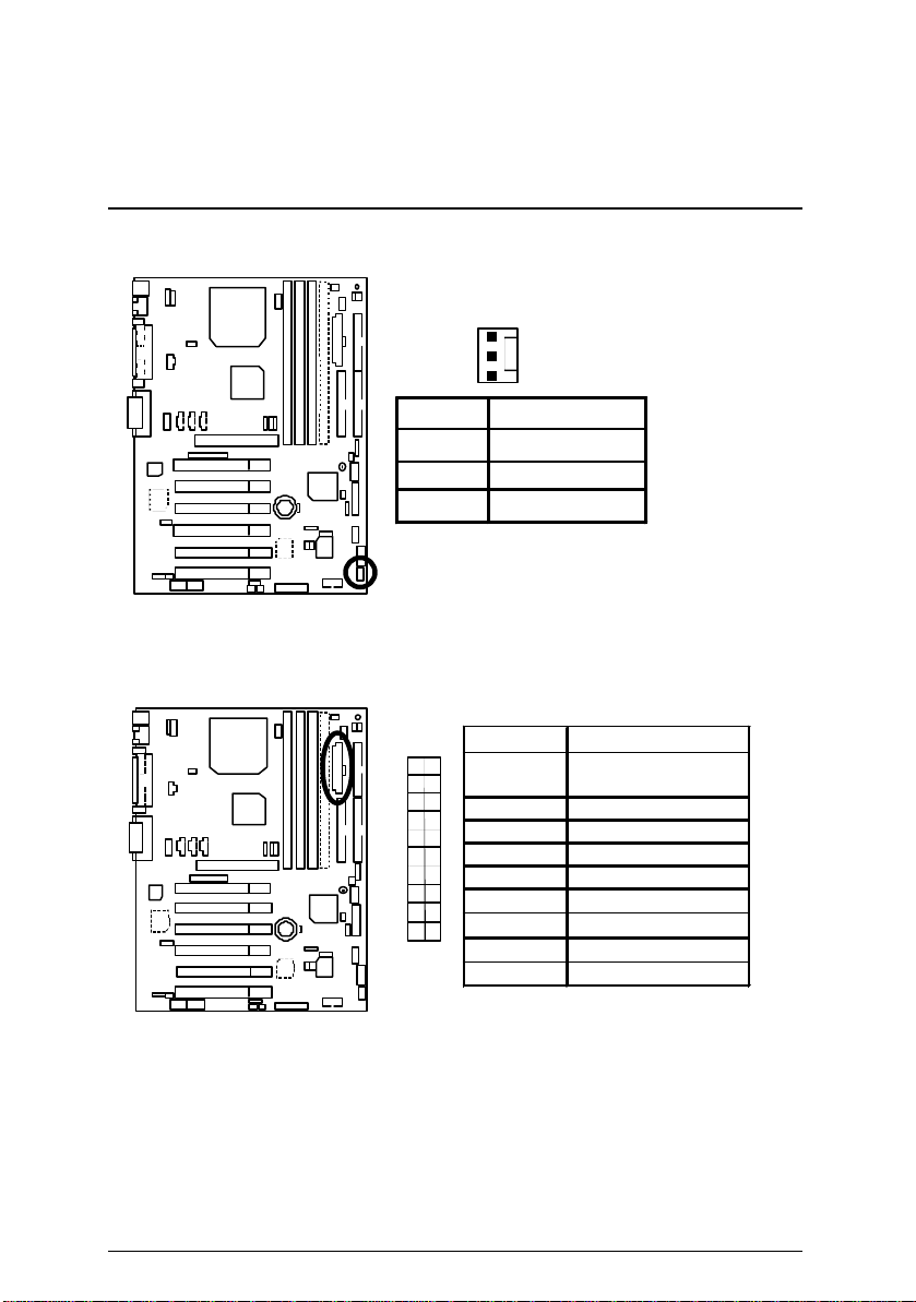
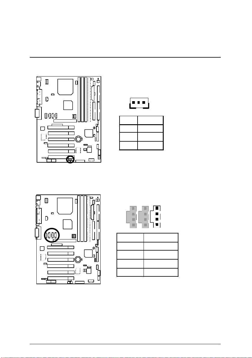
J14: 系統散熱風扇電源接腳
插座及接腳設定的快速安裝指南
1
接腳 定義
1 風扇運轉控制
2 +12V
3 偵測訊號線
ATX 電源插座
接腳
10
20
3,5,7,13,
15-17
定義
接地線
1,2,11 3.3V
4,6,19,20 VCC
10 +12V
12 -12V
18 -5V
11
1
8 電源良好訊號
9 5V SB stand by+5V
14 PS-ON(Soft On/Off)
12
Page 24
6OXM7 系列主機板
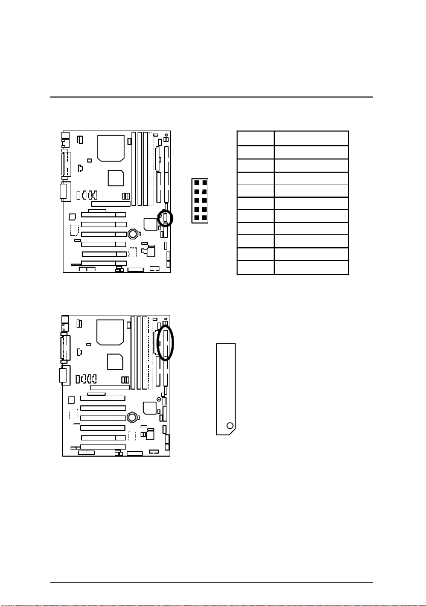
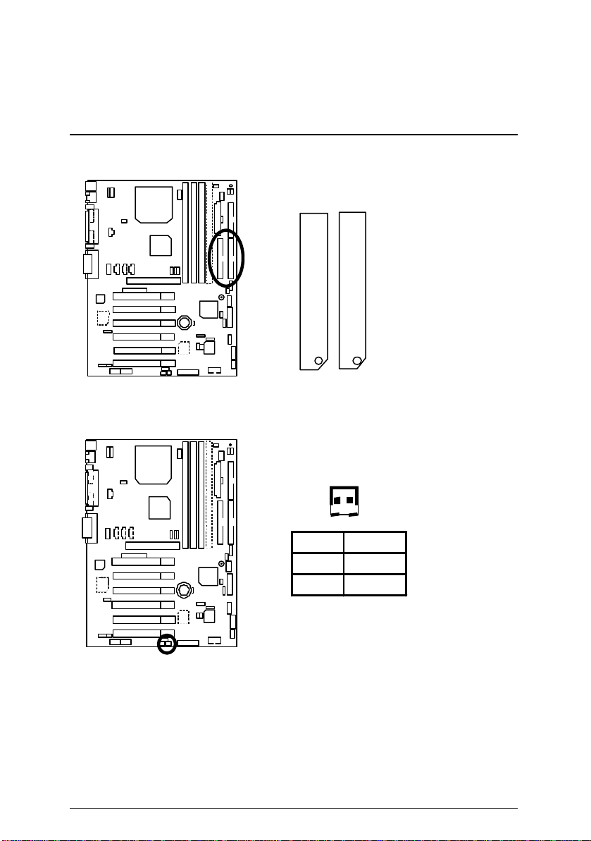
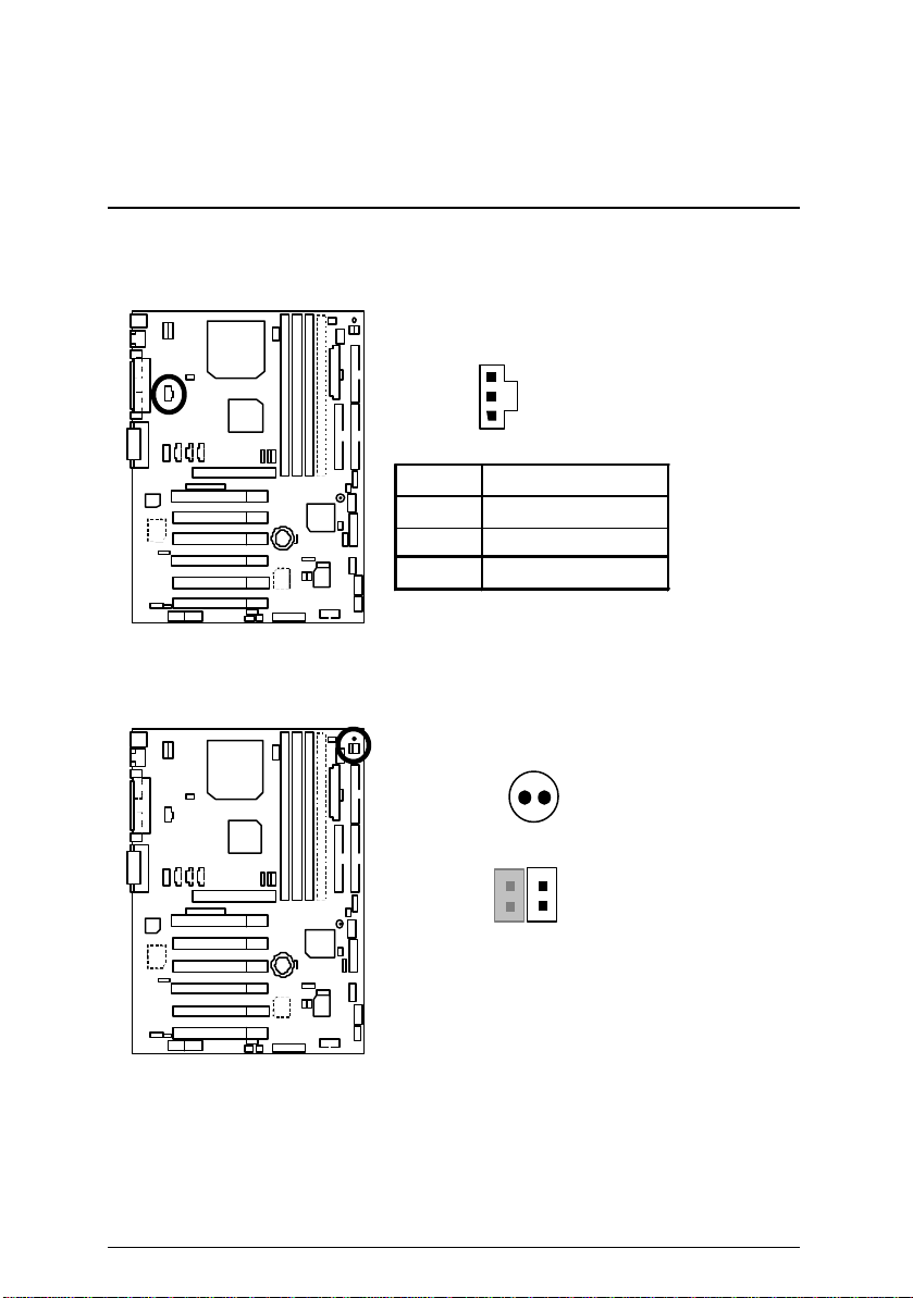
JP13: IR/CIR(紅外線連接端/商業用紅外線接腳
1
5 6 10
接腳
1
2
3 IRRX
4
5 IRTX
6
7 CIRRX
8
9
10
Floppy: 軟碟插座
)
定義
電源線
無作用
接地線
無作用
電源線
無作用
無作用
紅色線
13
Page 25
插座及接腳設定的快速安裝指南
第一組 IDE 1插座 / 第二組 IDE 2插座
IDE 2 IDE 1
紅色線
J13: Ring Power On (內建數據機喚醒功能接腳)
1
接腳 定義
訊號線
1
接地線
2
14
Page 26
6OXM7 系列主機板
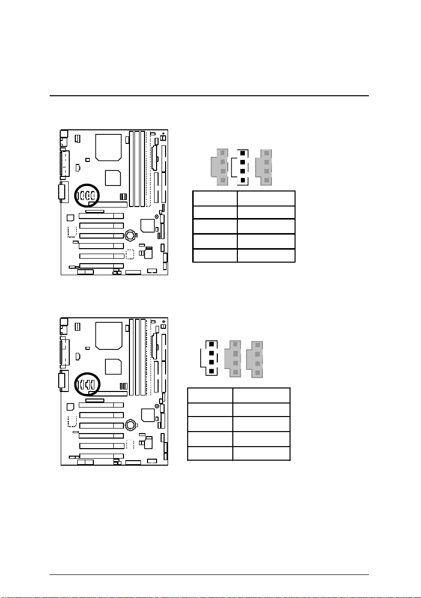
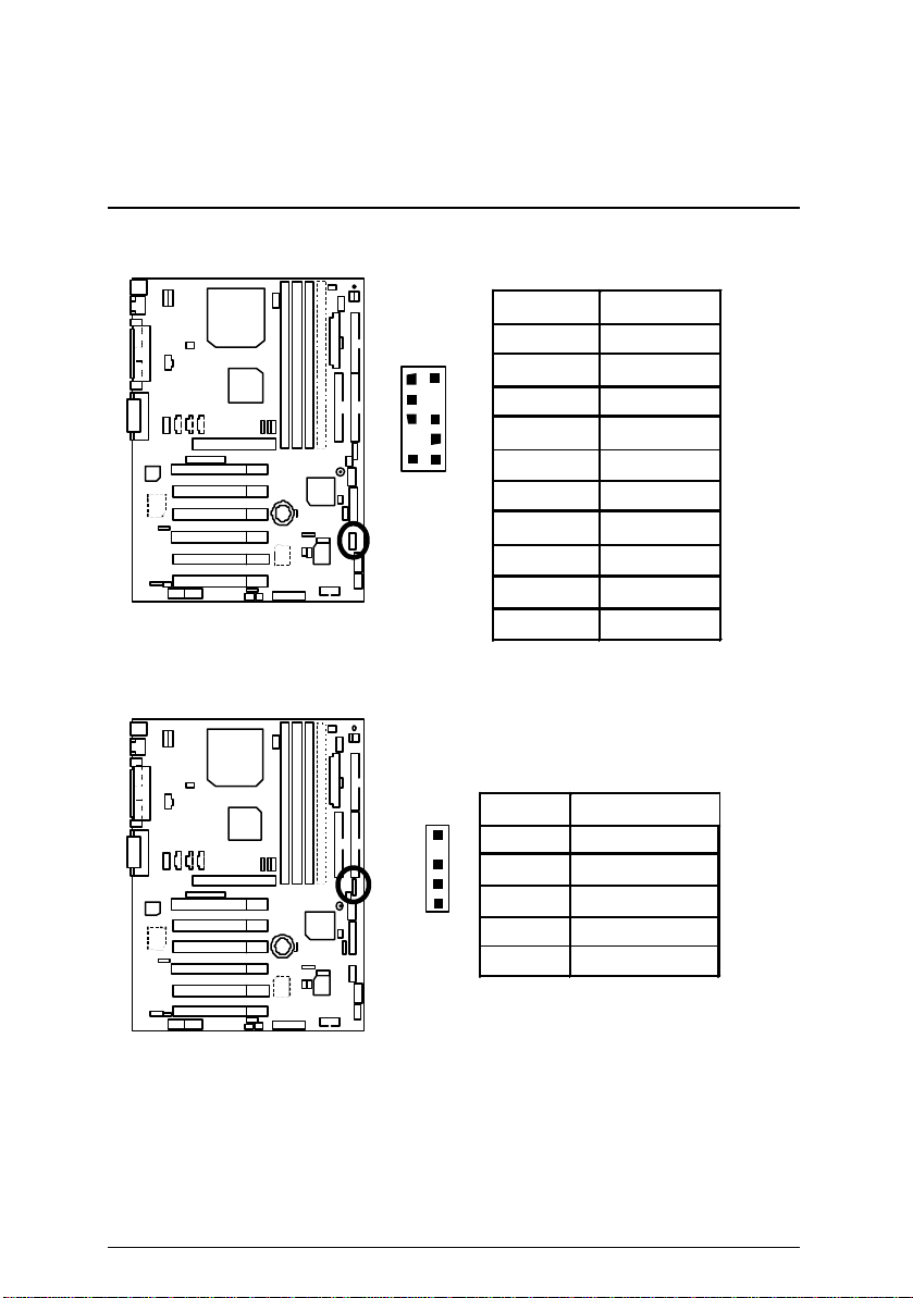
J12: Wake On LAN (網路喚醒功能接腳)
1
接腳 定義
1 +5V SB
2 接地線
3 訊號線
J7: TEL: 數據機內部發聲接腳
1
接腳 定義
1 Signal-In
2 接地線
3 接地線
4 Signal-Out
15
Page 27
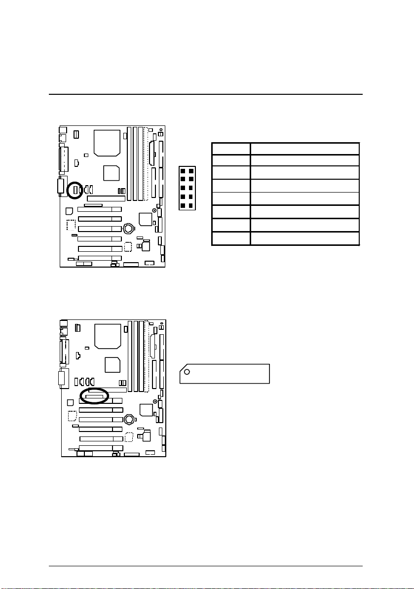
J6: AUX_IN 接腳
接腳 定義
1 AUX-L
2
3 接地線
4 AUX-R
J5: CD Audio Line In (光碟機音源線接腳)
1
插座及接腳設定的快速安裝指南
1
接地線
接腳 定義
1 CD-L
2 接地線
3 接地線
4 CD-R
16
Page 28
6OXM7 系列主機板
+
JP9: SPDIF 接腳(提供數位音效輸出到喇叭或供給AC3杜比解碼
器)(選購)
1
接腳 定義
1 電源
2 SPDIF OUT
3 接地線
JP7: STR 指示燈接腳及 LED1 : DIMM 指示燈(選購)
DIMM 指示燈
1
指示燈外部接腳
STR
17
Page 29
CN9: USB規格插座(Front) (選購)
1
9
J10: 外部SMBUS設備接腳
2
10
插座及接腳設定的快速安裝指南
接腳
定義
1 +5V
2 接地線
3 USB D24 無作用
5 USB D2+
6 USB D3+
7
無作用
8 USB D39 接地線
10 +5V
接腳
1
1 SMB CLK
定義
2 無作用
3 接地線
4 SMB DATA
5 +5V
18
Page 30
6OXM7 系列主機板
CN7: 音源接腳 (Front) (選購)
接腳 定義
1 Line-out (R)
1
9
2
10
2 Line-out (L)
3, 4
5 Line-in/2nd Line-out (R)
6 Line-in (L)/2nd Line -out (L)
7, 8, 10 接地線
9 Mic-in
接地線
CN8: 數位平面顯示器/電視輸出插座(DFP/TV Out)
í僅支援技嘉 Digital Flat Panel/TV -Out 子卡 (GA-DFP-x).
1
2
27
28
19
Page 31

J15: IA 控制面板插座(選購)
2
插座及接腳設定的快速安裝指南
20
CN12: SCR: 讀卡機連接頭
1
13
1
接腳 定義
1 Giga-byte web-site
2 Internet
3 Finance
4 Entertainment
5 Shopping
6 Searching
7 People
8 E-mail
9 Play-pause
10 Forward
11 Rewind
12 Eject
13 Stop
14 Mute
15 Mic Volume up
16 Mic Volume down
17 Speaker Volume up
18 Speaker Volume down
19
20
19
接地線
無作用
接腳 定義
2
1 VCC
2,3,4,8,13 無作用
5,6,10,12 DATA
7 Clock
14
9,14 無作用
11 接地線
20
Page 32

6OXM7 系列主機板
RE
接腳定義說明
J11: For 2x11 Pins 接腳說明
GN
HD
1
1
GN : 省電模式開關
(Green Switch)
GD : 省電模式指示燈
(Green LED)
HD : 硬碟存取指示燈接頭
(IDE Hard Disk Active LED)
SPK : 內建蜂鳴器
(Speaker Connector)
RE : 重置開關接頭
(Reset Switch)
P+P−P− : 電源指示燈
(Power LED)
PW : 按鍵開/關機
(Soft Power Connector)
1
S P K
1
PW P+ P− P−
1
GD
開路: 一般運作
短路: 進入省電模式
接腳 1: LED 燈號正極(+)
接腳 2: LED 燈號負極(−)
接腳 1: LED 燈號正極(+)
接腳 2: LED 燈號負極(−)
接腳 1: 電源線VCC(+)
接腳 2- 接腳 3: 無作用
接腳 4: 資料輸出線(−)
開路: 一般運作
短路: 強迫系統重新開機
接腳 1: LED 燈號正極(+)
接腳 2: LED 燈號負極(−)
接腳 3: LED 燈號負極(−)
開路: 一般運作
短路: 啟動電源開關
21
Page 33

插座及接腳設定的快速安裝指南
22
Page 34

6OXM7 系列主機板
JP18: 清除CMOS功能接腳
1 -2 短路 清除 CMOS
2 -3 短路 一般運作(預設值)
JP4: STR 功能選擇接腳 (選購)
1
接腳 定義
1
接腳 定義
短路 啟動 STR
開路 關閉
STR
(預設值)
23
Page 35

JP16: 內建音效卡功能選擇接腳 (選購)
插座及接腳設定的快速安裝指南
1
JP3: PS/2 鍵盤開機功能接腳
1-2 短路 啟動PS/2 鍵盤開機
2-3 短路 一般運作 (預設值 )
接腳
短路 開啟內建音效卡功能
1-2
(預設值)
短路 關閉內建音效卡功能
2-3
1
接腳 定義
功能
定義
24
Page 36

6OXM7 系列主機板
JP1: 後面板USB設備喚醒功能選擇接腳 (USB Port à CN2)
1
接腳 定義
1-2 短路 啟動後面板 USB 設備喚醒
功能
2-3 短路 一般運作(預設值)
CN2
JP22: 主機外殼開啟顯示接腳
若您要使用
(
須在
設定為啟動,並將
開機後當記憶體開始偵測計算時,按下
*(
入
BIOS
SETUP"
Enabled".
SETUP" 將變更的設定儲存並離開)
"USB KB/Mouse Wake from S3"
選項內將
BIOS
Jumper "JP1及JP4 "
內選項設定,在
內,選擇
"USB KB/Mouse Wake from S3:
按下
"ESC"
"USB KB/Mouse Wake from S3"
”POWER MANAGEMENT
鍵回到
"SAVE & EXIT
1
接腳
定義
1 訊號線
接地線
2
功能,
也設為啟動
您將可進
<Del>
.
您必
).
25
Page 37

JP20: BIOS寫入保護
M
BIOS
Jumper
JP21: Top Block Lock接腳
插座及接腳設定的快速安裝指南
1
接腳 定義
短路 寫入保護
開路 一般運作(預設值
當您要更新
JP20 設為”開路”, 關閉 BIOS 防寫功能.
或設備時,請將
)
1
接腳 定義
開路 Top Block Lock
短路 Top Block Unlock (預設值)
26
Page 38

6OXM7 系列主機板
27
Page 39

JP5: CPU電壓選擇 (Magic Booster)
(當JP5設為” 短路” 時,CPU Voltage 會提高10%)
1
接腳 定義
短路 Turbo
[提高電壓 10%]
開路 一般運作(預設值)
JP6: DIMM 電壓選擇(選購)
1
插座及接腳設定的快速安裝指南
接腳 定義
短路 啟動 DIMM 電壓選擇功能
開路 關閉 DIMM 電壓選擇功能
(預設值)
28
Page 40

6OXM7 系列主機板
JP12: 內建蜂鳴器開關接腳(選購)
接腳 定義
開路 關閉內建蜂鳴器
短路 啟動內建蜂鳴器
JP14: 自動重新開機功能接腳
1
(預設值)
1
接腳 定義
開路 啟動自動重新開機功能
短路 關閉自動重新開機功能
29
Page 41

插座及接腳設定的快速安裝指南
30
Page 42

6OXM7 系列主機板
JP15: Safe mode / Recovery / Normal系統啟動方式選擇接腳
1
接腳 定義
1-2 短路 一般運作(預設值)
2-3 短路 安全模式
1-2-3 開路 BIOS 重建
JP19: 前面板USB設備喚醒功能選擇接腳 (選購)
(USB Port à CN9)
1
CN9
接腳 定義
1-2 短路 啟動前面板 USB 設備喚
醒功能
2-3 短路 一般運作(預設值)
若您要使用
(
您必須在
from S3"
設為啟動
開機後當記憶體開始偵測計算時,按下
*(
可進入
MANAGEMENT SETUP"
Wake from S3: Enabled".
"SAVE & EXIT SETUP"
"USB KB/Mouse Wake from S3"
選項內將
BIOS
設定為啟動,並將
).
內選項設定,在
BIOS
31
"USB KB/Mouse Wake
Jumper "JP19及JP4 "
”POWER
內,選擇
"USB KB/Mouse
按下
"ESC "
將變更的設定儲存並離開
<Del>
鍵回到
功能,
.
您將
也
)
Page 43

JP23: PCI/AGP 3VAUX
Suspend
PME
M
提供系統在
JP24: AMR 選擇接腳 (選購)
插座及接腳設定的快速安裝指南
1
接腳 定義
開路 關閉 PCI/AGP 3VAUX
短路 啟動 PCI/AGP 3VAUX
(預設值)
3 VAUX 為PCI/AGP的3V Standby 電流,
模式下,啟動
的應用
1
1-2
接腳
短路
AMR Secondary
定義
AMR Primary
關閉
短路
2-3
32
AC’97 (
關閉內建
(
預設值
CODEC)
)
Page 44

效能測試
效能測試
以下是 6OXM7的測試數據,基本上這些測試數值僅供參考,因為不同的軟、硬體
配備都會影響測試結果,所以我們無法保證使用者自行測試的數據會與下列公佈
數值完全吻合。
• CPU Intel Socket 370 處理器
• 記憶體 (128 x 2) MB SDRAM (Buffalo KM48S8030CT-GA)
• 快取記憶體
CPU內建256 KB快取記憶體(Pentium® !!!)
CPU內建128 KB快取記憶體(CeleronTM)
• 顯示介面卡 內建顯示晶片
• 儲存裝置 內建 IDE 插座(Quantum KA13600AT)(13.6G)
• 作業系統 Windows NT™ 4.0 (SP6a)
• 驅動程式 顯示卡驅動程式使用 1024 x 768 x 16M x 75Hz 解析度
Intel Pentium® !!!
Socket 370
Processor
Winbench99
CPU mark99 75.8 69.1 41.5 29
FPU Winmark 99 4610 4520 3190 1880
Business Disk Winmark 99 5480 5140 4840 4490
Hi-End Disk Winmark 99 12900 12500 12100 12300
Business Graphics Winmark 99 133 113 98.4 91.7
Hi-End Graphics Winmark 99 607 552 381 266
866MHz
(133x6.5
)
850MHz
(100x8.5)
Intel Celeron
Socket 370
600MHz
(66x9)
TM
350MHz
(100x3.5)
Winstone99
Business Winstone99 40.2 37.2 29.3 25.3
Hi-End Winstone99 48.8 45 32.8 25.6
33
Page 45

插座及接腳設定的快速安裝指南
M 如果您想使您的系統獲得最高效能,詳細資料請參考第64頁。
34
Page 46

6OXM7 系列主機板
82801AA
晶片組功能方塊圖
Socket 370
66/100/133 MHz
AGP 2X/4X
/Display Cache
ATA66 IDE Channels
2 USB Ports
COM Ports
LPT Port
Display
DFP/TV
81181
PS/2
W
IT8712
2 USB Ports
IR Floppy
Host Bus 66/100/133MHz
Intel
FW82815
Hub
Interface
ICH
FWH
Game Port
Smart Card Reader
3.3V SDRAM
100/133 MHz
14.318/33/48/66 MHz
PCI Bus 33MHz
AC’97 Link
CT5880
AC’97
66/100/133 MHz
ICS
9250-25
6 PCI
31
Page 47

安裝Suspend to RAM功能
安裝Suspend To RAM 功能(選購)
A.1 STR 功能簡介
STR是一種Windows 98 ACPI下的暫停模式功能。 當恢復STR暫停模式,系統能夠在
幾秒鐘之內回復到進STR(S3)之前的狀態, 這狀態是在系統進入暫停模式之前就已
經被存在記憶體內,當在STR暫停模式時,系統將會使用少量的能源去維持STR功
能重要的資料,並支援各種不同模式的喚醒功能。
A.2 STR 功能安裝
請依照下列步驟來完成STR安裝
步驟1:
要使用STR功能, 系統必須在Windows 98 ACPI 模式:
使用Windows 98光碟片安裝
A. 將Windows 98光碟片放入光碟機中, 選擇開始, 並執行。
B. 依Window規定鍵入 “D:\Setup”, 按下 enter或雙擊滑鼠兩下。
C. 當安裝完成後,從光碟機中移除光碟片, 並重新啟動您的系統。
(我們假設光碟機的代號為D:)
32
Page 48

6OXM7 系列主機板
步驟 2:
當使用
功能之前,您需要設定主機板上的
STR
JP4短路,
如下圖所示
:
1
接腳 定義
短路 啟動 STR
開路 關閉
STR
(預設值)
步驟 3:
當系統開機開始計算記憶體時, 按下<Del>。您將會進入BIOS設定畫面,選
擇” POWER MANAGEMENT SETUP”,並選” ACPI Suspend Type: S 3(Suspend to
RAM)” 。請務必記得要按下”ESC”並選擇” SAVE & EXIT SETUP” 來儲存設定。
恭喜您!!您已經順利的完成了STR的功能安裝。
33
Page 49

A.3 如何讓您的系統進入STR模式?
有兩種方式來完成:
1.選擇” 關閉Windows” 中的” 暫停” 選項
A. 在Windows98功能列選擇” 開始” 並選” 關機”
B. 選擇” 暫停” 並按下” 確定” 。
安裝Suspend to RAM功能
34
Page 50

6OXM7 系列主機板
2. 定義系統開機時是在STR模式中:
A. 用滑鼠雙擊” 我的電腦” 中的” 控制台” 。
B. 用滑鼠雙擊” 電源管理” 選項。
35
Page 51

安裝Suspend to RAM功能
C. 選擇” 進階” 並選” 等候使用” 模式.
D. 在完成設定後重新啟動你的系統.當您想要進入STR省電模式時, 只要按
下” 電源開關” 按鈕即可。
A.4 如何恢復到STR省電模式?
有7種方式可” 喚醒” 系統:
1. 按下” 電源開關” 按鈕。
2. 使用”PS/2 鍵盤開機” 功能。
3. 使用” 滑鼠開機” 功能。
4. 使用” 定時開機” 功能。
5. 使用” 數據機開機” 功能。
6. 使用” 網路卡開機” 功能。
7. 使用”USB裝置喚醒” 功能。
36
Page 52

6OXM7 系列主機板
+
A.5 注意事項:
1.為了要使用正確的STR功能,一些硬體及軟體的需求是必須符合的:
A. 您的ATX 電源供應器必須要是ATX 2.01的規格(供應超過720毫安培5V
Stand-By 電流)
B. SDRAM 必須是符合PC-100規格.
2. JP7 是STR指示燈的連接頭.當系統進入STR省電模式時, STR指示燈將會亮起.
DIMM 指示燈
1
指示燈外部接腳
STR
37
Page 53

雙 BIOS 功能介紹
Press DEL to enter SETUP
雙BIOS(Dual BIOS)功能介紹 (選購)
A. 何謂雙BIOS (Dual BIOS)?
主機板上有兩顆BIOS,分別為” 主要BIOS(Main BIOS)”及” 備份BIOS (Backup
BIOS)”。在一般的正常狀態下,系統是由主要BIOS在運作,若您的系統主要BIOS
損壞時,則備份BIOS將會接管開機的動作並自動修復主要BIOS,此時您的系統
就可以像以往一樣正常的工作。
B. 雙BIOS功能及使用方法
a. 開機畫面
Award Modular BIOS v6.00PG, An Energy Star Ally
Copyright (C) 1984-2000, Award Software, Inc.
Intel XXXX AGPSet BIOS for XXXX
Check System Health ok , Vcore =1.65V
Main Processor : PENTIUM III 866MHz (133x6.5)
<CPU ID:0683 , Patch ID:0010>
Memory Test :262144K OK
Press F1 to enter Dual BIOS Utility, ESC to quit
按下 “F1” 進入Dual BIOS程式畫面
38
Page 54

6OXM7 系列主機板
b. Dual BIOS 程式畫面
Dual BIOS Utility V6.60.g.01K
(C) 1999, Gigabyte Technology Co., LTD.
Wide Range Protection :Disabled
Halt On BIOS Defects :Disabled
Auto Recovery :Enabled
Boot From :Main BIOS
BIOS Recovery :Main to Backup
F3: Load Default F5:Start BIOS Recovery
F7: Save And Restart F9:Exit Without Saving
Use <Space> key to toggle setup
C. Dual BIOS 程式選項說明
Wide Range Protection: Disabled(預設值), Enabled
狀況1:
當主要BIOS在電源開啟之後,作業系統載入前,若有Failure狀況(例如:Update
ESCD Failure, Checksum Error或Reset), 此時Wide Range Protection若設為
Enabled,會自動切換到備份BIOS來完成開機動作。
狀況2:
周邊卡(例如:SCSI卡,網路卡…) 上若有ROM BIOS,並進其BIOS內做任何的設
定, 設定完畢後,此時若由周邊卡的ROM BIOS發出訊號要求系統重開機,則
不會由備份BIOS來開機。
但若是使用者自行按電腦機殼面版重開機按鈕,則會由備份BIOS來開機。
Halt On BIOS Defects : Disabled(預設值), Enabled
當Halt On BIOS Defects 設為Enabled時,若CHECKSUM ERROR或MAIN BIOS IS
WIDE RANGE PROTECTION ERROR, 則開機時會出現以下訊息;並使系統暫
停,等待使用者按鍵做進一步處理:
若 Auto Recovery :Disabled會顯示<or the other key to continue.>
若 Auto Recovery :Enabled會顯示<or the other key to Auto Recover.>
39
Page 55

雙 BIOS 功能介紹
Auto Recovery : Enabled(預設值) , Disabled
主要BIOS或備份BIOS其中一顆Checksum F ailure時, 正常的BIOS會自動修復
Checksum Failure的BIOS。
{在BIOS 設定中的Power Management Setup內, ACPI Suspend Type選項若選
Suspend to RAM,此時Auto Recovery會自動設定為Enabled。}
Boot From : Main BIOS (預設值) , Backup BIOS
狀況1:
使用者可自行設定開機要由主要BIOS或是備份BIOS來開機。
狀況2:
主要BIOS或備份BIOS其中一顆BIOS損壞,此項設定會變灰,使用者也無法更改
設定。
BIOS Recovery : Main to Backup
自動修復動作提示:
BIOS Recovery :Main to Backup
表示Main BIOS能正常開機並會自動修復Backup BIOS
BIOS Recovery :Backup to Main
表示Backup BIOS能正常開機並會自動修復Main BIOS
此修復程式為系統自動設定,使用者無法變更。
D. 功能鍵說明
F3:Load Default (載入預設值)
F5:Start BIOS Recovery (開始BIOS自動修復)
F7:Save And Restart (儲存設定並重開機)
F9:Exit Without Saving (離開Dual BIOS程式並且不儲存設定)
Use <Space> Key to toggle setup (請使用空間棒來更改設定)
40
Page 56

6OXM7 系列主機板
DualBIOS
TM
技術問答集
主板的新革命
首創雙 BIOS主板新紀元
您的主板 BIOS是否曾經因昇級失敗或中毒,而導致整台電腦故障,送修後
又得忍受沒有電腦可用的煎熬?
技嘉科技獨創全球第一片 DualBIOSTM (主板內建雙 BIOS)的新技術,讓您免
除上述的煩惱。這項新技術在第一顆 BIOS的資料遺失或損毀時,會自動啟
用第二顆 BIOS繼續完成開機的動作,並可以修復第一顆 BIOS。
手機用雙頻、車子開雙 B不稀奇,使用技嘉科技 DualBIOSTM (雙 BIOS)主板
才是最高檔的選擇!
在此技嘉科技為您隆重介紹DualBIOS
TM
(雙BIOS)技術,它是一個在系統內隨
時可被使用的BIOS。技嘉科技特別為您提供了這項物超所值的功能,並在未
來將會在技嘉科技的所有主機板上提供此功能。
41
Page 57

雙 BIOS 功能介紹
問答集
問 I.什麼是 DualBIOS
TM
科技?
答:
DualBIOS
TM
是由技嘉科技已申請專利的一項技術, 主機板上有兩顆BIOS, 分
別為” 主要BIOS(Main BIOS)” 及” 備份BIOS (Backup BIOS)” 。
若您的主要BIOS損毀,備份BIOS將會自動取代主要的BIOS並在下次啟動電腦
時將會接管開機的動作並自動修復主要BIOS。這個動作可說是全自動的並
不會有任何遲緩,不管問題是由於燒錄 BIOS時失敗或中毒或其他原因導致您
的主要BIOS故障,備份BIOS將會全自動為您處理。
問II. 為什麼主機板上需要DualBIOS
答:
TM ?
在今天電腦系統愈來愈多的問題是由於BIOS故障而引起電腦不開機,一般最
常見是中毒,或BIOS升級時失敗,及BIOS本身晶片損毀..等問題。
1.現已發現愈來愈多的病毒會攻擊並損壞您的系統BIOS,它們會導致您 的系
統不穩或甚至不開機的情況發生。
2 BIOS內的資料可能損毀的情況有:系統突然斷電或使用者將系統不正常的
重新開機,或是使用者在升級當中突然斷電。
3.若使用者升級到錯誤的BIOS版本,也可能導致系統無法正常開機或開機後
系統當機。
4.一個BIOS的生命週期根據電子特性原理是有限的。
現在一般的電腦幾乎都是隨插即用的BIOS, 若使用者經常更換周邊裝置配備,
可能也會損毀BIOS,不過這機率較小。
當您使用技嘉科技申請的專利技術,可減少由於上述原因而導致BIOS資料損
毀及系統開機時的當機情形。另外, 此項專利技術也可為您省下一筆因BIOS
而導致的維修經費及時間。
42
Page 58

6OXM7 系列主機板
問 III. DualBIOS
TM
科技如何運作?
答:
1. DualBIOS
TM
科技提供開機期間完整的保護,範圍從POST (Power On Self Test),
ESCD Update,到自動偵測PnP周邊。
2. DualBIOS
TM
科技提供BIOS自動回復的功能,當開機時主要BIOS沒有完成開
機動作或BIOS Checksum錯誤發生時,仍可以正常進入系統。在Dual BIOS程
式中,”Auto Recovery” 的選項將確保主要BIOS或備份BIOS其中一個損壞時,
Dual BIOSTM科技將會自動使用正常的BIOS開機並修復有問題的BIOS。
3. Dual BIOS
TM
提供手動修復的功能,並有一個內建BIOS更新程式,可將系統
內正常BIOS內的資料燒錄到有問題的BIOS內,而不需要執行其他的BIOS燒
錄程式。
4. Dual BIOS
TM
提供單向修復的功能,這項功能將確保有問題的BIOS不會被
誤認為正常的BIOS,而導致正常的BIOS被誤燒錄。
問 IV. 誰需要DualBIOS
TM
科技?
答:
1. 因為現今病毒氾濫,所以每個人的主機板上都應有Dual BIOSTM。目前每
天都有新的,具攻擊性的BIOS病毒產生,而現今一般市面所售出的產品都
無法針對對BIOS有攻擊性病毒有所保護, DualBIOS
TM
科技將提供您的電
腦一個最先進的解決方法:
案例> 兇惡的病毒可能導致您的BIOS損毀,在傳統單顆BIOS主機板上 ,這
部電腦直到維修回來之前都無法使用。
解決方案1> 若”Auto Recovery” 有開啟的話,當電腦中毒時,備份的BIOS將
會自動接管開機的動作並自動修復有問題的BIOS。
解決方案2> 若主要BIOS損毀,使用者也可以進入Dual BIOS程式中,自行選
擇由備份BIOS來開機。
2. 當BIOS完成更新後,若DualBIOSTM偵測到主要BIOS有問題,備份 BIOS將自
動接管開機動作,同時也進行主要BIOS及備份BIOS的 Checksum之確認來
確保BIOS能正常運作。
43
Page 59

雙 BIOS 功能介紹
3. 電腦玩家們可在同一塊主機板上,同時擁有2個不同版本的BIOS,方便玩
家們來調整系統的效能或穩定性。
4. 針對於高階的桌上型電腦及工作站伺服器, Dual BIOSTM也提供了更具彈性
的進階功能。在Dual BIOSTM程式內,若開啟”Halt On When BIOS Defects” 的
選項,則當主要BIOS資料損毀時,系統會暫停並出現警告訊息。但大部份
工作站伺服器都需要不斷工作,在這種情況下, 可關閉 ”Halt On When BIOS
Defects” 選項,以免造成電腦無法進入作業系統。另一個Dual BIOSTM的優
點為:若將來有需要更大的BIOS儲存空間,您可以從2個2Mbit BIOS升級到2
個4Mbit的BIOS。
44
Page 60

6OXM7 系列主機板
Four Speaker 及 SPDIF 功能介紹 (選購)
Four Speaker 功能機介紹
A. 什麼是Four Speaker?
Creative CT5880 音效晶片有支援4 speaker 輸出, 假如您選擇“Four speaker” 輸出,
Line in 將會變成Line out.
B. 如何使用Four Speaker?
a. 按 右下角 Audio 圖示按鈕並選擇 “Configurator 3D Audio”.
b. Two speaker (預設值)
45
Page 61

Four Speaker 及 SPDIF 功能介紹
46
Page 62

6OXM7 系列主機板
c. 按 “Four speaker” 選項.
C. Four Speaker 應用
此four speaker功能只支援Microsoft DirectX 及Creative EAX 等軟體應用.例如:Game
titles, software DVD player及MP3 player.這些軟體有支援Microsoft DirectX, 所以他們也
支援 four speaker 輸出.
47
Page 63

Four Speaker 及 SPDIF 功能介紹
SPDIF 功能介紹
A. 什麼是 SPDIF?
SPDIF 輸出是提供數位音效輸出到喇叭或供給AC3杜比解碼器.
B. 如何使用 SPDIF?
a. 在 “My Computer” 上輕壓您滑鼠右鍵並選擇“Properties” 選項.
b. 按 “Device Manager” 選項.
48
Page 64

6OXM7 系列主機板
c. 按 “Sound, video and game controllers” 項目並再選擇 “Creative Sound Blaster
PCI128” 選項.
d. 按 “Settings” 項目並選擇 “Output Mode” 選項.
49
Page 65

Four Speaker 及 SPDIF 功能介紹
e. 按 “Digital” 項目, Line Out 將切換成 SPDIF Out.
f. 建議您選擇 “Autosense”, 它將會自動偵測您插入的接頭是單音(mono) 或立體
聲(stereo)接頭, 並且會自動切換成SPDIF Out 或 Speaker out .
50
Page 66

Page 67

@BIOS™功能介紹
@BIOS™ 功能介紹
技嘉科技
技嘉科技繼視窗超頻軟體EasyTuneIIITM之後再度推出另一石破天驚
為擺脫傳統須在
技嘉科技@BIOSTM為一提供使用者在視窗模式下更新BIOS的軟體,使
用者可透過@ BIOSTM友善的使用者界面,簡易的操作模式,從此更新、儲
存BIOS不再是電腦高手的專利,輕輕鬆鬆完成不可能的任務,更炫的是使
用者可透過@ BIOSTM與Internet 連結,選取距離最近的BIOS伺服器並下載最
新的BIOS更新,所有過程皆在Windows模式下完成,從此不再害怕更新BIOS !
相信如此重量級的工具程式應是大家引領期盼很久了吧!試試技嘉
科技@ BIOSTM從此更新BIOS 不再驚聲尖叫!
@ BIOSTM
模式下更新
DOS
視窗版
BIOS之Windows
BIOS
更新軟體
版軟體!
,
50
Page 68

6OXM7 系列主機板
EasyTuneIIITM功能介紹
技嘉科技EasyTuneIII TM視窗超頻軟體
TM
技嘉科技全新推出視窗超頻軟體EasyTuneIII
超頻科技!
,一改以往超頻方式,顛覆
有了技嘉科技視窗超頻軟體EasyTuneIIITM後,從此超頻不須更改BIOS
上之設定,更不須膽戰心驚地調整主機板上的任何Jumpers或Switches,絢麗、
簡單的使用者界面更提供了超頻的親切性,在簡易模式下,僅需按下“自
動最佳化“一鍵,EasyTuneIIITM便能自動在短短數秒鐘之內找出最佳化
值,並直接超頻,無須其他設定便能達軟體建議之最佳化狀態,即使是從
未超頻的生手也能輕鬆超頻。除此之外,EasyTune IIITM更提供了進階模式,
符合進階使用者的需求,可自行更改CPU的外頻,找出自己系統的最佳化
設定,最重要的是不須重開機即可生效。
經由以上簡單地介紹,您是否已有躍躍欲試而想趕快拿到
TM
EasyTuneIII
視窗超頻軟體來玩玩的衝動呢?試試看!相信你會愛上
它!如須更多資訊,請至http://www.gigabyte.com.tw
ø 備註:如果您手上的IUCD版本為1.6或是以下的版本,請至網站下載最新
版EasyTuneIIITM 工具程式。
51
Page 69

記憶體安裝指南
記憶體安裝指南
6OXM7 系列主機板有4個(DIMM)擴充槽. BIOS會自動偵測記憶體的規格及其大小.
安裝記憶體只需將DIMM插入其插槽內即可, 由於記憶體模組有兩個凹痕, 所以只
能以一個方向插入,在不同的插槽,記憶體大小可以不同.
記憶體安裝組合如下表:
位置
DIMM1
(Bank 0,1)
(Bank 2,3) 雙面記憶體模組
DIMM3
(Bank 4,5) 雙面記憶體模組
DIMM4
(Bank 4,5)
最大支援記憶體: 512MB
★支援 16 / 32 / 64 / 128 / 256/ 512 MB 記憶體模組
M備註:
1. DIMM 4 為選購。
2.當您DIMM 4 使用單面記憶體模組, DIMM 3 您也必須使用單面記憶體模組. 若您
DIMM 4 使用雙面記憶體模組, 則DIMM 3請勿插入任何記憶體模組。
168-pin SDRAM DIMM
Modules
單面記憶體模組
雙面記憶體模組
單面記憶體模組
單面記憶體模組
單面記憶體模組 DIMM3必須安裝單面記憶體模組
雙面記憶體模組
DIMM2
DIMM4 只能安裝單面記憶體模組
DIMM4 不能安裝記憶體模組
DIMM3不能安裝記憶體模組
備註
52
Page 70

6OXM7 系列主機板
$ BIOS組態設定目錄 頁數
主畫面功能 P.55
標準CMOS設定 P.58
進階BIOS功能設定 P.61
主機板晶片組的進階功能設定 P.64
整合週邊設定 P.70
省電功能設定 P.76
隨插即用與PCI組態設定 P.80
電腦健康狀態 P.82
頻率 / 電壓控制 P.84
載入Fail-Safe預設值 P.85
載入Optimized 預設值 P.86
設定管理者(Supervisor)/使用者(User)密碼 P.87
離開SETUP並儲存設定結果 P.88
離開SETUP但不儲存設定結果 P.89
53
Page 71

BIOS 組態設定
BIOS 組態設定
基本上主機板所附Award BIOS便包含了CMOS SETUP程式,以供使用者自行依照
需求,設定不同的數據,使電腦正常工作,或執行特定的功能.
CMOS SETUP會將各項數據儲存於主機板上內建的CMOS中,當電源關閉時,則
由主機板上的鋰電池繼續供應CMOS所需電力。
當電源開啟之後,BIOS開始進行POST (Power On Self Test開機自我測試)時,按
下<Del>鍵便可進入Award BIOS的CMOS SETUP主畫面中。
如果您來不及在POST 過程中按下<Del>鍵順利進CMOS SETUP,那麼可以補按
<Ctrl>+<Alt>+<Del>暖開機或按下機殼上的Reset按鈕,以重新開機再次進
POST 程序,再按下<Del>鍵進入CMOS SETUP程式中。
操作按鍵說明
á(向上鍵) 移到上一個項目
â(向下鍵) 移到下一個項目
ß(向左鍵) 移到左邊的項目
à(向右鍵) 移到右邊的項目
Esc 鍵 回到主畫面,或從主畫面中結束SETUP程式
Page Up鍵
Page Down鍵
F1 功能鍵
F2 功能鍵
F3 功能鍵
F4 功能鍵
F5 功能鍵 可載入該畫面原先所有項目設定(但不適用主畫面)
F6 功能鍵 可載入該畫面之Fail-Safe預設設定(但不適用主畫面)
F7 功能鍵 可載入該畫面之Optimized預設設定(但不適用主畫面)
F8 功能鍵
F9 功能鍵
F10 功能鍵 儲存設定並離開CMOS SETUP 程式
改變設定狀態,或增加欄位中之數值內容
改變設定狀態,或減少欄位中之數值內容
可顯示目前設定項目的相關說明
功能保留
功能保留
功能保留
功能保留
功能保留
如何使用輔助說明
主畫面的輔助說明
當您在SETUP主畫面時,隨著選項的移動,底下便跟著顯示︰目前被選到的
SETUP項目的主要設定內容。
54
Page 72

6OXM7 系列主機板
設定畫面的輔助說明
當您在設定各個欄位的內容時,只要按下<F1>,便可得到該欄位的設定預
設值及所有可以的設定值,如BIOS預設值或CMOS SETUP預設值,若欲跳離
輔助說明視窗,只須按<Esc>鍵即可。
主畫面功能
當您進入CMOS SETUP設定畫面時,便可看到如下之主畫面,從主畫面中可以讓你
選擇各種不同之設定選單,你可以用上下左右鍵來選擇你要設定之選項並按Enter
進入子選單。
CMOS Setup Utility-Copyright( C ) 1984-2000 Award Software
4
Standard CMOS Features
4
Advanced BIOS Features Load Fail-Safe Defaults
4
Advanced Chipset Features Load Optimized Defaults
4
Integrated Peripherals Set Supervisor Password
4
Power Management Setup Set User Password
4
PnP/PCI Configurations Save & Exit Setup
4
PC Health Status Exit Without Saving
ESC:Quit
F10:Save & Exit Setup
Time, Date, Hard Disk Type…
4
Frequency/Voltage Control
↑↓→ ←
: Select Item
圖 2: 主畫面功能
• Standard CMOS Features (標準CMOS設定)
設定日期、時間、軟硬碟規格、及顯示器種類。
• Advanced BIOS features (進階BIOS功能設定)
設定BIOS提供的特殊功能,例如病毒警告、開機磁碟優先順序、磁碟代號交
換....等。
55
Page 73

BIOS 組態設定
• Advanced Chipset features (主機板晶片組的進階功能設定)
設定主機板採用的晶片組相關運作參數,例如「 DRAM Timing」、「 ISA Clock」....
等。
• Integrated peripherals (整合週邊設定)
在此設定畫面包括所有週邊設備的的設定。如COM Port 使用的IRQ 位址,LPT
Port 使用的模式SPP、EPP或ECP以及IDE 介面使用何種PIO Mode…..等。
• Power management setup(省電功能設定)
設定CPU、硬碟、GREEN螢幕等裝置的省電功能運作方式。
• PnP/PCI configuration(隨插即用與PCI組態設定)
設定ISA之PnP即插即用介面以及PCI介面的相關參數。
• PC Health Status (電腦健康狀態)
系統自動偵測電壓,溫度及風扇轉速等。
• Frequency/Voltage Control (頻率/電壓控制)
設定控制CPU時脈及倍頻調整。
• Load Fail-Safe defaults(載入Fail-Safe預設值)
執行此功能可載入BIOS的CMOS設定預設值,此設定是比較保守,但較能進
入開機狀態的設定值。
• Load Optimized defaults(載入Optimized預設值)
執行此功能可載入Optimized的CMOS設定預設值,此設定是較能發揮主機板速
度的設定。
• Set Supervisor password (管理者的密碼)
設定一個密碼,並適用於進入系統或進入SETUP修改CMOS設定。
• Set User password (使用者密碼)
設定一個密碼,並適用於開機使用PC及進入BIOS修改設定 。
56
Page 74

6OXM7 系列主機板
• Save & exit setup (儲存並結束)
儲存所有設定結果並離開SETUP程式,此時BIOS會重新開機,以便使用新的
設定值,按<F10>亦可執行本選項。
• Exit without save (結束SETUP程式)
不儲存修改結果,保持舊有設定重新開機,按<ESC>亦可直接執行本選項。
57
Page 75

BIOS 組態設定
標準CMOS設定
在STANDARD CMOS SETUP中,主要是為了設定IDE硬碟的種類,以順利開機,
除此之外,還有日期、時間、軟碟規格、及顯示卡的種類可以設定。
CMOS Setup Utility-Copyright( C ) 1984-2000 Award Software
Date (mm:dd:yy) Mon , Feb 21 2000 Item Help
Time (hh:mm:ss) 2 : 31 : 24
4IDE Primary Master Press Enter None
4
IDE Primary Slave Press Enter None Change the
4
IDE Secondary Master Press Enter None Day, month,
4
IDE Secondary Slave Press Enter None
century
Drive A 1.44M, 3.5 in.
Drive B None
Floppy 3 Mode Support Disabled
Video EGA / VGA
Halt On All, But Keyboard
Base Memory 640K
Extended Memory 63488K
Total Memory 64512K
↑↓→ ←
:Move Enter:Select +/-/PU/PD:Value F10:Save ESC:Exit F1:General Help
F5:Previous Values F6:Fail-Safe Defaults F7:Optimized Defaults
Standard CMOS Features
Menu Level 4
Year and
圖 3: 標準CMOS設定
• Date(mm:dd:yy) (日期設定)
即設定電腦中的日期,格式為「星期,月/日/年」,各欄位設定範圍如下表示:
星期
月(mm)
日(dd)
年(yy)
由目前設定的「月/日/年」自萬年曆公式推算出今天為星期幾,
此欄位無法自行修改
.
1到12月.
1到28/29/30/31
日,視月份而定
.
1994到2079年.
58
Page 76

6OXM7 系列主機板
• Time(hh:mm:ss) (時間設定)
即設定電腦中的時間是以24小時為計算單位,格式為「時:分:秒」舉例而
言,下午一點表示方式為13 : 00 : 00。當電腦關機後,RTC功能會繼續執行,
並由主機板的電池供應所需電力。
• IDE Primary Master (Slave) / IDE Secondary Master (Slave) (第一組硬碟/第二組
硬碟參數設定)
設定第一、二組IDE硬碟參數規格,設定方式有兩種,建議的是設定方式是採
方式1,但經常更換IDE硬碟的使用者則可採方式2,省去每次換硬碟都要重新
設定CMOS的麻煩。
方式1 :設成User TYPE,自行輸入下列相關參數,即CYLS 、HEADS 、
SECTORS、MODE,以便順利使用硬碟。
方式2:設定AUTO,將TYPE及MODE皆設定AUTO,讓BIOS在POST 過程中,
自動測試IDE裝置的各項參數直接採用。
CYLS. Number of cylinders(磁柱的數量).
HEADS number of heads( 磁頭的數量).
PRECOMP write precomp .
LANDZONE Landing zone.
SECTORS number of sectors( 磁區的數量).
如果沒有裝設硬碟,請選擇”NONE”後按<Enter>
• Drive A / Drive B (軟式磁碟機 A:/ B:種類設定)
可設定的項目如下表示:
None 沒有安裝磁碟機.
吋磁碟機,
360K, 5.25 in.
1.2M, 5.25 in.
720K, 3.5 in.
1.44M, 3.5 in.
2.88M, 3.5 in.
5.25
吋磁碟機,
5.25
吋半磁碟機,
3
吋半磁碟機,
3
吋半磁碟機,
3
360KB容量.
1.2MB容量.
720KB容量.
1.44MB容量.
2.88MB容量.
• Floppy 3 Mode Support (支援日本常用之 3 Mode規格軟碟)
Disabled
Drive A
Drive B
Both
沒有安裝任何
安裝的是
A:
安裝的是
B:
A:與B:
3 Mode軟碟.
3 Mode軟碟.
3 Mode軟碟.
安裝的都是
3 Mode軟碟.
59
Page 77

BIOS 組態設定
• Video(顯示界面種類設定)
設定電腦之要顯示介面,包括以下各種選擇:
EGA/VGA 加強型顯示介面,EGA, VGA, SVGA, or PGA彩色螢幕均選此
項.
CGA 40
CGA 80
MONO
Color Graphics Adapter,40
Color Graphics Adapter,80
黑白單色介面
.
行顯示模式
行顯示模式
.
.
• Halt on(暫止選項設定)
當開機時,若 POST 偵測到異常,是否要提示,並等候處理?可選擇的項目有:
NO Errors
All Errors
All, But Keyboard
All, But Diskette
All, But Disk/Key
不管任何錯誤,均開機
有何錯誤均暫停等候處理
有何錯誤均暫停,等候處理,除了鍵盤以外
有何錯誤均暫停,等候處理,除了軟碟以外
有何錯誤均提示,等候處理,除了軟碟、鍵盤以外
• Memory(記憶體容量顯示)
目前主機板所安裝的記憶體皆由BIOS之POST(Power On Self Test) 自動偵測,
並顯示於STANDARD CMOS SETUP右下方。
Base Memory:傳統記憶體容量
PC一般會保留640KB容量做為MS-DOS作業系統的記憶體使用空間。
Extended Memory:延伸記憶體容量
可做為延伸記憶體的容量有多少,一般是總安裝容量扣除掉Base及
Other Memory之後的容量,如果數值不對,可能是有Module 沒安裝
好,請仔細檢查。
60
Page 78

6OXM7 系列主機板
進階 BIOS 功能設定
CMOS Setup Utility-Copyright( C ) 1984-2000 Award Software
Virus Warning Disabled Item Help
BIOS Flash Protection Disabled
ø
Processor Number Feature Enabled
First Boot Device Floppy Allows you to
Second Boot Device HDD-0 choose the VIRUS
Third Boot Device LS120
Boot Up Floppy Seek Enabled
Boot Up NumLock Status On
Security Option Setup
HDD S.M.A.R.T. Capability Disabled
Report No FDD For WIN 95 No
↑↓→ ←:Move Enter:Select +/-/PU/PD:Value F10:Save ESC:Exit F1:General Help
F5:Previous Values F6:Fail-Safe Defaults F7:Optimized Defaults
Advanced BIOS Features
Menu Level 4
Warning feature
For IDE Hard disk
Boot sector
Protection. If this
Function is enable
And someone
Attempt to write
Data into this area
, BIOS will show
A warning
Message on
Screen and alarm
beep
圖 4: 進階 BIOS 功能設定
ø當你安裝 Pentium® !!! 中央處理器時, 系統會自動偵測並顯示此選項.
• Virus Warning(病毒警告)
Enabled
Disabled
啟動此功能,當硬碟的啟動磁區或分割區被改寫時,會發出
警告訊息,由使用者決定是否要被寫入
不啟動此功能.(預設值
)
• BIOS Flash Protection (BIOS 寫入保護)
Enabled 啟動BIOS 寫入保護功能.
Disabled 關閉此功能. (預設值)
61
.
Page 79

BIOS 組態設定
• Processor Number Feature
當你安裝Pentium® !!! 中央處理器時,系統會自動偵測並顯示此選項.
Enabled 系統自動偵測到Pentium® !!! 中央處理器. (預設值)
Disabled 關閉此功能.
• First / Second / Third Boot device (第一/二/三優先開機裝置)
Floppy 由軟碟機為第一優先的開機裝置.
LS120 由LS120為第一優先的開機裝置.
ZIP 由ZIP為第一優先的開機裝置.
HDD-0~3 由硬碟機為第一優先的開機裝置.
SCSI 由SCSI裝置為第一優先的開機裝置.
CDROM 由光碟機為第一優先的開機裝置.
Disable 關閉此功能.
LAN 由網路卡為第一優先的開機裝置.
• Boot Up Floppy Seek(開機時測試軟碟)
設定在PC開機時, POST程式需不需要對FLOPPY做一次SEEK測試。可設定的
項目為:
Enabled
Disabled
要對
Floppy做Seek測試.(
不必對
Floppy做Seek測試.
預設值
)
• Boot Up NumLock Status(起始時數字鍵鎖定狀態)
On
Off
開機後將數字區設成數字鍵功能.(預設值
開機後將數字區設成方向鍵功能
.
)
• Security Option(檢查密碼方式)
System
Setup
M
欲取消密碼之設定時,只要於SETUP內重新設定密碼時,不要按任何鍵, 直
接按<Enter>使密碼成為空白,即可取消密碼的設定。
無論是開機或進入
只有在進入
CMOS SETUP
CMOS SETUP
62
均要輸入密碼
時才要求輸入密碼.(預設值
.
)
Page 80

6OXM7 系列主機板
• HDD S.M.A.R.T. Capability ( 硬碟自我檢測功能)
Enabled 啟動硬碟S.M.A.R.T. 的功能.
Disabled 關閉硬碟 S.M.A.R.T. 的功能.(預設值)
• Report No FDD For WIN 95 (分配IRQ6給FDD)
No
Yes
分配
IRQ6給FDD.(
自動偵測
FDD
預設值
IRQ6.
)
63
Page 81

主機板晶片組的進階功能設定
BIOS 組態設定
CMOS Setup Utility-Copyright( C ) 1984-2000 Award Software
Advanced Chipset Features
Top Performance Disabled Item Help
SDRAM Timing Control Auto
ø
SDRAM CAS Latency Time 3
ø
SDRAM Cycle Time Tras/Trc 7/9
ø
SDRAM RAS-to-CAS Delay 3
ø
SDRAM RAS Precharge Time 3
Delayed Transaction Enabled
On-Chip Video Window Size 64MB
AGP Graphics Aperture Size 64MB
♣
Display Cache Frequency
ö
System Memory Frequency Auto
133MHz
Ü
Onboard Display Cache SettingÜ
♣
Initial Display Cache
♣
Display Cache Timing
Enabled
Auto
SDRAM Buffer Strength Auto
X SWE#, SCAS#, SRAS, SMAA, SBS Default
X SMD[63:0], SDQM[7:0] Default
X SMAA#[7:4] (Rows 0/1) Default
X SMAB#[7:4] (Rows 2/3) Default
X SMAC#[7:4] (Rows 4/5) Default
X SCS[0]# (Row 0) Default
X SCS[1]# (Row 1) Default
X SCS[2]# (Row 2) Default
X SCS[3]# (Row 3) Default
X SCS[4]# (Row 4) Default
X SCS[5]# (Row 5) Default
X SCKE[0]# (Row 0) Default
X SCKE[1]# (Row 1) Default
X SCKE[2]# (Row 2) Default
X SCKE[3]# (Row 3) Default
X SCKE[4]# (Row 4) Default
X SCKE[5]# (Row 5) Default
↑↓→ ←:Move Enter:Select +/-/PU/PD:Value F10:Save ESC:Exit F1:General Help
F5:Previous Values F6:Fail-Safe Defaults F7:Optimized Defaults
Menu Level 4
圖 5: 主機板晶片組的進階功能設定
ø當”SDRAM Timing Control” 設為 Manual時, 此4個選項才能啟用.
ö當您系統外頻使用133MHz,才會顯示出此項目.
64
Page 82

6OXM7 系列主機板
♣當您有安裝GA-AIMM card時,才會顯示出此3項目.
65
Page 83

BIOS 組態設定
• Top Performance (最高效能)
如果您想使您的系統獲得最高效能,請將“Top Performance” 設定為 “Enabled”.
Disabled 關閉此功能. (預設值)
Enabled 啟動最高效能功能.
• SDRAM Timing Control
Auto 設定 SDRAM Timing Control 為自動偵測. (預設值)
Manual 設定 SDRAM Timing Control 為手動.
• SDRAM CAS Latency Time(SDRAM CAS 延遲時間)
2
3
設定
SDRAM CAS Latency 為 2.
設定
SDRAM CAS Latency 為 3. (
預設值
)
• SDRAM Cycle Time Tras/Trc
7/9 設定 SDRAM Tras/Trc Cycle time 為 7/9 SCLKs. (預設值)
5/7 設定 SDRAM Tras/Trc Cycle time 為 5/7 SCLKs.
• SDRAM RAS-to-CAS Delay
3 設定SDRAM RAS-to-CAS Delay 為 3.(預設值)
2 設定SDRAM RAS-to-CAS Delay 為 2.
• SDRAM RAS Precharge Time
3 設定SDRAM RAS Precharge Time 為 3. (預設值)
2 設定SDRAM RAS Precharge Time 為 2.
• Delayed Transaction(延遲訊號交易)
Disabled 正常運作.
Enabled 用於系統中較慢的ISA裝置.(預設值)
• On-Chip Video Window Size
32MB 設定On-Chip Video Window Size 為 32MB.
64MB 設定On-Chip Video Window Size 為 64MB. (預設值)
• AGP Graphics Aperture Size
32 MB 設定AGP Graphics Aperture Size 為 32MB.
64 MB 設定AGP Graphics Aperture Size 為 64MB. (預設值)
66
Page 84

6OXM7 系列主機板
• Display Cache Frequency
100MHz 設定 Display Cache Frequency 為 100MHz.
133MHz 設定 Display Cache Frequency 為 133MHz. (預設值)
• System Memory Frequency
Auto 將System Memory Frequency 設定為自動偵測. (預設值)
100MH
z
133MH
z
設定 System Memory Frequency 為 100MHz.
設定 System Memory Frequency 為 133MHz.
• Initialize Display Cache
Disabled 關閉 Initialize Display Cache.
Enabled 啟動 Initialize Display Cache. (預設值)
• Display Cache Timing
Auto 設定Display Cache Timing 為Auto. (預設值)
Fast 設定Display Cache Timing 為Fast.
Normal 設定Display Cache Timing 為Normal.
• SDRAM Buffer Strength
Auto 設定SDRAM Buffer Strength為Auto. (預設值)
Manual 設定SDRAM Buffer Strength 為Manual.
• SWE#, SCAS#, SRAS#, SMAA, SBS
Default 設定SWE#, SCAS#, SRAS#, SMAA, SBS為Default. (預設值)
1.7x 設定SWE#, SCAS#, SRAS#, SMAA, SBS為1.7x.
0.7x 設定SWE#, SCAS#, SRAS#, SMAA, SBS為0.7x.
1.0x 設定SWE#, SCAS#, SRAS#, SMAA, SBS為1.0x.
• SMD[63:0], SDQM[7:0]
Default 設定SMD[63:0], SDQM[7:0] 為Default. (預設值)
1.7x 設定SMD[63:0], SDQM[7:0] 為1.7x.
0.7x 設定SMD[63:0], SDQM[7:0] 為0.7x.
1.0x 設定SMD[63:0], SDQM[7:0] 為1.0x.
67
Page 85

• SMAA#[7:4] (Rows 0/1)
Default 設定SMAA#[7:4] (Rows 0/1) 為Default. (預設值)
2.7x 設定SMAA#[7:4] (Rows 0/1) 為2.7x.
1.7x 設定SMAA#[7:4] (Rows 0/1) 為1.7x.
1.0x 設定SMAA#[7:4] (Rows 0/1) 為1.0x.
• SMAB#[7:4] (Rows 2/3)
Default 設定SMAB#[7:4] (Rows 2/3) 為Default. (預設值)
2.7x 設定SMAB#[7:4] (Rows 2/3) 為2.7x.
1.7x 設定SMAB#[7:4] (Rows 2/3) 為1.7x.
1.0x 設定SMAB#[7:4] (Rows 2/3) 為1.0x.
• SMAC#[7:4] (Rows 4/5)
Default 設定 SMAC#[7:4] (Rows 4/5) 為 Default. (預設值)
2.7x 設定 SMAC#[7:4] (Rows 4/5) 為 2.7x.
1.7x 設定 SMAC#[7:4] (Rows 4/5) 為 1.7x.
1.0x 設定 SMAC#[7:4] (Rows 4/5) 為 1.0x.
• SCS[0]# (Row 0)
Default 設定SCS[0]# (Row 0) 為 Default. (預設值)
1.7x 設定 SCS[0]# (Row 0) 為 1.7x.
1.0x 設定 SCS[0]# (Row 0) 為 1.0x.
BIOS 組態設定
• SCS[1]# (Row 1)
Default 設定 SCS[1]# (Row 1) 為 Default. (預設值)
1.7x 設定 SCS[1]# (Row 1) 為 1.7x.
1.0x 設定 SCS[1]# (Row 1) 為 1.0x.
• SCS[2]# (Row 2)
Default 設定 SCS[2]# (Row 2) 為 Default. (預設值)
1.7x 設定 SCS[2]# (Row 2) 為 1.7x.
1.0x 設定 SCS[2]# (Row 2) 為 1.0x.
68
Page 86

6OXM7 系列主機板
• SCS[3]# (Row 3)
Default 設定 SCS[3]# (Row 3) 為 Default. (預設值)
1.7x 設定 SCS[3]# (Row 3) 為 1.7x.
1.0x 設定 SCS[3]# (Row 3) 為 1.0x.
• SCS[4]# (Row 4)
Default 設定 SCS[4]# (Row 4) 為 Default. (預設值)
1.7x 設定 SCS[4]# (Row 4) 為 1.7x.
1.0x 設定 SCS[4]# (Row 4) 為 1.0x.
• SCS[5]# (Row 5)
Default 設定 SCS[5]# (Row 5) 為 Default. (預設值)
1.7x 設定 SCS[5]# (Row 5) 為 1.7x.
1.0x 設定 SCS[5]# (Row 5) 為 1.0x.
• SCKE[0]# (Row 0)
Default 設定SCKE[0]# (Row 0) 為Default. (預設值)
2.7x 設定SCKE[0]# (Row 0) 為2.7x.
1.7x 設定SCKE[0]# (Row 0) 為1.7x.
• SCKE[1]# (Row 1)
Default 設定SCKE[1]# (Row 1) 為Default. (預設值)
2.7x 設定SCKE[1]# (Row 1) 為2.7x.
1.7x 設定SCKE[1]# (Row 1) 為1.7x.
• SCKE[2]# (Row 2)
Default 設定SCKE[2]# (Row 2) 為Default. (預設值)
2.7x 設定SCKE[2]# (Row 2) 為2.7x.
1.7x 設定SCKE[2]# (Row 2) 為1.7x.
• SCKE[3]# (Row 3)
Default 設定SCKE[3]# (Row 3) 為Default. (預設值)
2.7x 設定SCKE[3]# (Row 3) 為2.7x.
1.7x 設定SCKE[3]# (Row 3) 為1.7x.
69
Page 87

• SCKE[4]# (Row 4)
Default 設定SCKE[4]# (Row 4) 為Default. (預設值)
2.7x 設定SCKE[4]# (Row 4) 為2.7x.
1.7x 設定SCKE[4]# (Row 4) 為1.7x.
• SCKE[5]# (Row 5)
Default 設定SCKE[5]# (Row 5) 為Default. (預設值)
2.7x 設定SCKE[5]# (Row 5) 為2.7x.
1.7x 設定SCKE[5]# (Row 5) 為1.7x.
BIOS 組態設定
70
Page 88

6OXM7 系列主機板
整合週邊設定
CMOS Setup Utility-Copyright( C ) 1984-2000 Award Software
Integrated Peripherals
On-Chip Primary PCI IDE Enabled Item Help
On-Chip Secondary PCI IDE Enabled
IDE Primary Master PIO Auto
Menu Level 4
IDE Primary Slave PIO Auto
IDE Secondary Master PIO Auto
IDE Secondary Slave PIO Auto
IDE Primary Master UDMA Auto
IDE Primary Slave UDMA Auto
IDE Secondary Master UDMA Auto
IDE Secondary Slave UDMA Auto
USB Controller Enabled
USB Keyboard Support Disabled
USB Mouse Support Disabled
Init Display First PCI Slot
AC97 Audio Auto
AC97 Modem Auto
IDE HDD Block Mode Enabled
POWER ON by Keyboard Disabled
X KB Power ON Password Enter
POWER ON by Mouse Disabled
Onboard FDC Controller Enabled
Onboard Serial Port 1 3F8/IRQ4
Onboard Serial Port 2 2F8/IRQ3
UART Mode Select Normal
ø
UR2 Duplex Mode Half
Onboard Parallel Port 378/IRQ7
Parallel Port Mode SPP
AC BACK Function Soft-Off
♦
Game Port Address
201
♦Midi Port Address 330
♦
Midi Port IRQ
10
CIR Port Address Disabled
ä
CIR Port IRQ 11
↑↓→ ←:Move Enter:Select +/-/PU/PD:Value F10:Save ESC:Exit F1:General Help
F5:Previous Values F6:Fail-Safe Defaults F7:Optimized Defaults
圖 6: 整合週邊設定
ø當”UART Mode Select” 設為” IrDA 或 ASKIR.”,此項才能啟用.
ä當” CIR Port Address” 設為” 310 或 320.”,此項才能啟用.
♦當音效界面為AC’97 CODEC 時, 此3個選項才會出現.
71
Page 89

BIOS 組態設定
• On-Chip Primary IDE (晶片組內建第一個channel的PCI IDE介面)
Enabled 使用晶片組內建第一個channel的IDE介面.(預設值)
Disabled 不使用.
• On-Chip Secondary IDE (晶片組內建第二個channel的IDE介面)
主機板上晶片組所內建的Secondary IDE介面是否使用。
Enabled 使用晶片組內建第二個channel的PCI IDE介面.(預設值)
Disabled 不使用.
• IDE Primary Master PIO (for onboard IDE 1st channel).
第一組IDE第一台裝置(Primary Master)使用Master PIO傳輸模式為何?可選
擇的範圍是0/1/2/3/4,而設定的依據是按安裝IDE的規格而定,而基本上本目
前的BIOS均可自動測出,故設定Auto由BIOS自動偵測。
Auto BIOS自動偵測IDE硬碟所支援最高的傳輸模式.(預設值)
Mode0~4 自行設定傳輸模式,設定範圍從0到4.
• IDE Primary Slave PIO (第一組內建IDE Slave之PIO Mode).
Auto BIOS自動偵測IDE硬碟所支援最高的傳輸模式.(預設值)
Mode0~4 自行設定傳輸模式,設定範圍從0到4.
• IDE Secondary Master PIO (第二組內建IDE Master之PIO Mode).
Auto BIOS自動偵測IDE硬碟所支援最高的傳輸模式.(預設值)
Mode0~4 自行設定傳輸模式,設定範圍從0到4.
• IDE Secondary Slave PIO (第二組內建IDE Slave之PIO Mode).
Auto BIOS會自動偵測IDE HDD 讀取模式.(預設值)
Mode0~4 手動設定IDE 讀取模式.
• IDE Primary Master UDMA
第一組IDE 第一台裝置(Primary Master)是否支援Ultra DMA傳輸模式?可選
Auto讓BIOS偵測硬碟是否為Ultra DMA規格,以決定傳輸方式。
Auto BIOS自動偵測IDE硬碟是否支援Ultra DMA.(預設值)
Disabled 關閉Ultra DMA功能.
72
Page 90

6OXM7 系列主機板
• IDE Primary Slave UDMA (Primary Slave是否要支援Ultra DMA)
Auto BIOS自動偵測IDE硬碟是否支援Ultra DMA.(預設值)
Disabled 關閉Ultra DMA功能.
• IDE Secondary Master UDMA (Secondary Master是否要支援Ultra DMA)
Auto BIOS自動偵測IDE硬碟是否支援Ultra DMA.(預設值)
Disabled 關閉Ultra DMA功能.
• IDE Secondary Slave UDMA (Secondary Slave是否要支援Ultra DMA)
Auto BIOS自動偵測IDE硬碟是否支援Ultra DMA.(預設值)
Disabled 關閉Ultra DMA功能.
• USB Controller
Enabled 開啟 USB Controller. (預設值)
Disabled 關閉 USB Controlle r.
• USB Keyboard Support (支援USB規格鍵盤)
Enabled 支援USB規格的鍵盤.
Disabled 不支援USB規格的鍵盤.(預設值)
• USB Mouse Support (支援USB規格滑鼠)
Enabled 支援USB規格的滑鼠.
Disabled 不支援USB規格的滑鼠.(預設值)
• Init Display First (開機顯示選擇)
Onboard/AGP 系統會從內建 AGP 顯示卡開機.
PCI Slot 系統會從 PCI 顯示卡開機.(預設值)
• AC’97 Audio
Auto 設定 AC’97 Audio 為自動偵測.(預設值)
Disabled 關閉 AC’97 Audio.
• AC’97 Modem
Auto 設定 AC’97 Modem 為自動偵測. (預設值)
Disabled 關閉 AC’97 Modem
73
Page 91

BIOS 組態設定
• IDE HDD Block Mode(IDE硬碟區塊傳輸模式)
是否要使用IDE 硬碟的區塊傳輸模式。基本上目前的硬碟均支援此功能(約
120MB以上容量者即已支援)。
Enabled 是的,要使用IDE HDD Block Mode.(預設值)
Disabled 不使用.
• POWER ON by Keyboard (鍵盤開機功能)
Password 設定1-5個字元為鍵盤密碼來開機.
Disabled 關閉此功能. (預設值)
Keyboard 98 Windows 98 鍵盤的”Power” Key.
KB Power ON Password (
•
Enter
設定鍵盤開機密碼
自設
個字元為鍵盤開機密碼
1-5
)
• POW ER ON by Mouse (滑鼠開機功能)
Mouse Click 按兩次PS/2滑鼠左鍵開機.
Disabled 關閉此功能. (預設值)
• Onboard FDC Controller(內建軟碟介面)
Enabled 要使用主機板內建的軟碟介面.(預設值)
Disabled 不使用主機板內建的軟碟介面.
• Onboard Serial Port 1(內建串列插座介面1)
Auto 由BIOS自動設定.
3F8/IRQ4 指定內建串列插座1為COM 1且使用為3F8位址. (預設值)
2F8/IRQ3 指定內建串列插座1為COM 2且使用為2F8位址.
3E8/IRQ4 指定內建串列插座1為COM 3且使用為3E8位址.
2E8/IRQ3 指定內建串列插座1為COM 4且使用為2E8位址.
Disabled 關閉內建串列插座1.
• Onboard Serial Port 2 (內建串列插座介面2)
Auto 由BIOS自動設定.
3F8/IRQ4 指定內建串列插座2為COM 1且使用為3F8位址.
2F8/IRQ3 指定內建串列插座2為COM 2且使用為2F8位址. (預設值)
3E8/IRQ4 指定內建串列插座2為COM 3且使用為3E8位址.
2E8/IRQ3 指定內建串列插座2為COM 4且使用為2E8位址.
74
Page 92

6OXM7 系列主機板
Disabled 關閉內建串列插座2.
75
Page 93

BIOS 組態設定
• UART Mode Select (此功能要遵循主機板上I/O 是否支援IR功能)
ASKIR 設定內建I/O晶片串列埠為ASKIR模式.
IrDA 設定內建I/O晶片串列埠為IrDA模式.
SCR 設定內建I/O晶片串列埠為SCR模式.
Normal 主機板上I/O支援正常模式. (預設值)
• UR2 Duplex Mode
Half 設定IR 功能為半雙工模式. (預設值)
Full 設定IR 功能為全雙工模式.
• Onboard Parallel port(內建並列插座)
378/IRQ7
278/IRQ5
3BC/IRQ7 使用並指定內建並列插座位址為3BC / IRQ7.
Disabled 關閉內建的並列插座.
使用並指定內建並列插座位址為
使用並指定內建並列插座位址為
378 / IRQ7.(
278 / IRQ5.
• Parallel Port Mode(並列插座模式)
SPP 使用一般的並列插座傳輸模式.(預設值)
EPP 使用EPP(Enhanced Parallel Port)傳輸模式.
ECP 使用ECP(Extended Capabilities Port)傳輸模式.
ECP+EPP 同時支援EPP及ECP模式.
AC Back Function
•
Memory 電源回復時,恢復系統斷電前狀態.
Full-On 電源回復時,立刻啟動系統.
Soft-Off 需按Soft PWR button才能重新啟動系統. (預設值)
(斷電後,電源回復時的系統狀態選擇)
• Game Port Address
Disabled 關閉此功能 .
201 設定 Game port 位置為 201. (預設值)
209 設定 Game port 位置為 209.
• Midi Port Address
Disabled 關閉 內建 Midi Port .
300 設定內建 Midi Port 為 300.
330 設定內建 Midi Port 為 330. (預設值)
預設值
)
76
Page 94

6OXM7 系列主機板
• Midi Port IRQ
5 設定 5 為 Midi Port IRQ.
10 設定 10 為 Midi Port IRQ. (預設值)
• CIR Port Address
Disabled 關閉 內建 CIR Port . (預設值)
300 設定內建 CIR Port 為 300.
320 設定內建 CIR Port 為 320.
• CIR Port IRQ
5 設定 5 為 CIR Port IRQ.
11 設定 11 為 CIR Port IRQ. (預設值)
77
Page 95

省電功能設定
BIOS 組態設定
CMOS Setup Utility-Copyright( C ) 1984-2000 Award Software
Power Management Setup
Ü
ACPI Suspend Type
S1(PowerOn suspend)
Video Off Method DPMS
Suspend Type Stop Grant
MODEM Use IRQ 4
Suspend Mode Disabled
HDD Power Down Disabled
Soft-Off by PWR-BTTN Instant-off
Power LED in Suspend Blinking
Wake-Up by PCI card Enabled
ModemRingOn/WakeOnLan Enabled
Ü
USB KB/Mouse Wake From S3 Disabled
FAN Off In Suspend Enabled
CPU Thermal-Throttling 50%
Resume by Alarm Disabled
X Date(of Month) Alarm Everyday
X Time(hh:mm:ss) Alarm 0 0 0
** Reload Global Timer Events **
Primary IDE 0 Disabled
Primary IDE 1 Disabled
Secondary IDE 0 Disabled
Secondary IDE 1 Disabled
FDD,COM,LPT Port Disabled
PCI PIRQ[A-D]# Disabled
↑↓→ ←
:Move Enter:Select +/-/PU/PD:Value F10:Save ESC:Exit F1:General Help
F5:Previous Values F6:Fail-Safe Defaults F7:Optimized Defaults
圖 7: 省電功能設定
Ü當系統支援STR 功能時,才會顯示此2項.
Item Help
Menu Level 4
• ACPI Suspend Type
S1(Power On
Suspend)
S3(Suspend to RAM) 設定 ACPI Suspend type 為 S3.
設定 ACPI Suspend type 為 S1. (預設值)
78
Page 96

6OXM7 系列主機板
79
Page 97

• Video Off Method(螢幕省電的方式)
當
欲使螢幕進入省電狀態時,要採用那一種方式進行:
BIOS
由
V/H SYNC +
Blank
Blank Screen
DPMS BIOS
停止水平、垂直訊號輸出,支援省電功能的
BIOS
自然就會關閉電源
Monitor
在進入省電模式時,
幕完全沒有顯示,也是省電方式的一種
會依照
DPMS
.
僅將螢幕訊號中止,此時螢
BIOS
標準來管理螢幕的電源.(預設值
• Suspend Type
Stop Grant 設定 Suspend type 為 stop grant. (預設值)
PwrOn Suspend 設定 Suspend type 為 Power on suspend.
• MODEM Use IRQ
NA 設定 MODEM 不使用IRQ .
3 設定 MODEM Use IRQ 為 3.
4 設定 MODEM Use IRQ 為 4. (預設值)
5 設定 MODEM Use IRQ 為 5.
7 設定 MODEM Use IRQ 為 7.
9 設定 MODEM Use IRQ 為 9.
10 設定 MODEM Use IRQ 為 10.
11 設定 MODEM Use IRQ 為 11.
BIOS 組態設定
.
)
• Suspend Mode (停滯模式)
設定PC 多久沒有使用時,便進入Suspend 省電模式,將CPU工作頻率降到
0Mhz,並分別通知相關省電設定(如CPU FAN、Video off),以便一併進入省
電狀態。
Disabled
1Min - 1
Hour
不使用
Suspend Mode. (
設定時間,範圍是從1分鐘到1個小時
預設值
)
.
• HDD Power Down(硬碟電源關閉模式)
Disable
1-15 mins.
不使用此功能
設定時間,範圍是從1到15分鐘
預設值
. (
)
.
• Soft-off by PBTN(關機方式)
Instant-off 按一下Soft-off開關便直接關機. (預設值)
80
Page 98

6OXM7 系列主機板
Delay 4
Sec.
需按住Soft-off 開關4秒後才關機.
81
Page 99

BIOS 組態設定
Power LED in Suspend
•
Blinking 電源指示燈省電模式下的設定為閃爍狀態. (預設值)
On 電源指示燈省電模式下的設定為亮燈狀態.
Off/Dual 電源指示燈省電模式下的設定為滅燈狀態.
(電源指示燈省電模式下的設定)
• Wake-Up by PCI card
Disabled 關閉此功能.
Enabled 啟動PCI 卡喚醒功能. (預設值)
• ModemRingOn/WakeOnLan (數據機開機/網路開機狀態)
Disabled 不啟動數據機開機/網路開機功能.
Enabled 啟動數據機開機/網路開機功能. (預設值)
• USB KB/Mouse Wake From S3
Disabled 關閉此功能. (預設值)
Enabled 啟動此功能.
• FAN Off In Suspend (省電模式下CPU風扇停止轉動)
Disabled 關閉此功能.
Enabled 省電模式下CPU風扇停止轉動. (預設值)
• CPU Thermal-Throttling
87.5% 當CPU過溫時,減低 CPU的運轉速度到 87.5%進而降低CPU
溫度.
75.0% 當CPU過溫時,減低 CPU的運轉速度到 75.0%進而降低CPU
溫度.
62.5% 當CPU過溫時,減低 CPU的運轉速度到 62.5%進而降低CPU
溫度.
50.0% 當CPU過溫時,減低 CPU的運轉速度到 50.0%進而降低CPU
溫度. (預設值)
37.5% 當CPU過溫時,減低 CPU的運轉速度到 37.5% 進而降低CPU
溫度.
25.0% 當CPU過溫時,減低 CPU的運轉速度到 25.0%進而降低CPU
溫度.
12.5% 當CPU過溫時,減低 CPU的運轉速度到 12.5%進而降低CPU
溫度.
82
Page 100

6OXM7 系列主機板
• Resume by Alarm(定時開機)
你可以將” Resume by Alarm” 這個選項設定為”Enabled”並輸入開機的時間.
Disabled 不啟動此功能. (預設值)
Enabled 啟動此功能.
若啟動定時開機,則可設定以下時間:
Date ( of Month) Alarm : Everyday, 1~31
Time ( hh: mm: ss) Alarm : (0~23) : (0~59) : (0~59)
• Primary IDE 0/1(第一組IDE存取)
當主要IDE 0/1裝置有存取動作要求時,是否要取消目前的PC及該IDE的省電
狀態。
Disabled 不予理會. (預設值)
Enabled 是的,要使PC恢復正常,以處理相關要求.
• Secondary IDE 0/1(第二組IDE存取)
Disabled 不予理會. (預設值)
Enabled 是的,要使PC恢復正常,以處理相關要求.
• FDD,COM,LPT Port(軟碟存取, 串列插座傳輸, 並列插座傳輸)
Disabled 不予理會. (預設值)
Enabled 是的,要使PC恢復正常,以處理相關要求.
• PCI PIRQ[A-D] #
Enabled 監視 PCI PIRQ[A-D] 的狀態, 來決定是否叫醒系統.
Disabled 關閉此功能. (預設值)
83
 Loading...