

Page 1

MM
M The author assumes no responsibility for any
MM
errors or omissions that may appear in this
document nor does the author make a
commitment to update the information
contained herein.
MM
M Third-party brands and names are the
MM
property of their respective owners.
MM
M Please do not remove any labels on
MM
motherboard, this may void the warranty of
this motherboard.
MM
M Due to rapid change in technology, some of
MM
the specifications might be out of date
beforepublication of this booklet.
Page 2
Page 3

Ausschlager Weg 41, 1F, 20537 Hamburg, Germany
( description of the apparatus, system, installation to which it refers)
(reference to the specification under which conformity is declared)
in accordance with 89/336 EEC-EMC Directive
oo
o EN 55011 Limits and methods of measurement
oo
oo
o EN 55013
oo
oo
o EN 55014 Limits and methods of measurement
oo
oo
o EN 55015 Limits and methods of measurement
oo
oo
o EN 55020
oo
TT
T EN 55022 Limits and methods of measurement
TT
oo
o DIN VDE 0855
oo
oo
o part 10
oo
oo
o part 12
oo
of radio disturbance characteristics of
industrial,scientific and medical (ISM
high frequency equipment
Limits and methods of measurement
of radio disturbance characteristics of
broadcast receivers and associated
equipment
of radio disturbance characteristics of
household electrical appliances,
portable tools and similar electrical
apparatus
of radio disturbance characteristics of
fluorescent lamps and luminaries
Immunity from radio interference of
broadcast receivers and associated
equipment
of radio disturbance characteristics of
information technology equipment
Cabled distribution systems; Equipment
for receiving and/or distribution from
sound and television signals
Declaration of Conformity
We, Manufacturer/Importer
(full address)
G.B.T. Technology Träding GMbH
declare that the product
Mother Board
GA-6IWMT
is in conformity with
oo
o EN 61000-3-2*
oo
TT
T EN 60555-2
TT
oo
o EN 61000-3-3* Disturbances in supply systems cause
oo
TT
T EN 60555-3
TT
TT
T EN 50081-1
TT
TT
T EN 50082-1
TT
oo
o EN 55081-2
oo
oo
o EN 55082-2
oo
oo
o ENV 55104
oo
oo
o EN50091-2
oo
Disturbances in supply systems cause
by household appliances and similar
electrical equipment “Harmonics”
by household appliances and similar
electrical equipment “Voltage fluctuations”
Generic emission standard Part 1:
Residual commercial and light industry
Generic immunity standard Part 1:
Residual commercial and light industry
Generic emission standard Part 2:
Industrial environment
Generic emission standard Part 2:
Industrial environment
lmmunity requirements for household
appliances tools and similar apparatus
EMC requirements for uninterruptible
power systems (UPS)
oo
o EN 60950
oo
oo
o EN 50091-1
oo
(EC conformity marking)
Signature:
Name:
Timmy Huang
Timmy Huang
TT
T CE marking
TT
oo
o EN 60065
oo
oo
o EN 60335
oo
The manufacturer also declares the conformity of above mentioned product
with the actual required safety standards in accordance with LVD 73/23 EEC
Safety requirements for mains operated
electronic and related apparatus for
household and similar general use
Safety of household and similar
electrical appliances
Manufacturer/Importer
(Stamp)
Date : December 31, 2002
Page 4

DECLARATION OF CONFORMITY
Per FCC Part 2 Section 2.1077(a)
Responsible Party Name:
Address:
Phone/Fax No:
hereby declares that the product
Product Name:
Model Number:
Conforms to the following specifications:
FCC Part 15, Subpart B, Section 15.107(a) and Section 15.109(a),
Class B Digital Device
Supplementary Information:
This device complies with part 15 of the FCC Rules. Operation is
subject to the following two conditions: (1) This device may not
cause harmful and (2) this device must accept any inference received,
including that may cause undesired operation.
Representative Person’s Name:
Signature:
G.B.T. INC. (U.S.A.)
17358 Railroad Street
City of Industry, CA 91748
(818) 854-9338/ (818) 854-9339
Motherboard
GA-6IWMT
ERIC LU
Eric Lu
Date:
December 31, 2002
Page 5

GA-6IWMT(-C)
Socket 370 Processor Motherboard
USER'S MANUAL
Socket 370 Processor Motherboard
Rev . 1101
12ME-6IWMT-1101
Page 6

English
Item Checklist .........................................................................................4
WARNING!...............................................................................................4
Chapter 1 Introduction.............................................................................5
Chapter 2 Hardware Installation Process................................................8
Table of Content
Summary of Features..................................................................................8
GA-6IWMT(-C) Motherboard Layout...........................................................7
Step 1: Install the Central Processing Unit (CPU).......................................9
Step1-1: CPU Installation .................................................................................................. 9
Step1-2:CPU Heat Sink Installation................................................................................. 10
Step 2: Install memory modules................................................................ 11
Step 3: Install expension cards ................................................................. 12
Step 4: Connect ribbon cables, cabinet wires, and power supply ...........13
Step4-1:I/O Back Panel Introduction ................................................................................ 13
Step4-2: Connectors Introduction ..................................................................................... 15
- 2 -GA-6IWMT(-C) Motherboard
Page 7

Chapter 3 BIOS Setup ..........................................................................25
The Main Menu (For example: BIOS Ver. :F2)......................................... 26
Standard CMOS Features......................................................................... 28
Advanced BIOS Features ..........................................................................31
Advanced Chipset Features ......................................................................34
Integrated Peripherals .............................................................................. 36
Power Management Setup .......................................................................43
PNP/PCI Configuration.............................................................................. 47
PC Health Status........................................................................................49
Frequency/Voltage Control........................................................................ 51
Load Fail-Safe Defaults.............................................................................52
Load Optimized Defaults........................................................................... 53
Set Supervisor/User Password.................................................................. 54
Save & Exit Setup....................................................................................... 55
Exit Without Saving ...................................................................................56
Chapter 4 Technical Reference ............................................................57
English
Block Diagram...........................................................................................57
BIOS update procedure ............................................................................58
@ BIOS Introduction.................................................................................. 62
TM
Easy TuneIII
Introduction ....................................................................... 63
Chapter 5 Appendix..............................................................................65
- 3 -
Table of Content
Page 8

Item Checklist
English
Computer motherboards and expansion cards contain very delicate Integrated Circuit (IC) chips. To
protect them against damage from static electricity, you should follow some precautions whenever you
work on your computer.
The GA-6IWMT(-C) motherboard
IDE cable x 1/ Floppy cable x 1
CD for motherboard driver & utility
GA-6IWMT(-C) user's manual
I/O Shield *
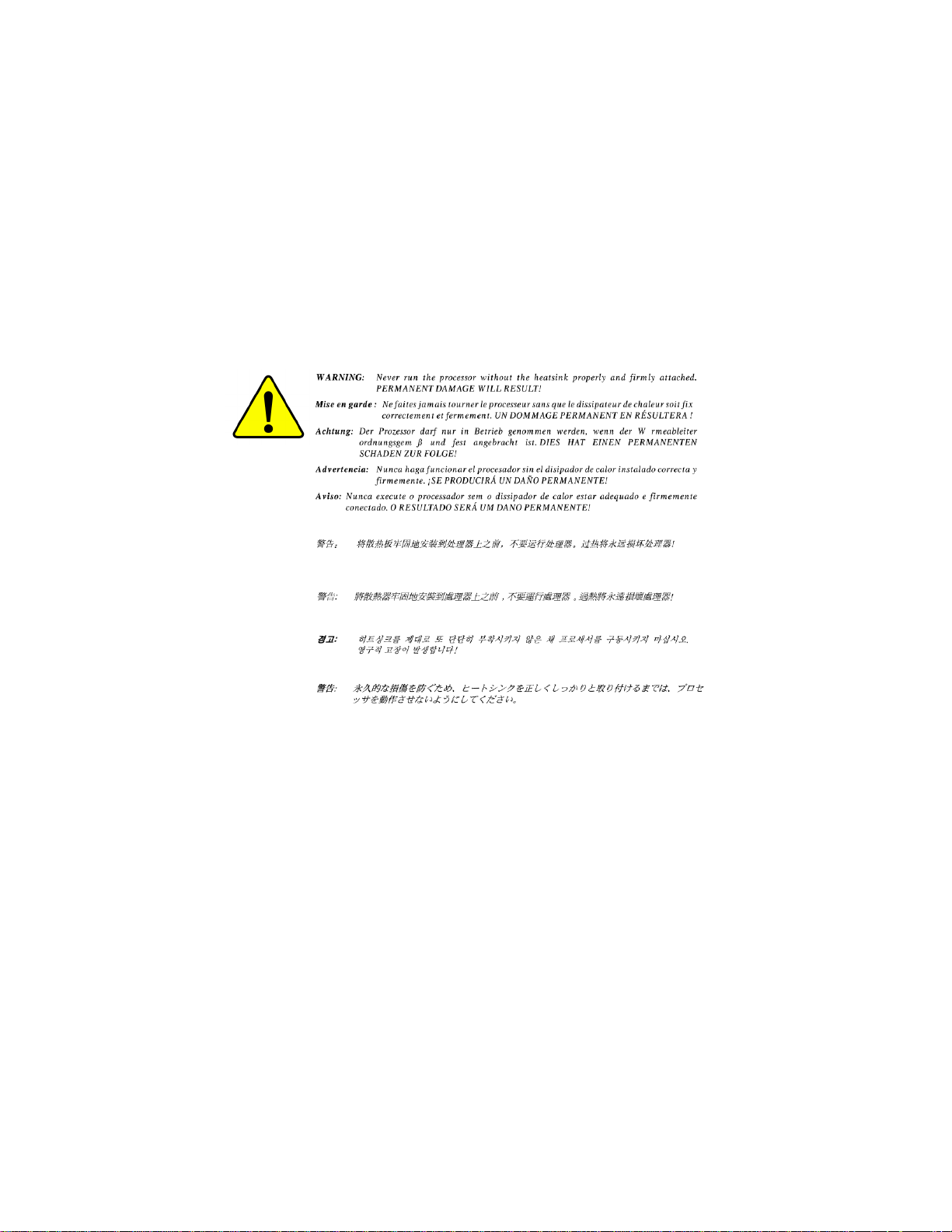
W ARNING!
1. Unplug your computer when working on the inside.
2. Use a grounded wrist strap before handling computer components. If you do not have
one, touch both of your hands to a safely grounded object or to a metal object, such as
the power supply case.
3. Hold components by the edges and try not touch the IC chips, leads or connectors, or
other components.
4. Place components on a grounded antistatic pad or on the bag that came with the
components whenever the components are separated from the system.
5. Ensure that the A TX power supply is switched off before you plug in or remove the ATX
power connector on the motherboard.
Installing the motherboard to the chassis…
If the motherboard has mounting holes, but they don’t line up with the holes on the base and there are
no slots to attach the spacers, do not become alarmed you can still attach the spacers to the mounting
holes. Just cut the bottom portion of the spacers (the spacer may be a little hard to cut off, so be careful
of your hands). In this way you can still attach the motherboard to the base without worrying about short
circuits. Sometimes you may need to use the plastic springs to isolate the screw from the motherboard
PCB surface, because the circuit wire may be near by the hole. Be careful, don’t let the screw contact
any printed circuit write or parts on the PCB that are near the fixing hole, otherwise it may damage the
board or cause board malfunctioning.
* For GA-6IWMT only
- 4 -GA-6IWMT(-C) Motherboard
Page 9

Chapter 1 Introduction
Features Summary
Form Factor 19.0cm x 23.0cm Micro ATX size form factor, 4 layers PCB.
Motherboard GA-6IWMT Series:
GA-6IWMT / 6IWMT-C
CPU Socket 370 processor
supports all new Pentium
package)
supports Celeron processors in FC-PGA & FC-PGA2 package
supports 66/100/133MHz system bus frequency
2nd cache depend on CPU
Chipset Intel 82810E HOST/AGP/SDRAM Controller
FW82801BA (ICH2)
Memory 2 168-pin DIMM sockets
Supports PC-100 SDRAM
Supports only 3.3V SDRAM DIMM
Supports up to 512MB SDRAM (Max)
I/O Control W83627HF
Slots 3 PCI slot supports 33MHz & PCI 2.2 compliant
On-Board IDE 2 IDE bus master (DMA33/A TA66/ATA100) IDE ports for up to 4
ATAPI devices
Supports PIO mode3,4 (UDMA 33/AT A66/ATA100) IDE & A TAPI
CD-ROM
On-Board Peripherals 1 Floppy port supports 2 FDD with 360K, 720K,1.2M, 1.44M
and 2.88M bytes.
1 Parallel port supports Normal/EPP/ECP mode
2 Serial port (COMA, COMB on board)
1 VGA port
4 USB ports (Rear USB x 2, Front USB x 2)
1 IrDA connector for IR
®
III processors (FC-PGA & FC-PGA2
English
- 5 -
to be continued......
Introduction
Page 10

Hardware Monitor CPU/System Fan Revolution detect
English
On-Board Sound AC97 CODEC
On-Board LAN* Build in RTL8101L Chipset
PS/2 Connector PS/2 Keyboard interface and PS/2 Mouse interface
BIOS Licensed AWARD BIOS, 2M bit Flash ROM
Additional Features STR(Suspend-To-RAM)
M Please set the CPU host frequency in accordance with your processor’s specifications.
CPU temperature detect
System V oltage Detect
Line In/Line Out/Mic In/CD In/Game Port
AC Recovery
USB KB/Mouse wake up from S3~S5
Supports @BIOS
Supports Easy Tune 4
TM
TM
We don’t recommend you to set the system bus frequency over the CPU’s specification
because these specific bus frequencies are not the standard specifications for CPU,
chipset and most of the peripherals. Whether your system can run under these specific
bus frequencies properly will depend on your hardware configurations, including CPU,
Chipsets,SDRAM,Cards….etc.
* For GA-6IWMT only
- 6 -GA-6IWMT(-C) Motherboard
Page 11
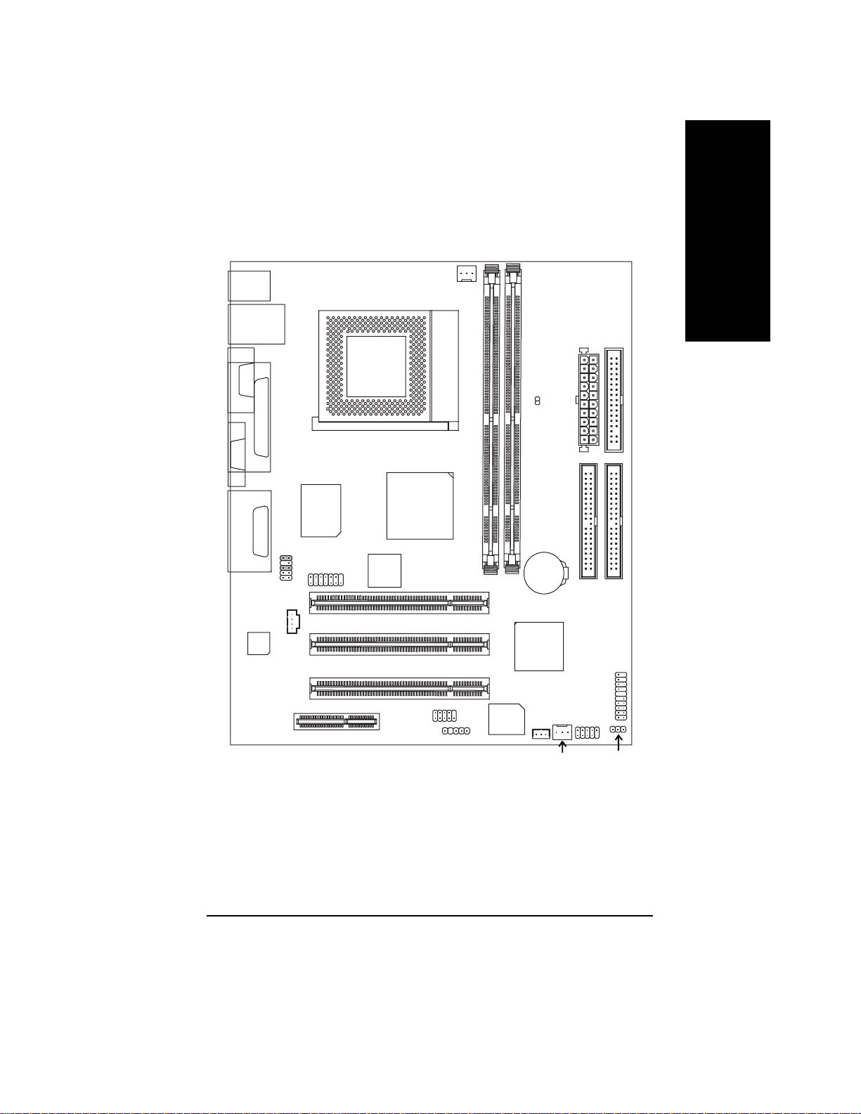
GA-6IWMT(-C) Motherboard Layout
English
KB_MS
USB
COMA
VGA
LINE_OUT
LINE_IN
MIC_IN
CODEC
LPT
GAM E
LAN*
CNR
W83627HF
F_AUDIO
MODEM
CD_IN
SOCKET 370
RTL8101L*
CPU_FAN
82810E
COMB
FLOPPY
LED_CONN
ATX POWWR
GA-6IWMT
DIMM1
PCI1
PCI2
PCI3
IR
BIOS
DIMM2
BATTERY
ICH2
WOL*
F_PANEL
F_USB
IDE2
IDE1
* For GA-6IWMT only
- 7 -
SYS_FAN
PWR_LED
Introduction
Page 12
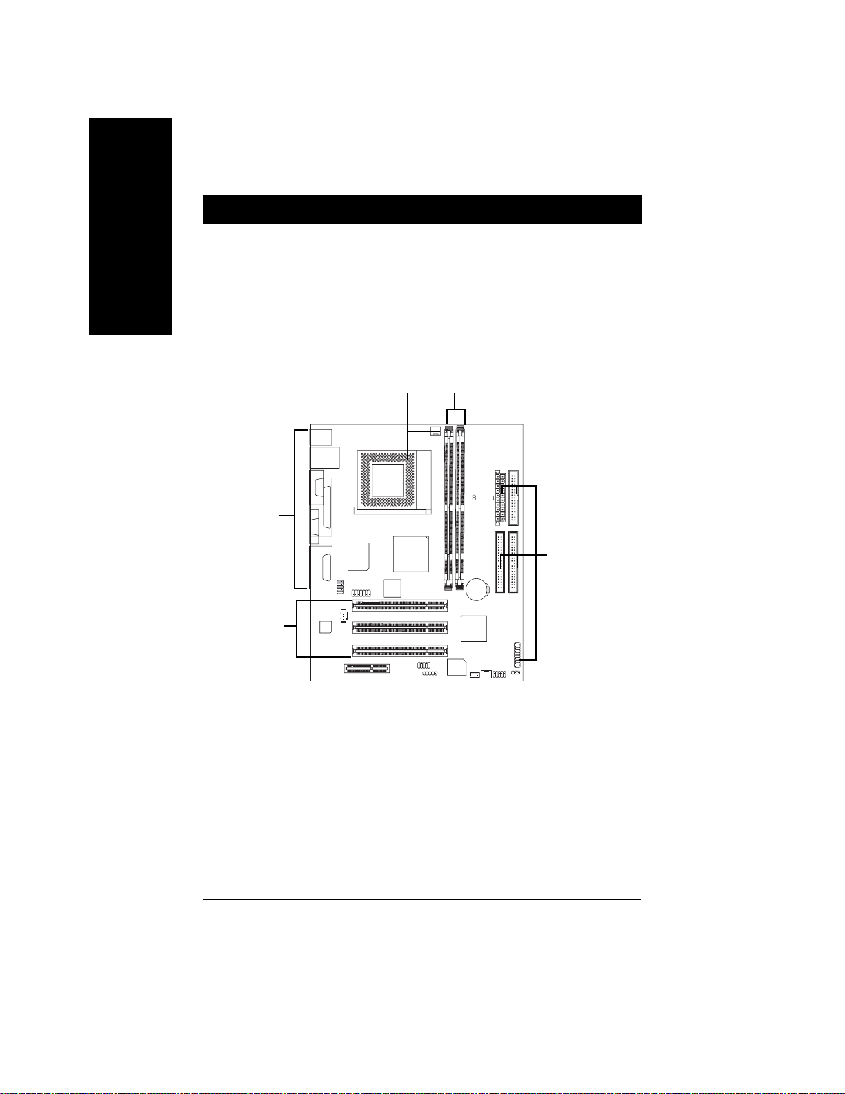
Chapter 2 Hardware Installation Process
T o set up your computer , you must complete the following steps:
English
Step 1- Install the Central Processing Unit (CPU)
Step 2- Install memory modules
Step 3- Install expansion cards
Step 4- Connect ribbon cables, cabinet wires, and power supply
Step 2Step 1
Step 4
Step 5
Step 3
Congratulations! Y ou have accomplished the hardware installation!
Turn on the power supply or connect the power cable to the power outlet. Continue with the
BIOS/software installation.
- 8 -GA-6IWMT(-C) Motherboard
Page 13
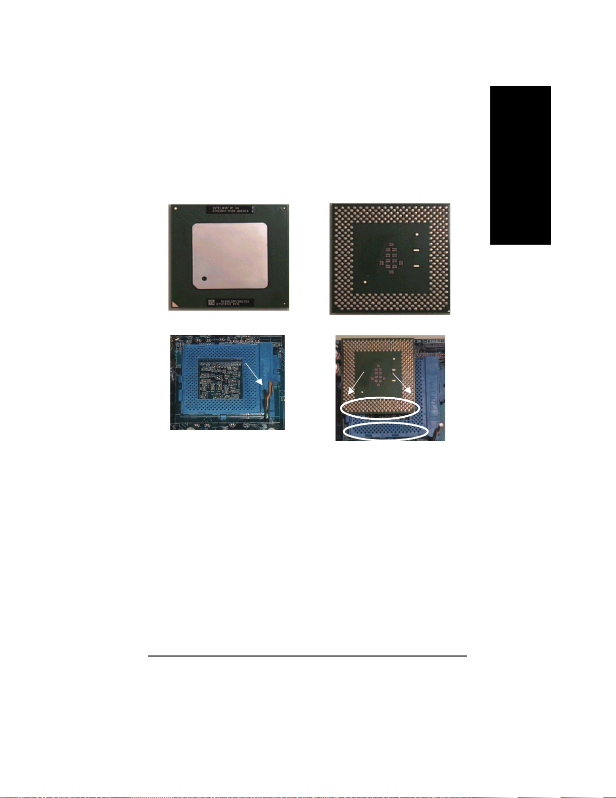
Step 1: Install the Central Processing Unit (CPU)
Step 1-1: CPU Installation
For example: The newest Pentium III processor (FC-PGA2 package).
English
CPU Top View
CPU Bottom View
Socket Actuation Lever
Pin1 indicator
1. Pull up the CPU socket level
and up to 90-degree angle.
M Please make sure the CPU type is supported by the motherboard.
M If you do not match the CPU socket Pin 1 and CPU cut edge well, it will cause
improper installation. Please change the insert orientation.
2. Locate Pin 1 in the socket and look
for a (golden) cut edge on the CPU
upper corner. Then insert the CPU
into the socket.
- 9 -
Hardware Installation Process
Page 14
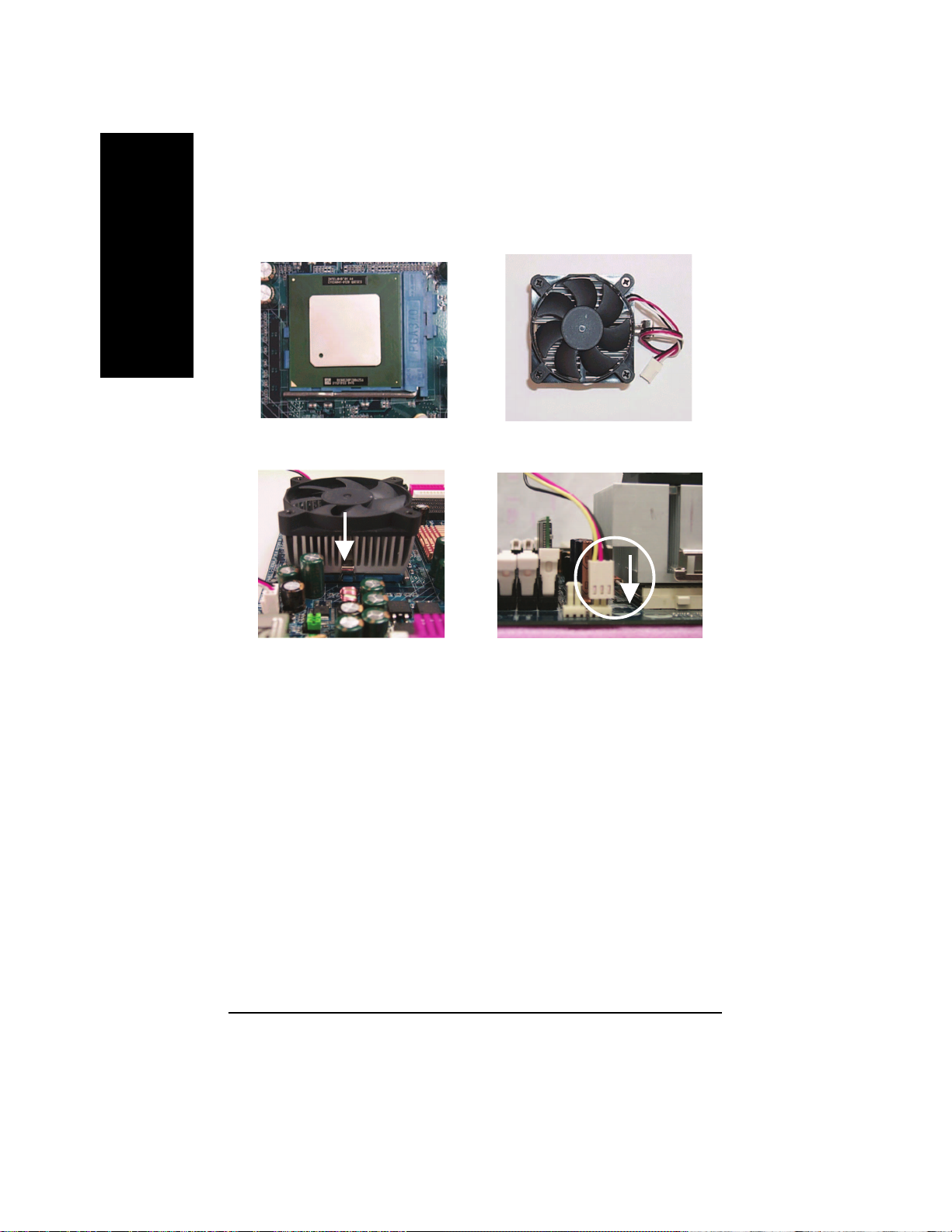
Step 1-2: CPU Heat Sink Installation
English
1. Press down the CPU socket
lever and finish CPU installation.
3. Fasten the heatsink supporting-base
onto the CPU socket on the mainboard.
2. Use qualified fan approved by Intel.
4. Make sure the CPU fan is
plugged to the CPU fan connector,
than install complete.
M Please use Intel approved cooling fan.
M We recommend you to apply the thermal paste to provide better heat
conduction between your CPU and heatsink.
M Make sure the CPU fan power cable is plugged in to the CPU fan connector,
this completes the installation.
M Please refer to CPU heat sink user’s manual for more detail installation
procedure.
- 10 -GA-6IWMT(-C) Motherboard
Page 15
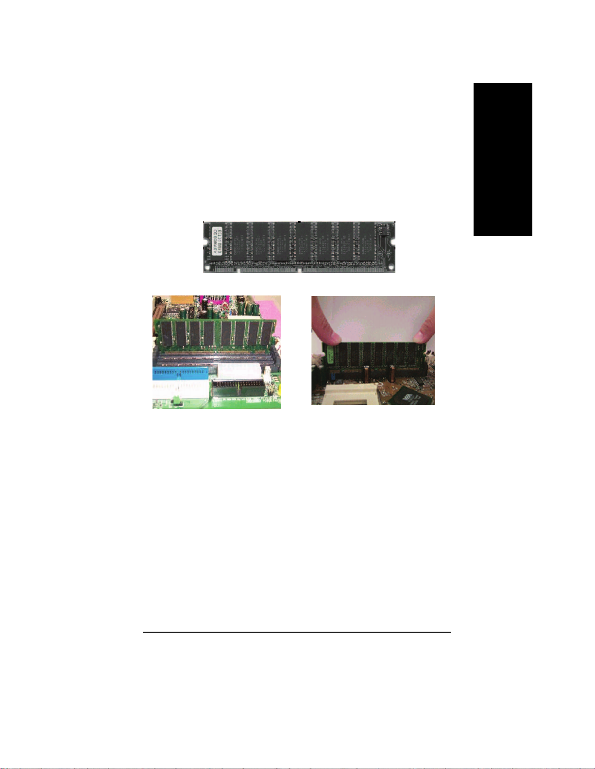
Step 2: Install memory modules
The motherboard has 2 dual in-line memory module (DIMM) sockets support 4 banks. The BIOS will
automatically detects memory type and size. T o install the memory module, just push it vertically into the
DIMM Slot .The DIMM module can only fit in one direction due to the two notch. Memory size can vary
between sockets.
SDRAM
English
1. The DIMM slot has two notch, so the
DIMM memory module can only fit in
one direction.
3. Close the plastic clip at both edges of the DIMM slots to lock the DIMM module.
Reverse the installation steps when you wish to remove the DIMM module.
2. Insert the DIMM memory module
vertically into the DIMM slot. Then
push it down.
M When STR/DIMM LED is ON, do not install/remove SDRAM from socket.
M Please note that the DIMM module can only fit in one direction due to the two
notches. Wrong orientation will cause improper installation. Please change
the insert orientation.
- 11 -
Hardware Installation Process
Page 16
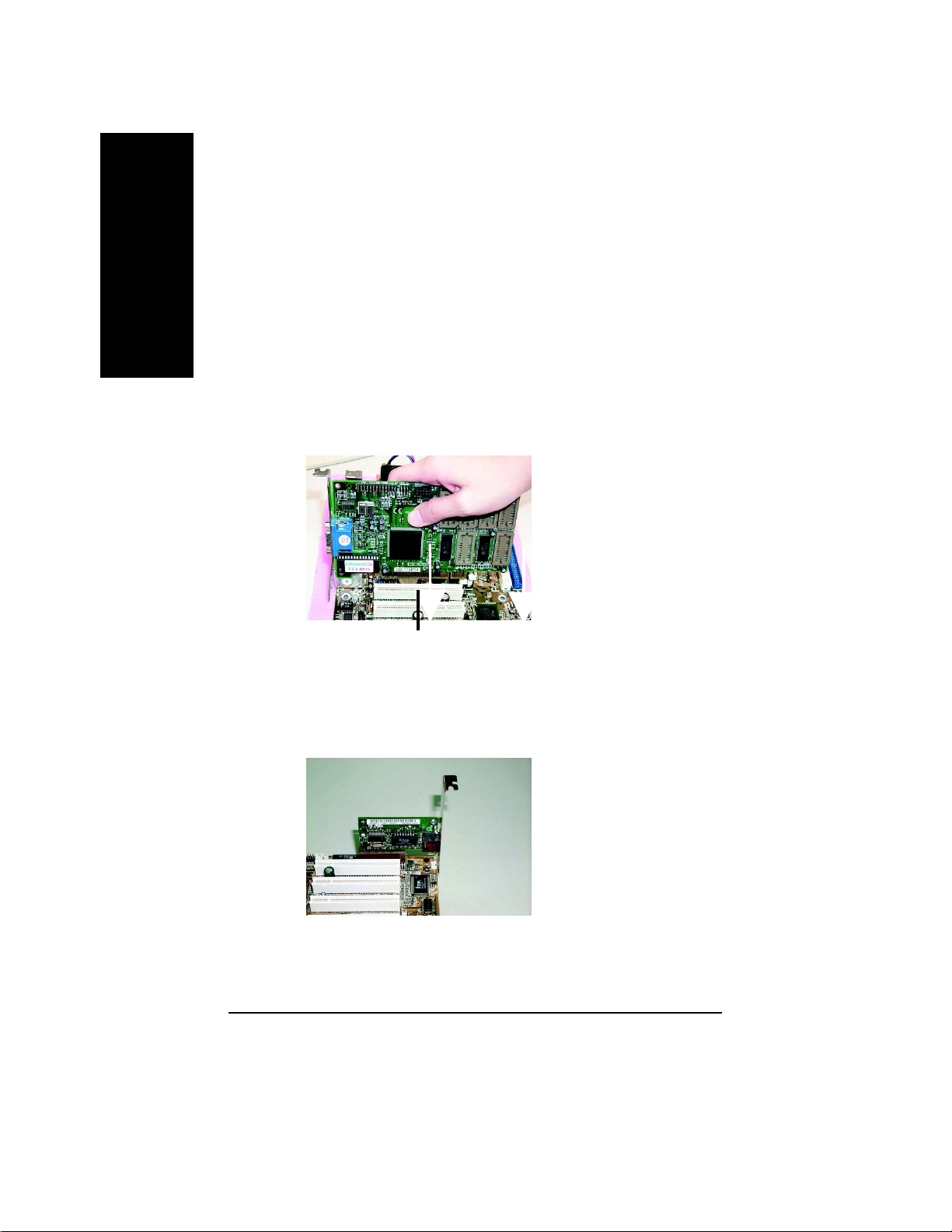
Step 3: Install expansion cards
1. Read the related expansion card’s instruction document before install the expansion card into
English
2. Remove your computer's chassis cover, necessary screws and slot bracket from the computer.
3. Press the expansion card firmly into expansion slot in motherboard.
4. Be sure the metal contacts on the card are indeed seated in the slot.
5. Replace the screw to secure the slot bracket of the expansion card.
6. Replace your computer’s chassis cover.
7. Power on the computer, if necessary, setup BIOS utility of expansion card from BIOS.
8. Install related driver from the operating system.
the computer.
PCI Slot
Issues To Beware Of When Installing CNR
Please use standard CNR card like the one in order to avoid mechanical problem.
Standard CNR Card
- 12 -GA-6IWMT(-C) Motherboard
Page 17
Step 4: Connect ribbon cables, cabinet wires, and power
supply
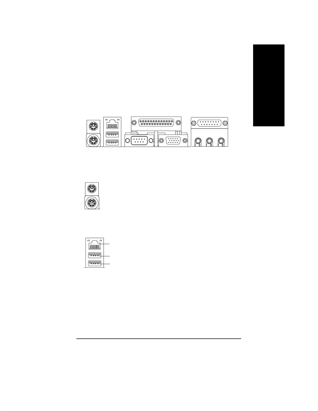
Step 4-1: I/O Back Panel Introduction
English
u
v
u PS/2 Keyboard and PS/2 Mouse Connector
PS/2 Mouse Connector
(6 pin Female)
PS/2 Keyboard Connector
(6 pin Female)
ØThis connector supports standard PS/2 keyboard
and PS/2 mouse.
v USB & LAN Connector
ØBefore you connect your device(s) into USB
connector(s), please make sure your device(s)
LAN*
USB 0
USB 1
such as USB keyboard,mouse, scanner, zip,
speaker..etc. Have a standard USB interface.
Also make sure your OS supports USB controller.
If your OS does not support USB controller, please
contact OS vendor for possible patch or driver
upgrade. For more information please contact your
OS or device(s) vendors.
w
x
y
* For GA-6IWMT Only
- 13 -
Hardware Installation Process
Page 18
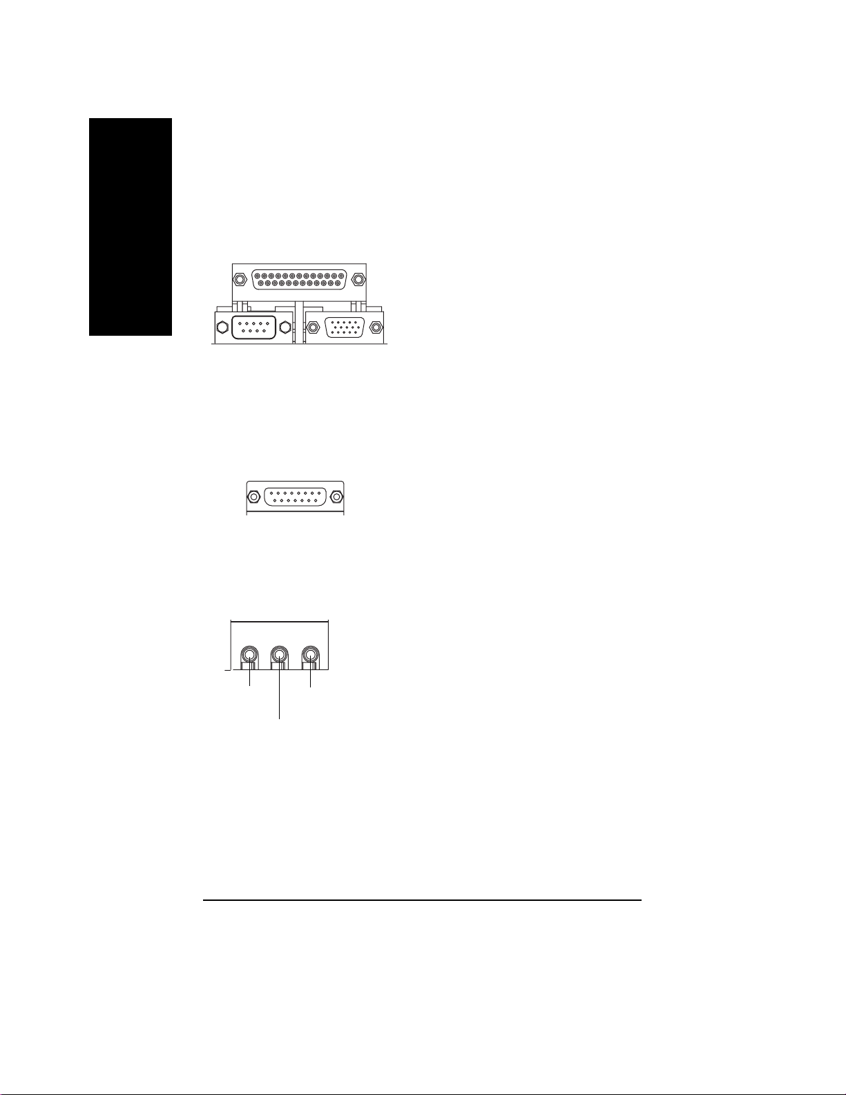
w Parallel Port , Serial Port and VGA Port (LPT/COMA/VGA)
English
x Game /MIDI Ports
y Audio Connectors
Parallel Port
(25 pin Female)
COMA VGA
Serial Port
(9 pin Male)
Joystick/ MIDI (15 pin Female)
VGA Port
(15 pin Female)
ØThis connector supports 1 standard COM port
,1 Parallel port and 1 VGA port. Device like
printercan be connected to Parallel port ; mouse
and modem etc can be connected to Serial ports.
ØThis connector supports joystick, MIDI keyboard
and other relate audio devices.
Ø After install onboard audio driver, you may
connect speaker to Line Out jack, micro phone to
MIC In jack. Device like CD-ROM , walkman etc
can be connected to Line-In jack.
Line Out
MIC In
Line In
- 14 -GA-6IWMT(-C) Motherboard
Page 19
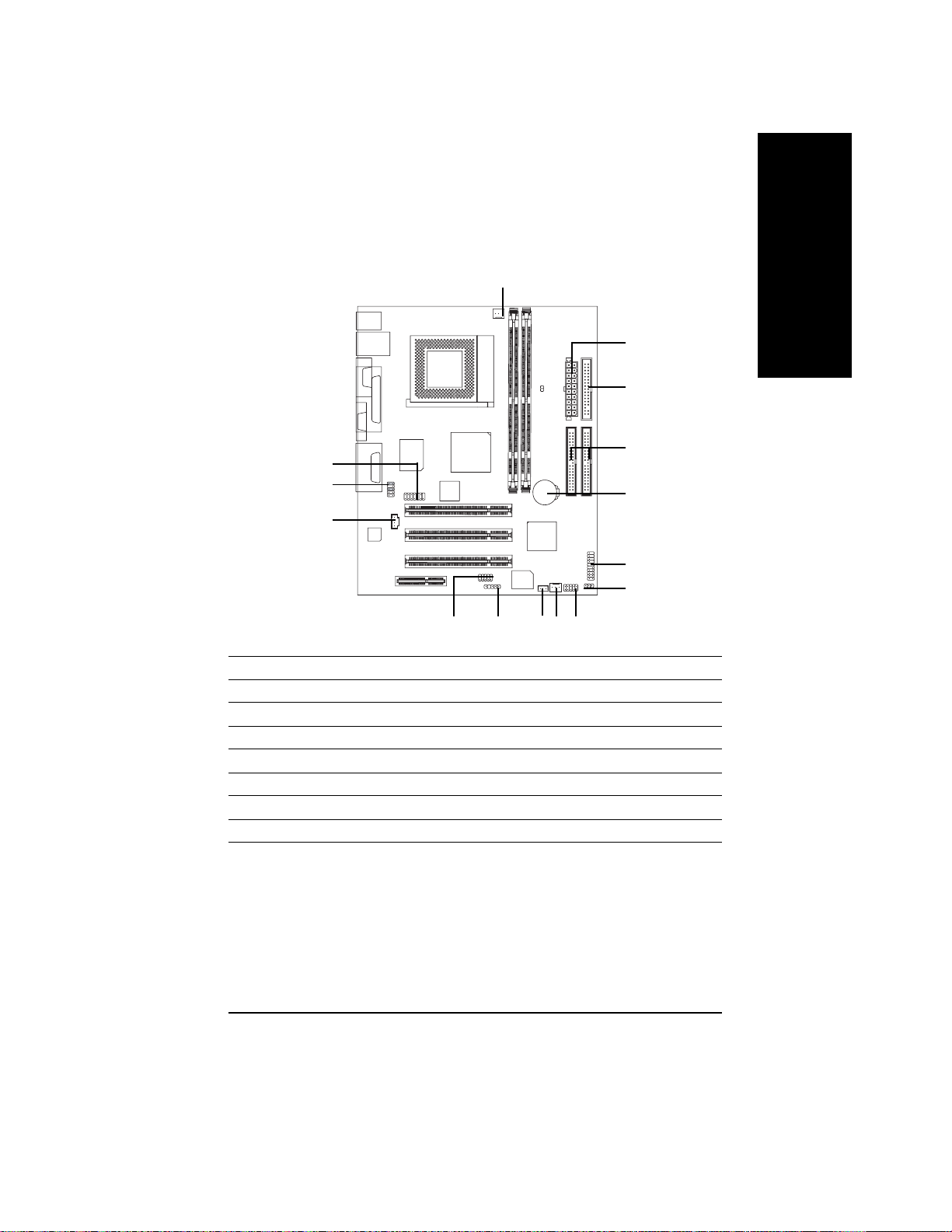
Step 4-2: Connectors Introduction
1
14
9
10
13
11
1) CPU_FAN 9) F_AUDIO
2) SYS_FAN 10) CD_IN
3) ATX 11) IR
4) IDE1/IDE2 12)F_USB
5) FDD 13) COMB
6) PWR_LED 14)MODEM
7) F_PANEL 15) WOL*
8) BATTERY
15
English
3
5
4
8
7
6
2
12
* For GA-6IWMT Only
- 15 -
Hardware Installation Process
Page 20

1) CPU_FAN (CPU FAN Connector)
English
Please note, a proper installation of the CPU cooler is essential to prevent the CPU from running
under abnormal condition or damaged by overheating.The CPU fan connector supports Max.
current up to 600 mA.
1
Pin No. Definition
1 GND
2 +12V
3 Sense
2) SYS_FAN (System FAN Connector)
This connector allows you to link with the cooling fan on the system case to lower the system
temperature.
Pin No. Definition
1 GND
1
2 +12V
3 Sense
- 16 -GA-6IWMT(-C) Motherboard
Page 21
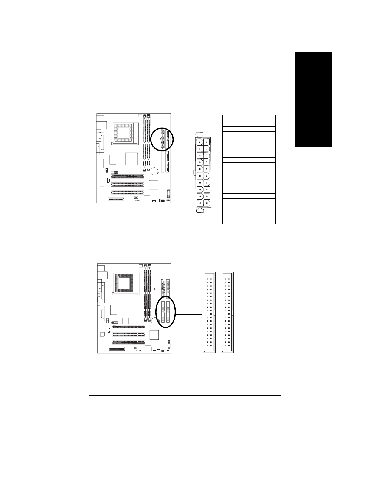
3) ATX_POWER (A TX Power)
AC power cord should only be connected to your power supply unit after ATX power cable and
otherrelated devices are firmly connected to the mainboard.
Pin No. Definition
1 3.3V
2 3.3V
3 GND
11
20
4 VCC
1
5 GND
6 VCC
7 GND
8 Power Good
9 5V SB(stand by +5V)
10 +12V
11 3.3V
12 -12V
13 GND
14 PS_ON(softOn/Off)
15 GND
16 GND
10
17 GND
18 -5V
19 VCC
20 VCC
4) IDE1/ IDE2(IDE1/IDE2 Connector)
Please connect first harddisk to IDE1 and connect CDROM to IDE2. The red stripe of the ribbon
cable must be the same side with the Pin1.
English
- 17 -
40
2
IDE2
39
1
IDE1
Hardware Installation Process
Page 22
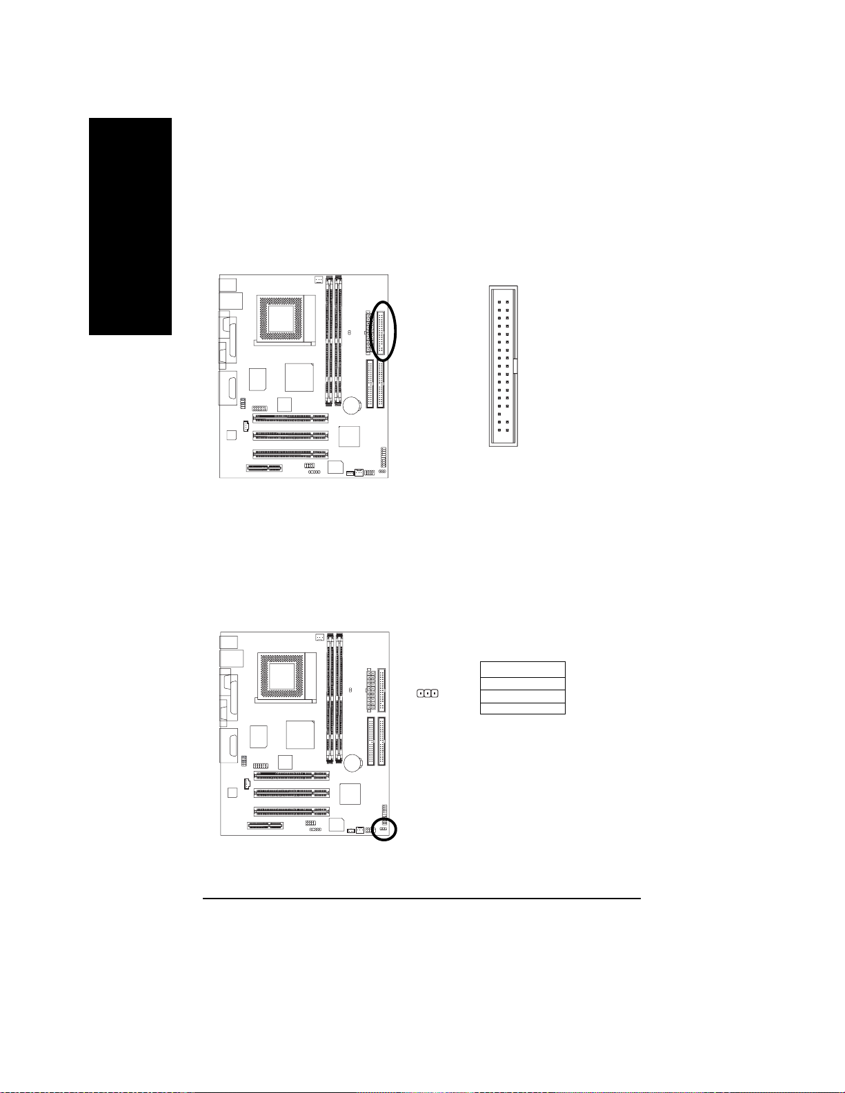
5) FDD (Floppy Connector)
English
Please connect the floppy drive ribbon cables to FDD. It supports 360K,720K,1.2M,1.44M and
2.88Mbytes floppy disk types. The red stripe of the ribbon cable must be the same side with the
Pin1.
34
2
33
1
6) PWR_LED
PWR_LED is connect with the system power indicator to indicate whether the system is on/off. It
will blink when the system enters suspend mode. If you use dual color LED, power LED will turn
to another color.
1
Pin No. Definition
1 MPD+
2 MPD3 MPD-
- 18 -GA-6IWMT(-C) Motherboard
Page 23

7) F_PANEL (2x10 pins connector)
Please connect the power LED, PC peaker, reset switch and power switch etc of your
chassis front panel to the F_PANEL connector according to the pin assignment above.
19
PW-
SPK-
SPK+
PW+
MPD-
20
MPD+
1
1
1
1
1
2
1
IDE Hard Disk
Active LED
HD+
NC
RSE+
RSE-
HD-
Speaker
Connector
Soft Power
Connector
Message LED/Power/
Sleep LED
HD (IDE Hard Disk Active LED) Pin 1: LED anode(+)
(Blue) Pin 2: LED cathode(-)
SPK (Speaker Connector) Pin 1: VCC(+)
(Amber) Pin 2- Pin 3: NC
Pin 4: Data(-)
RES (Reset Switch) Open: Normal Operation
(Green) Close: Reset Hardware System
PW (Soft Power Connector) Open: Normal Operation
(Red) Close: Power On/Off
MSG(Message LED/Power/ Pin 1: LED anode(+)
Sleep LED)(Y ellow) Pin 2: LED cathode(-)
NC( Purple) N C
English
Reset Switch
8) BA TTERY (Battery)
If you want to erase CMOS...
1.Turn OFF the computer and unplug the power cord.
2.Remove the battery, wait for 30 second.
3.Re-install the battery.
4.Plug the power cord and turn ON the computer.
- 19 -
+
CAUTION
v Danger of explosion if battery is incorrectly
replaced.
v Replace only with the same or equivalent
type recommended by the manufacturer.
v Dispose of used batteries according to the
manufacturer’s instructions.
Hardware Installation Process
Page 24
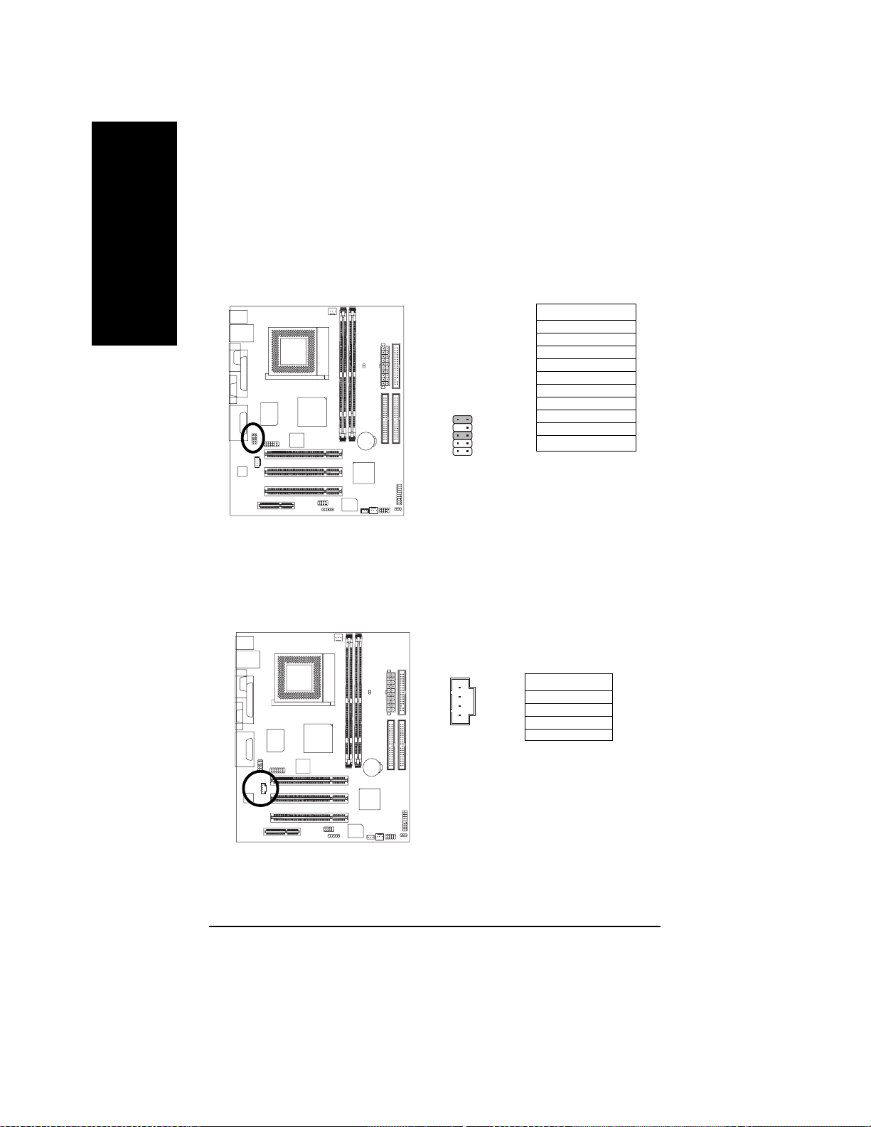
9) F_AUDIO (F_AUDIO Connector)
English
10) CD_IN (CD IN,Blank)
If you want to use Front Audio connector, you must remove 5-6, 9-10 Jumper. In order to utilize the
front audio header, your chassis must have front audio connector. Also please make sure the pin
assigment on the cable is the same as the pin assigment on the MB header. To find out if the chassis
you are buying support front audio connector, please contact your dealer.
Pin No. Definition
1 MIC
2 GND
3 REF
4 POWER
5 FrontAudio(R)
6 RearAudio(R)
7 Reserved
9
10
2
1
8 No Pin
9 FrontAudio (L)
10 RearAudio(L)
Connect CD-ROM or DVD-ROM audio out to the connector.
Pin No. Definition
1 CD-L
1
2 GND
3 GND
4 CD_R
- 20 -GA-6IWMT(-C) Motherboard
Page 25

11)IR
Be careful with the polarity of the IR connectorwhile you connect the IR. Please contact you nearest
dealer for optional IR device.
Pin No. Definition
1 VCC(+5V)
1
5
2NC
3 IR Data Input
4 GND
5 IR DAta Output
12)F_ USB(Front USB Connector, Yellow )
Be careful with the polarity of the front USB connector. Check the pin assignment while you
connect the front USB cable. Please contact your nearest dealer for optional front USB
cable.
English
- 21 -
Pin No. Definition
1 Power
2
10
1
9
2 Power
3 USB DX4 USB Dy5 USB DX+
6 USB Dy+
7 GND
8 GND
9 No Pin
USB Over Current
10
Hardware Installation Process
Page 26

13) COM B(COM B Connector)
Be careful with the polarity of the COMB connector. Check the pin assignment while you
connect the COMB cable.Please contact your nearest dealer for optional COMB cable.
English
14) MODEM
129
Please contact your nearest dealer for optional Modem card.
2
1
Pin No. Definition
1 NDCDB2 NSINB
3 NSOUTB
4 NDTRB5 GND
6 NDSTRB-
10
14
13
7 NRTSB8 NCTSB9 NRIB10 N C
Pin No. Definition
1 GND
2 VDD33
3 AC OUT
4 VCC
5 AC BCK
6 +12V
7 ACDIN
8 VAUX33
9 AC DOUT
10 N C
1 1 AC SYNC
12 N C
13 AC RSTB
14 No pin
- 22 -GA-6IWMT(-C) Motherboard
Page 27

15)WOL (Wake On Lan) *
This connector allows the remove servers to manage the system that installed this
mainboard via your network adapter which also supports WOL.
English
1
Pin No. Definition
1 +5V SB
2 GND
3 Signal
* For GA-6IWMT Only
- 23 -
Hardware Installation Process
Page 28

English
- 24 -GA-6IWMT(-C) Motherboard
Page 29

Chapter 3 BIOS Setup
BIOS Setup is an overview of the BIOS Setup Program. The program that allows users to modify the
basic system configuration. This type of information is stored in battery-backed CMOS RAM so that it
retains the Setup information when the power is turned off.
ENTERING SETUP
Power ON the computer and press <Del> immediately will allow you to enter Setup. If the message
disappears before you respond and you still wish to enter Setup, restart the system to try again by turning
it OFF then ON or pressing the “RESET” bottom on the system case. You may also restart by
simultaneously press <Ctrl> - <Alt>- <Del> keys.
CONTROL KEYS
<á> Move to previous item
<â> Move to next item
<ß> Move to the item in the left hand
<à> Move to the item in the right hand
<Esc> Main Menu - Quit and not save changes into CMOS Status Page Setup Menu and
Option Page Setup Menu - Exit current page and return to Main Menu
<+/PgUp> Increase the numeric value or make changes
<-/PgDn> Decrease the numeric value or make changes
<F1> General help, only for Status Page Setup Menu and Option Page Setup Menu
<F2> Item help
<F3> Reserved
<F4> Reserved
<F5> Restore the previous CMOS value from CMOS, only for Option Page Setup Menu
<F6> Load the default CMOS value from BIOS default table, only for Option Page Setup
Menu
<F7> Load the Setup Defaults
<F8> Reserved
<F9> Reserved
<F10> Save all the CMOS changes, only for Main Menu
English
- 25 - BIOS Setup
Page 30

GETTING HELP
The on-line description of the highlighted setup function is displayed at the bottom of the screen.
English
Press F1 to pop up a small help window that describes the appropriate keys to use and the possible
selections for the highlighted item. T o exit the Help Window press <Esc>.
The Main Menu (For example: BIOS Ver. :F2)
Once you enter AWARD BIOS CMOS Setup Utility, the Main Menu (Figure 1) will appear on the
screen. The Main Menu allows you to select from eight setup functions and two exit choices. Use arrow
keys to select among the items and press <Enter> to accept or enter the sub-menu.
Main Menu
Status Page Setup Menu / Option Page Setup Menu
CMOS Setup Utility-Copyright (C) 1984-2003 Award Software
}Standard CMOS Features }Frequency/Voltage Control
} Advanced BIOS Features Load Fail-Safe Defaults
} Advanced Chipset Features Load Optimized Defaults
}Integrated Peripherals Set Supervisor Password
} Power Management Setup Set User Password
}PnP/PCI Configurations Save & Exit Setup
}PC Health Status Exit Without Saving
ESC:Quit higf:Select Itect
F8:Q-Flash F10:Save & Exit Setup
Time, Date, Hard Disk Type...
Figure 1: Main Menu
l Standard CMOS Features
This setup page includes all the items in standard compatible BIOS.
l Advanced BIOS Features
This setup page includes all the items of Award special enhanced features.
l Advanced Chipset Features
This setup page includes all the items of chipset special features.
- 26 -GA-6IWMT(-C) Motherboard
Page 31

l Integrated Peripherals
This setup page includes all onboard peripherals.
l Power Management Setup
This setup page includes all the items of Green function features.
l PnP/PCI Configurations
This setup page includes all the configurations of PCI & PnP ISA resources.
l PC Health Status
This setup page is the System auto detect T emperature, voltage, fan, speed.
l Frequency/Voltage Contr ol
This setup page is control CPU’s clock and frequency ratio.
l Load Fail-Safe Defaults
Fail-Safe Defaults indicates the value of the system parameters which the system would
be in safe configuration.
l Load Optimized Defaults
Optimized Defaults indicates the value of the system parameters which the system would
be in best performance configuration.
l Set Supervisor password
Change, set, or disable password. It allows you to limit access to the system and Setup,
or just to Setup.
l Set User password
Change, set, or disable password. It allows you to limit access to the system.
l Save & Exit Setup
Save CMOS value settings to CMOS and exit setup.
l Exit Without Saving
Abandon all CMOS value changes and exit setup.
English
- 27 - BIOS Setup
Page 32

Standard CMOS Features
English
CMOS Setup Utility-Copyright (C) 1984-2003 Award Software
Standard CMOS Features
Date (mm:dd:yy) Thu, Aug 21 2003
Time (hh:mm:ss) 22:31:24
} IDE Primary Master [Press Enter None]
} IDE Primary Slave [Press Enter None]
} IDE Secondary Master [Press Enter None]
} IDE Secondary Slave [Press Enter None]
Drive A [1.44M, 3.5"]
Drive B [None]
Floppy 3 Mode Support [Disabled]
Halt On [All, But Keyboard]
Base Memory 640K
Extended Memory 126M
Total Memory 127M
higf: Move Enter:Select +/-/PU/PD:Value F10:Save ESC:Exit F1:General Help
F5:Previous Values F6:Fail-Safe Defaults F7:Optimized Defaults
Figure 2: Standard CMOS Features
Item Help
Menu Level u
Change the day,
month,year
<Week>
Sun. to Sat.
<Month>
Jan. to Dec.
<Day>
1 to 31(or maximun
allowed in the month.)
<year>
1999 to 2098
F Date
The date format is <month>, <day>, <year>, <week>.
8Month The month, Jan. Through Dec.
8 Day The day, from 1 to 31 (or the maximum allowed in the month)
8Year The year, from 1990 through 2099
8Week The week, from Sun to Sat, determined by the BIOS and is display only
- 28 -GA-6IWMT(-C) Motherboard
Page 33

FTime
The times format in <hour> <minute> <second>. The time is calculated base on the 24-hour militarytime clock. For example, 1 p.m. is 13:00:00.
FPrimary Master, Slave / Secondary Master, Slave
The category identifies the types of hard disk from drive C to F that has been installed in the
computer. There are two types: auto type, and manual type. Manual type is user-definable; Auto
type which will automatically detect HDD type.
Note that the specifications of your drive must match with the drive table. The hard disk will not work
properly if you enter improper information for this category.
If you select User T ype, related information will be asked to enter to the following items. Enter the
information directly from the keyboard and press <Enter>. Such information should be provided in
the documentation form your hard disk vendor or the system manufacturer.
8CYLS. Number of cylinders
8HEADS number of heads
8 PRECOMP write precomp
8LANDZONE Landing zone
8 SECTORS number of sectors
If a hard disk has not been installed select NONE and press <Enter>.
FFloppy Drive A / Drive B
The category identifies the types of floppy disk drive A or drive B that has been installed in the
computer.
8None No floppy drive installed
8360K, 5.25 ". 5.25 inch PC-type standard drive; 360K byte capacity.
81.2M, 5.25 ". 5.25 inch AT-type high-density drive; 1.2M byte capacity
(3.5 inch when 3 Mode is Enabled).
8720K, 3.5 ". 3.5 inch double-sided drive; 720K byte capacity
81.44M, 3.5 ". 3.5 inch double-sided drive; 1.44M byte capacity.
82.88M, 3.5 ". 3.5 inch double-sided drive; 2.88M byte capacity.
English
- 29 - BIOS Setup
Page 34

C Floppy 3 Mode Support (for Japan Area)
English
CHalt on
C Memory
8Disabled Normal Floppy Drive. (Default value)
8Drive A Drive A is 3 mode Floppy Drive.
8Drive B Drive B is 3 mode Floppy Drive.
8Both Drive A & B are 3 mode Floppy Drives.
The category determines whether the computer will stop if an error is detected during power up.
8NO Errors The system boot will not stop for any error that may be detected
and you will be prompted.
8All Errors Whenever the BIOS detects a non-fatal error the system will be stopped.
8All, But Keyboar The system boot will not stop for a keyboard error; it will stop for
all other errors. (Default value)
8All, But Diskette The system boot will not stop for a disk error; it will stop for all
other errors.
8All, But Disk/Key The system boot will not stop for a keyboard or disk error; it will
stop for all other errors.
The category is display-only which is determined by POST (Power On Self T est) of the BIOS.
Base Memory
The POST of the BIOS will determine the amount of base (or conventional) memory
installed in the system.
The value of the base memory is typically 512 K for systems with 512 K memory
installed on the motherboard, or 640 K for systems with 640 K or more memory
installed on the motherboard.
Extended Memory
The BIOS determines how much extended memory is present during the POST.
This is the amount of memory located above 1 MB in the CPU’s memory
address map.
- 30 -GA-6IWMT(-C) Motherboard
Page 35

Advanced BIOS Features
CMOS Setup Utility-Copyright (C) 1984-2001 Award Software
Advanced BIOS Features
BIOS Flash Protection [Auto]
#Processor Serial Number [Disabled]
First Boot Device [Floppy]
Second Boot Device [HDD-0]
Third Boot Device [CDROM]
Boot Up Floppy Seek [Disabled]
Boot Up Num-Lock [On]
Password Check [Setup]
Interrupt Mode [APIC]
HDD S.M.A.R.T. Capability [Disabled]
Delay For HDD (Secs) [0]
higf: Move Enter:Select +/-/PU/PD:Value F10:Save ESC:Exit F1:General Help
F5:Previous Values F6:Fail-Safe Defaults F7:Optimized Defaults
Figure 3: Advanced BIOS Features
#System will detect automatically and show up when you install the Pentium R !!!
processor.
C BIOS Flash Protection
This field lets you determine the states that flash BIOS.
8Auto BIOS enables flash write access automatically when updating BIOS data/
DMI/ESCD. (Default Value)
8Enabled During POST, DMI/ESCD would not be updated. But flash tools can update
BIOS always.
Item Help
Menu Level u
[Auto]
Allows BIOS to updte
flash data during POST.
It Still Prevents other
unauthorized utilities to
update flash
[Enable]
Always prevent BIOS
and unauthorized
utilities to update flash
English
CProce ssor Seri al Number
This item will show up when you install the PentiumR !!! processor.
8Enabled PentiumR !!! Processor Number Feature. (Default value)
8Disabled Disabled this function.
- 31 - BIOS Setup
Page 36

C First / Second / Third Boot device
English
C Boot Up Floppy Seek
8 Floppy Select your boot device priority by Floppy.
8LS120 Select your boot device priority by LS120.
8HDD-0~3 Select your boot device priority by HDD-0~3.
8SCSI Select your boot device priority by SCSI.
8 CDROM Select your boot device priority by CDROM.
8ZIP Select your boot device priority by ZIP.
8USB-FDD Select your boot device priority by USB-FDD.
8USB-ZIP Select your boot device priority by USB-ZIP.
8 USB-CDROM Select your boot device priority by USB-CDROM.
8USB-HDD Select your boot device priority by USB-HDD.
8 LAN Select your boot device priority by LAN.
8Disabled Select your boot device priority by Disabled
During POST, BIOS will determine the floppy disk drive installed is 40 or 80 tracks. 360 K type is
40 tracks 720 K, 1.2 M and 1.44 M are all 80 tracks.
8Enabled BIOS searches for floppy disk drive to determine it is 40 or 80 tracks. Note
that BIOS can not tell from 720 K, 1.2 M or 1.44 M drive type as they are
all 80tracks.
8Disabled BIOS will not search for the type of floppy disk drive by track number. Note
that there will not be any warning message if the drive installed is 360 K.
(Default value)
C Boot Up NumLock
8On Keypad is number keys. (Default value)
8Off Keypad is arrow keys.
C Password Check
This category allows you to limit access to the system and Setup, or just to Setup.
8 System The system can not boot and can not access to Setup page will be denied
if the correct password is not entered at the prompt.
8Setup The system will boot, but access to Setup will be denied if the correct
password is not entered at the prompt. (Default value)
- 32 -GA-6IWMT(-C) Motherboard
Page 37

CInterrupt Mode
8APIC Through IOAPIC generate more IRQ for system use.(Default value)
8PIC Use AT stantard IRQ controlles to generate IRQ.
When you already have IOAPIC enable system and want to upgrade the system please note, since
running an IOAPIC enabled OS (like Windows NT,Windows 2000, Windows XP...) system with none
IOAPIC HW support will cause the system to hang. Following are some situations users might run into:
1.An IOAPIC enabled OS and change the BIOS setting from IOAPIC to PIC, this will cause your
system to hang.
2.An IOAPIC enabled OS and change a processor from IOAPIC supported to none IOAPIC support
(like VIA C3, Cyrix
®
MII, Cyrix® III), and some Intel Pentium® !!!, CeleronTM Processor(certain lot
number), this will disable the IOAPIC in the BIOS and cause the system to hang.
When above situation happened you will have to reinstall the OS.
CHDD S.M.A.R.T. Capability
8Enabled Enabled HDD S.M.A.R.T. Capability.
8Disabled Disabled HDD S.M.A.R.T. Capability. (Default value)
CDelay For HDD (Secs)
80~15 Set Delay Time For HDD.
English
- 33 - BIOS Setup
Page 38

Advanced Chipset Features
English
SDRAM CAS Latency Time [Auto] Item Help
SDRAM Cycle Time Trac/Trc [Auto] Menu Level
SDRAM RAS-to-CAS Delay [Auto]
SDRAM RAS Precharge Time [Auto]
CPU Latency Timer [Disabled]
Delay Transaction [Enable]
AGP Graphics Aperture Size [64MB]
SDRAM Buffer Strength [Auto]
CSDRAM CAS latency Ti me
CMOS Setup Utility-Copyright (C) 1984-2001 Award Software
Advanced Chipset Features
higf: Move Enter:Select +/-/PU/PD:Value F10:Save ESC:Exit F1:General Help
F5:Previous Values F6:Fail-Safe Defaults F7:Optimized Defaults
Figure 4: Advanced Chipset Features
83 For Slower SDRAM DIMM module.
82 For Fastest SDRAM DIMM module.
8Auto Set SDRAM CAS latency to Auto.(Default value)
CSDRAM Cycle T i me Trac/Trc
8 5/7 Set SDRAM Cycle Time Trac/Trc to 5/7SCLKs.
8 6/8 Set SDRAM Cycle Time Trac/Trc to 6/8SCLKs.
8Auto Set SDRAM Cycle Time Trac/Trc to Auto.(Default value)
CSD RAM RAS- to-CAS Delay
83 Set SDRAM RAS-to-CAS delay 3 SCLKs.
82 Set SDRAM RAS-to-CAS delay 2 SCLKs.
8Auto Set SDRAM RAS-to-CAS delay to Auto.(Default value)
CSDRAM RAS Pre charge T i me
83 Set SDRAM RAS Precharge Time to 3.
82 Set SDRAM RAS Precharge Time to 2.
8Auto Set SDRAM RAS Precharge to Auto.(Default value)
- 34 -GA-6IWMT(-C) Motherboard
Page 39

C CPU Latency Timer
8Disanled Disabled CPU Latency Timer. (Default value)
8Enabled Enabled CPU Latency Timer.
F Delay Tra nsaction
8Enabled Enabled PCI Delay Transaction. (Default Value)
8Disabled Disabled PCI Delay Transaction.
FAGP Gra phics Aper ture Size (MB)
864 Set AGP Graphics Aperture Size to 64 MB. (Default Value)
8Disabled Disable this function.
CSDRAM Buffer Strength
8Auto Set SDRAM Buffer Strength to Auto. (Default value)
84X Set SDRAM Buffer Strength to 4X.
83X Set SDRAM Buffer Strength to 3X.
82X Set SDRAM Buffer Strength to 2X.
81X Set SDRAM Buffer Strength to 1X.
English
- 35 - BIOS Setup
Page 40

Integrated Peripherals
English
IDE1 Conductor Cable [Auto]
IDE2 Conductor Cable [Auto]
On-Chip Primary PCI IDE [Enabled]
On-Chip Secondary PCI IDE [Enabled]
IDE Primary Master PIO [Auto]
IDE Primary Slave PIO [Auto]
IDE Secondary Master PIO [Auto]
IDE Secondary Slave PIO [Auto]
IDE Primary Master UDMA [Auto]
IDE Primary Slave UDMA [Auto]
IDE Secondary Master UDMA [Auto]
IDE Secondary Slave UDMA [Auto]
USB Controller [Enabled]
USB Keyboard Support [Disabled]
USB Mouse Support [Disabled]
Init Display First [PCI Slot]
AC97 Audio [Auto]
AC97 Modem [Auto]
Onboard LAN Device [Enabled]
Onboard LAN Boot ROM [Disabled]
Onboard Modem Function [Disabled]
Mouse power on [Disabled]
Keyboard power on [Disabled]
ø KB Power ON Password Enter
Onboard FDC Controller [Enabled]
Onboard Serial Port 1 [3F8/IRQ4]
Onboard Serial Port 2 [2F8/IRQ3]
UART Mode Select [Normal]
ø RxD,TxD Active Hi,Lo
øIR Transaction Delay Enabled
ø UR2 Duplex Mode Half
øUse IR Pins IR-Rx2Tx2
CMOS Setup Utility-Copyright (C) 1984-2001 Award Software
Integrated Peripherals
Item Help
Menu Level u
[Auto]
Auto-detect IDE cable
type
[ATA 66/100]
Set Conductor cable
to ATA66/100(80
PINS) [ATA 33]
Set Conductor cable
to ATA33(40PINS)
- 36 -GA-6IWMT(-C) Motherboard
Page 41

Onboard Parallel Port [378/IRQ7]
Parallel Port Mode [SPP]
øEPP Mode Select EPP1.7
øECP Mode Use DMA 3
AC BACK Function [Soft-Off]
Game Port Address [201]
Midi Port Address [330]
Midi Port IRQ [10]
higf: Move Enter:Select +/-/PU/PD:Value F10:Save ESC:Exit F1:General Help
F5:Previous Values F6:Fail-Safe Defaults F7:Optimized Defaults
Figure 5: Integrated Peripherals
C IDE 1 Conductor Cable
8Auto Set IDE 1 Conductor cable to auto.(Default value)
8ATA66/100 Set IDE 1 Conductor cable to ATA66/100.
8ATA33 IDE 1 Conductor cable to ATA33.
C IDE 2 Conductor Cable
8Auto Set IDE 2 Conductor cable to auto.(Default value)
8ATA66/100 Set IDE 2 Conductor cable to ATA66/100.
8ATA33 IDE 2 Conductor cable to ATA33.
English
COn-Chip Primary PCI IDE
8Enabled Enable onboard 1st channel IDE port. (Default value)
8Disabled Disable onboard 1st channel IDE port.
COn-Chip Secondary PCI IDE
8Enabled Enable onboard 2nd channel IDE port. (Default value)
8Disabled Disable onboard 2nd channel IDE port.
CIDE Primary Master PIO (for onboard IDE 1st channel)
8Auto BIOS will automatically detect the IDE HDD Accessing mode.
(Default value)
8Mode0~4 Manually set the IDE Accessing mode.
- 37 - BIOS Setup
Page 42

CIDE Primary Slave PIO (for onboard IDE 1st channel)
English
CIDE Secondary Master PIO (for onboard IDE 2nd channel)
CIDE Primary Master UDMA
CIDE Primary Slave UDMA
CIDE Secondary Master UDMA
8Auto BIOS will automatically detect the IDE HDD Accessing mode.
(Default value)
8Mode0~4 Manually set the IDE Accessing mode.
8Auto BIOS will automatically detect the IDE HDD Accessing mode.
(Default value)
8Mode0~4 Manually set the IDE Accessing mode.
8Auto BIOS will automatically detect the IDE HDD Accessing mode.
(Default value)
8Disabled Disable UDMA function.
8Auto BIOS will automatically detect the IDE HDD Accessing mode.
(Default value)
8Disabled Disable UDMA function.
8Auto BIOS will automatically detect the IDE HDD Accessing mode. (Default value)
8Disabled Disable UDMA function.
CIDE Secondary Slave UDMA
8Auto BIOS will automatically detect the IDE HDD Accessing mode. (Default value)
8Disabled Disable UDMA function.
CUSB Controller
8Enabled Enabled USB Controller. (Default value)
8Disabled Disabled USB Controller.
- 38 -GA-6IWMT(-C) Motherboard
Page 43

CUSB Keyboard Support
8Enabled Enabled USB Keyboard Support.
8Disabled Disabled USB Keyboard Support. (Default value)
CUSB Mouse Support
8Enabled Enabled USB Mouse Support.
8Disabled Disabled USB Mouse Support. (Default value)
CInit Display First
8PCI Slot Set Init Display First to PCI Slot.(Default value)
8Onboard Set Init Display First to Onboard VGA.
CAC97 Audio
8Auto BIOS will automatically detect onboard AC97 Audio or Creative CT5880
audio. (Default value)
8Disabled Disabled AC97 Audio.
CAC97 Modem
8Auto Bios will automatically detect onboard AC97 Modem. (Default value)
8Disabled Disabled AC97 Modem.
C Onboard LAN Device
8Enabled Enable Onboard LAN function. (Default value)
8Disabled Disable this function.
English
COnboard LAN Boot ROM
This function decide whether to invoke the boot ROM of the onboard LAN chip.
8Disabled Disable this function. (Default Value)
8Enabled Enable this function.
COnboard Modem Function
8Enabled Enable integrated modem device.
8Disabled Disable integrated modem device.(Default value)
CMouse Power On
8Disabled Disabled this function. (Default value)
8Double Left Set mouse double click left botton to power on system.
8Double Right Set mouse double click right botton to power on system.
- 39 - BIOS Setup
Page 44

CKeyboard Power On
English
CKB Power ON Password
COnboard FDC Controller
COnboard Serial Port 1
This feature allows you to set the method for powering-on the system.
8 Password Allows you to set up to 5 alphanumeric characters to power-on the system.
8 Any Key
8Disabled Disabled this function. (Default value)
8Keyboard 98 If your keyboard have “POWER Key” button, you can press the key to
8Enter Input password (from 1 to 5 characters) and press Enter to set the Key
8Enabled Activate onboard floppy controller.(Default value)
8Disabled Disable floppy function.
8Auto BIOS will automatically setup the port 1 address.
83F8/IRQ4 Enable onboard Serial port 1 and address is 3F8. (Default value)
82F8/IRQ3 Enable onboard Serial port 1 and address is 2F8.
83E8/IRQ4 Enable onboard Serial port 1 and address is 3E8.
82E8/IRQ3 Enable onboard Serial port 1 and address is 2E8.
8Disabled Disable onboard Serial port 1.
allows you to touch the keyboard to power on the system.
power on your system.
board Power On Password.
COnboard Serial Port 2
8Auto BIOS will automatically setup the port 2 address.
83F8/IRQ4 Enable onboard Serial port 2 and address is 3F8.
82F8/IRQ3 Enable onboard Serial port 2 and address is 2F8. (Default Value)
83E8/IRQ4 Enable onboard Serial port 2 and address is 3E8.
82E8/IRQ3 Enable onboard Serial port 2 and address is 2E8.
8Disabled Disable onboard Serial port 2.
CUART Mode Select
(This item allows you to determine which Infra Red(IR) function of Onboard I/O chip)
8ASKIR Set onboard I/O chip UART to ASKIR Mode.
8IrDA Set onboard I/O chip UART to IrDA Mode.
8 SCR Set onboard I/O chip UART to SCR Mode.
8 Normal Set onboard I/O chip UART to Normal Mode. (Default Value)
- 40 -GA-6IWMT(-C) Motherboard
Page 45

C RxD, TxD Active
8Hi, Hi Set RxD,TxD Active to Hi, Hi.
8Hi, Lo Set RxD,TxD Active to Hi, Lo. (Default Value)
8Lo, Hi Set RxD,TxD Active to Lo, Hi.
8Lo, Lo Set RxD,TxD Active to Lo, Lo.
C IR Tra nsmission Delay
8Enabled Enabled IR Transmission delay. (Default Value)
8Disabled Enabled IR Transmission delay.
C UR2 Duplex Mode
8Full IR Function Duplex Full.
8Half IR Function Duplex Half. (Default Value)
C Use IR Pins
8 IR- R x 2 T x 2 Enable On Board LPT port and address is 378.(Default Value)
8 RxD2,TxD2 Enable On Board LPT port and address is 278.
C Onboard Parallel port
8378/IRQ7 Enable onboard LPT port and address is 378/IRQ7. (Default Value)
8278/IRQ5 Enable onboard LPT port and address is 278/IRQ5.
83BC/IRQ7 Enable onboard LPT port and address is 3BC/IRQ7.
8Disabled Disable onboard LPT port.
English
C Onboard Parallel Mode
8 Normal Using Parallel port as Normal.
8EPP Using Parallel port as Enhanced Parallel Port.
8 ECP Using Parallel port as Extended Capabilities Port.
8 ECP/EPP Using Parallel port as ECP & EPP mode.
8SPP Using Parallel port as SPP mode. (Default Value)
- 41 - BIOS Setup
Page 46

C Parallel Port EPP T ype
English
C ECP Mode Use DMA
C AC Back Function
C Game Port Address
C Midi Port Address
8EPP 1.9 EPP Version is 1.9. (Default Value)
8EPP 1.7 EPP Version is 1.7.
83 ECP Mode Use DMA 3 (Default Value)
81 ECP Mode Use DMA 1
8Memory System power on depends on the status before AC lost.
8 Soft-Off Always in Off state when AC back. (Default value)
8Full-On Always power on the system when AC back.
8Disabled Disabled this function.
8201 Set Game Port Address to 201.(Default Value)
8209 Set Game Port Address to 209.
8Disabled Disabled this function.
8330 Set Game Port Address to 330.(Default Value)
8300 Set Game Port Address to 300.
8290 Set Game Port Address to 290.
C Midi Port IRQ
85 Set 5 for Midi Port IRQ.
810 Set 10 for Midi Port IRQ. (Default Value)
- 42 -GA-6IWMT(-C) Motherboard
Page 47

Power Management Setup
CMOS Setup Utility-Copyright (C) 1984-2001 Award Software
Power Management Setup
ACPI Suspend Type [S1(POS)]
ø USB Device Wake-Up From S3 Disabled
Power Management [User Define]
Video Off Method [DPMS]
Video Off In Suspend [Yes]
Suspend Type [Stop Grant]
MODEM Use IRQ [NA]
Suspend Mode [Disabled]
HDD Power Down [Disabled]
Soft-Off by PWR-BTTN [Instant-off]
PME Event Wake Up [Enabled]
ModemRingOn/WakeOnLan * [Enabled]
CPU Thermal-Throttling [50%]
Resume by Alarm [Disabled]
ø Date(of Month) Alarm 0
ø Time(hh:mm:ss) Alarm 0 0 0
** Reload Global Timer Events **
Primary IDE 0 [Disabled]
Primary IDE 1 [Disabled]
Secondary IDE 0 [Disabled]
Secondary IDE 1 [Disabled]
FDD,COM,LPT Port [Disabled]
PCI PIRQ[A-D]# [Disabled]
Power LED in S1/S3 State [Blinking]
higf: Move Enter:Select +/-/PU/PD:Value F10:Save ESC:Exit F1:General Help
F5:Previous Values F6:Fail-Safe Defaults F7:Optimized Defaults
English
Item Help
Menu Level u
* For GA-6IWMT only
Figure 6: Power Management Setup
- 43 - BIOS Setup
Page 48

C ACPI Suspend Type
8S1(POS) Set ACPI suspend type is S1. (Default Value)
8S3(STR) Set ACPI suspend type is S3.
English
C USB Device Wake-Up from S3
C Power Manage ment
C Video off Method
C Video Off In Suspend
8Disabled Disabled USB Device Wake-Up from S3. (Default Value)
8Enabled Enabled USB Device Wake-Up from S3.
8User Define For configuring our own power management features. (Default Value)
8 Min Saving Enable Green function.
8 Man Saving Disable Green function.
8V/H SYNC+Blank BIOS will turn off V/H-SYNC when gets into Green mode for
Green monitor power saving.
8Blank Screen BIOS will only black monitor when gets into Green mode.
8DPMS BIOS will use DPMS Standard to control VGA card. (The Green
type VGA card will turn off V/H-SYNC automatically.)
(Default value)
8Yes Set Suspend type is stop grant. (Default value)
8No SuspendSet Suspend type is Power on Suspend.
C Suspend Type
8Stop Grant Set Suspend type is stop grant. (Default value)
8PwrOn Suspend Set Suspend type is Power on Suspend.
C MODEM Use IRQ
8 NA Set MODEM Use IRQ to NA.(Default Value)
83 Set MODEM Use IRQ to 3.
84 Set MODEM Use IRQ to 4.
85 Set MODEM Use IRQ to 5.
87 Set MODEM Use IRQ to 7.
89 Set MODEM Use IRQ to 9.
810 Set MODEM Use IRQ to 10.
811 Set MODEM Use IRQ to 11.
- 44 -GA-6IWMT(-C) Motherboard
Page 49

C Suspend Mode
8Disabled Disabled Suspend Mode. (Default Value)
81 min - 1 Hour Setup the timer to enter Suspend Mode.
C HDD Power Down
8Disabled Disabled HDD Power Down mode function. (Default Value)
8 1-15 mins. Enabled HDD Power Down mode between 1 to 15 mins.
C Soft-off by Power Button
8Instant off Soft switch ON/OFF for Power Button. (Default Value)
8Delay-4Sec Soft switch ON 4 Sec for Power off.
C PME Event Wake UP
8Disabled Disabled this function.
8Enabled Enabled PME Event Wake up. (Default Value)
C Modem Ring On/Wake On LAN *
8Disabled Disabled Modem Ring on/wake on Lan function.
8Enabled Enabled Modem Ring on/wake on Lan. (Default Value)
C CPU Thermal-Throttling
850.0% Monitor CPU Temp. will cause system slow down CPU Duty Cycle to 50.0%.
(Default Value)
837.5% Monitor CPU Temp. will cause system slow down CPU Duty Cycle to 37.5%.
825.0% Monitor CPU Temp. will cause system slow down CPU Duty Cycle to 25.0%.
812.5% Monitor CPU Temp. will cause system slow down CPU Duty Cycle to 12.5%.
887.5% Monitor CPU Temp. will cause system slow down CPU Duty Cycle to 87.5%.
875.0% Monitor CPU Temp. will cause system slow down CPU Duty Cycle to 75.0%.
8 62.5% Monitor CPU Temp. will cause system slow down CPU Duty Cycle to 62.5%.
English
C Resume by Alarm
You can set "RTC Alarm Resume" item to enabled and key in Data/time to power on
system.
8Disabled Disable this function. (Default Value)
8Enabled Enable alarm function to POWER ON system.
* For GA-6IWMT only
- 45 - BIOS Setup
Page 50

English
C
C FDD,COM,LPT Port
C PCI PIRQ[A-D] #
FPower LED in S1/S3 state
If RTC Alarm Lead To Power On is Enabled.
Date ( of Month) Alarm : Everyday, 1~31
Time ( hh: mm: ss) Alarm :(0~23) : (0~59) : (0~59)
Primary/Secondary IDE 0/1
8Disabled Disabled this function. (Default value)
8Enabled Enabled monitor Primary/Secondary IDE 0/1 for Green event.
8Disabled Disabled this function. (Default value)
8Enabled Enabled monitor FDC,COM,LPT for Green event.
8Enabled Monitor PCI PIRQ[A-D]# IRQ Active.
8Disabled Ignore PCI PIRQ[A-D]# IRQ Active. (Default value)
8Blinking In standby mode(S1), power LED will blink. (Default Value)
8Dual/Off In standby mode(S1):
a. If use single color LED, power LED will turn off.
b. If use dual color LED, power LED will turn to another color.
- 46 -GA-6IWMT(-C) Motherboard
Page 51

PNP/PCI Configuration
CMOS Setup Utility-Copyright (C) 1984-2001 Award Software
PnP/PCI Configurations
PNP OS Installed [No]
Resources Controlled By [Auto]
øIRQ Resources Press Enter
PCI1 IRQ Assignment [Auto]
PCI2 IRQ Assignment [Auto]
PCI3 IRQ Assignment [Auto]
higf: Move Enter:Select +/-/PU/PD:Value F10:Save ESC:Exit F1:General Help
F5:Previous Values F6:Fail-Safe Defaults F7:Optimized Defaults
Figure 7: PnP/PCI Configurations
FPNP OS Install
8 No Disable this function. (Default Value)
8Yes Enabled PNP OS install.
English
Item Help
Menu Level u
Select Yes if you
are using a Plug
and Play capable
operating system
Select No if you
need the BIOS to
configure non-Boot
device.
C Resources Controlled by
8Manual User can set the PnP resource (I/O Address, IRQ & DMA
channels) used by legacy ISA DEVICE.
8Auto BIOS automatically use these PnP rescuers. (Default value)
C IRQ Resources ( 3,4,5,7,9,10,11,12,14,15 )
8PCI Device The resource is used by PCI device.
8 Reserved Set the resource to reserved.
- 47 - BIOS Setup
Page 52

FPCI Slot1, 2, 3 IRQ Priority
English
8Auto The system will reserved a free IRQ for PCI slot 1, 2, 3, device.
(Default Value)
83 The system will reserved IRQ3 for PCI slot 1, 2, 3 device if no legacy ISA
device using IRQ3.
84 The system will reserved IRQ for PCI slot 1, 2, 3 device if no legacy ISA
device using IRQ4.
85 The system will reserved IRQ5 for PCI slot 1, 2, 3 device if no legacy ISA
device using IRQ5.
87 The system will reserved IRQ7 for PCI slot 1, 2, 3 device if no legacy ISA
device using IRQ7.
89 The system will reserved IRQ9 for PCI slot 1, 2, 3 device if no legacy ISA
device using IRQ9.
810 The system will reserved IRQ10 for PCI slot 1, 2, 3 device if no legacy
ISA device using IRQ10.
811 The system will reserved IRQ11 for PCI slot 1, 2, 3 device if no legacy
ISA device using IRQ11.
- 48 -GA-6IWMT(-C) Motherboard
Page 53

PC Health Status
CMOS Setup Utility-Copyright (C) 1984-2001 Award Software
PC Health Status
Reset Case Open Status [Disabled]
Case Opened N o
VCORE 1.792 V
+3.3V 3.360V
+ 5V 5.053 V
+12V 12.096V
Current CPU Temperature 43°C/109°F
Current CPU FAN Speed 5443 RPM
Current SYSTEM FAN speed 0 RP M
CPU Warning Temperature Disabled
CPU FAN Fail Warning Disabled
SYSTEM FAN Fail Warning Disabled
higf: Move Enter:Select +/-/PU/PD:Value F10:Save ESC:Exit F1:General Help
F5:Previous Values F6:Fail-Safe Defaults F7:Optimized Defaults
Figure8: PC Health Status
English
Item Help
Menu Level u
[Disabled]
Do'nt reset case
open status
[Enabled]
Clear case open
status at next boot
CReset Case Open Status
CCase Opened
If the case is closed, "Case Opened" will show "No".
If the case have been opened, "Case Opened" will show "Yes".
If you want to reset "Case Opened" value, set "Reset Case Open Status" to
"Enabled" and save CMOS, your computer will restart.
FCurrent V oltage (V) VCORE / +3.3V / +5V / +12V
8Detect system’s voltage status automatically.
FCurrent CPU Temperature (°C / °F)
8Detect CPU T emp. automatically.
- 49 - BIOS Setup
Page 54

C Current CPU / SYSTEM FAN Speed (RPM)
8Detect Fan speed status automatically.
English
FCPU Warning T e mperature
FFa n Fail W arning ( CPU/ SYSTEM)
Alarm when current temperature over than selected temperature.
860°C / 140°F Monitor CPU Temp. at 60°C / 140°F.
870°C / 158°F Monitor CPU Temp. at 70°C / 158°F.
880°C / 176°F Monitor CPU Temp. at 80°C / 176°F.
890°C / 194°F Monitor CPU Temp. at 90°C / 194°F.
8Disabled Do'nt monitor current temperature.(Default value)
8Disabled Fan Fail Alarm Function Disabled. (Default value)
8Enabled Alarm when fan stops.
- 50 -GA-6IWMT(-C) Motherboard
Page 55

Frequency/Voltage Control
CMOS Setup Utility-Copyright (C) 1984-2001 Award Software
Frequency/Voltage Control
Host CPU /DIMM PCI clock Default
higf: Move Enter:Select +/-/PU/PD:Value F10:Save ESC:Exit F1:General Help
F5:Previous Values F6:Fail-Safe Defaults F7:Optimized Defaults
Figure 9: Frequency/Voltage Control
FHost CPU /DIMM PCI clock
8Default It’s depends on CPU Clock Ratio.
English
Item Help
Menu Level u
- 51 - BIOS Setup
Page 56

Load Fail-Safe Defaults
English
Load Fail-Safe Defaults
CMOS Setup Utility-Copyright (C) 1984-2001 Award Software
}Standard CMOS Features } Frequency/Voltage Control
} Advanced BIOS Features Load Fail-Safe Defaults
} Advanced Chipset Features Load Optimized Defaults
}Integrated Peripherals Set Supervisor Password
} Power Management Setup Set User Password
}PnP/PCI Configurations Save & Exit Setup
}PC Health Status Exit Without Saving
ESC:Quit higf:Select Itect
F8:Q-Flash F10:Save & Exit Setup
Load Fail-Safe Defaults? (Y/N)?Y
Load Fail-Safe Defaults
Figure 10: Load Fail-Safe Defaults
Fail-Safe defaults contain the most appropriate values of the system parameters that allow
minimum system performance.
- 52 -GA-6IWMT(-C) Motherboard
Page 57

Load Optimized Defaults
CMOS Setup Utility-Copyright (C) 1984-2001 Award Software
}Standard CMOS Features } Frequency/Voltage Control
} Advanced BIOS Features Load Fail-Safe Defaults
} Advanced Chipset Features Load Optimized Defaults
}Integrated Peripherals Set Supervisor Password
} Power Management Setup Set User Password
}PnP/PCI Configurations Save & Exit Setup
}PC Health Status Exit Without Saving
ESC:Quit higf:Select Itect
F8:Q-Flash F10:Save & Exit Setup
Load Optimized Defaults
Selecting this field loads the factory defaults for BIOS and Chipset Features which the
system automatically detects.
Load Optimized Defaults? (Y/N)?Y
Load Optimized Defaults
Figure 11: Load Optimized Defaults
English
- 53 - BIOS Setup
Page 58

Set Supervisor/User Password
English
When you select this function, the following message will appear at the center of the screen to assist you
in creating a password.
Type the password, up to eight characters, and press <Enter>. You will be asked to confirm the
password. Type the password again and press <Enter>. You may also press <Esc> to abort the
selection and not enter a password.
To disable password, just press <Enter> when you are prompted to enter password. A message
“PASSWORD DISABLED” will appear to confirm the password being disabled. Once the password is
disabled, the system will boot and you can enter Setup freely.
The BIOS Setup program allows you to specify two separate passwords: a SUPERVISOR PASSWORD and a USER PASSWORD. When disabled, anyone may access all BIOS Setup program
function. When enabled, the Supervisor password is required for entering the BIOS Setup program and
having full configuration fields, the User password is required to access only basic items.
If you select “System” at “Security Option” in Advance BIOS Features Menu, you will be prompted for
the password every time the system is rebooted or any time you try to enter Setup Menu.
If you select “Setup” at “Security Option” in Advance BIOS Features Menu, you will be prompted only
when you try to enter Setup.
CMOS Setup Utility-Copyright (C) 1984-2001 Award Software
}Standard CMOS Features } Frequency/Voltage Control
} Advanced BIOS Features Load Fail-Safe Defaults
} Advanced Chipset Features Load Optimized Defaults
}Integrated Peripherals Set Supervisor Password
} Power Management Setup Set User Password
}PnP/PCI Configurations Save & Exit Setup
}PC Health Status Exit Without Saving
ESC:Quit higf:Select Itect
F8:Q-Flash F10:Save & Exit Setup
Enter Password:
Change/Set/Disable Password
Figure 12: Password Setting
- 54 -GA-6IWMT(-C) Motherboard
Page 59

Save & Exit Setup
CMOS Setup Utility-Copyright (C) 1984-2001 Award Software
}Standard CMOS Features } Frequency/Voltage Control
} Advanced BIOS Features Load Fail-Safe Defaults
} Advanced Chipset Features Load Optimized Defaults
}Integrated Peripherals Set Supervisor Password
} Power Management Setup Set User Password
}PnP/PCI Configurations Save & Exit Setup
}PC Health Status Exit Without Saving
ESC:Quit higf:Select Itect
F8:Q-Flash F10:Save & Exit Setup
Type “Y” will quit the Setup Utility and save the user setup value to RTC CMOS.
Type “N” will return to Setup Utility.
Save to CMOS and EXIT (Y/N)? Y
Save Datat to CMOS
Figure 13: Save & Exit Setup
English
- 55 - BIOS Setup
Page 60

Exit Without Saving
English
Type “Y” will quit the Setup Utility without saving to RTC CMOS.
Type “N” will return to Setup Utility.
CMOS Setup Utility-Copyright (C) 1984-2001 Award Software
}Standard CMOS Features } Frequency/Voltage Control
} Advanced BIOS Features Load Fail-Safe Defaults
} Advanced Chipset Features Load Optimized Defaults
}Integrated Peripherals Set Supervisor Password
} Power Management Setup Set User Password
}PnP/PCI Configurations Save & Exit Setup
}PC Health Status Exit Without Saving
ESC:Quit higf:Select Itect
F8:Q-Flash F10:Save & Exit Setup
Quit Without Saving (Y/N)? N
Abandon all Data
Figure 14: Exit Without Saving
- 56 -GA-6IWMT(-C) Motherboard
Page 61

Revision History
Chapter 4 Technical Reference
Block Diagram
English
3 PCI
PCICLK
(33MHz)
On Chip VGA
RJ45
PCI BUS
Host Bus
66/100/133MHz
RTL8101L*
AC97
CODEC
Socket 370
CPU
GMCH
AC97 Link
4 USB
Ports
ICH2
66/100/133MHz
100 MHz
3.3V SDRAM
33 MHz
14.318 MHz
48 MHz
ICS
9248AF-96
Game Port
Floppy
LPT Port
PS/2
KB/Mouse
ATA33/66/100
IDE Channels
COM
Port
* For GA-6IWMT only
MIC
LINE-IN
LINE-OUT
- 57 -
Technical Reference
Page 62

BIOS update procedure
Method 1:
Q-Flash Introduction
English
A. What is Q-Flash Utility?
mode, no more fooling around any OS.
B. How to use Q-Flash?
a. After power on the computer , pressing <Del> immediately during POST (Power On Self Test) it
will allow you to enter AWARD BIOS CMOS SETUP, then press <F8> to enter Q-Flash utility.
Q-Flash utility is a pre-O.S. BIOS flash utility enables users to update its BIOS within BIOS
CMOS Setup Utility-Copyright (C) 1984-2002 Award Software
}Standard CMOS Features Load Fail-Safe Defaults
}Advanced BIOS Features Load Optimized Defaults
}Integrated Peripherals Set Supervisor Password
}Power Management Setup Set User Password
}PnP/PCI Configurations Save & Exit Setup
}Frequency/Voltage Control Exit Without Saving
Top Performance
ESC:Quit higf:Select Item
F8: Q-Flash F10:Save & Exit Setup
Enter Q-Flash Utility (Y/N)? Y
Time, Date, Hard Disk Type...
b. Q-Flash Utility
Q-Flash Utility V3.05
Flash Type/Size : SST 39SF020 / 256K
Keep DMI Data : Yes
Load BIOS from Floppy
Save BIOS to Floppy
Space Bar:Change Value
Enter: Run ESC: Reset h/i: Select Item
- 58 -GA-6IWMT(-C) Motherboard
Page 63

Load BIOS From Floppy
!In the A:drive, insert the "BIOS" diskette, then Press Enter to Run.
1 File(s) found
XXXX.XX 256K
Total Size: 1.39M Free Size: 1.14M
F5: Refresh DEL: Delete ESC: Return Main
Where XXXX.XX is name of the BIOS file.
!Press Enter to Run.
Are you sure to update BIOS?
[Enter] to contiune Or [ESC] ot abort...
!Press Enter to Run.
English
!! COPY BIOS Completed -Pass !!
Please press any key to continue
Congratulation! Y ou have completed the flashed and now can restart system.
- 59 -
Technical Reference
Page 64

Method 2:
If you don’t have DOS boot disk, we recommend that you used Gigabyte @BIOS
flash BIOS.
TM
program to
English
Follow the setup that showing on the scween to install the Utility.
Click "P".
Press here.
1.Click "@BIOS .
(1) (2)
Click here.
(3)
2.Click"Start"-"Programs""GIGABYTE"-"@BIOS"
3. Please select @BIOS sever site,
then Click "OK".
(4)
Methods and steps:
I. Update BIOS through Internet
a. Click "Internet Update" icon
b. Click "Update New BIOS" icon
c. Select @BIOS
TM
sever
d. Select the exact model name on your motherboard
e. System will automatically download and update the BIOS.
- 60 -GA-6IWMT(-C) Motherboard
Page 65

II. Update BIOS NOT through Internet:
a. Do not click "Internet Update" icon
b. Click "Update New BIOS"
c. Please select "All Files" in dialog box while opening the old file.
d. Please search for BIOS unzip file, downloading from internet or any other methods (such as:
6IWMT.F1).
e. Complete update process following the instruction.
III. Save BIOS
In the very beginning, there is "Save Current BIOS" icon shown in dialog box. It means to save the
current BIOS version.
IV. Check out supported motherboard and Flash ROM:
In the very beginning, there is "About this program" icon shown in dialog box. It can help you check
out which kind of motherboard and which brand of Flash ROM are supported.
Note:
a. In method I, if it shows two or more motherboard's model names to be selected, please make
sure your motherboard's model name again. Selecting wrong model name will cause the
system unbooted.
b. In method II, be sure that motherboard's model name in BIOS unzip file are the same as your
motherboard's. Otherwise, your system won't boot.
c. In method I, if the BIOS file you need cannot be found in @BIOS
TM
server, please go onto
Gigabyte's web site for downloading and updating it according to method II.
d. Please note that any interruption during updating will cause system unbooted
English
- 61 -
Technical Reference
Page 66

@ BIOS Introduction
Gigabyte announces @ BIOS
English
Windows BIOS live update utility
to do it. But of course you don’t like to do it too much. First, download different BIOS from website and
then switch the operating system to DOS mode. Secondly, use different flash utility to update BIOS.
The above process is not a interesting job. Besides, always be carefully to store the BIOS source
code correctly in your disks as if you update the wrong BIOS, it will be a nightmare.
time and effort and save you from the lousy BIOS updating work? Here it comes! Now Gigabyte
announces @BIOS—the first Windows BIOS live update utility. This is a smart BIOS update
software. It could help you to download the BIOS from internetand update it. Not like the other BIOS
update software, it’s a Windows utility. With the help of “@BIOS’, BIOS updating is no more than a
click.
you to maintain the BIOS. This utility could detect your correct mainboard model and help you to
choose the BIOS accordingly. It then downloads the BIOS from the nearest Gigabyte ftp site
automatically. There are several different choices; you could use “Internet Update” to download and
update your BIOS directly. Or you may want to keep a backup for your current BIOS, just choose
“Save Current BIOS” to save it first. You make a wise choice to use Gigabyte, and @BIOS update
your BIOS smartly. You are now worry free from updating wrong BIOS, and capable to maintain and
manage your BIOS easily. Again, Gigabyte’s innovative product erects a milestone in mainboard
industries.
Gigabyte’s motherboard, you could find this amazing software in the attached driver CD. But please
remember, connected to internet at first, then you could have a internet BIOS update from your
Gigabyte @BIOS.
Have you ever updated BIOS by yourself? Or like
many other people, you just know what BIOS is,
but always hesitate to update it? Because you think
updating newest BIOS is unnecessary and actually
you don’t know how to update it.
Maybe not like others, you are very experienced in BIOS updating and spend quite a lot of time
Certainly, you wonder why motherboard vendors could not just do something right to save your
Besides, no matter which mainboard you are using, if it’s a Gigabyte’s product*, @BIOS help
For such a wonderful software, how much it costs? Impossible! It’s free! Now, if you buy a
- 62 -GA-6IWMT(-C) Motherboard
Page 67

Easy TuneTM 4 Introduction
English
Gigabyte announces EasyTune
TM
4 Windows based Overclocking
utility
EasyTune 4 carries on the heritage so as to pave the way for future generations.
Overclock" might be one of the most common issues
in computer field. But have many users ever tried it?
The answer is probably "no". Because "Overclock"
is thought to be very difficult and includes a lot of
technical know-how, sometimes "Overclock" is even
considered as special skills found only in some
enthusiasts. But as to the experts in "Overclock",
what's the truth? They may spend quite a lot of time
and money to study, try and use many different hardware or BIOS tools to do "Overclock". And even with these technologies, they still learn that it's quite a
risk because the safety and stability of an "Overclock" system is unknown. Now everything is different
because of a Windows based overclocking utility "EasyTune 4" --announced by Gigabyte. This windows based utility has totally changed the gaming rule of "Overclock". This is the first windows based
overclocking utility is suitable for both normal and power users. Users can choose either "Easy Mode"
or "Advanced Mode" for overclocking at their convenience. For users who choose "Easy Mode", they
just need to click "Auto Optimize" to have autoed and immediate CPU overclocking. This software will
then overdrive CPU speed automatically with the result being shown in the control panel. If users prefer
"Overclock" by them, there is also another choice. Click "Advanced Mode" to enjoy "sport drive" class
Overclocking user interface. "Advanced Mode", allows users to change the system bus / AGP /
Memory working frequency in small increments to get ultimate system performance. It operates in
coordination with Gigabyte motherboards. Besides, it is different from other traditional over-clocking
methods, EasyTune 4 doesn't require users to change neither BIOS nor hardware switch/ jumper setting;
on the other hand, they can do "Overclock" at easy step . Therefore, this is a safer way for "Overclock"
as nothing is changed on software or hardware. If user runs EasyTune 4 over system's limitation, the
biggest lost is only to restart the computer again and the side effect is then well controlled. Moreover, if one
well-performed system speed has been tested in EasyTune 4, user can "Save" this setting and "Load"
it in next time. Obviously, Gigabyte EasyTune 4 has already turned the "Overclock" technology toward
to a newer generation. This wonderful software is now free bundled in Gigabyte motherboard attached in
driver CD. Users may make a test drive of "EasyTune 4" to find out more amazing features by
themselves.
*Some Gigabyte products are not fully supported by EasyTune 4. Please find the products supported list
in the web site.
*Any "Overclocking action" is at user's risk, Gigabyte Technology will not be responsible for any
damage or instability to your processor, motherboard, or any other components.
- 63 -
Technical Reference
Page 68

English
- 64 -GA-6IWMT(-C) Motherboard
Page 69

Revision History
Chapter 5 Appendix
Install Drivers
Picture below are shown in Windows XP (IUCD ver 2.22)
Insert the driver CD-title that came with your motherboard into your CD-ROM drive, the
driver CD-title will auto start and show the installation guide. If not, please double click the
CD-ROM device icon in "My computer", and execute the setup.exe.
INSTALL CHIPSET DRIVER
This page shows the drivers that need to be installed for the system. Click each item to install the driver
manually or switch to the to install the drivers automatically.
English
The "Xpress Install" uses the"Click and Forget" technology to install the drivers automatically. Just select
the drivers you want then click the "GO" button. The will finish the installation for you
automatically.
Massage: Some device drivers will restart
your system automatically. After restarting
your system the "Xpress Install" will
continue to install other drivers.
We recommend that you install all components in the list.
- 65 -
Appendix
Page 70

English
Item Description
n Intel Chipset Software Installation Utility
n Intel Application Accelerator
n Intel Extreme Graphics Driver
n USB Patch for WinXP
n RealTek LAN Driver
n RealTek ALC101A/201A/202/650 AC97 Codec Driver
Driver install finished !
Y ou have to reboot system !
T ell the operating system how the chipset components will be configured
Designed to improve performance of the storage sub-system and overall system performance
®
810E Chipsets
For Intel
This patch driver can help you to resolve the USB device wake up S3 hang up issue in XP
Promise 10/100 LAN driver for 81XX series chips
®
For Intel
ICH/ICH2/ICH4 AC97 audio
- 66 -GA-6IWMT(-C) Motherboard
Page 71

SOFTWARE APPLICATION
This page reveals the value-added software developed by Gigabyte and its worldwide partners.
n Gigabyte Windows Utilities Manager (GWUM)
This utility can integrate the Gigabyte's applications in the system tray
n Gigabyte Management Tool (GMT)
A useful tool which can manage the computer via the network
n EasyTune 4
Powerful utility that integrates the overclocking and hardware monitoring functions
n DMI Viewer
Windows based utility which is used to browse the DMI/SMBIOS information of the system
n Face-Wizard
New utility for adding BIOS logo
n @BIOS
Gigabyte windows flash BIOS utility
n Acrobat e-Book
Useful utility from Adobe
n Acrobat Reader
Popular utility from Adobe for reading .PDF file format documents
n Norton Internet Security (NIS)
Integrated utility which includes anti-virus, ads, etc.
English
- 67 -
Appendix
Page 72

SOFTWARE INFORMATION
This page list the contects of softwares and drivers in this CD title.
English
HARDWARE INFORMATION
This page lists all device you have for this motherboard.
- 68 -GA-6IWMT(-C) Motherboard
Page 73

CONTACT US
Contact us via the information in this page all over the world.
U.K
G.B.T. TECH. CO. L TD.
Tel: 44-1908-362700
Fax: 44-1908-362709
E-mail:support@gbt-tech.co.uk
Web Address: www.gbt-tech.co.uk
The Netherlands
Giga-Byte Technology B.V.
Address: Postbus 1385, 5602 BJ, Eindhoven, The
Netherlands
Tel: +31 40 290 2088
Taiwan
Gigabyte Technology Co., Ltd.
Address: No.6, Bau Chiang Road, Hsin-Tien, T aipei
Hsien, Taiwan, R.O.C.
TEL: 886 (2) 8912-4888 (50 lines)
FAX: 886 (2) 8912-4004
E-mail:english@gigabyte.com.tw
Web Address: http://www.gigabyte.com.tw
USA
G.B.T. INC.
Address: 17358 Railroad St, City of Industry, CA
91748.
Tel: 1 (626) 854-9338
Fax: 1 (626) 854-9339
E-mail:sales@giga-byte.com
support@giga-byte.com
Web Address: www.giga-byte.com
Germany
G.B.T. Technology Trading GmbH
Tel: 49-40-2533040
Fax: 49-40-25492343 (Sales)
Tel: 49-01803-428468 (Tech.)
Fax: 49-01803-428329 (Tech.)
E-mail:support@gigabyte.de
Web Address: www.gigabyte.de
JAPAN
Nippon Giga-Byte Corporation
Fax: 81-3-5791-5439
Web Address: www.gigabyte.co.jp
Fax: +31 40 290 2089
E-mail:info@giga-byte.nl
Web Address: http://www.giga-byte.nl
China
Shanghai Office
Tel: 86-21-64737410
Fax: 86-21-64453227
Web Address: www.gigabyte.com.cn
GuangZhou Office
Tel: 86-20-87586273
Fax: 86-20-87544306
Web Address: www.gigabyte.com.cn
Beijing Office
Tel: 86-10-82856054
86-10-82856064
86-10-82856094
Fax: 86-10-82856575
Web Address: www.gigabyte.com.cn
E-mail:bjsupport@gigabyte.com.cn
Chengdu Office
Tel: 86-28-85236930
Fax: 86-28-85256822
Web Address: www.gigabyte.com.cn
English
- 69 -
Appendix
Page 74

Acronyms
Acronyms Meaning
ACPI Advanced Configuration and Power Interface
English
APM Advanced Power Management
AGP Accelerated Graphics Port
AMR Audio Modem Riser
ACR Advanced Communications Riser
BIOS Basic Input / Output System
CPU Central Processing Unit
CMOS Complementary Metal Oxide Semiconductor
CRIMM Continuity RIMM
CNR Communication and Networking Riser
DMA Direct Memory Access
DMI Desktop Management Interface
DIMM Dual Inline Memory Module
DRM Dual Retention Mechanism
DRAM Dynamic Random Access Memory
DDR Double Data Rate
ECP Extended Capabilities Port
ESCD Extended System Configuration Data
ECC Error Checking and Correcting
EMC Electromagnetic Compatibility
EPP Enhanced Parallel Port
ESD Electrostatic Discharge
FDD Floppy Disk Device
FSB Front Side Bus
HDD Hard Disk Device
IDE Integrated Dual Channel Enhanced
IRQ Interrupt Request
I/O Input / Output
IOAPIC Input Output Advanced Programmable Input Controller
ISA Industry Standard Architecture
LAN Local Area Network
to be continued......
- 70 -GA-6IWMT(-C) Motherboard
Page 75

Acronyms Meaning
LBA Logical Block Addressing
LED Light Emitting Diode
MHz Megahertz
MIDI Musical Instrument Digital Interface
MTH Memory Translator Hub
MPT Memory Protocol Translator
NIC Network Interface Card
OS Operating System
OEM Original Equipment Manufacturer
PAC PCI A.G.P. Controller
POST Power-On Self Test
PCI Peripheral Component Interconnect
RIMM Rambus in-line Memory Module
SCI Special Circumstance Instructions
SECC Single Edge Contact Cartridge
SRAM Static Random Access Memory
SMP Symmetric Multi-Processing
SMI System Management Interrupt
USB Universal Serial Bus
VID V oltage ID
English
- 71 -
Appendix
Page 76

Technical Support/RMA Sheet
Customer/Country: Company: Phone No.:
Contact Person: E-mail Add. :
English
Model name/Lot Number: PCB revision:
BIOS version: O.S./A.S.:
Hardware Mfs. Model name Size: Driver/Utility:
Configuration
CPU
Memory
Brand
Video Card
Audio Card
HDD
CD-ROM /
DVD-ROM
Modem
Network
AMR / CNR
Keyboard
Mouse
Power supply
Other Device
&
Problem Description:
&
- 72 -GA-6IWMT(-C) Motherboard
Page 77

Troubleshooting
If you encounter any trouble during boot up, please follow the
troubleshooting procedures .
Turn off the power and unplug the AC power cable, then remove
all of the add-on cards and cables from motherboard.
Please make sure motherboard & chassis are not short ?
English
START
Yes
Please isolate
the short pin.
No
Failure has been excluded.
Please make sure all jumper settings (such as CPU system bus
speed, frequency ratio, voltage and etc.) are set properly.
Yes
Check if the CPU cooling fan attached to CPU properly. ls
CPU cooling fan power connected to CPU_FAN
properly?
Yes
Check if the memory install properly into the DIMM slot.
Yes
Insert the VGA card. Then plug in ATX power cable and turn
on the system.
A
No
Failure has been excluded.
No
Failure has been excluded.
No
Failure has been excluded.
Make sure the
jumper setting
are correct.
Plug the CPU
cooling fan power
in the CPU fan
connector. Plug
in the AC power
connector.
Insert and push
the memory
module vertically
into the DIMM
slot.
- 73 -
Appendix
Page 78

English
A
Is memory LED on and CPU fan running?
Yes
The problem could
be caused by
power supply,
No
CPU, memory or
CPU/memory
socket itself.
Failure has been excluded.
Check if there is display.
Yes
Turn off the system. Reboot after keyboard and mouse have
been plugged in.
Check if keyboard is working properly.
Yes
Press <Del> to enter BIOS setup. Choose "Load
Optimized Defaults" and save then exit setup.
Turn off the system and re-connect the IDE cable. Check if
the system can reboot successfully.
Yes
Reinstall Windows OS, and reinstall add-on cards and cables.
Then try to reboot the system.
No
Perhaps your VGA
card / VGA slot or
monitor is defective.
Failure has been excluded.
It is possible that
No
your keyboard or
keyboard
connector is
defective.
Failure has been excluded.
No
The problem was
probably caused
by the IDE device
/ connector or
cable.
Failure has been excluded.
END
If the above procedure unable to solve your problem, please contact with your local retailer or national
distributor for help. Or, you could submit your question to the service mail via Gigabyte website
technical support zone
(http://www.gigabyte.com.tw). The appropriate response will be provided ASAP.
- 74 -GA-6IWMT(-C) Motherboard
Page 79

English
- 75 -
Appendix
Page 80

English
- 76 -GA-6IWMT(-C) Motherboard
 Loading...