

Page 1

Revision History
? The author assumes no responsibility for any
errors or omissions that may appear in this
document nor does the author make a commit
ment to up date the information contained
herein.
? Third-party brands and names are the property
of their respective owners.
? Please do not remove any labels on
motherboard, this may void the warranty of
this motherboard.
? Due to rapid change in technology, some of the
specifications might be out of date before
pwblicution of this booklet.
Page 2

Page 3

Declaration of Conformity
Rex Li n
Page 4

DECLARATION OF CONFORMITY
Pe r FCC Part 2 Sect ion 2.1077(a)
Responsible Party
Name:
h ereby declares that the product
C onforms to the follo wing specifications:
FC C Part 15, Sub part B, Section 15.107(a) an d Se ction 15.109
(a),C lass B Digital Device
Su pplementary Information:
Th is device complies wi th part 15 of the FCC Rules . Operation is
su bject to t h e following two conditi on s: (1) This device may not
cau se harmful and (2) this device must accept any inference received,
in cluding that may cause undesired operation.
Represen tative Person’s Name:
Address:
Ph one/Fax No:
Product Name:
Model Number:
Sig nature: Eric Lu
G.B.T. INC.
183 05 Valley Blvd., Suite#A LA
Puen t, CA 91744
(818) 854-9338/ (818) 854-9339
Moth er board
GA-6 IEM / GA-6IEML
ERIC LU
Date:
Oc tober 19,2001
Page 5

GA-6IEM(L) Series
Socket 370 Processor Motherboard
USER’S MANUAL
Socket 370 Processor Motherboard
Rev. 1.1 First Edition
12ME-6IEM-1101
Page 6

GA-6IEM Series Motherboard
Table of Content
Revision History ..............................................................................4
Item Checklist ..................................................................................4
WARNING! .......................................................................................5
Chapter 1 Introduction .......................................................................6
Features Summary................................................................................................ 6
GA-6IEM Series Motherboard Layout ............................................................... 8
Chapter 2 Hardware Installation Process ............................................9
Step 1: Install the Central Processing Unit (CPU) .........................................10
Step1-1: CPU Installation ........................................................................................ 10
Step1-2: CPU Heat Sink Installation ..........................................................................11
Step 2: Install memory modules ....................................................................... 12
Step 3: Install expansion cards ......................................................................... 13
Step 4: Connect ribbon cables, cabinet wires, and power supply .............14
Step4-1:I/O Back Panel Introduction ......................................................................... 14
Step4-2: Connectors Introduction .............................................................................. 16
Chapter 3 BIOS Setup .................................................................... 23
The Main Menu (For example: BIOS Ver. :F3d) ........................................... 24
Standard CMOS Features ................................................................................. 26
Advanced BIOS Features ...................................................................................30
Advanced Chipset Features .............................................................................. 33
Integrated Peripherals ....................................................................................... 40
2
Page 7

Table of Content
Power Management Setup ................................................................................48
PnP/PCI Configurations ......................................................................................52
PC Health Status ..................................................................................................54
Frequency/Voltage Control ................................................................................ 56
Load Fail-Safe Defaults ......................................................................................58
Load Optimized Defaults ....................................................................................59
Set Supervisor/User Password ..........................................................................60
Save & Exit Setup .................................................................................................61
Exit Without Saving .............................................................................................62
Chapter 4 Technical Reference ........................................................63
Block Diagram ..................................................................................................... 65
@ BIOS Introduction ........................................................................................... 66
Easy TuneIIITM Introduction ................................................................................67
Chapter 5 Appendix ....................................................................... 68
3
Page 8

GA-6IEM Series Motherboard
Revision History
Revision Revision Note Date
1.1 Initial release of the GA-6IEM Series motherboard user's manual. Nov. 2001
Item Checklist
? The GA-6IEM Series motherboard
? IDE cable x 1/ Floppy cable x 1
? CD for motherboard driver & utility (IUCD)
? GA-6IEM Series user’s manual
? Internal COM B Cable (Optional)
4
Page 9

WARNING!
WARNING!
Computer motherboards and expansion cards contain very delicate Integrated Circuit (IC) chips. To
protect them against damage from static electricity, you should follow some precautions whenever you
work on your computer.
1. Unplug your computer when working on the inside.
2. Use a grounded wrist strap before handling computer components. If you do not have
one, touch both of your hands to a safely grounded object or to a metal object, such as
the power supply case.
3. Hold components by the edges and try not touch the IC chips, leads or connectors, or
other components.
4. Place components on a grounded antistatic pad or on the bag that came with the
components whenever the components are separated from the system.
5. Ensure that the ATX power supply is switched off before you plug in or remove the ATX
power connector on the motherboard.
Installing the motherboard to the chassis…
If the motherboard has mounting holes, but they don’t line up with the holes on the base and there are
no slots to attach the spacers, do not become alarmed you can still attach the spacers to the mounting
holes. Just cut the bottom portion of the spacers (the spacer may be a little hard to cut off, so be careful
of your hands). In this way you can still attach the motherboard to the base without worrying about short
circuits. Sometimes you may need to use the plastic springs to isolate the screw from the motherboard
PCB surface, because the circuit wire may be near by the hole. Be careful, don’t let the screw contact
any printed circuit write or parts on the PCB that are near the fixing hole, otherwise it may damage the
board or cause board malfunctioning.
5
Page 10

GA-6IEM Series Motherboard
Chapter 1 Introduction
Features Summary
Form Factor ? 24.4cm x 20.2cm Micro ATX size form factor, 4 layers PCB.
Motherboard ? GA-6IEM Series Motherboard
GA-6IEM and GA-6IEML
CPU ? Socket 370 processor
supports Pentium®III Tualatin or Coppermine processors (FC-PGA
& FC-PGA2 package)
supports Celeron Tualatin processors
(FC-PGA & FC-PAG2 package)
supports 66/100/133MHz system bus frequency
? 2nd cache depend on CPU
Chipset ? Intel 82815 B-step HOST/AGP/Controller
? Intel 82801BA
Memory ? 2 168-pin DIMM sockets
? Supports PC-100/PC-133 SDRAM (Auto)
? Supports only 3.3V SDRAM DIMM
? Supports up to 512MGB SDRAM (Max)
I/O Control ? ITE IT8712F-A
Slots ? 1 AGP Slot
? 3 PCI slot supports 33MHz & PCI 2.2 compliant
On-Board IDE ? 2 IDE bus master (DMA33/ATA66/ATA100) IDE ports for up to 4
ATAPI devices
? Supports PIO mode3,4 (UDMA 33/ATA66/ATA100) IDE & ATAPI
CD-ROM
On-Board Peripherals ? 1 Floppy port supports 2 FDD with 360K, 720K,1.2M, 1.44M
and 2.88M bytes.
? 1 Parallel port supports Normal/EPP/ECP mode
? 2 Serial port (COMA , and COMB onboard)
? 4 USB ports (Rear USB x 2, Front USB x 2)
? 1 IrDA connector for IR
? 1 Front Audio Header
to be continued......
6
Page 11

? 1 SCR(Smart card Reader)
Hardware Monitor ? CPU/System Fan Revolution detect
? CPU/System temperature detect
? System Voltage Detect
On-Board Sound ? AC97 CODEC
? Line In/Line Out/Mic In/CD In/Game Port/SPDIF/Front Audio
Header
On-Board LAN ? Build in Kinnereth 82562ET*
On-Board VGA ? Build in FW82815
PS/2 Connector ? PS/2 Keyboard interface and PS/2 Mouse interace
BIOS ? Licensed AWARD BIOS, 2M bit Flash ROM
Additional Features ? STR(Suspend-To-RAM)
? Wake on LAN
? AC Recovery
? USB KB/Mouse wake up from S3
? Supports @BIOS
? Supports Easy TuneIII
TM
TM
? Please set the CPU host frequency in accordance with your processor’s specifications.
We don’t recommend you to set the system bus frequency over the CPU’s specification
because these specific bus frequencies are not the standard specifications for CPU,
chipset and most of the peripherals. Whether your system can run under these specific
bus frequencies properly will depend on your hardware configurations, including CPU,
Chipsets,SDRAM,Cards… .etc.
Introduction
* For GA-6IEML only.
7
Page 12
GA-6IEM Series Motherboard
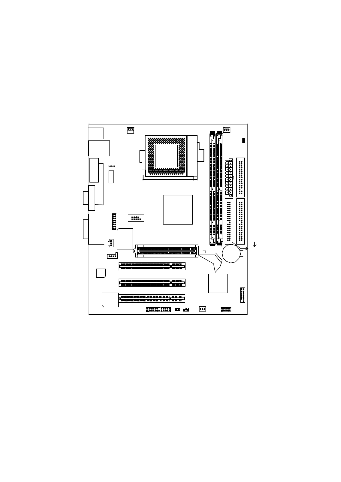
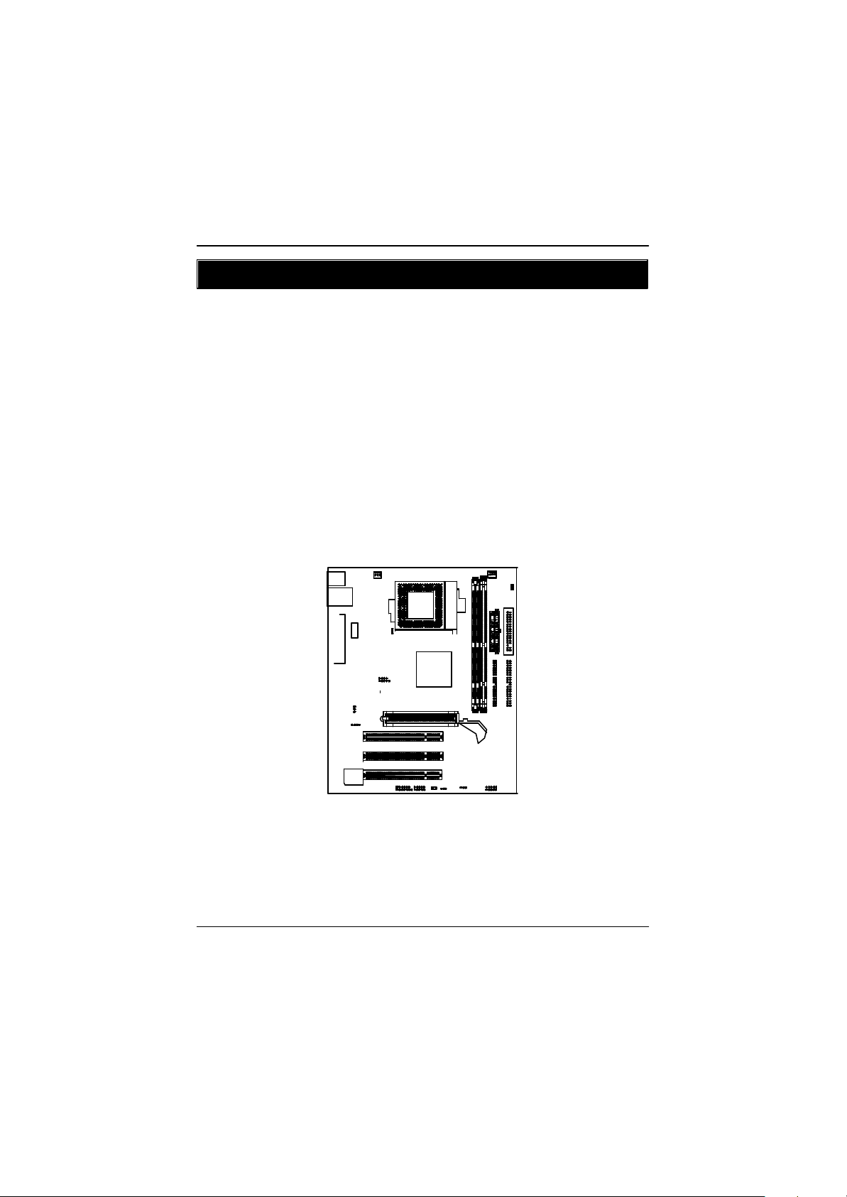
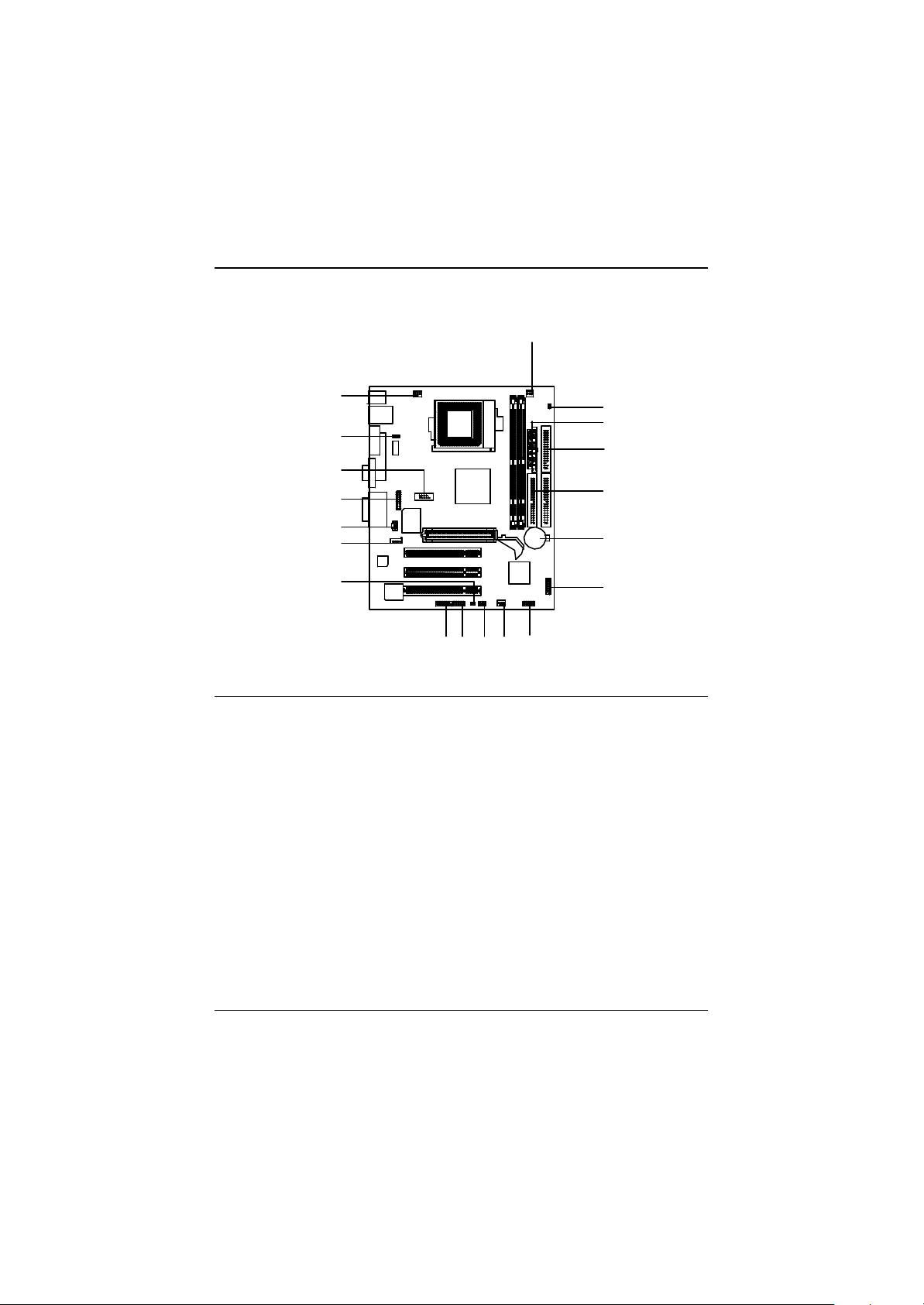
GA-6IEM Series Motherboard Layout
KB_MS
VGA
LINE_OUTMIC_IN
USB
COMA
LINE_IN
AC97
LAN*
LPT1
GAM E
J5
JP34*
Kinnereth*
JP44
IT8712
AGP
J1
COM B
SOCKET 370
GA-6IEM(L)
82815JP41
PCI1
PCI2
DIMM1
ICH2
DIMM2
J2
ATXPWR
BATTERY
LED 2
FLOPPY
F_PANEL
IDE2
IDE1
BIOS
* For GA-6IEML only.
J16
JP13
PCI3
JP22
J12
J14
JP32
8
Page 13
Hardware Installation Process
Chapter 2 Hardware Installation Process
To set up your computer, you must complete the following steps:
Step 1- Install the Central Processing Unit (CPU)
Step 2- Install memory modules
Step 3- Install expansion cards
Step 4- Connect ribbon cables, cabinet wires, and power supply
Step 5- Setup BIOS software
Step 6- Install supporting software tools
9
Page 14
GA-6IEM Series Motherboard
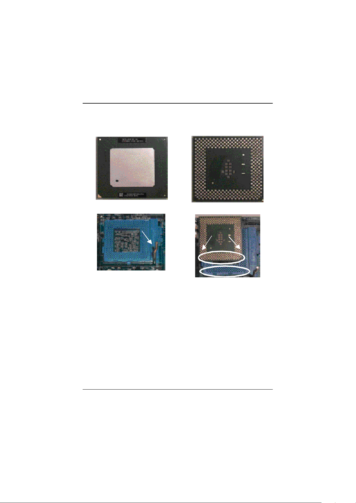
Step1-1: CPU Installation
For example: The newest Pentium III processor (FC-PGA2 package).
CPU Top View CPU Bottom View
Socket Actuation Lever
Pin1 indicator
1. Pull up the CPU socket lever
and up to 90-degree angle.
2. Locate Pin 1 in the socket and look
for a (golden) cut edge on the CPU
upper corner. Then insert the CPU
into the socket.
? Please make sure the CPU type is supported by the motherboard.
? If you do not match the CPU socket Pin 1 and CPU cut edge well, it will cause
improper installation. Please change the insert orientation.
10
Page 15

Step1-2:CPU Heat Sink Installation
Hardware Installation Process
1. Press down the CPU socket
lever and finish CPU installation.
3. Fasten the heatsink supporting-base
onto the CPU socket on the main-
board.
2. Use qualified fan approved by Intel.
4. Make sure the CPU fan is
plugged to the CPU fan connector,
than install complete.
? Please use Intel approved cooling fan.
? We recommend you to apply the thermal paste to provide better heat
conduction between your CPU and heatsink.
? Make sure the CPU fan power cable is plugged in to the CPU fan connector,
this completes the installation.
? Please refer to CPU heat sink user’s manual for more detail installation
procedure.
11
Page 16
GA-6IEM Series Motherboard
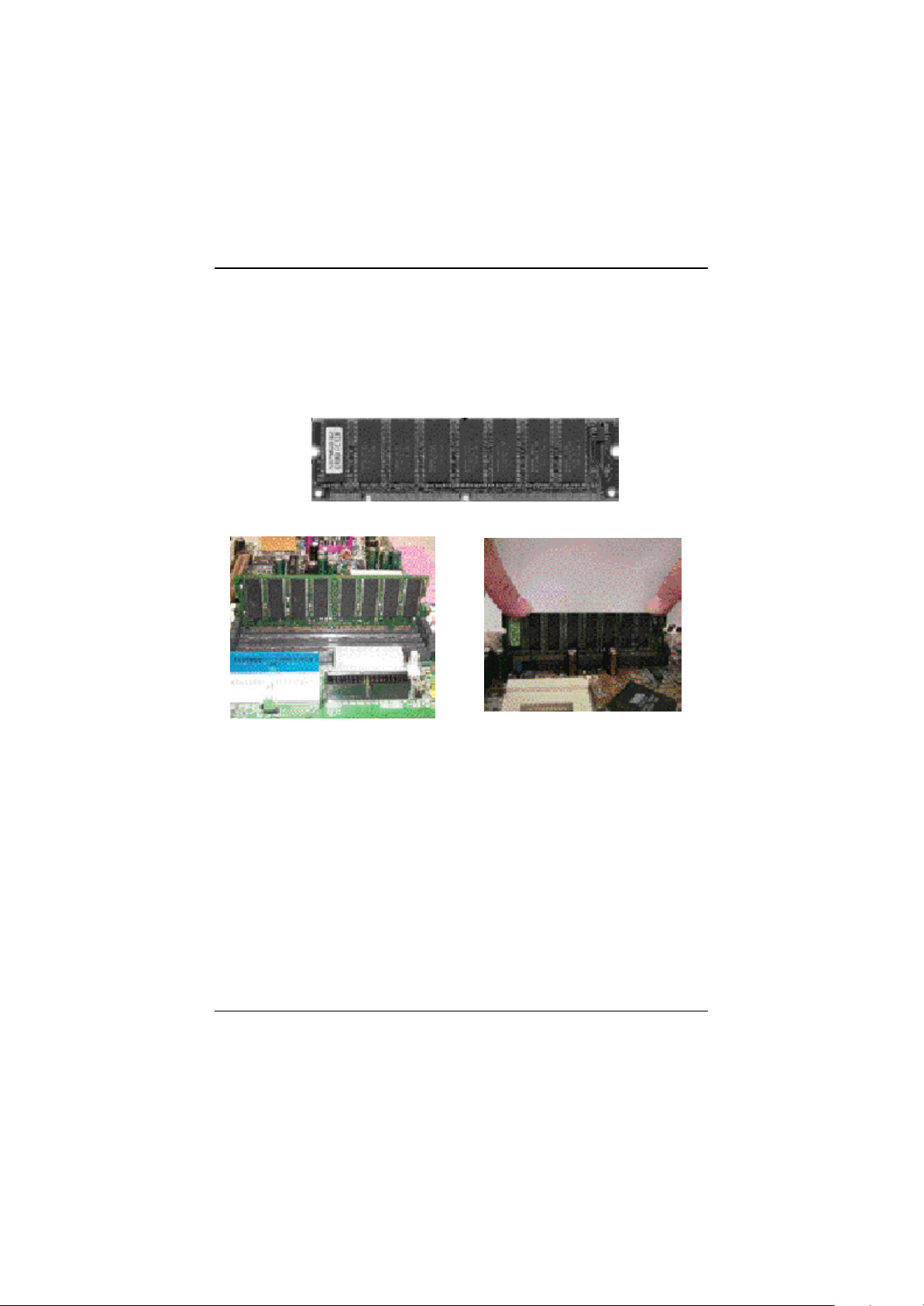
Step 2: Install memory modules
The motherboard has 2 dual in-line memory module (DIMM) sockets support 4 banks. The BIOS will
automatically detects memory type and size. To install the memory module, just push it vertically into the
DIMM Slot .The DIMM module can only fit in one direction due to the two notch. Memory size can vary
between sockets.
SDRAM
1. The DIMM slot has two notch, so the
DIMM memory module can only fit in
one direction.
3. Close the plastic clip at both edges of the DIMM slots to lock the DIMM module.
Reverse the installation steps when you wish to remove the DIMM module.
2. Insert the DIMM memory module
vertically into the DIMM slot. Then
push it down.
? When STR/DIMM LED is ON, do not install/remove SDRAM from socket.
? Please note that the DIMM module can only fit in one direction due to the two
notches. Wrong orientation will cause improper installation. Please change
the insert orientation.
12
Page 17
Hardware Installation Process
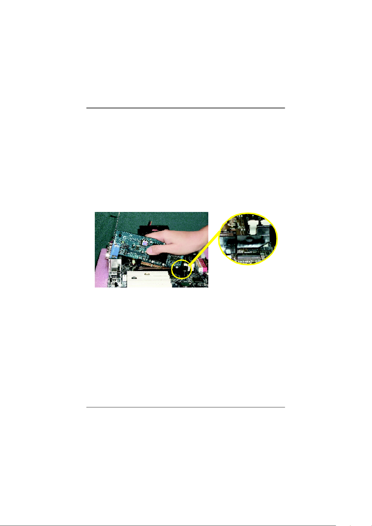
Step 3: Install expansion cards
1. Read the related expansion card’s instruction document before install the expansion card into
the computer.
2. Remove your computer’s chassis cover, screws and slot bracket from the computer.
3. Press the expansion card firmly into expansion slot in motherboard.
4. Be sure the metal contacts on the card are indeed seated in the slot.
5. Replace the screw to secure the slot bracket of the expansion card.
6. Replace your computer’s chassis cover.
7. Power on the computer, if necessary, setup BIOS utility of expansion card from BIOS.
8. Install related driver from the operating system.
when removing the AGP card, please
pull out the retention Module bar.
AGP Card
13
Page 18
GA-6IEM Series Motherboard
Step 4: Connect ribbon cables, cabinet wires, and power
supply
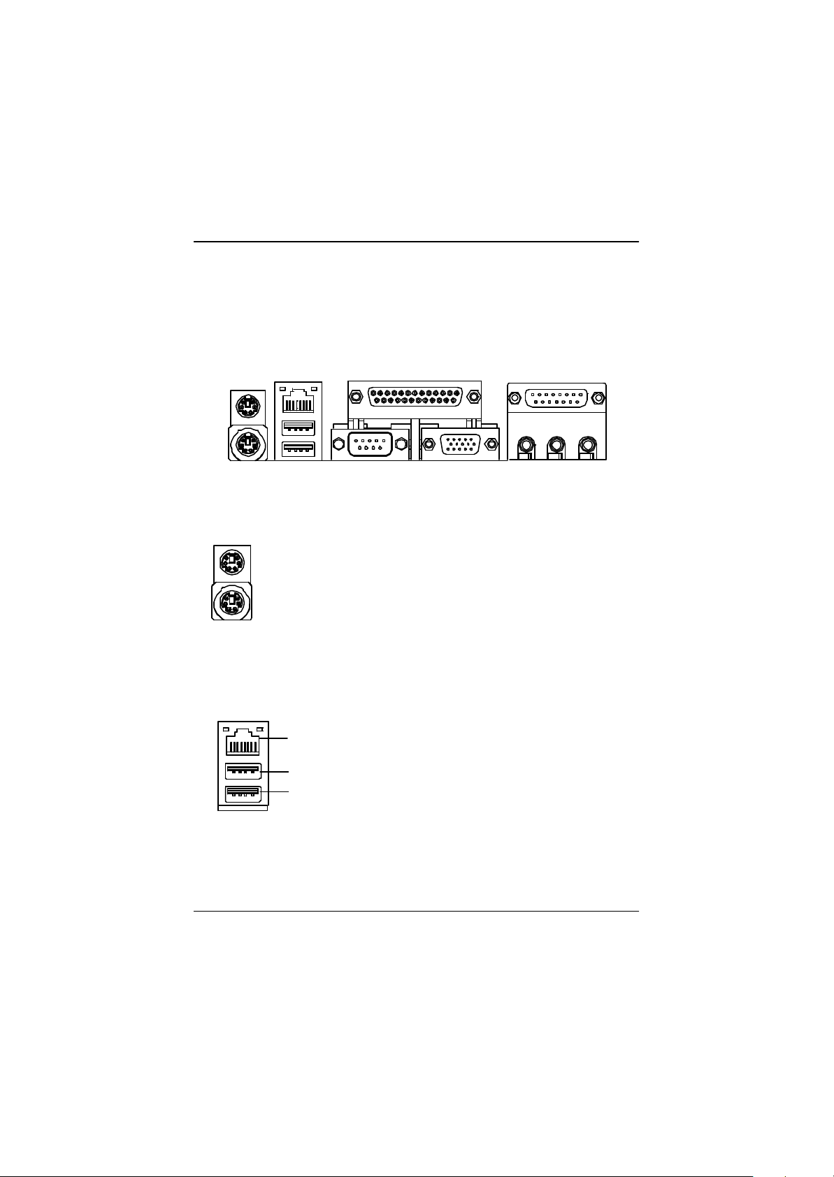
Step4-1:I/O Back Panel Introduction
? ?
?
? PS/2 Keyboard and PS/2 Mouse Connector
PS/2 Mouse Connector
(6 pin Female)
PS/2 Keyboard Connector
(6 pin Female)
? USB & LAN Connector
LAN*
USB 0
USB 1
?This connector supports standard PS/2 keyboard
and PS/2 mouse.
?Before you connect your device(s) into USB
connector(s), please make sure your device(s)
such as USB keyboard,mouse, scanner, zip,
speaker..etc. Have a standard USB interface. Also
make sure your OS (Win 95 with USB supplement,
Win98, Windows 2000, Windows ME, Win NT
with SP 6) supports USB controller. If your OS
does not support USB controller, please contact
OS vendor for possible patch or driver upgrade.
For more information please contact your OS or
device(s) vendors.
?
?
* For GA-6IEML only.
14
Page 19

? Parallel Port , Serial Port and VGA Port (LPT/COMA/VGA)
Parallel Port
(25 pin Female)
COMA VGA
Serial Port
(9 pin Male)
VGA Port
(15 pin Female)
?This connector supports 1 standard COM port
,1 Parallel port and 1 VGA port. Device like
printercan be connected to Parallel port ; mouse
and modem etc can be connected to Serial ports.
Hardware Installation Process
? Game /MIDI Ports
Joystick/ MIDI (15 pin Female)
? Audio Connectors
Line Out
MIC In
Line In
?This connector supports joystick, MIDI keyboard
and other relate audio devices.
? After install onboard audio driver, you may
connect speaker to Line Out jack, micro phone to
MIC In jack. Device like CD-ROM , walkman etc
can be connected to Line-In jack.
15
Page 20
GA-6IEM Series Motherboard
Step4-2: Connectors Introduction
A
A) J2
B) LED 2
C) ATX PWR
D) Floppy
E) IDE/IDE2
F) BATTERY
G) F_PANEL
H) JP32
I) J14
J) J12
S
B
C
R
D
Q
P
O
M
JLNK
HI
E
F
G
K) JP13
L) J16
M) JP22
N) J5
O) JP44
P) JP41
Q) CN10
R) JP34
S) J1
16
Page 21
Hardware Installation Process
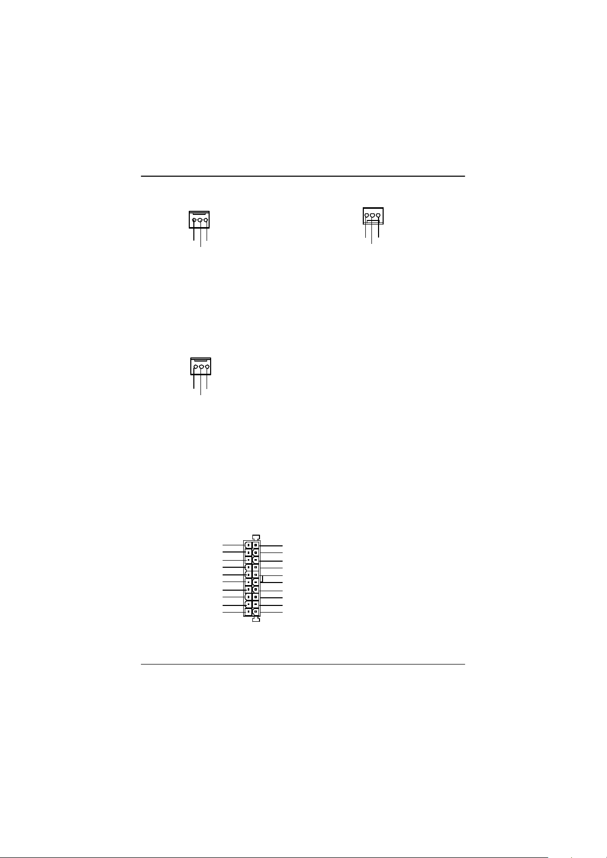
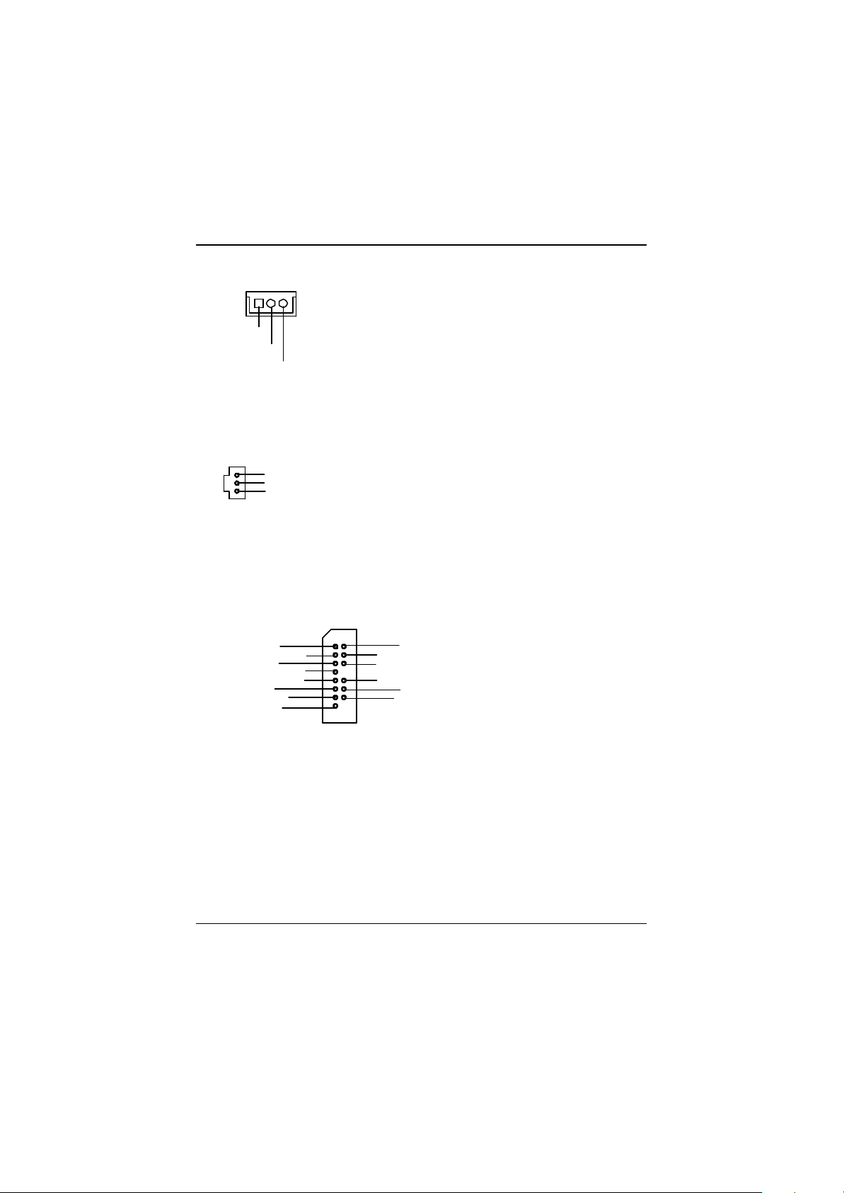
A) J2 (Power_FAN Connector)
1
GND
Sense
+12V/Control
S) J1 (CPU_FAN Connector)
1
GND
Sense
+12V/Control
I) J14 (SYS_FAN Connector)
1
GND
Sense
+12V/Control
? Please note, a proper installation of the CPU
cooleris essential to prevent the CPU from run
ning under abnormal condition or damaged by
overheating.The CPU fan connector supports
Max. current up to 600mA .
C) ATX PWR (ATX Power)
5V SB (Stand by +5V)
+12V
Power Good
GND
VCC
GND
VCC
GND
3.3V
3.3V
? AC power cord should only be connected to
20
VCC
VCC
-5V
GND
GND
GND
PS-ON(Soft On/Off)
GND
-12V
1
3.3V
your power supply unit after ATX power cable
and other related devices are firmly connected
to the mainboard.
17
Page 22
GA-6IEM Series Motherboard
J) J12 (Wake on LAN)
1
+5V SB
GND
Signal
O)JP44 (SPDIF)
1
VCC
SPDIF Out
GND
SPDIF
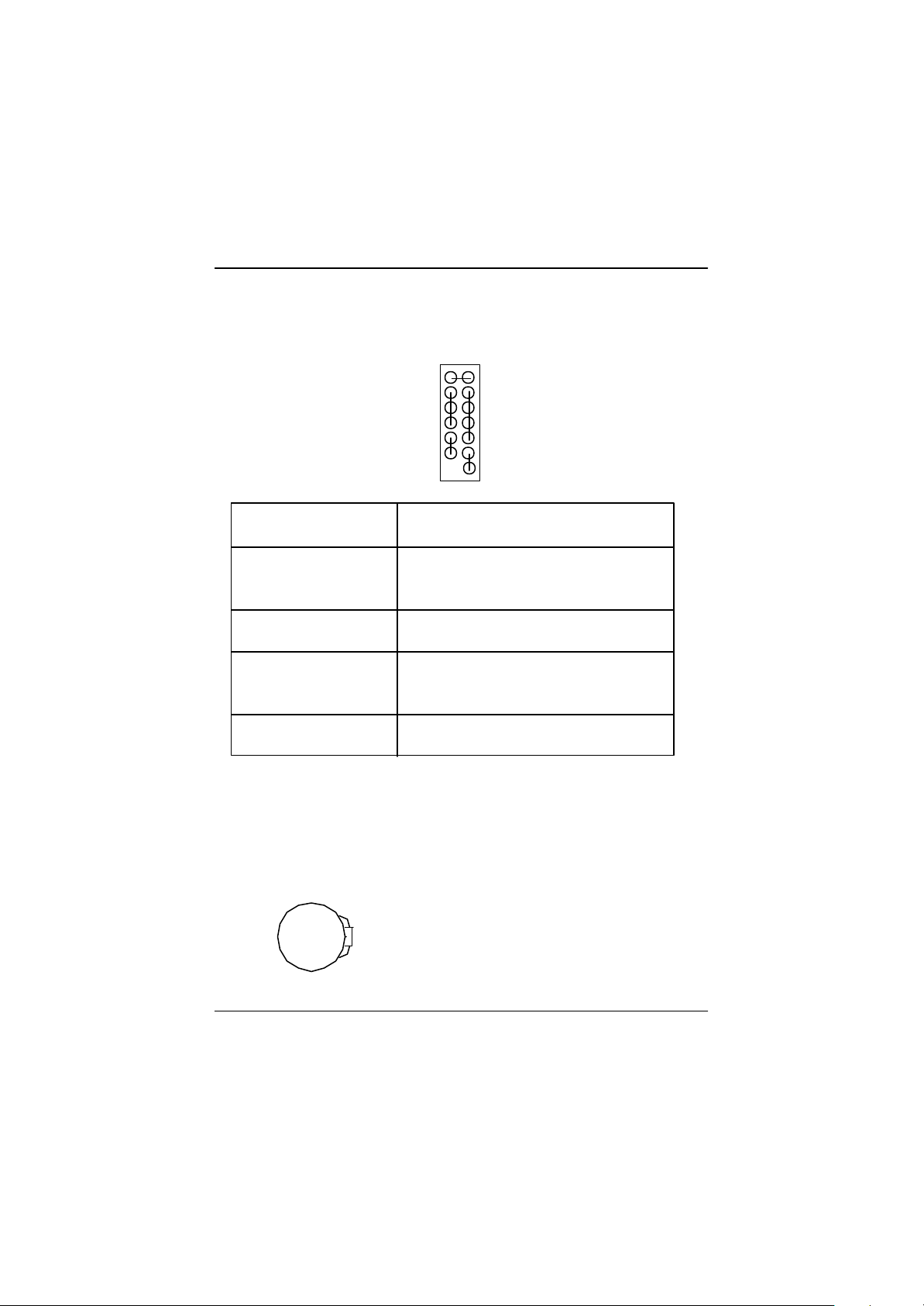
P)JP41 (F_AUDIO Connector)
1
Incase speaker (R)
Front Audio (R)
Front Audio (L)
GND
GND
GND
+12V
MIC
Incase speaker (L)
GND
GND
GND
Front Audio (R)
Front Audio (L)
? The SPDIF output is capable of providing
digital audio to external speakers or com
pressed AC3 data to an external Dolby
Digital Decoder. Use this feature only when
your stereo system has digital input
function.
? If you want to use "Front Audio" connector,
you must move 11-12,13-14 Jumper. In order
to utilize the front audio header, your chassis
must have front audio connector. Also please
make sure the pin assigment on the cable is
the same as the pin assigment on the MB
header. To find out if the chassis you are buy
ing support front audio connector, please
contact your dealer.
18
Page 23
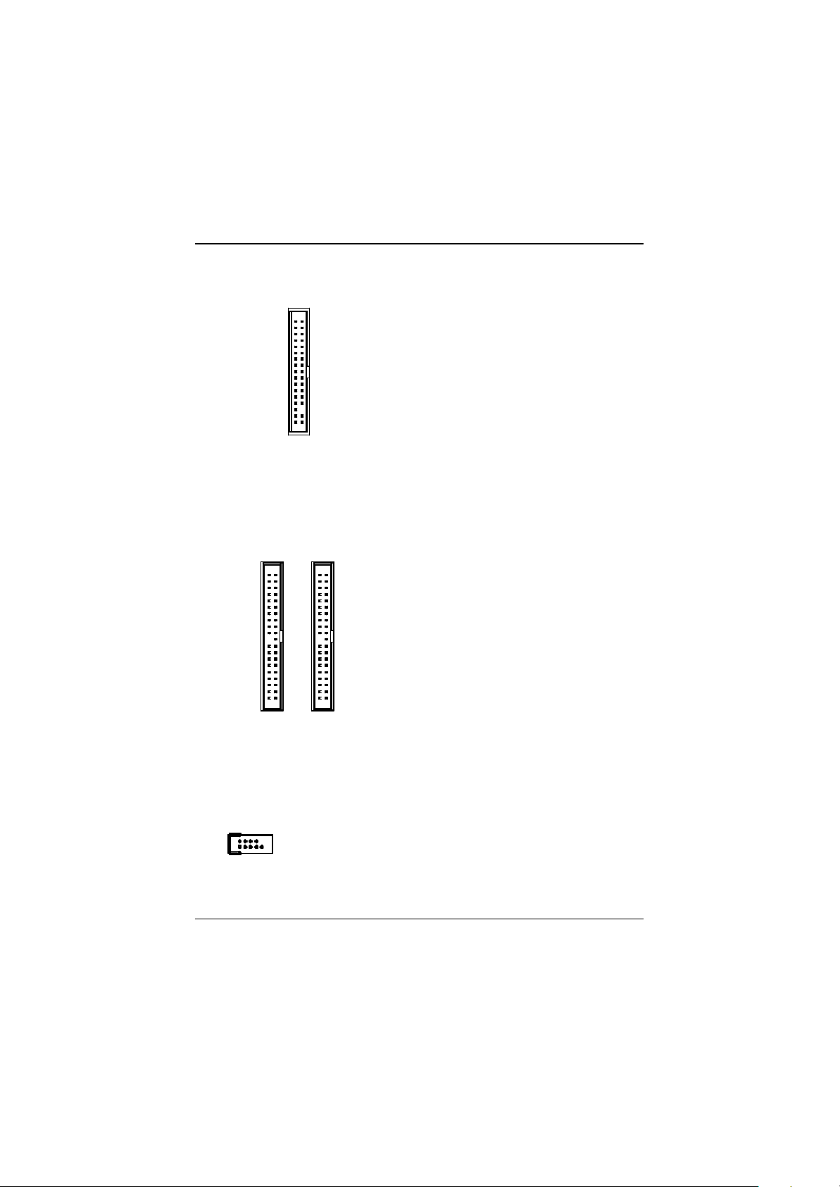
D ) Floppy Connector
1
Floppy
E) IDE1 / IDE2 Connector
Hardware Installation Process
IDE1
Q) CN10 (COM B)
1
1
1
IDE2
19
Page 24
GA-6IEM Series Motherboard
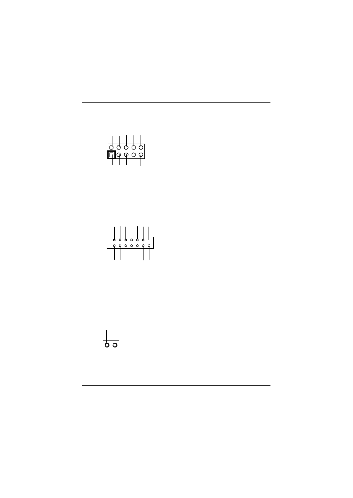
H) JP32 (Front USB Connector)
GND
NC
USB D3+
USB D3-
Power
NC
USB D2-
USB D2+
GND
Power
B) LED 2 (STR/DIMM LED)
1
N) J5 (CD_IN )
? Be careful with the polarity of the front panel
USB connector. Check the pin assignment
while you connect the front panel USB cable.
Please contact your nearest dealer for optional
front panel USB cable.
? Do not remove memory modules while
DIMM LED is on. It might cause short or
other unexpected damages due to the
3.3V stand by voltage. Remove memory
modules only when STR function is
disabled by jumper and AC Power cord is
disconnected.
CD-L
GND
CD-R
1
R) JP34 (Onboard LAN Function)*
1
1-2 close: Enable(Default)
2-3 close: Disable
1
* For GA-6IEML only.
?This MB supports optional LAN chip.If the MB
has optional LAN chip the user can enable the
LAN function by setting the “JP34” to 1-2,
user can disable the optional LAN function by
setting the “JP34” to 2-3. “JP34” will
have any effect if the board does not have
optioal LAN chip.
20
Page 25
Hardware Installation Process
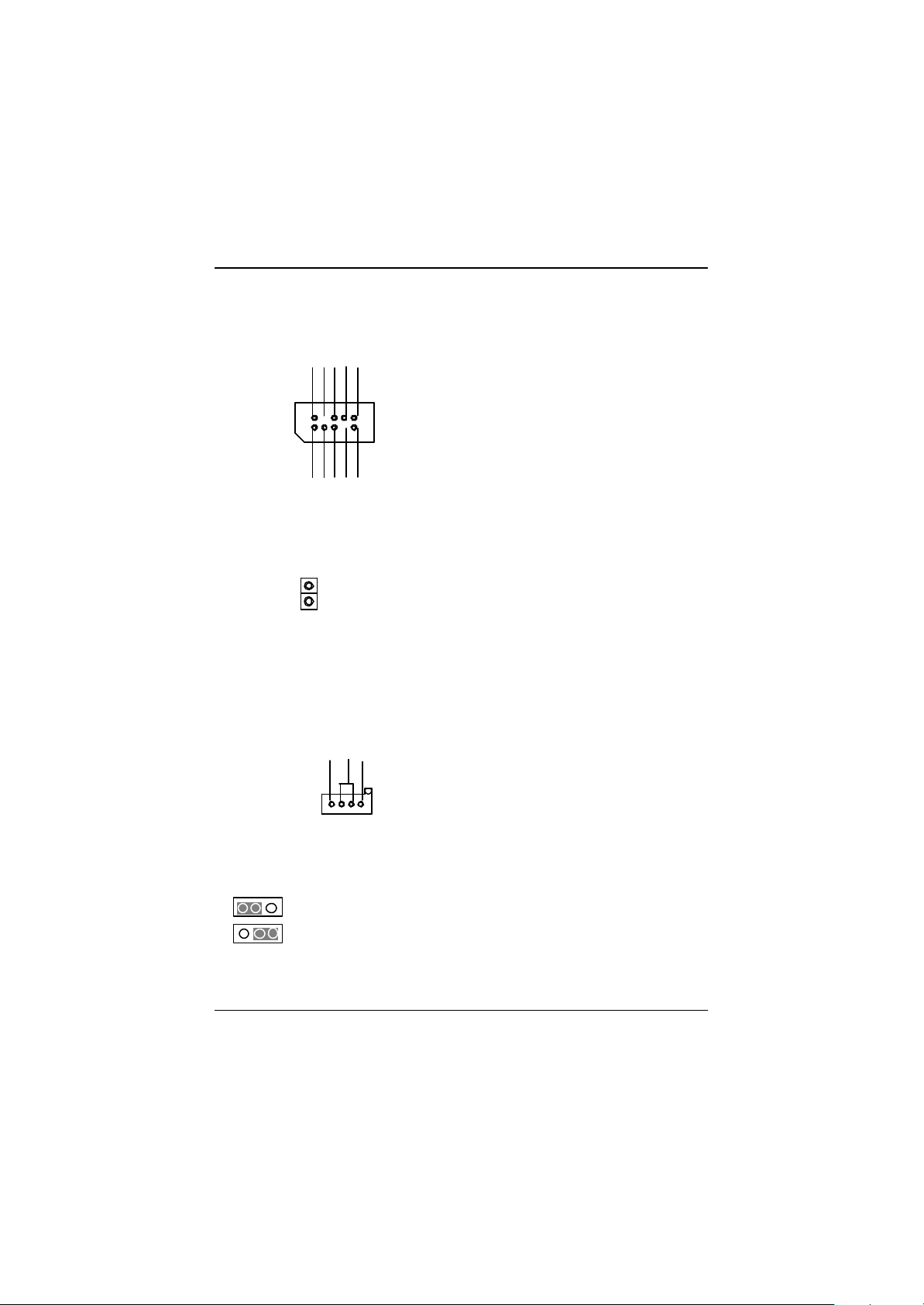
K) JP13 (IR/CIR )
NC
VCC
GND
IRRX
GND
NC
IRTX
CIRRX
1
NC
VCC
L) J16 (Smart Card Reader Header)
NCNCNC
DATA
1
VCC
VCC
Clock
DATA
DATA
NC
DATA
GND
NC
NC
? Make sure the pin 1 on the IR device is
aling with pin one the connector. To
enable the IR/CIR function on the board,
you are required to purchase an option IR/
CIR module. For detail information please
contact your autherized Giga-Byte
distributor.
To use IR function only, please connect IR
module to Pin1 to Pin5.
? This MB supports smart card reader. To enable
smart card reader function an optional smart
card reader box is required. Please contact
your autherized distributor.
M) JP22 (CASE OPEN)
Signal
GND
1
CASE OPEN
? This 2 pin connector allows your system to
enable or disable the system alarm if the sys
tem case begin remove.
21
Page 26
GA-6IEM Series Motherboard
G) F_PANEL (2x7 pins jumper)
1
P-P-P+
1
PW
HD (IDE Hard Disk Active LED) Pin 1: LED anode(+)
Pin 2: LED cathode(-)
SPK (Speaker Connector) Pin 1: VCC(+)
Pin 2- Pin 3: NC
Pin 4: Data(-)
RE (Reset Switch) Open: Normal Operation
Close: Reset Hardware System
P+P-P-(Power LED) Pin 1: LED anode(+)
Pin 2: LED cathode(-)
Pin 3: LED cathode(-)
PW (Soft Power Connector) Open: Normal Operation
Close: Power On/Off
? Please connect the power LED, PC speaker, reset switch and power switch etc of your chassis front
panel to the F_Panel connector according to the pin assignment above.
HD
SPK
1
RE
F) Battery
CAUTION
? Danger of explosion if battery is incorrectly
replaced.
? Replace only with the same or equivalent
+
type recommended by the manufacturer.
? Dispose of used batteries according to the
manufacturer’s instructions.
22
Page 27

BIOS Setup
Chapter 3 BIOS Setup
BIOS Setup is an overview of the BIOS Setup Program. The program that allows users to modify the
basic system configuration. This type of information is stored in battery-backed CMOS RAM so that it
retains the Setup information when the power is turned off.
ENTERING SETUP
Power ON the computer and press <Del> immediately will allow you to enter Setup.
CONTROL KEYS
<?> Move to previous item
<?> Move to next item
<?> Move to the item in the left hand
<?> Move to the item in the right hand
<Esc> Main Menu - Quit and not save changes into CMOS Status Page Setup Menu and
Option Page Setup Menu - Exit current page and return to Main Menu
<+/PgUp> Increase the numeric value or make changes
<-/PgDn> Decrease the numeric value or make changes
<F1> General help, only for Status Page Setup Menu and Option Page Setup Menu
<F2> Reserved
<F3> Reserved
<F4> Reserved
<F5> Restore the previous CMOS value from CMOS, only for Option Page Setup Menu
<F6> Load the default CMOS value from BIOS default table, only for Option Page Setup
Menu
<F7> Load the Setup Defaults
<F8> Reserved
<F9> Reserved
<F10> Save all the CMOS changes, only for Main Menu
23
Page 28

GA-6IEM Series Motherboard
GETTING HELP
Main Menu
The on-line description of the highlighted setup function is displayed at the bottom of the screen.
Status Page Setup Menu / Option Page Setup Menu
Press F1 to pop up a small help window that describes the appropriate keys to use and the possible
selections for the highlighted item. To exit the Help Window press <Esc>.
Q-Flash Uti lity
After power on the computer, pressing <Del> immediately during POST (Power On Self Test) it will
allow you to enter Award BIOS CMOS SETUP, then press <F8> to enter Q-Flash utility.
T he Main Menu (For example: BI O S Ver. :F3d)
Once you enter Award BIOS CMOS Setup Utility, the Main Menu (Figure 1) will appear on the screen.
The Main Menu allows you to select from eight setup functions and two exit choices. Use arrow keys to
select among the items and press <Enter> to accept or enter the sub-menu.
CMOS Setup Utility-Copyright (C) 1984-2001 Award Software
?Standard CMOS Features ?Frequency/Voltage Control
?Advanced BIOS Features Load Fail-Safe Defaults
?Advanced Chipset Features Load Optimized Defaults
?Integrated Peripherals Set Supervisor Password
?Power Management Setup Set User Password
?PnP/PCI Configurations Save & Exit Setup
?PC Health Status Exit Without Saving
ESC:Quit ????:Select Item
F8:Q-Flash F10:Save & Exit Setup
Time, Date, Hard Disk Type...
Figure 1: Main Menu
? Standard CMOS Features
This setup page includes all the items in standard compatible BIOS.
? Advanced BIOS Features
This setup page includes all the items of Award special enhanced features.
24
Page 29

? Advanced Chipset Features
This setup page includes all the items of chipset special features.
? Integrated Peripherals
This setup page includes all onboard peripherals.
? Power Management Setup
This setup page includes all the items of Green function features.
? PnP/PCI Configurations
This setup page includes all the configurations of PCI & PnP ISA resources.
? PC Health Status
This setup page is the System auto detect Temperature, voltage, fan, speed.
? Frequency/Voltage Control
This setup page is control CPU’s clock and frequency ratio.
? Load Fail-Safe Defaults
Fail-Safe Defaults indicates the value of the system parameters which the system would
be in safe configuration.
? Load Optimized Defaults
Optimized Defaults indicates the value of the system parameters which the system would
be in best performance configuration.
? Set Supervis or password
Change, set, or disable password. It allows you to limit access to the system and Setup,
or just to Setup.
? Set User password
Change, set, or disable password. It allows you to limit access to the system.
? Save & Exit Setup
Save CMOS value settings to CMOS and exit setup.
? Exit Without Saving
Abandon all CMOS value changes and exit setup.
BIOS Setup
25
Page 30

GA-6IEM Series Motherboard
Standard CMO S Features
CMOS Setup Utility-Copyright (C) 1984-2001 Award Software
Standard CMOS Features
Date (mm:dd:yy) Mon, Feb 21 2000 Item Help
Time (hh:mm:ss) 22:31:24 Menu Level
?IDE Primary Master [Press Enter None]
?IDE Primary Slave [Press Enter None]
?IDE Secondary Master [Press Enter None]
?IDE Secondary Slave [Press Enter None]
Drive A [1.44M, 3.5 “]
Drive B [None]
Floppy 3 Mode Support [Disabled]
Halt On [All, But Keyboard]
Base Memory 640K
Extended Memory 130048K
Total Memory 131072K
????: Move Enter:Select +/-/PU/PD:Value F10:Save ESC:Exit F1:General Help
F5:Previous Values F6:Fail-Safe Defaults F7:Optimized Defaults
Figure 2: Standard CMOS Features
? Date
The date format is <week>, <month>, <day>, <year>.
?Week The week, from Sun to Sat, determined by the BIOS and is display only
?Month The month, Jan. Through Dec.
?Day The day, from 1 to 31 (or the maximum allowed in the month)
?Year The year, from 1994 through 2079
26
Page 31

BIOS Setup
? Time
The times format in <hour> <minute> <second>. The time is calculated base on the 24-hour
military-time clock. For example, 1 p.m. is 13:00:00.
? IDE Primary Master, Slave / Secondary Master, Slave
The category identifies the types of hard disk from drive C to F that has been installed in the
computer. There are two types: auto type, and manual type. Manual type is user-definable; Auto type
which will automatically detect HDD type.
Note that the specifications of your drive must match with the drive table. The hard disk will not work
properly if you enter improper information for this category.
If you select User Type, related information will be asked to enter to the following items. Enter the
information directly from the keyboard and press <Enter>. Such information should be provided in the
documentation form your hard disk vendor or the system manufacturer.
?CYLS. Number of cylinders
?HEADS Number of heads
?PRECOMP Write precomp
?LANDZONE Landing zone
?SECTORSNumber of sectors
If a hard disk has not been installed select NONE and press <Enter>.
? Drive A / Drive B
The category identifies the types of floppy disk drive A or drive B that has been installed in the
computer.
?None No floppy drive installed
?360K, 5.25 in. 5.25 inch PC-type standard drive; 360K byte capacity.
?1.2M, 5.25 in. 5.25 inch AT-type high-density drive; 1.2M byte capacity
(3.5 inch when 3 Mode is Enabled).
?720K, 3.5 in. 3.5 inch double-sided drive; 720K byte capacity
?1.44M, 3.5 in. 3.5 inch double-sided drive; 1.44M byte capacity.
?2.88M, 3.5 in. 3.5 inch double-sided drive; 2.88M byte capacity.
27
Page 32

GA-6IEM Series Motherboard
? Floppy 3 Mode Support (for Japan Area)
?Disabled Normal Floppy Drive. (Default value)
?Drive A Drive A is 3 mode Floppy Drive.
?Drive B Drive B is 3 mode Floppy Drive.
?Both Drive A & B are 3 mode Floppy Drives.
?Halt on
The category determines whether the computer will stop if an error is detected during power up.
?NO Errors The system boot will not stop for any error that may be detected
and you will be prompted.
?All Errors Whenever the BIOS detects a non-fatal error the system will be stopped.
?All, But Keyboar The system boot will not stop for a keyboard error; it will stop for
all other errors. (Default value)
?All, But Diskette The system boot will not stop for a disk error; it will stop for all
other errors.
?All, But Disk/Key The system boot will not stop for a keyboard or disk error; it will
stop for all other errors.
28
Page 33

??Memory
The category is display-only which is determined by POST (Power On Self Test) of the BIOS.
Base Memory
The POST of the BIOS will determine the amount of base (or conventional) memory
installed in the system.
The value of the base memory is typically 512 K for systems with 512 K memory
installed on the motherboard, or 640 K for systems with 640 K or more memory
installed on the motherboard.
Extended Memory
The BIOS determines how much extended memory is present during the POST.
This is the amount of memory located above 1 MB in the CPU’s memory
address map.
BIOS Setup
29
Page 34

GA-6IEM Series Motherboard
Advanced BIOS Features
CMOS Setup Utility-Copyright (C) 1984-2001 Award Software
Advanced BIOS Features
BIOS Flash Protection [Auto] Item Help
Processor Serial Number [Disabled] Menu Level
First Boot Device [Floppy]
Second Boot Device [HDD-0]
Third Boot Device [CDROM]
Boot Up Floppy Seek [Disabled]
Boot Up Num-Lock [On]
Password Check [Setup]
?Interrupt Mode [APIC]
?MPS Version Control For OS [1.4]
HDD S.M.A.R.T. Capability [Disabled]
????: Move Enter:Select +/-/PU/PD:Value F10:Save ESC:Exit F1:General Help
F5:Previous Values F6:Fail-Safe Defaults F7:Optimized Defaults
Figure 3: Advanced BIOS Features
?These two items will be disable when use VIA Processor(VIA C3, Cyrix
®
MII, Cyrix® III)
/Intel Pentium® !!!, CeleronTM Processor(for specific lots).
? BIOS Flash Protection
This field lets you determine the states that flash BIOS
?Auto BIOS enables flash write access automatically when updating BIOS data/DMI/
ESCD. (Default Value)
?Enabled During POST, DMI/ESCD would not be updated. But flash tools can update BIOS
always.
? Processor Serial Number
?Enabled Pentium III Processor Number Feature.
?Disabled Disable this function.(Default Value)
30
Page 35

BIOS Setup
? First / Second / Third Boot Device
?Floppy Select your boot device priority by Floppy.
?LS120 Select your boot device priority by LS120.
?HDD-0~3 Select your boot device priority by HDD-0~3.
?SCSI Select your boot device priority by SCSI.
?CDROM Select your boot device priority by CDROM.
?ZIP Select your boot device priority by ZIP.
?USB-FDD Select your boot device priority by USB-FDD.
?USB-ZIP Select your boot device priority by USB-ZIP.
?USB-CDROM Select your boot device priority by USB-CDROM.
?USB-HDD Select your boot device priority by USB-HDD.
?LAN Select your boot device priority by LAN.
?Disabled Select your boot device priority by Disabled.
? Boot Up Floppy Seek
During POST, BIOS will determine the floppy disk drive installed is 40 or 80 tracks. 360 K type is
40 tracks 720 K, 1.2 M and 1.44 M are all 80 tracks.
?Enabled BIOS searches for floppy disk drive to determine it is 40 or 80 tracks. Note
that BIOS can not tell from 720 K, 1.2 M or 1.44 M drive type as they are
all 80tracks.
?Disabled BIOS will not search for the type of floppy disk drive by track number. Note
that there will not be any warning message if the drive installed is 360 K.
(Default value)
? Boot Up NumLock
?On Keypad is number keys. (Default value)
?Off Keypad is arrow keys.
31
Page 36

GA-6IEM Series Motherboard
? Passwor d Check
Please refer to the detail on P.60
?System The system can not boot and can not access to Setup page will be denied
if the correct password is not entered at the prompt.
?Setup The system will boot, but access to Setup will be denied if the correct
password is not entered at the prompt. (Default value)
?Interrupt Mode
?APIC Through IOAPIC generate more IRQ for system use.(Default value)
?PIC Use AT stantard IRQ controlles to generate IRQ.
When you already have I OAPIC enable system and want to upgrade the system please note, since
running an IOAPIC enabled OS (like Windows NT,Windows 2000, Windows XP...) system with none
IOAPIC HW support will cause the system to hang. Following are some situations users might run into:
1.An IOAPI C enabled OS and change the BIOS setting from IOAPIC to PIC, this will cause your
system to hang.
2.An IOAPIC enabled OS and change a processor from IOAPIC supported to none IOAPIC support
(like VIA C3, Cyrix
®
MII, Cyrix® III), and some I ntel Pentium
number), this will disable the IOAPIC in the BIOS and cause the system to hang.
When above situation happened you will have to reinstall the OS.
®
!!!, CeleronTM Processor(certain lot
? MPS Versi on Control For OS
(Support Multi Processor Specification revision 1.4)
?1.4 Support MPS Version 1.4 . (Default Value)
?1.1 Support MPS Version 1.1.
?HDD S.M.A.R.T. Capability
?Enabled Enable HDD S.M.A.R.T. Capability.
?Disabled Disable HDD S.M.A.R.T. Capability. (Default value)
32
Page 37

BIOS Setup
Advanced Chipset Features
We would not suggest you change the chipset default setting unless you really need it.
CMOS Setup Utility-Copyright (C) 1984-2001 Award Software
Advanced Chipset Features
Top Performance [Disabled] Item Help
SDRAM Timing Control [Auto] Menu Level
X SDRAM CAS Latency Time 3
X SDRAM Cycle Time Tras/Trc 7/9
X SDRAM RAS-to-CAS Delay 3
X SDRAM RAS Precharge Time 3
Delayed Transaction [Enabled]
AGP Graphics Aperture Size [64MB]
AGP Device 4X Support [Enabled]
On-Chip Video windows Size [64MB]
?Buffer Strength Parameter [Press Enter]
????: Move Enter:Select +/-/PU/PD:Value F10:Save ESC:Exit F1:General Help
F5:Previous Values F6:Fail-Safe Defaults F7:Optimized Defaults
Figure 4: Advanced Chipset Features
33
Page 38

GA-6IEM Series Motherboard
CMOS Setup Utility-Copyright (C) 1984-2001 Award Software
Advanced Chipset Features
Buffer Strength Control Auto Item Help
X SWE#, SCAS#, SRAS, SMAA, SBS Default Menu Level
X SMD[63:0], SDQM[7:0] Default
X SMAA#[7:4] (Rows 0/1) Default
X SMAB#[7:4] (Rows 2/3) Default
X SMAC#[7:4] (Rows 4/5) Default
X SCS[0]# (Row 0) Default
X SCS[1]# (Row 1) Default
X SCS[2]# (Row 2) Default
X SCS[3]# (Row 3) Default
X SCS[4]# (Row 4) Default
X SCS[5]# (Row 5) Default
X SCKE[0]# (Row 0) Default
X SCKE[1]# (Row 1) Default
X SCKE[2]# (Row 2) Default
X SCKE[3]# (Row 3) Default
X SCKE[4]# (Row 4) Default
X SCKE[5]# (Row 5) Default
????: Move Enter:Select +/-/PU/PD:Value F10:Save ESC:Exit F1:General Help
F5:Previous Values F6:Fail-Safe Defaults F7:Optimized Defaults
Figure 4-1: Advanced Chipset Features
? Top Performance
If you wish to maximize the performance of your system, set "Top Performance" as "Enabled".
?Disabled Disable this function. (Default Value)
?Enabled Enable Top Performance function.
? SDRAM Timing Control
? Auto Set SDRAM Timing Control to Auto. (Default value)
?Manual Set SDRAM Timing Control to Manual.
34
Page 39

? SDRAM CAS Latency Time
?3 Set SDRAM CAS Latency to 3 SCLKS.(Default Value)
?2 Set SDRAM CAS Latency to 2 SCLKS.
? SDRAM Cycle Time Tras/Trc
?7/9 Set SDRAM Tras/Trc Cycle time to 7/9 SCLKs. (Default value)
?5/7 Set SDRAM Tras/Trc Cycle time to 5/7 SCLKs.
? SDRAM RAS-to-CAS Delay
?3 Set SDRAM RAS-to-CAS delay 3 SCLKs. (Default value)
?2 Set SDRAM RAS-to-CAS delay 2 SCLKs.
? SDRAM RAS Precharge Time
?3 Set SDRAM RAS Precharge Time to 3. (Default value)
?2 Set SDRAM RAS Precharge Time to 2.
? Delayed Transaction
?Disabled Normal operation.
?Enabled For slow speed ISA device in system. (Default value)
BIOS Setup
? AGP Graphics Aperture Size
?32MB AGP Graphics Aperture Size is 32MB.
?64MB AGP Graphics Aperture Size is 64MB. (Default Value)
? AGP Device 4X Support
?Enabled Enable support AGP Device 4X function. (Default Value)
?Disabled Disable this function.
35
Page 40

GA-6IEM Series Motherboard
? Onchip Video Windows Size
?Disabled Disabled this function.
?64MB Set onchip video size is 64MB. (Default Value)
? Buffer Strength Control
?Auto Set SDRAM Buffer Strength to Auto. (Default value)
?Manual Set SDRAM Buffer Strength to Manual.
? SWE#, SCAS#, SRAS#, SMAA, SBS
?Default Set SWE#, SCAS#, SRAS#, SMAA, SBS to Default. (Default value)
?1.7x Set SWE#, SCAS#, SRAS#, SMAA, SBS to 1.7x.
?0.7x Set SWE#, SCAS#, SRAS#, SMAA, SBS to 0.7x.
?1.0x Set SWE#, SCAS#, SRAS#, SMAA, SBS to 1.0x.
? SMD[63:0], SDQM[7:0]
?Default Set SMD[63:0], SDQM[7:0] to Default. (Default value)
?1.7x Set SMD[63:0], SDQM[7:0] to 1.7x.
?0.7x Set SMD[63:0], SDQM[7:0] to 0.7x.
?1.0x Set SMD[63:0], SDQM[7:0] to 1.0x.
? SMAA#[7:4] (Rows 0/1)
?Default Set SMAA#[7:4] (Rows 0/1) to Default. (Default value)
?2.7x Set SMAA#[7:4] (Rows 0/1) to 2.7x.
?1.7x Set SMAA#[7:4] (Rows 0/1) to 1.7x.
?1.0x Set SMAA#[7:4] (Rows 0/1) to 1.0x.
36
Page 41

? SMAB#[7:4] (Rows 2/3)
?Default Set SMAB#[7:4] (Rows 2/3) to Default. (Default value)
?2.7x Set SMAB#[7:4] (Rows 2/3) to 2.7x.
?1.7x Set SMAB#[7:4] (Rows 2/3) to 1.7x.
?1.0x Set SMAB#[7:4] (Rows 2/3) to 1.0x.
? SMAC#[7:4] (Rows 4/5)
?Default Set SMAC#[7:4] (Rows 4/5) to Default. (Default value)
?2.7x Set SMAC#[7:4] (Rows 4/5) to 2.7x.
?1.7x Set SMAC#[7:4] (Rows 4/5) to 1.7x.
?1.0x Set SMAC#[7:4] (Rows 4/5) to 1.0x.
? SCS[0]# (Row 0)
?Default Set SCS[0]# (Row 0) to Default. (Default value)
?1.7x Set SCS[0]# (Row 0) to 1.7x.
?1.0x Set SCS[0]# (Row 0) to 1.0x.
? SCS[1]# (Row 1)
?Default Set SCS[1]# (Row 1) to Default. (Default value)
?1.7x Set SCS[1]# (Row 1) to 1.7x.
?1.0x Set SCS[1]# (Row 1) to 1.0x.
BIOS Setup
? SCS[2]# (Row 2)
?Default Set SCS[2]# (Row 2) to Default. (Default value)
?1.7x Set SCS[2]# (Row 2) to 1.7x.
?1.0x Set SCS[2]# (Row 2) to 1.0x.
37
Page 42

GA-6IEM Series Motherboard
? SCS[3]# (Row 3)
?Default Set SCS[3]# (Row 3) to Default. (Default value)
?1.7x Set SCS[3]# (Row 3) to 1.7x.
?1.0x Set SCS[3]# (Row 3) to 1.0x.
? SCS[4]# (Row 4)
?Default Set SCS[4]# (Row 4) to Default. (Default value)
?1.7x Set SCS[4]# (Row 4) to 1.7x.
?1.0x Set SCS[4]# (Row 4) to 1.0x.
? SCS[5]# (Row 5)
?Default Set SCS[5]# (Row 5) to Default. (Default value)
?1.7x Set SCS[5]# (Row 5) to 1.7x.
?1.0x Set SCS[5]# (Row 5) to 1.0x.
? SCKE[0]# (Row 0)
?Default Set SCKE[0]# (Row 0) to Default. (Default value)
?2.7x Set SCKE[0]# (Row 0) to 2.7x.
?1.7x Set SCKE[0]# (Row 0) to 1.7x.
? SCKE[1]# (Row 1)
?Default Set SCKE[1]# (Row 1) to Default. (Default value)
?2.7x Set SCKE[1]# (Row 1) to 2.7x.
?1.7x Set SCKE[1]# (Row 1) to 1.7x.
? SCKE[2]# (Row 2)
?Default Set SCKE[2]# (Row 2) to Default. (Default value)
?2.7x Set SCKE[2]# (Row 2) to 2.7x.
?1.7x Set SCKE[2]# (Row 2) to 1.7x.
38
Page 43

? SCKE[3]# (Row 3)
?Default Set SCKE[3]# (Row 3) to Default. (Default value)
?2.7x Set SCKE[3]# (Row 3) to 2.7x.
?1.7x Set SCKE[3]# (Row 3) to 1.7x.
? SCKE[4]# (Row 4)
?Default Set SCKE[4]# (Row 4) to Default. (Default value)
?2.7x Set SCKE[4]# (Row 4) to 2.7x.
?1.7x Set SCKE[4]# (Row 4) to 1.7x.
? SCKE[5]# (Row 5)
?Default Set SCKE[5]# (Row 5) to Default. (Default value)
?2.7x Set SCKE[5]# (Row 5) to 2.7x.
?1.7x Set SCKE[5]# (Row 5) to 1.7x.
BIOS Setup
39
Page 44

GA-6IEM Series Motherboard
Integrated Peripherals
CMOS Setup Utility-Copyright (C) 1984-2001 Award Software
Integrated Peripherals
On-Chip Primary PCI IDE [Enabled] Item Help
On-Chip Secondary PCI IDE [Enabled] Menu Level
IDE Primary Master PIO [Auto]
IDE Primary Slave PIO [Auto]
IDE Secondary Master PIO [Auto]
IDE Secondary Slave PIO [Auto]
IDE Primary Master UDMA [Auto]
IDE Primary Slave UDMA [Auto]
IDE Secondary Master UDMA [Auto]
IDE Secondary Slave UDMA [Auto]
IDE1 Conductor Cable [Auto]
IDE2 Conductor Cable [Auto]
USB Controller [Enabled]
USB Keyboard Support [Disabled]
USB Mouse Support [Disabled]
Init Display First [PCI]
AC97 Audio [Auto]
AC97 Modem [Auto]
Power On By Mouse [Disabled]
Power On By Keyboard [Disabled]
X KB Power ON Password Enter
Onboard FDC Controller [Enabled]
Onboard Serial Port 1 [3F8/IRQ4]
Onboard Serial Port 2 [2F8/IRQ3]
UART Mode Select [Normal]
????: Move Enter:Select +/-/PU/PD:Value F10:Save ESC:Exit F1:General Help
F5:Previous Values F6:Fail-Safe Defaults F7:Optimized Defaults
Figure 5: Integrated Peripherals
40
Page 45

BIOS Setup
CMOS Setup Utility-Copyright (C) 1984-2001 Award Software
Integrated Peripherals
?UR2 Duplex Mode Half Item Help
Onboard Parallel Port [378/IRQ7] Menu Level
Parallel Port Mode [SPP]
X ECP Mode Use DMA 3
AC BACK Function [Soft-Off]
Game Port Address [201]
Midi Port Address [330]
Midi Port IRQ [10]
CIR Port Address [Disabled]
?CIR Port IRQ 11
????: Move Enter:Select +/-/PU/PD:Value F10:Save ESC:Exit F1:General Help
F5:Previous Values F6:Fail-Safe Defaults F7:Optimized Defaults
Figure 5-1: Integrated Peripherals
? This item will be available when "UART Mode Select" is set to IrDA or ASKIR.
?This item will be available when "CIR Port Address" is set to 310 or 320.
? On-Chip Primary PCI IDE
?Enabled Enable onboard 1st channel IDE port. (Default value)
?Disabled Disable onboard 1st channel IDE port.
? On-Chip Secondary PCI IDE
?Enabled Enable onboard 2nd channel IDE port. (Default value)
?Disabled Disable onboard 2nd channel IDE port.
? IDE Primary Master PIO (for onboard IDE 1st channel)
?Auto BIOS will automatically detect the IDE HDD Accessing mode. (Default value)
?Mode0~4 Manually set the IDE Accessing mode.
41
Page 46

GA-6IEM Series Motherboard
? IDE Primary Slave PIO (for onboard IDE 1st channel)
?Auto BIOS will automatically detect the IDE HDD Accessing mode.(Default value)
?Mode0~4 Manually set the IDE Accessing mode.
? IDE Secondary Master PIO (for onboard IDE 2nd channel)
?Auto BIOS will automatically detect the IDE HDD Accessing mode.(Default value)
?Mode0~4 Manually set the IDE Accessing mode.
? IDE Secondary Slave PIO (for onboard IDE 2nd channel)
?Auto BIOS will automatically detect the IDE HDD Accessing mode.(Default value)
?Mode0~4 Manually set the IDE Accessing mode.
? IDE Primary Master UDMA
?Auto BIOS will automatically detect the IDE HDD Accessing mode.(Default value)
?Disabled Disable UDMA function.
? IDE Primary Slave UDMA
?Auto BIOS will automatically detect the IDE HDD Accessing mode.(Default value)
?Disabled Disable UDMA function.
? IDE Secondary Master UDMA
?Auto BIOS will automatically detect the IDE HDD Accessing mode.(Default value)
?Disabled Disable UDMA function.
? IDE Secondar y Slave UDMA
?Auto BIOS will automatically detect the IDE HDD Accessing mode.(Default value)
?Disabled Disable UDMA function.
42
Page 47

BIOS Setup
? IDE1 Conductor Cable
?Auto Will be automatically detected by BIOS. (Default Value)
?ATA66/100 Set IDE1 Conductor Cable to ATA66/100 (Please make sure your IDE device
and cable is compatible with ATA66/100).
?ATA33 Set IDE1 Conductor Cable to ATA33 (Please make sure your IDE device and
cable is compatible with ATA33).
? IDE2 Conductor Cable
?Auto Will be automatically detected by BIOS. (Default Value)
?ATA66/100 Set IDE2 Conductor Cable to ATA66/100 (Please make sure your IDE device
and cable is compatible with ATA66/100).
?ATA33 Set IDE2 Conductor Cable to ATA33 (Please make sure your IDE device and
cable is compatible with ATA33).
? USB Controller
?Enabled Enable USB Controller. (Default value)
?Disabled Disable USB Controller.
? USB Keyboard Support
?Enabled Enable USB Keyboard Support.
?Disabled Disable USB Keyboard Support. (Default value)
? USB Mouse Support
?Enabled Enable USB Mouse Support.
?Disabled Disable USB Mouse Support. (Default value)
? Init Display First
?PCI Set Init Display First to PCI. (Default value)
?Onboard/AGP Set Init Display First to Onboard / AGP.
43
Page 48

GA-6IEM Series Motherboard
? AC97 Audio
?Auto Enable onboard AC'97 audio function. (Default Value)
?Disabled Disable this function.
? AC97 Modem
?Auto BIOS will search MC97 Codec (AMR Modem Card). If found, MC97 function
will be enabled. If no MC97 Codec found, MC97 function will be disabled.
(Default Value)
?Disabled Disable this function.
? Power On By Mouse
?Mouse Click Double click on PS/2 mouse left button.
?Disabled Disable this function. (Default value)
? Power On By Keyboard
?Password Enter from 1 to 5 characters to set the Keyboard Power On Password.
?Disabled Disable this function. (Default value)
?Keyboard 98 If your keyboard have "POWER Key" button, you can press the key to power on
your system.
? KB Power ON Password
?Enter Input password (from 1 to 5 characters) and press Enter to set the Keyboard
Power On Password.
? Onboard FDC Controller
?Enabled Enable onboard FDC port. (Default value)
?Disabled Disable onboard FDC port.
44
Page 49

? Onboard Serial Port 1
?Auto BIOS will automatically setup the port 1 address.
?3F8/IRQ4 Enable onboard Serial port 1 and address is 3F8. (Default value)
?2F8/IRQ3 Enable onboard Serial port 1 and address is 2F8.
?3E8/IRQ4 Enable onboard Serial port 1 and address is 3E8.
?2E8/IRQ3 Enable onboard Serial port 1 and address is 2E8.
?Disabled Disable onboard Serial port 1.
? Onboard Serial Port 2
?Auto BIOS will automatically setup the port 2 address.
?3F8/IRQ4 Enable onboard Serial port 2 and address is 3F8. (Default value)
?2F8/IRQ3 Enable onboard Serial port 2 and address is 2F8.
?3E8/IRQ4 Enable onboard Serial port 2 and address is 3E8.
?2E8/IRQ3 Enable onboard Serial port 2 and address is 2E8.
?Disabled Disable onboard Serial port 2.
? UART Mode Select
(This item allows you to determine which Infra Red(IR) function of Onboard I/O chip)
?ASKIR Set onboard I/O chip UART to ASKIR Mode.
?IrDA Set onboard I/O chip UART to IrDA Mode.
?SCR Set onboard I/O chip UART to SCR Mode.
?Normal Set onboard I/O chip UART to Normal Mode. (Default Value)
BIOS Setup
? UR2 Duplex Mode
?Half IR Function Duplex Half. (Default Value)
?Full IR Function Duplex Full.
45
Page 50

GA-6IEM Series Motherboard
? Onboard Parallel port
?378/IRQ7 Enable onboard LPT port and address is 378/IRQ7. (Default Value)
?278/IRQ5 Enable onboard LPT port and address is 278/IRQ5.
?Disabled Disable onboard LPT port.
?3BC/IRQ7 Enable onboard LPT port and address is 3BC/IRQ7.
?Parallel Port Mode
?SPP Using Parallel port as Standard Parallel Port. (Default Value)
?EPP Using Parallel port as Enhanced Parallel Port.
?ECP Using Parallel port as Extended Capabilities Port.
?ECP+EPP Using Parallel port as ECP & EPP mode.
?ECP Mode Use DMA
?3 Set ECP Mode Use DMA to 3. (Default Value)
?1 Set ECP Mode Use DMA to 1.
?AC Back Function
?Memory System power on depends on the status before AC lost.
?Soft-Off Always in Off state when AC back. (Default value)
?Full-On Always power on the system when AC back.
?Game Port Address
?Disabled Disabled this function.
?201 Set Game Port Address to 201. (Default Value)
?209 Set Game Port Address to 209.
?Midi Port Address
?Disabled Disabled this function.
?290 Set Midi Port Address to 290.
?300 Set Midi Port Address to 300.
?330 Set Midi Port Address to 300.(Default Value)
46
Page 51

?Midi Port IRQ
?5 Set 5 for Midi Port IRQ.
?10 Set 11 for Midi Port IRQ. (Default Value)
?CIR Port Address
?Disabled Disable this function. (Default Value)
?310 Set CIR Port Address to 310.
?320 Set CIR Port Address to 320.
?CIR Port IRQ
?5 Set 5 for CIR Port IRQ.
?11 Set 11 for CIR Port IRQ. (Default Value)
BIOS Setup
47
Page 52

GA-6IEM Series Motherboard
Power Management Setup
CMOS Setup Utility-Copyright (C) 1984-2001 Award Software
Power Management Setup
ACPI Suspend Type [S1(POS)]
USB Device Wake-Up From S3 [Disabled]
X Power Management [User Define] Menu Level
Video Off Method [DPMS]
Video Off In Suspend [Yes]
Suspend Type [Stop Grant]
MODEM Use IRQ [NA]
Suspend Mode [Disabled]
HDD Power Down [Disabled]
Soft-Off by PWR-BTTN [Instant-off]
PME Event Wake Up [Enabled]
ModemRingOn/WakeOnLan [Enabled]
Resume by Alarm [Disabled]
X Date(of Month) Alarm Everyday
X Time(hh:mm:ss) Alarm 0 0 0
** Reload Global Timer Events **
Primary IDE 0 [Disabled]
Primary IDE 1 [Disabled]
Secondary IDE 0 [Disabled]
Secondary IDE 1 [Disabled]
FDD,COM,LPT Port [Disabled]
PCI PIRQ[A-D]# [Disabled]
????: Move Enter:Select +/-/PU/PD:Value F10:Save ESC:Exit F1:General Help
F5:Previous Values F6:Fail-Safe Defaults F7:Optimized Defaults
Figure 6: Power Management Setup
48
Page 53

BIOS Setup
? ACPI Suspend Type
?S1(POS) Set ACPI Suspend Type to S1/POS (Power On Suspend). (Default value)
?S3(STR) Set ACPI Suspend Type to S3/STR (Suspend To RAM).
? USB Device Wake-Up Fr om S3
?Enabled Enable USB Device Wakeup From S3.
?Disabled Disable USB Device Wakeup From S3. (Default value)
? Power Management
?User Define For configuring our own power management features (Default Value)
?Min Saving Disable Green & software APM function.
?Max Saving Enable Green & software APM function.
? Video off Method
?V/H SYNC+Blank BIOS will turn off V/H-SYNC when gets into Green mode for Green monitor
power saving.
?Blank Screen BIOS will only black monitor when gets into Green mode.
?DPMS BIOS will use DPMS Standard to control VGA card. (The Green type VGA
card will turn off V/H-SYNC automatically.)(Default value)
? Video Off In Suspend
?Yes Enable Video Off In Suspend function. (Default value)
?No Disable this function.
? Suspend Type
?Stop Grant Set Suspend Type to stop grant. (Default value)
?PwrOn Suspend Set Suspend Type to Power on Suspend.
49
Page 54

GA-6IEM Series Motherboard
? MODEM Use IRQ
?N/A Set MODEM Use IRQ to NA.(Default value)
?3 Set MODEM Use IRQ to 3.
?4 Set MODEM Use IRQ to 4.
?5 Set MODEM Use IRQ to 5.
?7 Set MODEM Use IRQ to 7.
?9 Set MODEM Use IRQ to 9.
?10 Set MODEM Use IRQ to 10.
?11 Set MODEM Use IRQ to 11.
? Suspend Mode
?Disabled Disable Suspend Mode. (Default value)
?1 min - 1 Hour Setup the timer to enter Suspend Mode.
? HDD Power Down
?Disabled Disable HDD Power Down mode function. (Default value)
?1-15 mins. Enable HDD Power Down mode between 1 to 15 mins.
? Soft-off by PWR-BTTN
?Instant-off Press power button then Power off instantly. (Default value)
?Delay 4 Sec. Press power button 4 sec to Power off. Enter suspend if button is pressed less
than 4 sec.
? PME Event Wake UP
?Disabled Disable this function.
?Enabled Enable PME Event Wake up. (Default Value)
50
Page 55

? Modem Ring On/Wake On LAN
?Disabled Disable Modem Ring on/wake on Lan function.
?Enabled Enable Modem Ring on/wake on Lan. (Default Value)
? Resume by Alarm
You can set "Resume by Alarm" item to enabled and key in Data/time to power on system.
?Disabled Disable this function. (Default Value)
?Enabled Enable alarm function to POWER ON system.
If RTC Alarm Lead To Power On is Enabled.
Date ( of Month) Alarm : Everyday, 1~31
Time ( hh: mm: ss) Alarm : (0~23) : (0~59) : (0~59)
? Primary IDE 0/1
?Disabled Disable this function. (Default value)
?Enabled Enable monitor Primary IDE 0/1 for Green event.
? Secondary IDE 0/1
?Disabled Disable this function. (Default value)
?Enabled Enable monitor Secondary IDE 0/1 for Green event.
BIOS Setup
? FDD,COM,LPT Port
?Disabled Disable this function. (Default value)
?Enabled Enable monitor FDC,COM,LPT for Green event.
? PCI PIRQ[A-D] #
?Enabled Monitor PCI PIRQ[A-D]# IRQ Active.
?Disabled Ignore PCI PIRQ[A-D]# IRQ Active. (Default value)
51
Page 56

GA-6IEM Series Motherboard
PnP/PCI Configurations
CMOS Setup Utility-Copyright (C) 1984-2001 Award Software
PnP/PCI Configurations
Resources Controlled By [Auto] Item Help
X?IRQ Resources Press Enter Menu Level
PCI1 IRQ Assignment [Auto]
PCI2 IRQ Assignment [Auto]
PCI3 IRQ Assignment [Auto]
????: Move Enter:Select +/-/PU/PD:Value F10:Save ESC:Exit F1:General Help
F5:Previous Values F6:Fail-Safe Defaults F7:Optimized Defaults
Figure 7: PnP/PCI Configurations
? Resources Controlled by
?Manual User can set the PnP resource (I/O Address, IRQ & DMA
channels) used by legacy ISA DEVICE.
?Auto BIOS automatically use these PnP rescuers. (Default value)
? IRQ Resources ( 3,4,5,7,9,10,11,12,14,15 )
?PCI Device The resource is used by PCI device.
?Reserved Set the resource to reserved.
52
Page 57

? PCI1 IRQ Assignment
?Auto Auto assign IRQ to PCI1. (Default value)
?3,4,5,7,9.,10,11,12,14,15 Set IRQ 3,4,5,7,9,10,11,12,14,15 to PCI1.
? PCI2 IRQ Assignment
?Auto Auto assign IRQ to PCI2. (Default value)
?3,4,5,7,9.,10,11,12,14,15 Set IRQ 3,4,5,7,9,10,11,12,14,15 to PCI2.
? PCI3 IRQ Assignment
?Auto Auto assign IRQ to PCI3. (Default value)
?3,4,5,7,9.,10,11,12,14,15 Set IRQ 3,4,5,7,9,10,11,12,14,15 to PCI3.
BIOS Setup
53
Page 58

GA-6IEM Series Motherboard
PC Health Status
CMOS Setup Utility-Copyright (C) 1984-2001 Award Software
PC Health Status
Reset Case Open Status [Disabled]
Case Opened No
VCORE 1.712V Item Help
VTT 1.552V Menu Level
+3.3V 3.344V
+5V 5.053V
+12V 12.03V
Current CPU Temperature 36°C
Current CPU FAN Speed 6490 RPM
Current POWER FAN Speed 0RPM
Current SYSTEM FAN speed 0 RPM
CPU Warning Temperature [Disabled]
CPU FAN Fail Warning [Disabled]
POWER FAN Fail Warning [Disabled]
SYSTEM FAN Fail Warning [Disabled]
????: Move Enter:Select +/-/PU/PD:Value F10:Save ESC:Exit F1:General Help
F5:Previous Values F6:Fail-Safe Defaults F7:Optimized Defaults
Figure8: PC Health Status
?Reset Case Open Status
?Case Opened
If the case is closed, "Case Opened" will show "No".
If the case have been opened, "Case Opened" will show "Yes".
If you want to reset "Case Opened" value, set "Reset Case Open Status" to
"Enabled" and save CMOS, your computer will restart.
? Current Voltage (V) VCORE / VTT / +3.3V / +5V / +12V
?Detect system’s voltage status automatically.
54
Page 59

?Current CPU Temperature
?Detect CPU Temp. automatically.
? Current CPU / POWER / SYSTEM FAN Speed (RPM)
?Detect Fan speed status automatically.
? CPU Warning Temperature
?60°C / 140°F Monitor CPU Temp. at 60°C / 140°F.
?70°C / 158°F Monitor CPU Temp. at 70°C / 158°F.
?80°C / 176°F Monitor CPU Temp. at 80°C / 176°F.
?90°C / 194°F Monitor CPU Temp. at 90°C / 194°F.
?Disabled Disable this function.(Default value)
? Fan Fail Warning ( CPU / POWER / SYSTEM)
?Disabled Fan Warning Function Disable. (Default value)
?Enabled Fan Warning Function Enable.
BIOS Setup
55
Page 60

GA-6IEM Series Motherboard
Frequency/Voltage Control
CMOS Setup Utility-Copyright (C) 1984-2001 Award Software
Frequency/Voltage Control
CPU Host Clock Control [Disabled] Item Help
X CPU Host Frequency(Mhz) 133 Menu Level
PCI/AGP Frequency(Mhz) [33/66]
Host DRAM Colck Ratio [Auto]
Memory Frequency(Mhz) 133
????: Move Enter:Select +/-/PU/PD:Value F10:Save ESC:Exit F1:General Help
F5:Previous Values F6:Fail-Safe Defaults F7:Optimized Defaults
Figure 9: Frequency/Voltage Control
? CPU Host Clock Control
Note: If system hangs up before enter CMOS setup utility, wait for 10 sec for times out reboot . When
time out occur, system will reset and run at CPU default Host clock at next boot.
?Disabled Disable this function. (Default value)
?Enabled Enable this function.
? CPU Host Frequency(Mhz)
?66~200 Select CPU Host Frequency(Mhz) to 66Mhz~200Mhz.
? PCI/AGP Frequency(Mhz)
?The values depend on CPU Host Frequency(Mhz) .
56
Page 61

? Host/DRAM Clock Ratio
?1.0 Memory Frequency = Host clock X 1.0.
?0.75 Memory Frequency = Host clock X 0.75.
?Auto Depend’s On SPD Data. (Default value)
? Memory Frequency(Mhz)
?The values depend on CPU Host Frequency(Mhz) .
BIOS Setup
57
Page 62

GA-6IEM Series Motherboard
Load Fail-Safe Defaults
CMOS Setup Utility-Copyright (C) 1984-2001 Award Software
?Standard CMOS Features ?Frequency/Voltage Control
?Advanced BIOS Features Load Fail-Safe Defaults
?Advanced Chipset Features Load Optimized Defaults
?Integrated Peripherals Set Supervisor Password
?Power Management Setup Set User Password
?PnP/PCI Configurations Save & Exit Setup
?PC Health Status Exit Without Saving
ESC:Quit ????:Select Item
F8:Q-Flash F10:Save & Exit Setup
Load Fail-Safe Defaults
Fail-Safe defaults contain the most appropriate values of the system parameters that allow
minimum system performance.
Load Fail-Safe Defaults? (Y/N)?Y
Load Fail-Safe Defaults
Figure 10: Load Fail-Safe Defaults
58
Page 63

Load Optimized Defaults
CMOS Setup Utility-Copyright (C) 1984-2001 Award Software
?Standard CMOS Features ?Frequency/Voltage Control
?Advanced BIOS Features Load Fail-Safe Defaults
?Advanced Chipset Features Load Optimized Defaults
?Integrated Peripherals Set Supervisor Password
?Power Management Setup Set User Password
?PnP/PCI Configurations Save & Exit Setup
?PC Health Status Exit Without Saving
ESC:Quit ????:Select Item
F8:Q-Flash F10:Save & Exit Setup
Load Optimized Defaults
Selecting this field loads the factory defaults for BIOS and Chipset Features which the
system automatically detects.
Load Optimized Defaults? (Y/N)?Y
Load Optimized Defaults
Figure 11: Load Optimized Defaults
BIOS Setup
59
Page 64

GA-6IEM Series Motherboard
Set Supervisor/User Passw or d
CMOS Setup Utility-Copyright (C) 1984-2001 Award Software
?Standard CMOS Features ?Frequency/Voltage Control
?Advanced BIOS Features Load Fail-Safe Defaults
?Advanced Chipset Features Load Optimized Defaults
?Integrated Peripherals Set Supervisor Password
?Power Management Setup Set User Password
?PnP/PCI Configurations Save & Exit Setup
?PC Health Status Exit Without Saving
ESC:Quit ????:Select Item
F8:Q-Flash F10:Save & Exit Setup
When you select this function, the following message will appear at the center of the screen to assist
you in creating a password.
Type the password, up to eight characters, and press <Enter>. You will be asked to confirm the
password. Type the password again and press <Enter>. You may also press <Esc> to abort the
selection and not enter a password.
To disable password, just press <Enter> when you are prompted to enter password. A message
“PASSWORD DISABLED” will appear to confirm the password being disabled. Once the password is
disabled, the system will boot and you can enter Setup freely.
The BIOS Setup program allows you to specify two separate passwords:
SUPERVISOR PASSWORD and a USER PASSWORD. When disabled, anyone may access
all BIOS Setup program function. When enabled, the Supervisor password is required for entering the
BIOS Setup program and having full configuration fields, the User password is required to access only
basic items.
If you select “ System” at “ Password Check” in Advance BIOS Features Menu, you will be
prompted for the password every time the system is rebooted or any time you try to enter Setup Menu.
If you select “Setup” at “Password Check” in Advance BIOS Features Menu, you will be prompted
only when you try to enter Setup.
Enter Password:
Change/Set/Disable Password
Figure 12: Password Setting
60
Page 65

Sav e & Exit Setup
CMOS Setup Utility-Copyright (C) 1984-2001 Award Software
?Standard CMOS Features ?Frequency/Voltage Control
?Advanced BIOS Features Load Fail-Safe Defaults
?Advanced Chipset Features Load Optimized Defaults
?Integrated Peripherals Set Supervisor Password
?Power Management Setup Set User Password
?PnP/PCI Configurations Save & Exit Setup
?PC Health Status Exit Without Saving
ESC:Quit ????:Select Item
F8:Q-Flash F10:Save & Exit Setup
Type “Y” will quit the Setup Utility and save the user setup value to RTC CMOS.
Type “N” will return to Setup Utility.
Save to CMOS and EXIT (Y/N)? Y
Save Datat to CMOS
Figure 13: Save & Exit Setup
BIOS Setup
61
Page 66

GA-6IEM Series Motherboard
Exit Without Saving
CMOS Setup Utility-Copyright (C) 1984-2001 Award Software
?Standard CMOS Features ?Frequency/Voltage Control
?Advanced BIOS Features Load Fail-Safe Defaults
?Advanced Chipset Features Load Optimized Defaults
?Integrated Peripherals Set Supervisor Password
?Power Management Setup Set User Password
?PnP/PCI Configurations Save & Exit Setup
?PC Health Status Exit Without Saving
ESC:Quit ????:Select Item
F8:Q-Flash F10:Save & Exit Setup
Type “Y” will quit the Setup Utility without saving to RTC CMOS.
Type “N” will return to Setup Utility.
Quit Without Saving (Y/N)? N
Abandon all Data
Figure 14: Exit Without Saving
62
Page 67

Technical Reference
Revision History
Chapter 4 Technical Reference
Performance List
The following performance data list is the testing results of some popular benchmark testing programs.
These data are just referred by users, and there is no responsibility for different testing data values
gotten by users. (The different Hardware & Software configuration will result in different benchmark
testing results.)
CPU Intel Socket370 Pentium
Celeron 1.1G processor
DRAM (128x2)MB RAM
(PQI PC-166 MP6828UMR-T6863)
CACHE SIZE 256 KB included in CPU(Intel Pentium
128 KB included in CPU(Intel Celeron)
DISPLAY GF3000D/Onboard i815
STORAGE Onboard IDE (Quantum AS30000AT 30GB)
O.S Windows 2000+ SP2+DirectX 8.0a
DRIVER Display Driver at 1024 x 768 x 64K colors x 75Hz.
IUCD ver. 1.81 For Intel chipset M.B.
Processor Intel Pentium® III Intel Celeron
Socket 370 Socket 370
1.13GHz (133x8.5) 1.1GHz (100x11)
WCPUID 3.0C Clock Frequency AGP Onboard AGP
Internal MHz 1137.89 1137.93 1104.38
External MHz 133.87 133.87 100.40
SiSoft Sandra 2001
CPU/FPU Benchmark 3053/1537 3088/1538 2930/1485
CPU Multi-Media Benchmark 6200/7594 6205/7599 6012/7363
Drives Benchmark 22906 22931 20748
Memory Benchmark 337/375 285/304 212/223
®
III 1.13G / Intel Socket370
®
III)
63
Page 68

GA-6IEM Series Motherboard
Processor Intel Pentium® III Intel Celeron
Socket 370 Socket 370
1.13GHz (133x8.5) 1.1GHz (100x11)
SPECviewperf 6.12
Pro CDRS-03 14.75 - 4.363
MedMCAD-01 19.15 - 5.338
Light-04 4.909 - 2.077
DX-06 13.67 - 4.025
DRV-07 12.00 - 3.149
Awadvs-04 47.47 - 5.78
Winstone 2001
CC Winstone 2001 56.7 54.2 43.6
Business Winstone 2001 41.8 40.1 32
3D Mark 20001 1.0D
Memory Benchmark 5008 579 457
If you wish to maximize the performance of your system, please refer to the detail on P.33
64
Page 69

Block Diagram
Technical Reference
AGPCLK
(66MHz)
3 PCI
PCICLK
(33MHz)
AGP 4X/2X
Intel 82562ET*
RJ45
Socket 370
System Bus 66/100/
133MHz
FW82815
Display
AC97 Link
4 USB
AC97
CODEC
CPU
Intel
B-Step
Intel
ICH 2
Ports
CPUCLK (66/100/133MHz)
100/133MHz
MCH66 (66MHz)
66 MHz
33 MHz
14.318 MHz
48 MHz
LPC BUS
ATA33/66/100
IDE Channels
33 MHz
FWH
SST49LF002A
ITE
8712
24 MHz
SDRAM
Floppy
LPT Port
PS/2
KB/Mouse
COM
Ports
PCICLK (33MHz)
USBCLK (48MHz)
14.318 MHz
* For GA-6IEML only.
MIC
33 MHz
LINE-IN
LINE-OUT
RTM560-50R
65
MCH66 (66MHz)
CPUCLK (66/100/133MHz)
AGPCLK (66MHz)
ICH3V66 (66MHz)
Page 70

GA-6IEM Series Motherboard
@ BIOS Introduction
Gigabyte announces @ BIOS
Windows BIOS live update utility
Have you ever updated BIOS by yourself? Or like
many other people, you just know what BIOS is,
but always hesitate to update it? Because you think
updating newest BIOS is unnecessary and actually
you don’t know how to update it.
Maybe not like others, you are very experienced in BIOS updating and spend quite a lot of time
to do it. But of course you don’t like to do it too much. First, download different BIOS from website and
then switch the operating system to DOS mode. Secondly, use different flash utility to update BIOS.
The above process is not a interesting job. Besides, always be carefully to store the BIOS source
code correctly in your disks as if you update the wrong BIOS, it will be a nightmare.
Certainly, you wonder why motherboard vendors could not just do something right to save your
time and effort and save you from the lousy BIOS updating work? Here it comes! Now Gigabyte
announces @BIOS— the first Windows BIOS live update utility. This is a smart BIOS update
software. It could help you to download the BIOS from internetand update it. Not like the other BIOS
update software, it’s a Windows utility. With the help of “@BIOS’, BIOS updating is no more than a
click.
Besides, no matter which mainboard you are using, if it’s a Gigabyte’s product*, @BIOS help
you to maintain the BIOS. This utility could detect your correct mainboard model and help you to
choose the BIOS accordingly. It then downloads the BIOS from the nearest Gigabyte ftp site
automatically. There are several different choices; you could use “Internet Update” to download and
update your BIOS directly. Or you may want to keep a backup for your current BIOS, just choose
“Save Current BIOS” to save it first. You make a wise choice to use Gigabyte, and @BIOS update
your BIOS smartly. You are now worry free from updating wrong BIOS, and capable to maintain and
manage your BIOS easily. Again, Gigabyte’s innovative product erects a milestone in mainboard
industries.
For such a wonderful software, how much it costs? Impossible! It’s free! Now, if you buy a
Gigabyte’s motherboard, you could find this amazing software in the attached driver CD. But please
remember, connected to internet at first, then you could have a internet BIOS update from your
Gigabyte @BIOS.
66
Page 71

Technical Reference
Easy TuneIIITM Introduction
Gigabyte announces EasyTuneIII
Windows overdrive utility
“Overdrive” might be one of the most
common issues in computer field. But have many
users ever tried it? The answer is probably “no”.
Because “overdrive” is thought to be very difficult and
includes a lot of technical know-how, sometimes “over-
drive” is even considered as special skills found only in some enthusiasts.
But as to the experts in “overdrive”, what’s the truth? They may spend quite a lot of time and money
to study, try and use many different hardware and software tools to do “overdrive”. And even with these
technologies, they still learn that it’s quite a risk because the safety and stability of an “overdrive“ system
is unknown.
Now everything is different because of a Windows overdrive utility EasyTuneIII— announced by
Gigabyte. This utility has totally changed the gaming rule of “overdrive”. This is the first overdrive utility
suitable for both normal and power users. Users can choose either “Easy Mode” or “Advanced Mode”
to run “overdrive” at their convenience. For users who choose “Easy Mode”, they just need to click
“Auto Optimize” to have auto and immediate CPU overclocking. This software will then overdrive CPU
speed automatically with the result being shown in the control panel. If someone prefers to “overdrive” by
oneself, there is also another choice. Click “Advanced Mode” to enjoy “sport drive” class overclocking.
In “Advanced Mode”, one can change the system bus speed in small increments to get ultimate system
performance. And no matter which mainboard is used, if it’s a Gigabyte’s product*, EasyTuneIII helps to
perform the best of system.
Besides, different from other traditional over-clocking methods, EasyTuneIII doesn’t require users to
change neither BIOS nor hardware switch/ jumper setting; on the other hand, they can do “overdrive” at
only one click. Therefore, this is a safer way for “overdrive” as nothing is changed on software or
hardware. If user runs EasyTuneIII over system’s limitation, the biggest lost is only to restart the
computer again and the side effect is then well controlled. Moreover, if one well-performed system speed
been tested in EasyTuneIII, user can “Save” this bus speed and “Load” it in next time. Obviously,
Gigabyte EasyTuneIII has already turned the “overdrive” technology toward to a newer generation.
This wonderful software is now free bundled in Gigabyte motherboard attached driver CD. Users
may make a test drive of “EasyTuneIII” to find out more amazing features by themselves.
67
Page 72

GA-6IEM Series Motherboard
Revision History
Chapter 5 Appendix
Picture below are shown in Windows ME (IUCD driver version 1.9)
Appendix A: Intel 815EP/820 Chipsets Driver Installation
A.Intel Ultra ATA Storage Driver (WHQL):
Insert the driver CD-title that came with your motherboard into your CD-ROM driver, the driver
CD-title will auto start and show the installation guide. If not, please double click the CD-ROM device
icon in "My computer", and execute the setup.exe.
1.Click "I ntel Ultra ATA Storage Driver"
item.
(1)
2.Click "Next".
(3)
(2)
3.Click "Yes".
(4)
68
Page 73

4.Click "Next". 5.Click "Next".
Appendix
(5)
(7)
(6)
6.Click "Finish" to restart computer.
(8)
69
Page 74

GA-6IEM Series Motherboard
B.Intel Ultra ATA Storage Driver (WHQL):
1.Click "Intel 815 Chipsets VGA
Graphics Driver"
item.
(1)
(2)
2.Click "Next".
(3)
3.Click "Yes".
(4)
4.Click "Finish" to
(5) (6)
70
restart computer.
Page 75

Appendix B: RealTek AC’97 Audio Driver
Revision History
1.Click " RealTek AC’97 Audio Driver"
item.
Appendix
(1)
2.Click "Finish" to restart computer.
(3)
Appendix C: Intel 82562 Network Driver* (6IEM skip the step)
Revision History
"Intel 82562 Network Driver" under Windows ME will auto install. If you would like to install LAN
driver, please refer to attached README.txt file for detail instruction. Please install the driver through
CD-ROM by the path D:\Network\Rtl (This manual assumes that your CD-ROM device drive letter
is D:).
Press "Network" icon.
(2)
Click "Driver Information".
71
Page 76

GA-6IEM Series Motherboard
Appendix D: EasyTuneIII Utilities Installation
Revision History
Insert the driver CD-title that came with your motherboard into your CD-ROM driver, the driver
CD-title will auto start and show the installation guide. If not, please double click the CD-ROM device
icon in "My computer", and execute the setup.exe.
Press "Tools" icon.
2.Click "Easy Tune III Setup".
1.Click "Gigabyte Utilities".
(1)
3.Click "Next".
(3)
(2)
4. Please enter your name and
company name, then click "Next".
(4)
72
Page 77

Appendix
5.Click "Next".
6.Click "Next".
(5) (6)
7.Click "Finish" to restart computer.
(7)
(8)
73
Page 78

GA-6IEM Series Motherboard
Appendix E: BIOS Flash Procedure
BIOS update procedure:
If your OS is Win9X, we recommend that you used Gigabyte @BIOSTM Program to flash BIOS.
Press "Tools" icon.
v1.08e".
1.Click "Gigabyte Utilities".
2.Click "@BIOS Writer Utility
(2)
Click "?".
(1)
Click here.
(3)
Methods and steps:
I. Update BIOS through Internet
a. Click "Internet Update" icon
b. Click "Update New BIOS" icon
c. Select @BIOSTM sever ("Gigabyte @BIOSTM sever 1 in Taiwan" and "Gigabyte
@BIOSTM sever 2 in Taiwan" are available for now, the others will be completedsoon)
d. Select the exact model name on your motherboard
e. System will automatically download and update the BIOS.
74
Page 79

II. Update BIOS NOT through Internet:
a. Do not click "Internet Update" icon
b. Click "Update New BIOS"
c. Please select "All Files" in dialog box while opening the old file.
d. Please search for BIOS unzip file, downloading from internet or any other methods (such as:
6IEM.F1).
e. Complete update process following the instruction.
III. Save BIOS
In the very beginning, there is "Save Current BIOS" icon shown in dialog box. It means to save
the current BIOS version.
IV. Check out supported motherboard and Flash ROM:
In the very beginning, there is "About this program" icon shown in dialog box. It can help you
check out which kind of motherboard and which brand of Flash ROM are supported.
Note:
a. In method I, if it shows two or more motherboard's model names to be selected, please make
sure your motherboard's model name again. Selecting wrong model name will cause the
system unbooted.
b. In method II, be sure that motherboard's model name in BIOS unzip file are the same as your
motherboard's. Otherwise, your system won't boot.
c. In method I, if the BIOS file you need cannot be found in @BIOSTM server, please go onto
Gigabyte's web site for downloading and updating it according to method II.
d. Please note that any interruption during updating will cause system unbooted
Appendix
75
Page 80

GA-6IEM Series Motherboard
We use GA-7VTX motherboard and Flash841 BIOS flash utility as example.
Please flash the BIOS according to the following procedures if you are now under the DOS mode.
Flash BIOS Procedure:
STEP 1:
(1) Please make sure you have set "Auto" for BIOS Feature Setup (BIOS Flash Protection). For
more detail please refer to page 28.
(2) Please make sure your system has installed the extraction utility such as winzip or pkunzip.
Firstly you have to install the extraction utility such as winzip or pkunzip for unzip the files. Both of
these utilities are available on many shareware download pages like http://www.shareware.cnet.
com
STEP 2: Make a DOS boot diskette. (See example: Windows 98 O.S.)
Beware: Windows ME/2000 are not allowed to make a DOS boot diskette.
(1) With an available floppy disk in the floppy drive. Please leave the diskette "UN-write protected"
type. Double click the "My Computer" icon from Desktop, then click "3.5 diskette (A)" and right
click to select "Format (M)"
76
Page 81

Appendix
(2) Select the "Quick (erase)" for Format Type, and pick both "Display summary when finished" and
"Copy system files", after that press "Start". That will format the floppy and transfer the needed
system files to it.
Beware: This procedure will erase all the prior data on that floppy, so please proceed accordingly.
(3) After the floppy has been formatted completely, please press "Close".
77
Page 82

GA-6IEM Series Motherboard
STEP 3: Download BIOS and BIOS utility program.
(1) Please go to Gigabyte website http://www.gigabyte.com.tw/index.html, and click "Support".
(2) From Support zone, click the "Motherboards BIOS & Drivers".
78
Page 83

Appendix
(3) We use GA-7VTX motherboard as example. Please select GA-7VTX by Model or Chipset
optional menu to obtain BIOS flash files.
(4) Select an appropriate BIOS version (For example: F4), and click to download the file. It will pop
up a file download screen, then select the "Open this file from its current location" and press "OK".
79
Page 84

GA-6IEM Series Motherboard
(5) At this time the screen shows the following picture, please click "Extract" button to unzip the files.
(6) Please extract the download files into the clean bootable floppy disk A mentioned in STEP 2, and
press "Extract".
80
Page 85

Appendix
STEP 4: Make sure the system will boot from the floppy disk.
(1) Insert the floppy disk (contains bootable program and unzip file) into the floppy drive A. Then,
restart the system. The system will boot from the floppy disk. Please press <DEL> key to enter
BIOS setup main menu when system is boot up.
Ame rican Releas e:09/16/ 99
Me gatr ends AM IBI OS (C ) 1 999 Amer ican Meg at rend
7VTX F1
Check Syst em Health OK
AMD-At hlon(tm)Processor-900MHz
Checking NVRAM...
262144KB
Wait ...
Press F1 t o enter Dual BI OS Utilit y. Press ESC t o quit
Press any key t o contiune
( C ) American Megat rends Inc.,
63-0001-001199-00101111-071595-VI A_K7-GA7VTX1-F
(2) Once you enter the BIOS setup utility, the main menu will appear on the screen. Use the arrows
to highlight the item "BIOS FEATURES SETUP".
AMIBIOS SIMPLE SETUP UTILITY - VERSION 1.24b
(C) 1999 American Megatrends, Inc. All Rights Reserved
STANDARD CMOS SETUP INTEGRATED PERIPHERALS
BIOS FEATURES SETUP HARDWARE MONITOR & MISC SETUP
CHIPSET FEATURES SETUP SUPERVISOR PASSWORD
POWER MANAGEMENT SETUP USER PASSWORD
PNP / PCI CONFIGURATION IDE HDD AUTO DETECTION
LOAD BIOS DEFAULTS SAVE & EXIT SETUP
LOAD SETUP DEFAULTS EXIT WITHOUT SAVING
ESC: Quit ????? : Select Item (Shift)F2 : Change Color F5: Old Values
F6: Load BIOS Defaults F7: Load Setup Defaults F10:Save & Exit
Time, Date , Hard Disk Type…
81
Page 86

GA-6IEM Series Motherboard
(3) Press "Enter" to enter "BIOS FEATURES SETUP" menu. Use the arrows to highlight the item
"1st Boot Device", and then use the "Page Up" or "Page Down" keys to select "Floppy".
AMIBIOS SETUP - BIOS FEATURES SETUP
( C ) 2001 American Megatrends, Inc. All Rights Reserved
1st Boot Device : Floppy
2nd Boot Device : IDE-0
3rd Boot Device : CDROM
S.M.A.R.T. for Hard Disks : Disabled
BootUp Num-Lock : On ESC: Quit ????: Select Item
Floppy Drive Seek : Disabled F1 : Help PU/PD/+/- : Modify
Password Check : Setup F5 : Old Values (Shift)F2: Color
F6 : Load BIOS Defaults
F7 : Load Setup Defaults
(4) Press "ESC" to go back to previous screen. Use the arrows to highlight the item "SAVE & EXIT
SETUP" then press "Enter". System will ask "SAVE to CMOS and EXIT (Y/N)?" Press "Y"
and "Enter" keys to confirm. Now the system will reboot automatically, the new BIOS setting
will be taken effect next boot-up.
AMIBIOS SIMPLE SETUP UTILITY - VERSION 1.24b
(C) 2001 American Megatrends, Inc. All Rights Reserved
STANDARD CMOS SETUP INTEGRATED PERIPHERALS
BIOS FEATURES SETUP HARDWARE MONITOR & MISC SETUP
CHIPSET FEATURES SETUP SUPERVISOR PASSWORD
POWER MANAGEMENT SETUP USER PASSWORD
PNP / PCI CONFIGURATION IDE HDD AUTO DETECTION
LOAD BIOS DEFAULTS SAVE & EXIT SETUP
LOAD SETUP DEFAULTS EXIT WITHOUT SAVING
ESC: Quit ????? : Select Item (Shift)F2 : Change Color F5: Old Values
F6: Load BIOS Defaults F7: Load Setup Defaults F10:Save & Exit
Save to CMOS and EXIT (Y/N)? Y
Save Data to CMOS & Exit SETUP
82
Page 87

Appendix
STEP 5: BIOS flashing.
(1) After the system boot from floppy disk, type "A:\> dir/w" and press "Enter" to check the entire
files in floppy A. Then type the "BIOS flash utility" and "BIOS file" after A:\>. In this case you
have to type "A:\> Flash841 7VTX.F4" and then press "Enter".
Starting Windows 98…
Microsoft(R) Windows98
© Copyright Microsoft Corp 1981-1999
A:\> dir/w
Volume in drive A has no label
Volume Serial Number is 16EB-353D
Directory of A:\
COMMAND.COM 7VTX.F4 FLASH841.EXE
3 file(s) 838,954 bytes
0 dir(s) 324,608 bytes free
A:\> Flash841 7VTX.F4
(2) Now screen appears the following Flash Utility main menu. Press "Enter", the highlighted item
will locate on the model name of the right-upper screen. Right after that, press "Enter" to start
BIOS Flash Utility.
83
Page 88

GA-6IEM Series Motherboard
(3) It will pop up a screen and asks "Are you sure to flash the BIOS?" Press [Enter] to continue the
procedure, or press [ESC] to quit.
Beware: Please do not turn off the system while you are upgrading BIOS. It will render your
BIOS corrupted and system totally inoperative.
Are you sure to flash the BIOS?
[Enter] to continue Or [Esc] to cancel?
(4) The BIOS flash completed. Please press [ESC] to exit Flash Utility.
EXIT?
[Enter] to continue Or [Esc] to cancel?
84
Page 89

Appendix
STEP 6: Load BIOS defaults.
Normally the system redetects all devices after BIOS has been upgraded. Therefore, we highly
recommend reloading the BIOS defaults after BIOS has been upgraded. This important step
resets everything after the flash.
(1) Take out the floppy diskette from floppy drive, and then restart the system. The boot up screen will
indicate your motherboard model and current BIOS version.
Ame rican Releas e:09/16/ 99
Me gatr ends AM IBI OS (C ) 1 999 Amer ican Meg at rend
7VTX F4
Check Syst em Health OK
AMD-At hlon(tm)Processor-900MHz
Checking NVRAM...
262144KB
Wait ...
Press F1 t o enter Dual BI OS Utilit y. Press ESC t o quit
Press any key t o contiune
( C ) American Megat rends Inc.,
63-0001-001199-00101111-071595-VI A_K7-GA7VTX1-F
(2) Don't forget to press <DEL> key to enter BIOS setup again when system is boot up. Use the
arrows to highlight the item "LOAD SETUP DEFAULTS" then press "Enter". System will ask
"Load Setup Defaults (Y/N)?" Press "Y" and "Enter" keys to confirm.
AMIBIOS SIMPLE SETUP UTILITY - VERSION 1.24b
(C) 2001 American Megatrends, Inc. All Rights Reserved
STANDARD CMOS SETUP INTEGRATED PERIPHERALS
BIOS FEATURES SETUP HARDWARE MONITOR & MISC SETUP
CHIPSET FEATURES SETUP SUPERVISOR PASSWORD
POWER MANAGEMENT SETUP USER PASSWORD
PNP / PCI CONFIGURATION IDE HDD AUTO DETECTION
LOAD BIOS DEFAULTS SAVE & EXIT SETUP
LOAD SETUP DEFAULTS EXIT WITHOUT SAVING
ESC: Quit ????? : Select Item (Shift)F2 : Change Color F5: Old Values
F6: Load BIOS Defaults F7: Load Setup Defaults F10:Save & Exit
Load Setup Defaults? (Y/N)?N
Load Setup Defaults
85
Page 90

GA-6IEM Series Motherboard
(3) Use the arrows to highlight the item "SAVE & EXIT SETUP" and press "Enter". System will
ask "SAVE to CMOS and EXIT (Y/N)?" Press "Y" and "Enter" keys to confirm. Now the
system will reboot automatically, the new BIOS setting will be taken effect next boot-up.
AMIBIOS SIMPLE SETUP UTILITY - VERSION 1.24b
(C) 2001 American Megatrends, Inc. All Rights Reserved
STANDARD CMOS SETUP INTEGRATED PERIPHERALS
BIOS FEATURES SETUP HARDWARE MONITOR & MISC SETUP
CHIPSET FEATURES SETUP SUPERVISOR PASSWORD
POWER MANAGEMENT SETUP USER PASSWORD
PNP / PCI CONFIGURATION IDE HDD AUTO DETECTION
LOAD BIOS DEFAULTS SAVE & EXIT SETUP
LOAD SETUP DEFAULTS EXIT WITHOUT SAVING
ESC: Quit ????? : Select Item (Shift)F2 : Change Color F5: Old Values
F6: Load BIOS Defaults F7: Load Setup Defaults F10:Save & Exit
Save to CMOS and EXIT (Y/N)? Y
Save Data to CMOS & Exit SETUP
(4) Congratulate you have accomplished the BIOS flash procedure.
86
Page 91

Appendix E: Acronyms
Acronyms Meaning
ACPI Advanced Configuration and Power Interface
APM Advanced Power Management
AGP Accelerated Graphics Port
AMR Audio Modem Riser
ACR Advanced Communications Riser
BBS BIOS Boot Specification
BIOS Basic Input / Output System
CPU Central Processing Unit
CMOS Complementary Metal Oxide Semiconductor
CRIMM Continuity RIMM
CNR Communication and Networking Riser
DMA Direct Memory Access
DMI Desktop Management Interface
DIMM Dual Inline Memory Module
DRM Dual Retention Mechanism
DRAM Dynamic Random Access Memory
DDR Double Data Rate
ECP Extended Capabilities Port
ESCD Extended System Configuration Data
ECC Error Checking and Correcting
EMC Electromagnetic Compatibility
EPP Enhanced Parallel Port
ESD Electrostatic Discharge
FDD Floppy Disk Device
FSB Front Side Bus
HDD Hard Disk Device
IDE Integrated Dual Channel Enhanced
IRQ Interrupt Request
I/O Input / Output
IOAPIC Input Output Advanced Programmable Input Controller
ISA Industry Standard Architecture
Appendix
to be continued......
87
Page 92

GA-6IEM Series Motherboard
Acronyms Meaning
LAN Local Area Network
LBA Logical Block Addressing
LED Light Emitting Diode
MHz Megahertz
MIDI Musical Interface Digital Interface
MTH Memory Translator Hub
MPT Memory Protocol Translator
NIC Network Interface Card
OS Operating System
OEM Original Equipment Manufacturer
PAC PCI A.G.P. Controller
POST Power-On Self Test
PCI Peripheral Component Interconnect
RIMM Rambus in-line Memory Module
SCI Special Circumstance Instructions
SECC Single Edge Contact Cartridge
SRAM Static Random Access Memory
SMP Symmetric Multi-Processing
SMI System Management Interrupt
USB Universal Serial Bus
VID Voltage ID
88
Page 93

Technical Support/RMA Sheet
Customer/Country: Company: Phone No.:
Contact Person: E-mail Add. :
Model name/Lot Number: PCB revision:
BIOS version: O.S./A.S.:
Hardware Mfs. Model name Size: Driver/Utility:
Configuration
CPU
Memory
Brand
Video Card
Audio Card
HDD
CD-ROM /
DVD-ROM
Modem
Network
AMR / CNR
Keyboard
Mouse
Power supply
Other Device
Appendix
?
Problem Description:
?
89
 Loading...