

Page 1

8I845GE-RZ /
8I845GE-RZ-C
Intel® Pentium® 4 Processor Motherboard
User's Manual
Rev. 1001
12ME-I845GERZ-1001
Copyright
© 2004 GIGABYTE TECHNOLOGY CO., LTD
Copyright by GIGA-BYTE TECHNOLOGY CO., LTD. ("GBT"). No part of this manual may be reproduced or transmitted in any from
without the expressed, written permission of GBT.
Trademarks
Third-party brands and names are the property of their respective owners.
Notice
Please do not remove any labels on motherboard, this may void the warranty of this motherboard.
Due to rapid change in technology, some of the specifications might be out of date before publication of this booklet.
The author assumes no responsibility for any errors or omissions that may appear in this document nor does the author make a
commitment to update the information contained herein.
Page 2

Oct. 15, 2004
Mother Board
8I845GE-RZ
Oct. 15 ,2004
Motherboard
8I845GE-RZ
Page 3

Preparing Your Computer
Computer motherboards and expansion cards contain very delicate Integrated Circuit (IC) chips. T o
protect them against damage from static electricity, you should follow some precautions whenever you
work on your computer.
1. Unplug your computer when working on the inside.
2. Use a grounded wrist strap before handling computer components. If you do not have one,
touch both of your hands to a safely grounded object or to a metal object, such as the power
supply case.
3. Hold components by the edges and try not touch the IC chips, leads or connectors, or other
components.
4. Place components on a grounded antistatic pad or on the bag that came with the components
whenever the components are separated from the system.
5. Ensure that the A TX power supply is switched off before you plug in or remove the ATX power
connector on the motherboard.
Installing the motherboard to the chassis
If the motherboard has mounting holes, but they don't line up with the holes on the base and there
are no slots to attach the spacers, do not become alarmed you can still attach the spacers to the
mounting holes. Just cut the bottom portion of the spacers (the spacer may be a little hard to cut off, so
be careful of your hands). In this way you can still attach the motherboard to the base without worrying
about short circuits. Sometimes you may need to use the plastic springs to isolate the screw from the
motherboard PCB surface, because the circuit wire may be near by the hole. Be careful, don't let the
screw contact any printed circuit write or parts on the PCB that are near the fixing hole, otherwise it
may damage the board or cause board malfunctioning.
Page 4

Table of Content
English
Chapter 1 Introduction .................................................................................................... 5
Chapter 2 BIOS Setup.................................................................................................. 21
Features Summary ..................................................................................................................... 5
8I845GE-RZ Series Motherboard Layout ..................................................................................... 7
Block Diagram ............................................................................................................................ 8
Hardware Installation Process..................................................................................................... 9
Step 1: Install the Central Processing Unit (CPU) ....................................................................... 9
Step 1-1: CPU Installation.................................................................................................. 10
Step 1-2: CPU Cooling Fan Installation .............................................................................. 10
Step 2: Install Memory Modules ................................................................................................11
Step 3: Install AGP Card .......................................................................................................... 12
Step 4: Install I/O Peripherals Cables ....................................................................................... 12
Step 4-1: I/O Back Panel Introduction ................................................................................ 12
Step 4-2: Connectors Introduction ....................................................................................... 13
The Main Menu (For example: BIOS Ver. : F1) ........................................................................ 21
Standard CMOS Features ........................................................................................................ 23
Advanced BIOS Features......................................................................................................... 25
Integrated Peripherals............................................................................................................... 27
Power Management Setup ........................................................................................................ 29
PnP/PCI Configurations............................................................................................................ 31
PC Health Status...................................................................................................................... 32
Frequency/Voltage Control ........................................................................................................ 33
T op Performance ....................................................................................................................... 34
Load Fail-Safe Defaults.............................................................................................................. 34
Load Optimized Defaults ............................................................................................................ 35
Set Supervisor/User Password ................................................................................................ 35
Save & Exit Setup.................................................................................................................... 36
Exit Without Saving .................................................................................................................. 36
Chapter 3 Driver Installation ......................................................................................... 37
8I845GE-RZ Series Motherboard
- 4 -
Page 5

Chapter 1 Introduction
Features Summary
English
CPU y Socket 478 for Intel® Pentium® 4 (Northwood, Prescott
with HT Technology
y Supports 533/400MHz FSB
y L2 cache varies with processors
Chipset y North Bridge:Intel® 845GE
y South Bridge: Intel® ICH4
Memory y 3 184-pin DDR sockets
y Supports DDR333/DDR266 DIMMs
y Supports up to 2GB (Max.)
y Supports only 2.5V DDR SDRAM
Slots y 1 AGP slot 4X (1.5V) device support
y 5 PCI slots
IDE Connections y 2 IDE connection (UDMA 33/ATA 66/ATA 100), allows connection of 4
IDE devices
FDD Connections y 1 FDD connection, allows connection of 2 FDD devices
Peripherals y 1 parallel port supporting Normal/EPP/ECP mode
y 1 VGA port, 1 COMA port, onboard COMB connection
y 6 USB 2.0/1.1 ports (rear x 2, front x 4 via cable)
y 1 front audio connector
y 1 PS/2 keyboard port
y 1 PS/2 mouse port
Onboard VGA y Built-in Intel® 82845GE Chipset
Onboard LAN y RLT8100C
y 1 RJ45 port
Onboard Audio y C-Media 9761A CODEC
y Supports Line In ; Line Out ; MIC In
y Supports 2 / 4 / 6 channel audio
y Supports SPDIF In/Out connection
y CD In/AUX In/Game Port
BIOS y Use of licensed AWARD BIOS
y Supports Q-Flash
*
*
(note 2)
(note 1)
) processor
to be continued......
(Note 1) Prescotts processors with up to 533MHz FSB are supported.
(Note 2) Due to (Intel 845PE/GE/GV) chipset architecture limitation, DDR333 memory modules are
supported only when you install a Pentium 4 processor with 533MHz FSB.
A Pentium 4 processor with 400MHz FSB will support DDR266 memory modules.
"*" For 8I845GE-RZ only.
Introduction- 5 -
Page 6

I/O Control y IT8712
Hardware Monitor y CPU / System fan speed detection
English
Additional Features y Supports EasyTune 4
Form Factor y ATX form factor; 29.5cm x 21cm
y System voltage detection
y CPU temperature detection
y CPU/System fan fail warning
y CPU overheating warning
y Supports @BIOS
Please set the CPU host frequency in accordance with your processor's specifications.
We don't recommend you to set the system bus frequency over the CPU's specification
because these specific bus frequencies are not the standard specifications for CPU,
chipset and most of the peripherals. Whether your system can run under these specific
bus frequencies properly will depend on your hardware configurations, including CPU,
Chipsets, Memory, Cards….etc.
8I845GE-RZ Series Motherboard
- 6 -
Page 7
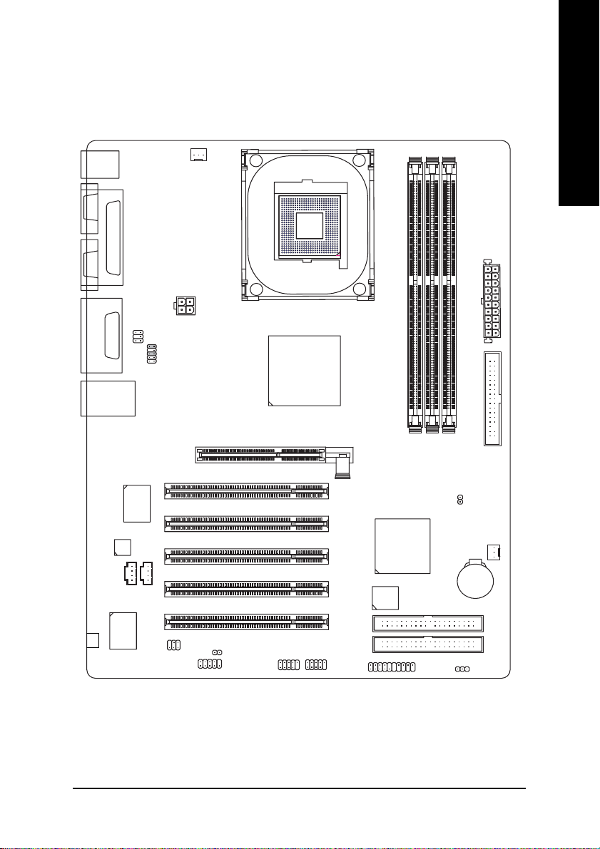
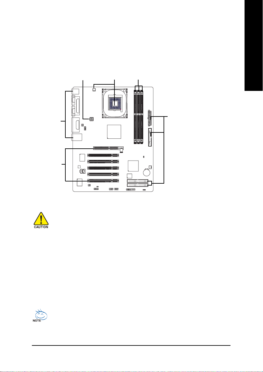
8I845GE-RZ Series Motherboard Layout
English
KB_MS
COMA
VGA
LINE_OUT
LINE_IN
MIC_IN
USB
#
-C
LPT
Game
LAN*
CODEC
CD_IN
SUR_CEN
F_AUDIO
RTL8100C*
IT8712
CPU_FAN
ATX_12V
AUX_IN
SPDIF_IO
ATX
Socket 478
8I845GE-RZ
Intel 845GE
AGP
DDR1
DDR2
DDR3
FDD
CLR_CMOS
PCI1
PCI2
PCI3
PCI4
CI
COMB
F_USB1
PCI5
F_USB2
Intel ICH4
BIOS
F_PANEL
SYS _FAN
BAT
IDE2
IDE1
PWR_LED
"*" For 8I845GE-RZ only.
"#" For 8I845GE-RZ-C only.
Introduction- 7 -
Page 8
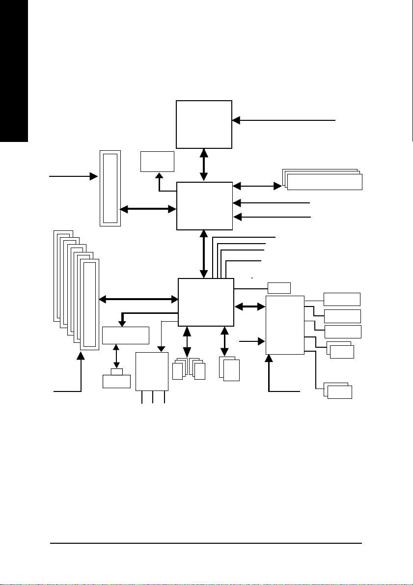
Block Diagram
English
AGPCLK
(66MHz)
5 PCI
PCICLK
(33MHz)
AGP 4X
RTL8100C*
RJ45*
VGA Port
AC97 Link
AC97
CODEC
MIC
LINE-IN
Socket 478
Processor
Intel 82845GE
Intel ICH4
6 USB
Ports
LINE-OUT
Host
Interface
LPC BUS
24 MHz
ATA33/66/100
IDE Channels
CPUCLK+/- (100/133MHz)
266/333MHz
DDR RAM
GMCHCLK(66MHz)
HCLK+/- (100/133MHz)
66 MHz
33 MHz
14.318 MHz
48 MHz
BIOS
IT8712
33 MHz
Game Port
Floppy
LPT Port
COM
Ports
PS/2
KB/Mouse
"*" For 8I845GE-RZ only.
8I845GE-RZ Series Motherboard
- 8 -
Page 9
Hardware Installation Process
To set up your computer, you must complete the following steps:
Step 1- Install the Central Processing Unit (CPU)
Step 2- Install memory modules
Step 3- Install expansion cards
Step 4- Install I/O Peripherals cables
Step 1
Step 2Step 4
English
Step 4
Step 4
Step 3
Step 1: Install the Central Processing Unit (CPU)
Before installing the CPU, please comply with the following conditions:
1. Please make sure that the motherboard supports the CPU.
2. Please take note of the one indented corner of the CPU. If you install the CPU
in the wrong direction, the CPU will not insert properly. If this occurs, please change
the insert direction of the CPU.
3. Please add an even layer of heat sink paste between the CPU and heatsink.
4. Please make sure the heatsink is installed on the CPU prior to system use, otherwise
overheating and permanent damage of the CPU may occur.
5. Please set the CPU host frequency in accordance with the processor specifications. It
is not recommended that the system bus frequency be set beyond hardware specifica
tions since it does not meet the required standards for the peripherals. If you wish to set
the frequency beyond the proper specifications, please do so according to your hard
ware specifications including the CPU, graphics card, memory, hard drive, etc.
HT functionality requirement content :
Enabling the functionality of Hyper-Threading Technology for your computer system requires all of the following platform components:
- CPU: An Intel® Pentium 4 Processor with HT Technology
- Chipset: An Intel® Chipset that supports HT Technology
- BIOS: A BIOS that supports HT Technology and has it enabled
- OS: An operation system that has optimizations for HT Technology
- 9 - Hardware Installation Process
Page 10
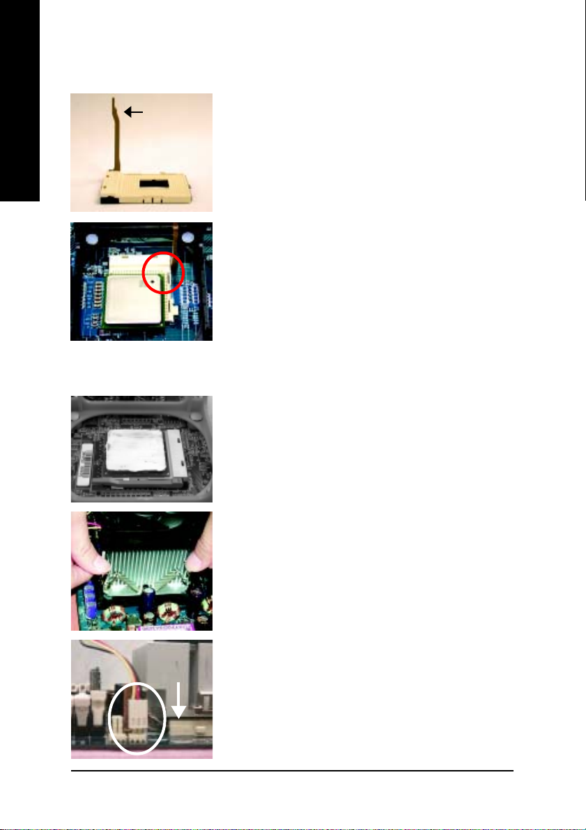
Step 1-1: CPU Installation
English
Step 1-2: CPU Cooling Fan Installation
Socket
Actuation
Lever
Figure 1.
Pull the rod to the 90-degree directly.
Figure 2.
Locate Pin 1 in the socket and look for a (golden) cut edge on the
CPU upper corner. Insert the CPU into the socket. (Do not force the
CPU into the socket.) Then move the socket lever to the locked
position while holding pressure on the center of the CPU.
Figure 1.
Apply the thermal tape(or grease) to provide better heat conduction
between your CPU and cooling fan.
8I845GE-RZ Series Motherboard
Figure 2.
Fasten the cooling fan supporting-base onto the CPU socket on the
motherboard.
Figure 3.
Make sure the CPU fan is plugged to the CPU fan connector, and
then the installation is completed.
- 10 -
Page 11
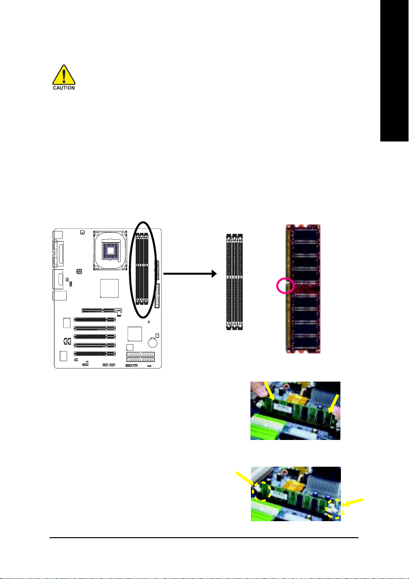
Step 2: Install Memory Modules
Before installing the memory modules, please comply with the following conditions:
1. Please make sure that the memory used is supported by the motherboard. It is recommended that memory of similar capacity, specifications and brand be used.
2. Before installing or removing memory modules, please make sure that the computer
power is switched off to prevent hardware damage.
3. Memory modules have a foolproof insertion design. A memory module can be
installed in only one direction. If you are unable to insert the module, please switch the
direction.
4. Because of chipset (Intel 845PE/GE) limitations, DDR333 memory modules are supported
only when you install a Pentium 4 processor with 533MHz FSB. A Pentium 4 processor with
400MHz FSB will support DDR266 memory modules.
The motherboard has 3 dual inline memory module (DIMM) sockets. The BIOS will automatically
detects memory type and size. To install the memory module, just push it vertically into the DIMM
socket. The DIMM module can only fit in one direction due to the notch. Memory size can vary between
sockets.
notch
English
Fig.1
The DIMM socket has a notch, so the DIMM memory module
can only fit in one direction. Insert the DIMM memory module
vertically into the DIMM socket. Then push it down.
Fig.2
Close the plastic clip at both edges of the DIMM sockets to lock
the DIMM module.
Reverse the installation steps when you wish to remove the
DIMM module.
- 11 - Hardware Installation Process
DDR memory module
Fig. 1
Fig. 2
Page 12
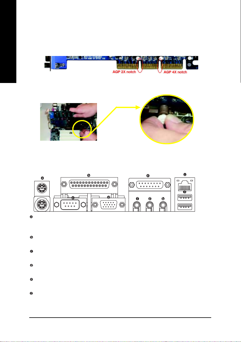
Step 3: Install AGP Card
1. Read the related expansion card's instruction document before installing the expansion card into
English
2. Please make sure your AGP card is AGP 4X (1.5V).
3. Please carefully pull out the small white- drawable bar at the end of the AGP slot when you try to
Step 4: Install I/O Peripherals Cables
Step 4-1: I/O Back Panel Introduction
the computer.
install/ Uninstall the AGP card. Please align the AGP card to the onboard AGP slot and press firmly
down on the slot .Make sure your AGP card is locked by the small white- drawable bar.
AGP Card
*
PS/2 Keyboard and PS/2 Mouse Connector
To install a PS/2 port keyboard and mouse, plug the mouse to the upper port (green) and the keyboard
to the lower port (purple).
Parallel Port
The parallel port allows connection of a printer, scanner and other peripheral devices.
Serial Port
Devices like mouses, modems, and etc. can be connected to Serial port.
VGA Port
Monitor can be connected to VGA port.
Game/MIDI port
This connector supports joystick, MIDI keyboard and other related audio devices.
Line Out (Front Speaker Out)
Connect the stereo speakers, earphone or front surround channels to this connector.
"*" For 8I845GE-RZ only.
8I845GE-RZ Series Motherboard
- 12 -
Page 13

Line In
Devices like CD-ROM, walkman etc. can be connected to Line In jack.
MIC In
Microphone can be connected to MIC In jack.
LAN Port *
The LAN port provides Internet connection.
USB port
Before you connect your device(s) into USB connector(s), please make sure your device(s) such
as USB keyboard, mouse, scanner, zip, speaker...etc. have a standard USB interface. Also make
sure your OS supports USB controller. If your OS does not support USB controller, please contact OS vendor for possible patch or driver upgrade. For more information please contact your
OS or device(s) vendors.
Step 4-2: Connectors Introduction
1
32
13
10
5
17
7
11
4
9
6
English
1) A TX_12V
2) ATX
3) CPU_FAN
4) SYS_FAN
5) FDD
6) IDE1 / IDE2
7) AUX_IN
8) F_PANEL
9) BAT
"*" For 8I845GE-RZ only.
81612
14
1815
10) F_AUDIO
11) CD_IN
12) SPDIF_IO
13) SUR_CEN
14) F_USB1 / F_USB2
15) CI
16) COMB
17) CLR_CMOS
18) PWR_LED
- 13 - Hardware Installation Process
Page 14

1/2) ATX_12V/ATX (Power Connector)
English
With the use of the power connector, the power supply can supply enough stable power to all
the components on the motherboard. Before connecting the power connector, please make sure
that all components and devices are properly installed. Align the power connector with its
proper location on the motherboard and connect tightly.
The ATX_12V power connector mainly supplies power to the CPU. If the ATX_12V power
connector is not connected, the system will not start.
Caution!
Please use a power supply that is able to handle the system voltage requirements. It is
recommended that a power supply that can withstand high power consumption be used (300W
or greater). If a power supply is used that does not provide the required power, the result can
lead to an unstable system or a system that is unable to start.
4
3
11
20
2
1
Pin No. Definition
1
1 3.3V
2 3.3V
3 GND
4 VCC
5 GND
6 VCC
7 GND
8 Power Good
10
9 5V SB (stand by +5V)
10 +12V
Pin No. Definition
1 GND
2 GND
3 +12V
4 +12V
Pin No. Definition
11 3.3V
12 -12V
13 GND
14 PS_ON(soft on/off)
15 GND
16 GND
17 GND
18 -5V
19 VCC
20 VCC
3) CPU_FAN (CPU FAN Connector)
Please note, a proper installation of the CPU cooler is essential to prevent the CPU from running
under abnormal condition or damaged by overheating.The CPU fan connector supports Max.
current up to 600 mA.
1
Pin No. Definition
1 GND
2 +12V
3 Sense
8I845GE-RZ Series Motherboard
- 14 -
Page 15

4) SYS_FAN (System FAN Connector)
This connector allows you to link with the cooling fan on the system case to lower the system
temperature.
Pin No. Definition
1
1 GND
2 +12V
3 Sense
5) FDD (Floppy Connector)
Please connect the floppy drive ribbon cables to FDD. It supports 360K,720K,1.2M,1.44M and
2.88Mbytes floppy disk types.
The red stripe of the ribbon cable must be the same side with the Pin1.
33
34
English
2
6) IDE1/ IDE2 (IDE1/IDE2 Connector)
Please connect first harddisk to IDE1 and connect CDROM to IDE2.
The red stripe of the ribbon cable must be the same side with the Pin1.
39
40
- 15 - Hardware Installation Process
1
1
IDE2
IDE1
2
Page 16

7) AUX_IN (AUX In Connector)
English
8) F_PANEL (2x10 pins connector)
Connect other device (such as PCI TV Tunner audio out) to the connector.
1
Pin No. Definition
1 AUX-L
2 GND
3 GND
4 AUX-R
Please connect the power LED, PC peaker, reset switch and power switch etc. of your chassis front
panel to the F_PANEL connector according to the pin assignment above.
HD (IDE Hard Disk Active LED) Pin 1: LED anode(+)
SPK (Speaker Connector) Pin 1: VCC(+)
RST (Reset Switch) Open: Normal Operation
PW (Soft Power Connector) Open: Normal Operation
MSG (Message LED/Power/ Pin 1: LED anode(+)
Sleep LED) Pin 2: LED cathode(-)
NC NC
8I845GE-RZ Series Motherboard
Soft Power
MSGMSG+
HD+
HD-
Connector
2
1
Reset Switch
PW+
RST-
Message LED/Power/
Sleep LED
IDE Hard Disk
Active LED
Pin 2: LED cathode(-)
Pin 2- Pin 3: NC
Pin 4: Data(-)
Close: Reset Hardware System
Close: Power On/Off
- 16 -
RST+
PW-
Speaker
Connector
SPK-
SPK+
20
19
NC
Page 17

9) BAT (Battery)
+
CAUTION
Danger of explosion if battery is incorrectly
replaced.
Replace only with the same or equivalent type
recommended by the manufacturer.
Dispose of used batteries according to the
manufacturer's instructions.
If you want to erase CMOS...
1. Turn OFF the computer and unplug the power cord.
2. Remove the battery, wait for 30 second.
3. Re-install the battery.
4. Plug the power cord and turn ON the computer.
10) F_AUDIO (Front Audio Panel Connector)
If you want to use Front Audio connector, you must remove jumpers on pins 5-6, 9-10. In order to
utilize the front audio header, your chassis must have front audio connector. Also please make sure
the pin assigments on the cable are the same as the pin assigments on the MB header. To find out if
the chassis you are buying support front audio connector, please contact your dealer. Please note,
you can have the alternative of using front audio connector or of using rear audio connector to play
sound.
English
10 9
2
1
Pin No. Definition
1 MIC
2 GND
3 REF
4 POWER
5 FrontAudio(R)
6 RearAudio(R)
7 Reserved
8 No Pin
9 FrontAudio (L)
10 RearAudio(L)
- 17 - Hardware Installation Process
Page 18

11) CD_IN (CD In Connector)
English
12) SPDIF_IO (SPDIF In/Out Connector)
Connect CD-ROM or DVD-ROM audio out to the connector.
1
Pin No. Definition
1 CD-L
2 GND
3 GND
4 CD-R
The SPDIF output is capable of providing digital audio to external speakers or compressed AC3
data to an external Dolby Digital Decoder. Use this feature only when your stereo system has
digital input function. Use SPDIF IN feature only when your device has digital output function.Be
careful with the polarity of the SPDIF_IO connector. Check the pin assignment carefully while
you connect the SPDIF_IO cable, incorrect connection between the cable and connector will
make the device unable to work or even damage it. For optional SPDIF_IO cable, please contact
your local dealer.
Pin No. Definition
6
2
1
5
1 VCC
2 No Pin
3 SPDIF
4 SPDIFI
5 GND
6 GND
13)SUR_CEN (Surround Center Connector)
Please contact your nearest dealer for optional SUR_CEN cable.
65
1
2
8I845GE-RZ Series Motherboard
- 18 -
Pin No. Definition
1 SUR OUTL
2 SUR OUTR
3 GND
4 No Pin
5 CENTER_OUT
6 BASS_OUT
Page 19

14)F_ USB1 / F_USB2 (Front USB Connector)
Be careful with the polarity of the F_USB connector. Check the pin assignment carefully while
you connect the F_USB cable, incorrect connection between the cable and connector will make
the device unable to work or even damage it. For optional F_USB cable, please contact your local
dealer.
Pin No. Definition
1 Power
2
1
10
9
2 Power
3 USB DX4 USB Dy5 USB DX+
6 USB Dy+
7 GND
8 GND
9 No Pin
10 NC
15) CI (Chassis Intrusion, Case Open)
This 2-pin connector allows your system to detect if the chassis cover is removed. You can
check the "Case Open" status in BIOS.
Pin No. Definition
1
1 Signal
2 GND
English
16) COMB (COMB Connector)
Be careful with the polarity of the COMB connector. Check the pin assignment carefully while you
connect the COMB cable because incorrect connection between the cable and connector will
make the device unable to work or even damage it. For optional COMB cable, please contact your
local dealer.
10
2
19
- 19 - Hardware Installation Process
Pin No. Definition
1 NDCDB2 NSINB
3 NSOUTB
4 NDTRB5 GND
6 NDSRB7 NRTSB8 NCTSB9 NRIB10 No Pin
Page 20

17) CLR_CMOS (Clear CMOS)
You may clear the CMOS data to its default values by this jumper. To clear CMOS, temporarily short
pins 1-2. Default doesn't include a jumper on pins 1-2 to prevent improper use of this header.
English
18) PWR_LED
1
Open: Normal
1
Short: Clear CMOS
PWR_LED is connected with the system power indicator to indicate whether the system is on/off. It
will blink when the system enters suspend mode. If you use dual color LED, power LED will turn to
another color.
Pin No. Definition
1 MPD+
2 MPD-
1
3 MPD-
8I845GE-RZ Series Motherboard
- 20 -
Page 21

Chapter 2 BIOS Setup
Chapter 2 pr ovides an overview of the BIOS Setup Progr am, which allows users to m odify the basic
system configurations. Th is type of information is stored in battery-backed CMOS RAM so that it retains
the Setup inform ation when the power is turned off.
ENTERING BIOS Setup
Turning o n the computer and pressing <Del> imm ediately allow you to enter BIOS Setup. If you need
more ad vanced BIOS settings, please press Ctrl and F1 keys on the BIOS main screen to acce ss the
the advan ced BIOS settings.
CONTROL KEYS
< >< >< >< > Move to select item
<Enter> Select Item
<Esc> Main Menu - Q uit and not save changes into CM OS Status Page Setup M enu
and Option Page Setup Menu - Exit current page and return to Main Menu
<+/PgUp> Increase the nu mer ic value or make changes
<-/PgDn> Decrease the numeric va lue or make changes
<F1> General help, only for Status Page Setup Menu and Option Page Setup Menu
<F2> Item Help
<F5> Restore the previous CMOS value from CMOS, only for Option Page Setup Menu
<F6> Load the file-safe default CMOS value from BIOS default table
<F7> Load the Optimized Defaults
<F8> Q-Flash utility
<F9> System Information
<F10> Save all the CMOS ch anges, only for Main M enu
Main Menu
The on-line description of the highlighted setup function is disp layed at th e bottom of the screen.
Status Page Setup Menu / Option Page Setup Menu
Press F1 to pop up a sm all help window that describes the appr opriate keys to use and the possible
selections for the highlighted item. To exit the Help Window, press <Esc>.
English
The Main Menu (For example: BI OS Ver. : F1)
Once you enter Award BIOS CM OS Setup Utility, the Main Menu (as figure below) will appear on the
scree n. The Main Me nu allows you to select from eight setup functions and two exit choices. Use
arrow keys to select among the items and press <Enter> to accept or enter the sub-menu.
CMOS Setup Utility-Copyright (C) 1984-2004 Awa rd Soft ware
} St andard CMOS Featur es
} Ad vanced BIOS Featur es
} In tegrat ed Per iphera ls
} Po wer Man agement Set up
} Pn P/PCI Config uratio ns
} PC Health Stat us
} Fr equency /Voltag e Con trol
Ese: Quit higf: Select Item
F8: Q-Flash F10: Save & Exit Setup
Time, Date, Hard Disk Type...
Top Performance
Load Fail-Safe Defaults
Load Optimized Defaults
Set Supervisor Password
Set User Password
Save & Exit Setup
Exit Without Saving
- 21 - BIOS Setup
Page 22

If you can't find the settings you want, press Ctrl and F1 in BIOS main menu to
access the hidden advanced options.
English
• Standard CMOS Features
• Advanced BIOS Features
• Integrated Peripherals
• Power Management Setup
• PnP/PCI Configurations
• PC Health Status
• Frequency/Voltage Control
• Top Performance
• Load Fail-Safe Defaults
• Load Optimized Defaults
• Set Supervisor Password
• Set User Password
• Save & Exit Setup
• Exit Without Saving
This setup pa ge includes all the item s in standard compatible BIOS.
This setup page includes a ll the items of Award special enhance d features.
This setup pag e includes all onboard per ipherals settings.
This setup pa ge includes all the items of Green function features.
This setup page includes all the configurations of PCI & PnP ISA resources.
This setup pa ge includes the information of the system auto-detected temperature, voltage, and
fan speed.
This se tup page allows to control CPU clock a nd frequency ratio.
If you wish to maxim ize the perform ance of your system , try to enable To p Performance.
Fail-Sa fe Defaults indicates the value of the system pa rameters with which the system would be
in safe configuration.
Optimized Defaults indicates the value of the system param eters which the system would be in
best performance configuration.
Change, set, or disable password. It allows you to limit access to the system and BIOS Setup, or
just to BIOS Setup.
Change , set, or disable password. It allows you to limit access to the system.
Save CMOS value settings to CMOS and exit BIOS Setup.
Abandon all CMOS value changes and exit BIOS Setup.
- 22 -8I845GE-RZ Series Motherboard
Page 23

Standard CMOS Features
CMOS Setup Utility-Copyright (C) 1984-2004 Awa rd Soft ware
Date (mm:dd:yy) Fri, Jan 9 2004
Time (hh:mm:ss) 22:31:24
} IDE Pri mary Master [None]
} IDE Pri mary S lave [None]
} IDE Sec ondary Master [None]
} IDE Sec ondary Slave [None]
Drive A [1.44M, 3.5"]
Drive B [None]
Floppy 3 Mode Support [Disabled]
Halt On [All, But Keyboard]
Base Memory 640K
Extended Memory 127M
Total Memory 128M
higf: Move Enter: Select +/-/PU/PD: Value F10: Save ESC: Exit F1: General Help
F5: Previous Values F6: Fail-Safe Defa ults F7: Optimized Defaults
Date
The date format is <week>, <month>, <day>, <year>.
Week From Sun. to Sat., determined by the BIOS and for displa y only.
Month From Jan. to Dec.
Day From 1st to 31st (or the maximum allowed in the month).
Year From Year 1999 to 2098.
Time
The format used to express time is hours:minutes:seconds. The time is calculated based on the
24-hour military-time clock. For example, 1 p.m. is 13:00:00.
IDE Primary Master, Slave / IDE Secondary Master, Slave
IDE HDD Auto-Detection Press "Enter" to select this option for autom atic device detection.
IDE Primary/Se condary M aster(Slave) setup You can use one of the three m ethods below:
Auto Allows BIOS to autom atically detect IDE d evices dur ing POST. (Default value)
None Select this if no IDE devic es are used and the system will skip the automatic
detection step and a llow for faster system start up.
Manual User can manually input the cor rect settings
Access Mode Use this to set the access mode for the hard drive. T he four options are:
Hard drive information should be labeled on the outside drive casing.
Enter the appropriate option based on this information.
Capa city Capacity of currently installed hard disk.
Cylind er Number o f cylinders
Head Number of heads
Precomp Write precomp
Landing Zone Landing z one
Sector Number of sectors
CHS/LBA/L arge/Auto ( Default:Auto)
Standard CMOS Features
Item Help
Menu Level }
Change the day, month,
year
<Week>
Sun. to Sat.
<Month>
Jan. to Dec.
<Day>
1 to 31 (or maximum
allowed in the month)
<Year>
1999 to 2098
English
- 23 - BIOS Setup
Page 24

English
Base Memory
Extended Memory
Drive A / Drive B
The catego ry identifies the types of floppy disk (drive A a nd drive B) installed in the computer.
None No floppy disk is installed
360K, 5.25" 5.25 inch PC-type standard drive; 360K byte cap acity.
1.2M, 5. 25" 5.25 inch AT-type high-density drive; 1.2M byte capacity
(3.5 in ch when 3 Mode is Enabled).
720K, 3.5" 3.5 inch double -sided drive; 720K byte capacity
1.44M, 3 .5" 3.5 inch double-sided drive; 1 .44M byte capacity.
2.88M, 3 .5" 3.5 inch double-sided drive; 2 .88M byte capacity.
Floppy 3 Mode Support (for Japan Area)
Disabled Normal Floppy Drive. (Default value)
Drive A Enable Drive A 3 M ode support.
Drive B Enable Drive B 3 M ode support.
Both Enable both Drive A and B 3 Mode support.
Halt on
The categor y d etermines whether the computer will stop if an error is detected during power up.
All Errors Whenever the BIOS detects a non-fatal error the system will stop.
No Errors The system boot will not stop for any error that may be detected and you
will be prompted.
All, Bu t Keyboard The system boot will not stop for a keyboard error ; it will stop for all other
errors. (Default value)
All, But Diskette The system boot will not stop for a disk error; it will stop for all other errors.
All, But Disk/Key The system boot will not stop for a keyboard or disk error; it will stop for all
other errors.
Memory
The ca tegory is display-only which is d etermined by POST (Power On Self Test) of the BIOS.
The POST of the BIOS will determine the am ount of base (or conventional) memory installed
in the system.
The va lue of the base mem ory is typically 512K for systems with 512K memory installe d on
the motherboar d, or 640K for systems with 640K or m ore m emory installed on the motherboard.
The BIOS determines how much extended m emory is present during the POST.
This is the amount of m emory located abo ve 1 MB in the CPU's mem ory address map.
Total Memory
This item displays the me mory size that used.
- 24 -8I845GE-RZ Series Motherboard
Page 25

Advanced BIOS Features
CMOS Setup Utility-Copyright (C) 1984-2004 Awa rd Soft ware
First Boot Device [Floppy]
Second Boot Device [HDD-0]
Third Boot Device [CDROM]
Boot Up Floppy Seek [Disabled]
Password Check [Setup]
CPU Hyper-Threading
Limit CPUID Max. to 3
Init Display First [Onboard/AGP]
Graphics Aperture Size
Graphics Share Memory
higf: Move Enter: Select +/-/PU/PD: Value F10: Save ESC: Exit F1: General Help
F5: Previous Values F6: Fail-Safe Defa ults F7 : Optim ized Defaul ts
note 1
note 2
note 3
note 4
[Enabled]
[Enabled]
[128MB]
[8M]
Note 1: This option appears only when the Intel Pentium® 4 processor you install on the system supports
the Hyper-Threading Technology.
Note 2: This option is available only when you install an Intel® Prescott processor
Note 3/4: Th is option is available only when you use the onboa rd VGA function.
First / Second / Third Boot Device
Floppy Se lect your boot device priority by Floppy.
LS120 Select your boo t device priority by LS120.
HDD-0~3 Select your boot device priority by HDD-0~3.
SCSI Select your boot device priority by SCSI.
CDROM Select your boot device priority by CDROM.
ZIP Select your boot device priority by ZIP.
USB-FDD Se lect your boot device priority by USB-FDD.
USB-ZIP Select your boo t device priority by USB-ZIP.
USB-CDROM Select your boot device pr iority by USB-CDROM.
USB-HDD Select your boot device prio rity by USB-HDD.
LAN Select your boot device prio rity by LAN.
Disabled Select your boot device priority by Disabled.
Advanced BIOS Features
Item Help
Menu Level }
Select Boot Device
Priority
[Floppy]
Boot from floppy
[LS120]
Boot from LS120
[HDD-0]
Boot from First HDD
[HDD-1]
Boot from second HDD
English
Boot Up Floppy Seek
During POST, BIOS will determine the floppy disk drive installed is 40 or 80 tracks. 360K type is
40 tracks 720K, 1. 2M and 1.44M are all 80 tracks.
Disabled BIOS will not search for the type of floppy disk drive by track number. Note
that there will n ot be any warning message if the drive installed is 360K.
Enabled BIOS searches for floppy disk drive to determine if it is 40 or 80 tracks. Note
(Default value)
that BIOS can not tell from 720K, 1.2M or 1.44M drive type as they are all 80
tracks.
- 25 - BIOS Setup
Page 26

English
Password Check
Setup The system will b oot but will not access to Setup page if the correct password
is not entered at the prompt. (Default value)
System The system will not boot and will not access to Setup page if the correct
password is not entered at the prom pt.
CPU Hyper-Threading
This option is available only when you install an Intel® Hyper-Thre ading processor.
Disabled Disab le CPU Hyper Threading.
Enabled Enable CPU Hyper T hreading Feature. Please note that this feature is only
working for operating system with multi processors m ode supported.
(Default value)
Limit CPUID Max. to 3
This op tion is available only when you install an Intel® Prescott processor.
Enabled Limit CPUID Maximum value to 3 when using older OS like NT 4. (Defaults
value )
Disabled Disa ble CPUID Lim it for Windows XP.
Init Display First
Select the first initation of the monitor display from onboard/AGP or PCI VGA card.
PCI Set Init Display First to PCI.
Onboard/AGP Set Init Displa y First to onboard/AGP. (Default value)
Graphics Aperture Size
This op tion is available only when you use the onboar d VGA function.
128MB Set Graphics Aperture Size to 128MB. (Default value)
Disabled Disable this function.
Graphics Share Memory
This op tion is available only when you use the onboar d VGA function.
8MB Set Graph ics Share Mem ory to 8MB. (Default value)
1MB Set Graph ics Share M emory to 1MB.
- 26 -8I845GE-RZ Series Motherboard
Page 27

Integrated P eripherals
CMOS Setup Utility-Copyright (C) 1984-2004 Awa rd Soft ware
On-Chip Primary PCI IDE [Enabled]
On-Chip Secondary PCI IDE [Enabled]
IDE1 Conductor Cable [Auto]
IDE2 Conductor Cable [Auto]
USB Controller [Enabled]
USB Keyboard Support [Disabled]
USB Mouse Support [Disabled]
AC97 Audio [Auto]
Onboard H/W LAN
Onboard LAN Boot ROM
Onboard Serial Port 1 [3F8/IRQ4]
Onboard Serial Port 2 [2F8/IRQ3]
Onboard Parallel Port [378/IRQ7]
Parallel Port Mode [SPP]
x ECP Mode Use DMA 3
Game Port Address [201]
Midi Port Address [Disabled]
x Midi Port IRQ 10
higf: Move Enter: Select +/-/PU/PD: Value F10: Save ESC: Exit F1: General Help
F5: Previous Values F6: Fail-Safe Defa ults F7 : Optim ized Defaul ts
*
*
On-Chip Prim ary PCI IDE
Enabled Enable onboard 1st channel IDE port. (Defau lt value)
Disabled Disable onboard 1st channel IDE port.
On-Chip Secondary PCI IDE
Enabled Enable onboard 2nd channel IDE port. (Default value)
Disabled Disable onboard 2nd channel IDE port.
IDE1 Conductor Cable
Auto BIOS auto detects IDE1 condu ctor cable. (Default Value)
ATA66/100 Set IDE1 Conductor Cable to ATA66/100 (80-pin). Please m ake sure your IDE
device and cable is compatible with ATA66/100.
ATA33 Set IDE1 Conductor Cable to ATA33 (40-pin). Please make sure yo ur IDE
device and cable is compatible with ATA33.
IDE2 Conductor Cable
Auto BIOS auto detects IDE2 condu ctor cable. (Default Value)
ATA66/100 Set IDE2 Conductor Cable to ATA66/100 (80-pin). Please m ake sure your IDE
device and cable is compatible with ATA66/100.
ATA33 Set IDE2 Conductor Cable to ATA33 (40-pin). Please make sure yo ur IDE
device and cable is compatible with ATA33.
Integrated Peripherals
[Enabled]
[Disabled]
Item Help
Menu Level u
If a hard disk
controller card is
used, set at Disabled
[Enabled]
Enable onboard IDE
PORT
[Disabled]
Disable onboard IDE
PORT
English
USB Controller
Enabled Enable USB Controller. (Default value)
Disabled Disable USB Controller.
"*" Fo r 8I845GE-RZ only.
- 27 - BIOS Setup
Page 28

USB Keyboard Support
Enabled Enable USB Keyboard Support.
Disabled Disable USB Keyboard Suppo rt. (Default value)
English
"*" Fo r 8I845GE-RZ only.
USB Mouse Support
Enabled Enable USB Mouse Support.
Disabled Disable USB M ouse Support. (Default value)
AC97 Audio
Auto Autodetect onboard AC'97 audio function. (Default value)
Disabled Disable this function.
Onboard H/W LAN *
Enabled Enabled onboard LAN function. (Default value)
Disabled Disable this function.
Onboard LAN Boot ROM *
Enabled Enable to invoke the boot ROM of the onboard LAN chip.
Disabled Disable this function. (Default value)
Onboard Serial Port 1
Disabled Disable onboard Serial port 1.
3F8/IRQ4 Enable onboard Serial port 1 and address is 3F8/IRQ4. (Default value)
2F8/IRQ3 Enable onboard Serial port 1 and address is 2F8/IRQ3.
3E8/IRQ4 Enable onboard Serial port 1 and address is 3E8/IRQ4.
2E8/IRQ3 Enable onboard Serial port 1 and address is 2E8/IRQ3.
Auto BIOS will automatically setup the Port 1 address.
Onboard Serial Port 2
Disabled Disable onboard Serial port 2
3F8/IRQ4 Enable onboard Serial port 2 and address is 3F8/IRQ4.
2F8/IRQ3 Enable onboard Serial port 2 and address is 2F8/IRQ3. (Default value)
3E8/IRQ4 Enable onboard Serial port 2 and address is 3E8/IRQ4.
2E8/IRQ3 Enable onboard Serial port 2 and address is 2E8/IRQ3.
Auto BIOS will automatically setup the Port 2 address. .
Onboard Parallel Port
Disabled Disable onboard LPT port.
378/IRQ7 Enable onboard LPT port and address is 378/IRQ7. (Default Value)
278/IRQ5 Enable onboard LPT port and address is 278/IRQ5.
3BC/IRQ7 Enable onboard LPT p ort and address is 3BC/IRQ7.
Parallel Port Mode
SPP Use Parallel port as Standard Parallel Port. (Default Value)
EPP Use Parallel port as Enhanced Parallel Port.
ECP Use Parallel po rt as Extended Capabilities Port.
ECP+EPP Use Parallel port as ECP & EPP m ode.
- 28 -8I845GE-RZ Series Motherboard
Page 29

ECP Mode Use DMA
This feature allows you to select Direct Mem ory Access(DMA) channel if the ECP mode selected.
This o ption is available only when Pa rallel Po rt Mode is set to ECP or ECP+EPP.
1 Set ECP Mode Use DMA to 1.
3 Set ECP M ode Use DM A to 3. (Default value)
Game Port Address
Disabled Disable this function
201 Enable this function and set gam eport address to 201. (Default value)
209 Enable this function and set gameport address to 209.
Midi Port Address
Disabled Disable this function. (Default value)
330 Enable this function and set midiport address to 330.
300 Enable this function and set midiport address to 300.
Midi Port IRQ
This option is available when the Midi Por t Address is not set to "Disabled."
5 Set midip ort IRQ to 5.
10 Set midipo rt IRQ to 10. ( Default value)
Power M anagement Setup
CMOS Setup Utility-Copyright (C) 1984-2004 Awa rd Soft ware
ACPI Suspend Type [S1(POS)]
Power LED in S1 state [Blinking]
Soft-Off by PWR-BTTN [Instant-Off]
PME Event Wake Up [Enabled]
ModemRingOn [Enabled]
Resume by Alarm [Disabled]
x Date (of Month) Alarm Everyday
x Time (hh:mm:ss) Alarm 0 : 0 : 0
Power On by Mouse [Disabled]
Power On by Keyboard [Disabled]
x KB Power ON Password Enter
AC BACK Function [Soft-Off]
Power Management Setup
Item Help
Menu Level u
[S1]
Set suspend type to
Power On Suspend under
ACPI OS
[S3]
Set suspend type to
Suspend to RAM under
ACPI OS
English
higf: Move Enter: Select +/-/PU/PD: Value F10: Save ESC: Exit F1: General Help
F5: Previous Values F6: Fail-Safe Defa ults F7 : Optim ized Defaul ts
ACPI Suspend Type
S1(POS) Set ACPI suspend type to S1. (Default Value)
S3(STR) Set ACPI suspend type to S3.
Power LED in S1 state
Blinking The Power LED will be b linking during S1 state. (Default value)
Dual/OFF Th e Power LED will be turne d off or change color.
- 29 - BIOS Setup
Page 30

English
Soft-off by PWR-BTTN
Instant -Off Once a user presses the power button, the system will be turned off instantly.
(Default Value)
Delay 4 sec. Press power button for 4 seconds to turn off the system. System enters suspend
mode if the power button is pressed for less than 4 seconds.
PME Event Wake Up
Disabled Disable this function.
Enabled Enable PME Event Wake up. (Default Value)
ModemRingOn
Disabled Disable M odem Ring on function.
Enabled Enable Modem Ring on function. (Default Value)
Resume by Alarm
You can enable Resume by Alarm and ke y in month/date/tim e to turn on system.
Disabled Disable this function. (Default Value)
Enabled Enable alarm function to POWER ON system.
If Resume by Alarm is Enabled.
Date (of Month) Alarm: Everyday, 0~31
Time ( hh: mm: ss) Alarm: (0~23) : (0~59) : (0~59)
Power On by Mouse
Double Click Double-click the mouse to turn on the system.
Disabled Disable this function. (Default Value)
Power On by Keyboard
Keyboard 98 If your keyboard has a “Power” button, enable this function to press the button to
turn off the system.
Passwor d Input password (from 1 to 5 characters) and press Enter to set the Keyboard
Power On Passwor d.
Disabled Disable this function. (Default Value)
KB Power On Password
When "Power On by Keyboard" is set at Password, you can set the password here.
Enter Input password (from 1 to 5 ch aracters) and press Enter to set the Keyboard
Power On password.
AC BACK Function
Soft-Off When AC-power back to the system, the system will be in "Off" state.
(Default value)
Full-On When AC-power back to the system, the system always in "On" state.
Memory When AC-power back to the system, the system will return to the L ast state
before AC- power off.
- 30 -8I845GE-RZ Series Motherboard
Page 31

PnP/PCI Configurations
CMOS Setup Utility-Copyright (C) 1984-2004 Awa rd Soft ware
PCI1/5 IRQ Assignment [Auto]
PCI2 IRQ Assignment [ Auto]
PCI3 IRQ Assignment [ Auto]
PCI4 IRQ Assignment [ Auto]
higf: Move Enter: Select +/-/PU/PD: Value F10: Save ESC: Exit F1: General Help
F5: Previous Values F6: Fail-Safe Defa ults F7: Optimized Defaults
PCI1/5 IRQ Assignment
Auto Auto assign IRQ to PCI 1/5. (Default value)
3,4,5,7,9,10,11,12,1 4,15 Set IRQ 3,4,5,7,9,10,1 1,12,14,15 to PCI 1/5.
PCI2 IRQ Assignment
Auto Auto assign IRQ to PCI 2. (Default value)
3,4,5,7,9,10,11,12,14,15 Set IRQ 3,4,5,7 ,9,10,11,12,14,15 to PCI 2.
PCI3 IRQ Assignment
Auto Auto assign IRQ to PCI 3. (Default value)
3,4,5,7,9,10,11,12,14,15 Set IRQ 3,4,5,7 ,9,10,11,12,14,15 to PCI 3.
PnP/PCI Configurations
Item Help
Menu Level }
Device(s) using this
INT:
USB 1.1 Host Cntrlr
-Bus 0 Dev29 Func 2
English
PCI4 IRQ Assignment
Auto Auto assign IRQ to PCI 4. (Default value)
3,4,5,7,9,10,11,12,14,15 Set IRQ 3,4,5,7 ,9,10,11,12,14,15 to PCI 3.
- 31 - BIOS Setup
Page 32

PC Health Status
English
higf: Move Enter: Select +/-/PU/PD: Value F10: Save ESC: Exit F1: General Help
CMOS Setup Utility-Copyright (C) 1984-2004 Awa rd Soft ware
Reset Case Open Status [Disabled]
Case Opened No
Vcore 1.348V
DDR25V 2.544V
+3.3V 3.360V
+12V 11.858V
Current CPU Temperature 27° C
Current CPU FAN Speed 4821 RPM
Current SYSTEM FAN Speed 0 RPM
CPU Warning Temperature [Disabled]
CPU FAN Fail Warning [Disabled]
System FAN Fail Warning [Disabled]
F5: Previous Values F6: Fail-Safe Defaul ts F7: Optimized Defaults
PC Health Status
Item Help
Menu Level }
[Disabled]
Don't reset case
open status
[Enabled]
Clear case open status
and set to be Disabled at
next boot Disabled
at next boot
Reset Case Open Status
Disabled Don’t reset case open status. (Default value)
Enabled Clear case open status at next boot.
Case Opened
If the case is closed, Case Opened will show "No."
If the case is opened, Case Opene d will show "Yes."
If you want to reset Case Opened value, enable Reset Case Open Status and save the chan ge
to CMOS, and then your computer will restart.
Current Voltage (V) Vcore/+3.3V/DDR25V /+12V
Detect system’s voltage status automatically.
Current CPU Temperature
Detect CPU Tem p. automa tically.
Current CPU/SYSTEM FAN Speed (RPM)
Detect CPU/SYSTEM Fan speed status automa tically.
CPU Warning Temperature
Alarm occurs when the current CPU temperature is higher than the selected tem perature.
60oC / 140oF Mo nitor CPU temperature at 60oC / 140oF.
70oC / 158oF Mo nitor CPU temperature at 70oC / 158oF.
80oC / 176oF Mo nitor CPU temperature at 80oC / 176oF.
90oC / 194oF Mo nitor CPU temperature at 90oC / 194oF.
Disabled Disable this function. (Default value)
CPU/SYSTEM FAN Fail Warning
Disabled Disab le fan warning function . (Default value)
Enabled Enable fan warning function. Alarm occurs when F AN stops.
- 32 -8I845GE-RZ Series Motherboard
Page 33

Frequency/Voltage Control
CMOS Setup Utility-Copyright (C) 1984-2004 Awa rd Soft ware
CPU Clock Ratio [15X]
CPU Host Clock Control [Disable d]
x CPU Host Fr equency (Mhz) 133
x Fixed PCI/AGP Frequency 33/ 66
Host/DRAM Clock ratio [Auto ]
Memory Frequency (Mhz) 333
PCI/AGP Frequency (Mhz) 33/66 AUTO
higf: Move Enter: Select +/-/PU/PD: Value F10: Save ESC: Exit F1: General Help
F5: Previous Values F6: Fail-Safe Defa ults F7: Optimized Defaults
Incorrect using these features may cause your system broken. For power users only.
CPU Clock Ratio
This se tup option will be autom atically assigned by CPU detection.
The option will display "Locked" and r ead only if the CPU ratio is not changeable.
CPU Host Clock Control
Please note that if your system is overclocked and cannot restart, please wait 20 secs.
for automatic system restart or clear the CM OS setup data and pe rform a safe restart.
Disabled Disable CPU Host Clock Control. (Default value)
Enabled Enable CPU Host Clock Control.
CPU Host Frequency (Mhz)
This item will be available when "CPU Host Clock Co ntrol" is set to Enabled.
100MHz ~ 35 5MHz Set CPU Host Clock from 100M Hz to 355MHz.
If you use a Pentium 4 CPU with FSB 533MHz, please set "CPU Clock" to 133MHz. For a P4 CPU
with FSB 4 00MHz, please set it to 100M Hz.
Inappropriate using it ma y cause you r system corrupted. For power End-User use only!
Fixed PCI/AGP Frequency
You can choose those modes to adjust PCI/AGP frequency. (Select PCI/AGP frequen cy
asyn chronous with CPU freq uency).
Host/DRAM Clock ratio
For FSB (Fr ont Side Bus) frequ ency=400MHz,
2.0 Mem ory Frequency = Host clock X 2.0.
2.66 Mem ory Frequency = Host clock X 2.66.
Auto Set M emory frequency by DRAM SPD data. (Default value)
For FSB (Fr ont Side Bus) frequ ency=533MHz,
2.0 Mem ory Frequency = Host clock X 2.0.
2.5 Mem ory Frequency = Host clock X 2.5.
Auto Set M emory frequency by DRAM SPD data. (Default value)
Frequency/Voltage Control
Item Help
Menu Level }
Set CPU Ratio if CPU
Ratio is unclocked
English
- 33 - BIOS Setup
Page 34

English
Top Performance
If you wish to maximize the performance of your system, enable "Top Perform ance."
compone nt and OS) will effect the result. For example, the same H/W co nfiguration might not run
prope rly with Windows XP, but works smoothly with Windows NT. Therefore, if your system is not
perform enou gh, the reliability or stability problem will appear som etimes, and we will recommend you
disabling the option to avoid the problem as mentioned above.
Memory Frequency (Mhz)
The values d epend on CPU Host Fre quency.
PCI/AGP Frequency (Mhz)
The values depend o n Fixed PCI/AGP Frequency.
CMOS Setup Utility-Copyright (C) 1984-2004 Awa rd Soft ware
} St andard CMOS Featur es
} Ad vanced BIOS Featur es
} In tegrat ed Per iphera ls
} Po wer Man agement Set up
} Pn P/PCI Config uratio ns
} PC Health Stat us
} Fr equency /Voltag e Con trol
Esc: Quit higf: Select Item
F8: Q-Flash F10: Save & Exit Setup
Top Performance
Disabled....................... ..[n]
Enabled........................ ..[ ]
hi: Move ENTER: Accept
ESC: Abort
Time, Date, Hard Disk Type...
Disabled Disable this function. (Default Value)
Enabled Enable Top Performance function.
"Top Performance" will increase H/W working speed. Different system configur ation (both H/W
Top Performance
Load Fail-Safe Defaults
Load Optimized Defaults
Set Supervisor Password
Set User Password
Save & Exit Setup
Exit Without Saving
Load Fail-Safe Defau lts
CMOS Setup Utility-Copyright (C) 1984-2004 Awa rd Soft ware
} St andard CMOS Featur es
} Ad vanced BIOS Featur es
} In tegrat ed Per iphera ls
} Po wer Man agement Set up
} Pn P/PCI Config uratio ns
} PC Health Stat us
} Fr equency /Voltag e Con trol
Esc: Quit higf: Select Item
F8: Q-Flash F10: Save & Exit Setup
Load Fail-Safe Defaults (Y/N )? N
Load Fail-Safe Defaults
Fail-Safe d efaults contain the most appropriate values of the system par ameters that allow m inimum
system performance.
Top Performance
Load Fail-Safe Defaults
Load Optimized Defaults
Set Supervisor Password
Set User Password
Save & Exit Setup
Exit Without Saving
- 34 -8I845GE-RZ Series Motherboard
Page 35

Load Optimiz ed Defaults
CMOS Setup Utility-Copyright (C) 1984-2004 Awa rd Soft ware
} St andard CMOS Featur es
} Ad vanced BIOS Featur es
} In tegrat ed Per iphera ls
} Po wer Man agement Set up
} Pn P/PCI Config uratio ns
} PC Health Stat us
} Fr equency /Voltag e Con trol
Esc: Quit higf: Select Item
F8: Q-Flash F10: Save & Exit Setup
Load Optimized Defaults (Y/N )? N
Load Optimized Defaults
Top Performance
Load Fail-Safe Defaults
Load Optimized Defaults
Set Supervisor Password
Set User Password
Save & Exit Setup
Exit Without Saving
Selecting this field loads the factory defaults for BIOS and Chipset Features which the system autom atically
detects.
Set Supervisor/User Password
CMOS Setup Utility-Copyright (C) 1984-2004 Awa rd Soft ware
} St andard CMOS Featur es
Load Fail-Safe Defau lts
} Ad vanced BIOS Featur es
} In tegrat ed Per iphera ls
} Po wer Man agement Set up
} Pn P/PCI Config uratio ns
} PC Health Stat us
} Fr equency /Voltag e Con trol
Esc: Quit higf: Select Item
F8: Q-Flash F10: Save & Exit Setup
Enter Password:
Load Fail-Safe Defaults (Y/N )? N
Change/Set/Disable Password
When you select this function, th e following message will appear at the center of the screen to assist you
in crea ting a password.
Type the password, up to eight ch aracters, and press <Enter>. You will be asked to confirm the pa ssword.
Type the password aga in and press <Enter>. You may also press <Esc> to abort the selection and not
enter a password.To disable password, just press <Enter> when you are p rompted to enter password.
A me ssage "PASSWORD DISABLED" will appear to confirm the password being disabled. Once the
password is disabled, the system will boot and you can enter Setup freely.
The BIOS Setup program allows you to specify two separate passwords:
SUPERVISOR PASSWORD and a USER PASSWORD. When disabled, anyone may access all BIOS
Setup pro gram function. When en abled, the Supervisor password is required for entering the BIOS
Setup program and h aving full configuration fields, the User password is required to access only basic
items.
If you se lect "System" at "Password Check" in Advance BIOS Features Menu, you will be pr ompted
for the pa ssword every tim e the system is rebooted or any time you try to enter Se tup Menu.
If you select "Setup" at "Password Check" in Advance BIOS Features Menu, yo u will be prompted only
when you try to enter Setup.you try to enter Setup.
Top Performance
Load Fail-Safe Defaults
Load Optimized Defaults
Set Supervisor Password
Set User Password
Save & Exit Setup
Exit Without Saving
English
- 35 - BIOS Setup
Page 36

Save & Exit Setup
English
Type "Y" will quit the Setup Utility and save the user setup value to RTC CMOS.
Type "N" will return to Setup Utility.
Exit Without Saving
Type "Y" will quit the Setup Utility without saving to RTC CMOS.
Type "N" will return to Setup Utility.
Type "Y" will quit the Setup Utility without saving to RTC CMOS.
Type "N" will return to Setup Utility.
CMOS Setup Utility-Copyright (C) 1984-2004 Awa rd Soft ware
} St andard CMOS Featur es
} Ad vanced BIOS Featur es
} In tegrat ed Per iphera ls
} Po wer Man agement Set up
} Pn P/PCI Config uratio ns
} PC Health Stat us
} Fr equency /Voltag e Con trol
Esc: Quit higf: Select Item
F8: Q-Flash F10: Save & Exit Setup
Save to CMOS and EXIT (Y/N)? Y
Save Data to CMOS
Quit Without Saving (Y/N)? N
Abandon all Data
Top Performance
Load Fail-Safe Defaults
Load Optimized Defaults
Set Supervisor Password
Set User Password
Save & Exit Setup
Exit Without Saving
Top Performance
Load Fail-Safe Defaults
Load Optimized Defaults
Set Supervisor Password
Set User Password
Save & Exit Setup
Exit Without Saving
- 36 -8I845GE-RZ Series Motherboard
Page 37

Revision History
Chapter 3 Install Drive rs
Install Drivers
Pictures below are shown in Windows XP
Insert t he driver CD-title that came with your motherboard into your CD-ROM drive, the
driver CD-title will auto start and show the installation guide. If not, please double click the
CD-R OM device icon in "My computer", and execute the setup.exe.
INSTALL CHIPSET DRIVER
This page shows the drivers that need to be installed for the system. Click each item to install the
driv er manually or switch to the to inst all the drivers automatically.
Mas sage: Some device drivers will restart your
system automatically. After restarting your
system the "Xpress Inst all" will continue to inst all
other drivers.
The "Xpress Install" uses the"Click and Go" technology to install the drivers automatically. Just select
the drivers you want then click the "GO" button. The will execute the installation for you
by itself.
English
We recommend that you install all components in the list .
Clic k "GO".
For U SB2.0 driver support under Windows XP operating system, please use Windows
Serv ice Pack. After install Windows Service Pack, it will show a question mark " ?" in
"U niversal Serial Bus cont roller" under "Device Manager". Pleas e remove the question
mark and restart the system (System will auto-detect the right USB2.0 driver).
- 37 -
Driver Installation
Page 38

English
Item Description
n Intel Chipset Software Installation Utility
n Intel Application Accelerator
n Intel Extreme Graphics Driver (Win2K/XP)
n USB Pacth for WinXP
n RealTek LAN Driver*
n C-Media AC97 Audio Driver
n Intel USB 2.0 Driver
You have completed drivers installation.
Tell the operat ing system how the chipset components will be configured.
Designed to im prove performance of t he storage sub-system and overall system performance.
For Intel® 845G/GL/GE/ GV Chipsets.
This patch driver can help you to resolv e the USB device wake up S3 hang up issue in XP.
RealTek 10/100 LAN driver for 81xx series chips.
Inst all C-Media AC97 audio driver.
It is recommended that you use the Microsoft Windows update for the most updated driver
for XP/2K.
"*" For 8I845GE-RZ only .
- 38 -8I845GE-RZ Series Motherboard
Page 39

Contact Us
English
— Taiwan (Headquarters)
GIGA-BYTE TECHNOLOGY CO., LTD.
Address: No.6, Bau Chiang Road, Hsin-Tien, Taipei Hsien,
Taiwan
TEL: +886 (2) 8912-4888
FAX: +886 (2) 8912-4003
Tech. Support :
http://tw.giga-byte.com/TechSupport/ServiceCenter.htm
Non-Tech. Support (Sales/Marketing) :
http://ggts.gigabyte.com.tw/nontech.asp
WEB address (English): http://www.gigabyte.com.tw
WEB address (Chinese): http://chinese.giga-byte.com
— U.S.A.
G.B.T. INC.
Address: 17358 Railroad St, City of Industry, CA 91748.
TEL: +1 (626) 854-9338
FAX: +1 (626) 854-9339
Tech. Support :
http://www.giga-byte.com/TechSupport/ServiceCenter.htm
Non-Tech. Support (Sales/Marketing) :
http://ggts.gigabyte.com.tw/nontech.asp
WEB address : http://www.giga-byte.com
— Germany
G.B.T. TECHNOLOGY TRADING GMBH
Address: Friedrich-Ebert-Damm 112 22047 Hamburg
TEL: +49-40-2533040 (Sales)
+49-1803-428468 (Tech.)
FAX: +49-40-25492343 (Sales)
+49-1803-428329 (Tech.)
Tech. Support :
http://de.giga-byte.com/TechSupport/ServiceCenter.htm
Non-Tech. Support (Sales/Marketing) :
http://ggts.gigabyte.com.tw/nontech.asp
WEB address : http://www.gigabyte.de
— Japan
NIPPON GIGA-BYTE CORPORATION
WEB address : http://www.gigabyte.co.jp
— Singapore
GIGA-BYTE SINGAPORE PTE. LTD.
Tech. Support :
http://tw.giga-byte.com/TechSupport/ServiceCenter.htm
Non-Tech. Support (Sales/Marketing) :
http://ggts.gigabyte.com.tw/nontech.asp
— U.K.
G.B.T. TECH. CO., LTD.
Address: GUnit 13 Avant Business Centre 3 Third Ave nue, Denbigh
West Bletchley Milton Keynes, MK1 1DR, UK, England
TEL: +44-1908-362700
FAX: +44-1908-362709
Tech. Support :
http://uk.giga-byte.com/TechSupport/ServiceCenter.htm
Non-Tech. Support (Sales/Marketing) :
http://ggts.gigabyte.com.tw/nontech.asp
WEB address : http://uk.giga-byte.com
— The Neth erlands
GIGA-BYTE TECHNOLOGY B.V.
TEL: +31 40 290 2088
NL Tech.Support: 0900-GIGABYTE (0900-44422983)
BE Tech.Support: 0900-84034
FAX: +31 40 290 2089
Tech. Support :
http://nz.giga-byte.com/TechSupport/ServiceCenter.htm
Non-Tech. Support (Sales/Marketing) :
http://ggts.gigabyte.com.tw/nontech.asp
WEB address : http://www.giga-byte.nl
- 39 -
Cont act Us
Page 40

— China
NINGBO G.B.T. TECH. TRADING CO., LTD.
Tech. Support :
http://cn.giga-byte.com/TechSupport/ServiceCenter.htm
English
Non-Tech. Support (Sales/Marketing) :
http://ggts.gigabyte.com.tw/nontech.asp
WEB address : http://www.gigabyte.com.cn
Shang hai
TEL: +86-021-63410999
FAX: +86-021-63410100
Beijing
TEL: +86-010-82886651
FAX: +86-010-82888013
Wuhan
TEL: +86-027-87851061
FAX: +86-027-87851330
GuangZ hou
TEL: +86-020-87586074
FAX: +86-020-85517843
Chen gdu
TEL: +86-028-85236930
FAX: +86-028-85256822
Xian
TEL: +86-029-85531943
FAX: +86-029-85539821
Shenyang
TEL: +86-024-23960918
FAX: +86-024-23960918-809
— Australia
GIGABYTE TECHNOLOGY PTY. LTD.
Address: 3/6 Garden Road, Clayton, VIC 3168 Australia
TEL: +61 3 85616288
FAX: +61 3 85616222
Tech. Support :
http://www.giga-byte.com.au/TechSupport/ServiceCenter.htm
Non-Tech. Support (Sales/Marketing) :
http://ggts.gigabyte.com.tw/nontech.asp
WEB address : http://www.giga-byte.com.au
— France
GIGABYTE TECHNOLOGY FRANCES S.A.R.L.
Tech. Support :
http://tw.giga-byte.com/TechSupport/ServiceCenter.htm
Non-Tech. Support (Sales/Marketing) :
http://ggts.gigabyte.com.tw/nontech.asp
WEB address : http://www.gigabyte.fr
— Russia
Moscow Representat ive Office Of Giga-Byte Technology Co.,
Ltd.
Tech. Support :
http://tw.giga-byte.com/TechSupport/ServiceCenter.htm
Non-Tech. Support (Sales/Marketing) :
http://ggts.gigabyte.com.tw/nontech.asp
WEB address : http://www.gigabyte.ru
— Pol and
Representative Office Of Giga-Byte Technology Co., Ltd.
POLAND
Tech. Support :
http://tw.giga-byte.com/TechSupport/ServiceCenter.htm
Non-Tech. Support (Sales/Marketing) :
http://ggts.gigabyte.com.tw/nontech.asp
WEB address : http://www.gigabyte.pl
- 40 -8I845GE-RZ Series Motherboard
 Loading...