

Page 1

7VT600-RZ /
7VT600-RZ-C
AMD Athlon™/ Athlon™ XP / Duron™ Socket A Processor Motherboard
User's Manual
Rev. 1003
12ME-7VT600RZ-1003
Copy ri ght
© 2004 GIGABYTE TECHNOLOGY CO., LTD
Copyright by GIGA-BYTE TECHNOLOGY CO., LTD. ("GBT"). No part of this manual may be reproduced or transmitted in any from
without the expressed, written permission of GBT.
Tra demar ks
Third-party brands and names are the property of their respective owners.
Not ice
Please do not remove any labels on motherboard, this may void the warranty of this motherboard.
Due to rapid change in technology, some of the specifications might be out of date before publication of this booklet.
The author assumes no responsibility for any errors or omissions that may appear in this docum ent nor does the author make a
com mitment to update the information contained herein.
Page 2
Feb. 20, 2004
Mother Board
7VT600-RZ
Feb. 20 ,2004
Motherboard
7VT600-RZ
Page 3

Preparing Your Computer
Computer motherboards and expansion cards contain very delicate Integrated Circuit (IC) chips. To
protect them against damage from static electricity, you should follow some precautions whenever you
work on your computer.
1. Unplug your computer when working on the inside.
2. Use a grounded wrist strap before handling computer components. If you do not have one,
touch both of your hands to a safely grounded object or to a metal object, such as the power
supply case.
3. Hold components by the edges and try not touch the IC chips, leads or connectors, or other
components.
4. Place components on a grounded antistatic pad or on the bag that came with the components
whenever the components are separated from the system.
5. Ensure that the ATX power supply is switched off before you plug in or remove the ATX power
connector on the motherboard.
Installing the motherboard to the chassis
If the motherboard has mounting holes, but they don't line up with the holes on the base and there are
no slots to attach the spacers, do not become alarmed you can still attach the spacers to the mounting
holes. Just cut the bottom portion of the spacers (the spacer may be a little hard to cut off, so be careful of
your hands). In this way you can still attach the motherboard to the base without worrying about short
circuits. Sometimes you may need to use the plastic springs to isolate the screw from the motherboard
PCB surface, because the circuit wire may be near by the hole. Be careful, don't let the screw contact
any printed circuit write or parts on the PCB that are near the fixing hole, otherwise it may damage the
board or cause board malfunctioning.
Page 4

Table of Content
English
Chapter 1 Introduction................................................................................................5
Chapter 2 BIOS Setup ............................................................................................. 21
Features Summary..............................................................................................................................5
7VT600-RZ Series Motherboard Layout..............................................................................................7
Block Diagram ..................................................................................................................................... 8
Hardware Installation Process ............................................................................................................ 9
Step 1: Set System Jumper (JP1)......................................................................................................9
Step 2: Install the Central Processing Unit (CPU)...........................................................................10
Step 2-1: CPU Installation .........................................................................................................10
Step 2-2: CPU Cooling Fan Installation .................................................................................... 10
Step 3: Install Memory Modules....................................................................................................... 11
Step 4: Install Expansion Cards ....................................................................................................... 12
Step 5: Install I/O Peripherals Cables .............................................................................................. 12
Step 5-1: I/O Back Panel Introduction ....................................................................................... 12
Step 5-2 : Connectors Introduction ............................................................................................. 13
The Main Menu (For example: BIOS Ver. : F4c) ............................................................................21
Standard CMOS Features ................................................................................................................ 23
Advanced BIOS Features ................................................................................................................25
Integrated Peripherals ........................................................................................................................26
Power Management Setup ................................................................................................................28
PnP/PCI Configurations .................................................................................................................... 30
PCI Health Status .............................................................................................................................31
Frequency/Voltage Control ................................................................................................................ 32
Load Fail-Safe Defaults ...................................................................................................................... 34
Load Optimized Defaults .................................................................................................................... 34
Set Supervisor/User Password ....................................................................................................... 35
Save & Exit Setup ............................................................................................................................36
Exit Without Saving ...........................................................................................................................36
Chapter 3 Install Drivers ........................................................................................... 37
- 4 -7VT600-RZ Series M otherboard
Page 5

English
Chapter 1 Introduction
Features Summary
CP U — Sock et A proce ssor
AMD AthlonTM/ AthlonTM XP/ Dur on
128K L 1 & 512 K/256K/ 64K L2 cac he on d ie
200/26 6/333/40 0 MH z FSB
— Supports 1. 4GHz and faster
Chip set — North Brid ge: VIA KT600
— Sourth Br idge: VIA VT82 35
Me mo ry — 3 184- pin DDR so ckets
— Suppor ts DDR DRAM PC21 00/PC27 00/PC32 00
— Suppor ts up to 3. 0GB DDR (Ma x)
— Suppo rts only 2 .5V DDR DIM M
Slots — 1 AGP slot s upports 8 X/4X m ode( 1.5V)
— 5 PCI sl ots s upports 3 3M Hz & P CI 2.2 com plia nt
On-Board IDE — 2 IDE controll ers pro vides IDE HDD/C D-ROM (IDE1, IDE2)
with PIO, Bus M aster (Ul tra DM A33/ATA66/ATA100/ATA133)
operation m ode
On-Board Fl oppy — Floppy port supports 2 FDD with 360K, 720K,1.2M, 1.44M and 2.88M bytes
On-Board P eripherals — 1 Par allel p ort sup ports Norm al/EPP/ECP mode
— 2 Ser ial por t (COM A & COMB)
— 6 x USB 2. 0/1. 1 (4 b y cabl e)
— PS/2 K eyboar d interface an d P S/2 M ouse interface
On-Bo ard LAN * — VIA VT610 3L
— 1 RJ 45 po rt
On-Board Sound — Realtek AL C655 CODEC
— Suppo rts Jack Sens ing function
— Line O ut / 2 front speaker
— Line In / 2 re ar spea ker( by s /w s witch)
— M ic In / c enter & subwoo fer(b y s /w s witch)
— SPDIF Ou t /SPD IF In
— CD In / A UX In / Game Port
On-Bo ard US B 2.0 — Built in VIA V T8235 Chips et
BIOS — Lice nsed Award BIOS
— Suppo rts Q-Fla sh
I/O Control — IT8705
Hardware M onitor — CPU/ System Fan Revolution detect
— CPU/S ystem tempe rature detect
— System voltage detect
— CPU/ System fan fail warning
— The rm al shutdown function
TM
(K7 )
" * " Support 7 VT600-RZ on ly.
- 5 -
Introduction
Page 6

Additional F eatures — PS/ 2 Keyb oar d po wer on by password ,
English
Ove rclo ckin g — Ov er V oltage (C PU/A GP/D DR/PC I) by BIOS
Form Factor — 30.5 cm x 20. 0cm ATX size form fac tor, 4 lay ers PCB.
— PS/2 M ouse power on by doub le cli ck
— Exter nal M odem wake up
— STR(Su spend-To-RAM )
— AC R ec ove ry
— Poly fuse for keybo ard o ver-cu rrent pr otection
— USB KB/M ouse wake up from S3
— Supports @B IOS
— Supp orts Eas yTune 4
— Ove r Cloc k ( CPU/ AGP/ DDR/ PCI) by B IOS
Please set the CPU host frequency in accordance with your processor's specifications.
We don't recommend you to set the system bus frequency over the CPU's specification
because these specific bus frequencies are not the standard specifications for CPU, chipset and
most of the peripherals. Whether your system can run under these specific bus frequencies
properly will depend on your hardware configurations, including CPU, Memory, Cards… etc.
- 6 -7VT600-RZ Series M otherboard
Page 7
English
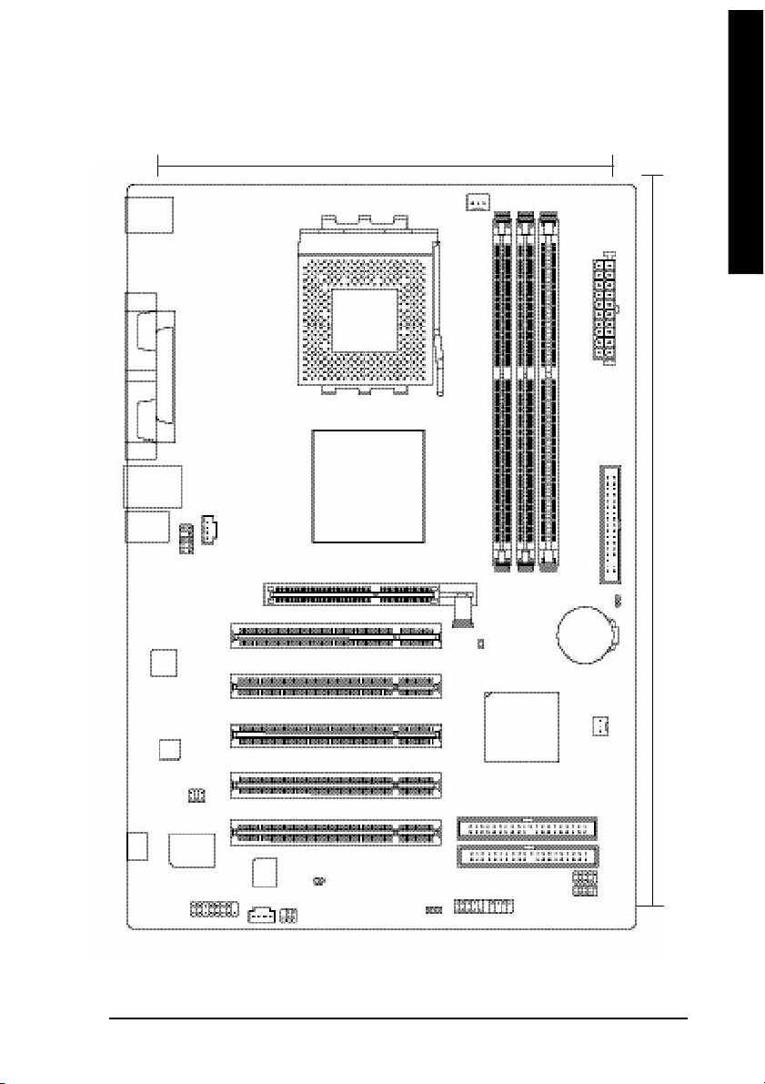
7VT600-RZ Series Motherboard Layout
20.0 c m
KB_MS
USB
AUDIO
VT6 10 3L *
COMA
COMB
CODEC
LPT
LAN *
CD_IN
F_AUDIO
AGP
SOCKET A
VIA KT600
CPU_FAN
PCI1
PCI2
PCI3
PCI4
7VT600-RZ
DDR1
DDR2
JP1
VT8 2 35
DDR3
CLR_ CM OS
BATTERY
ATX
FD D
30.5 cm
SYS_FAN
SUR_C EN
-C
IT8 7 05
BIOS
GAME
AUX_IN
" * " Support 7 VT600-RZ on ly.
SPDIF_IO
PCI5
CI
PWR_LED
F_PANEL
F_U SB1
F_U SB2
- 7 -
IDE2
IDE1
Introduction
Page 8
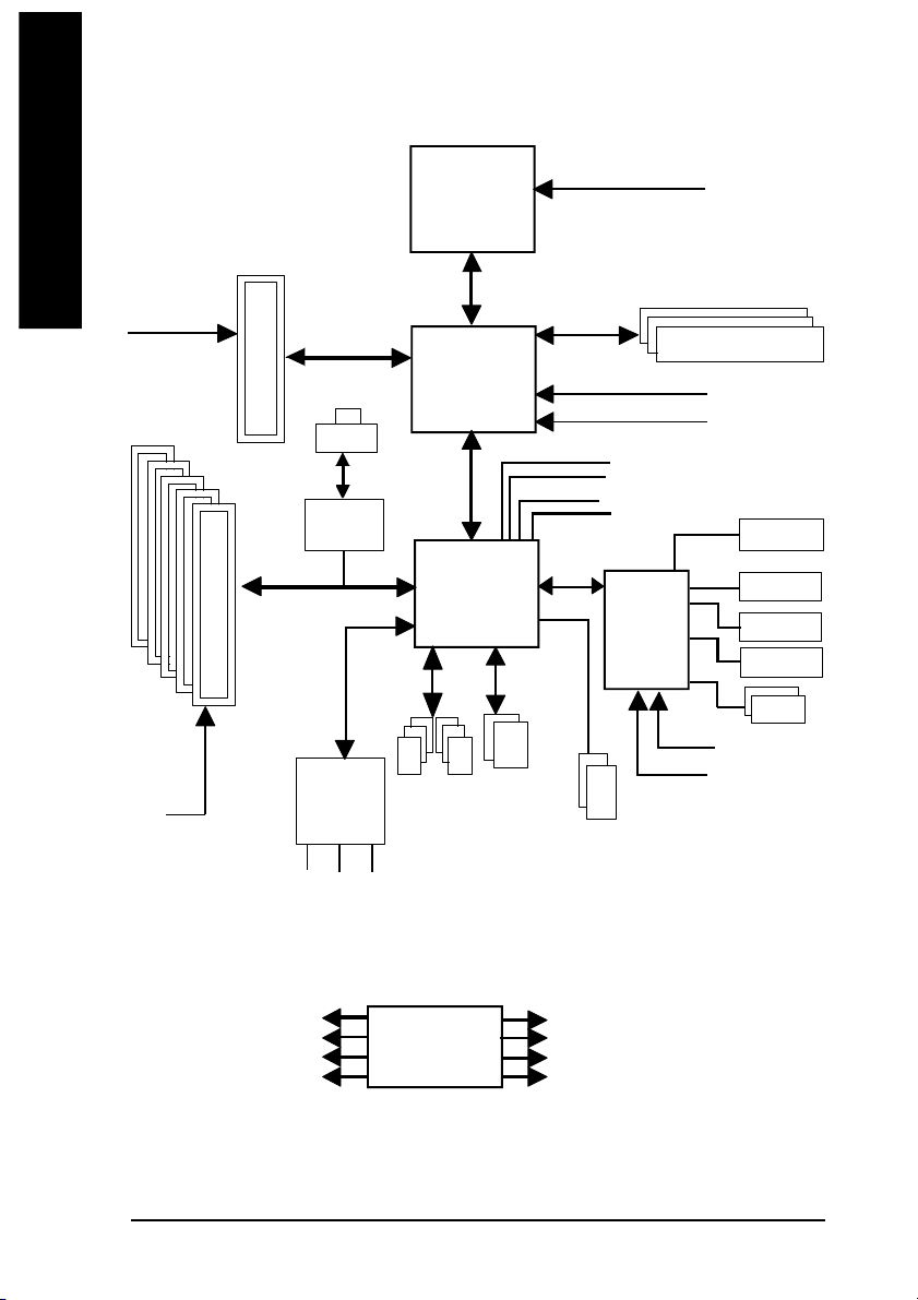
Block Diagram
English
5 P CI
AGPC LK
(66MHz)
AGP 4X/ 8X
RJ4 5*
VIA
VT6103L*
CPUCLK+/- (100/ 133/166/200M Hz)
TM
AMD-K7
System Bus1 00/133/166/20 0MHz
VIA
KT600
66MHz V_Link
HCLK+/- (100/133/166/200MHz)
GCLK(66MHz)
33 MHz
48 MHz
VCLK(66MHz)
14.318 MHz
DDR RAM
BIOS
AC97
PCICL K
(33MHz)
PCICLK (33M Hz)
USBCLK (48 MHz)
14.318 MHz
" * " Support 7 VT600-RZ on ly.
CODE C
MIC
33 MHz
AC97 Link
LINE-IN
LINE-OUT
6 U SB
Ports
CLK
GEN
VIA
VT8235
ATA66/10 0/133
IDE Channe ls
- 8 -7VT600-RZ Series M otherboard
Game Port
IT8705
24 MHz
33 MHz
PS/2 KB /Mou se
HCLK+/- (100/133/166/200MHz)
CPUCLK+/- (100/ 133/166/200M Hz)
AGPCLK (66M Hz)
V_Link (66M Hz) / GCLK (66MHz)
Flop py
LPT Port
2 COM
Por ts
Page 9
English
Hardware Installation Process
To set up your com puter, you m ust com plete the following steps:
Step 1- Set System Jum per (JP1)
Step 2- Install the Central Proces sing U nit (CPU)
Step 3- Install mem ory mo dules
Step 4- Install expans ion cards
Step 5- Install I/O Peripherals ca bles
Step 2
Step 3
Step 5
Step 5
Step 1
Step 4
Step 5
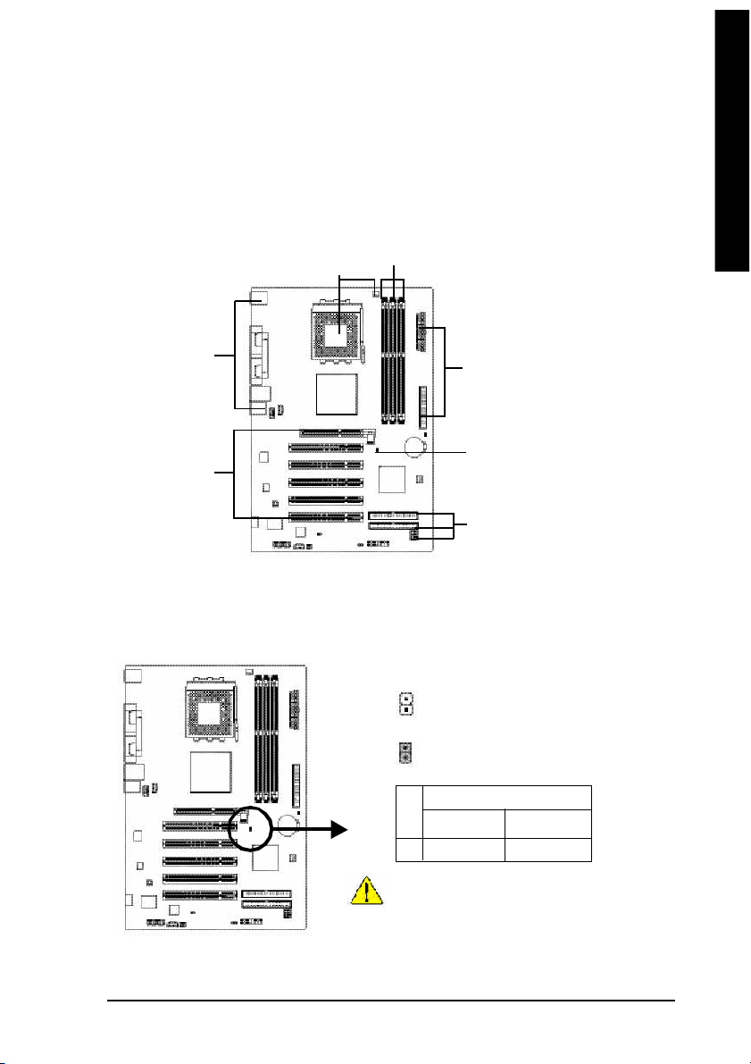
Step 1: Set System Jumper (JP1)
The system b us frequency can be switched at 100/133/166/200M Hz by adjusting system jumper (JP1).
(The internal frequency depend on C PU.)
Open: A uto
1
Close: 100MH z (Defualt)
1
JP1 CPU CLOCK
100MHz Auto
1-2 Clos e Open
100M Hz : Fix F SB 200M Hz CPU
Auto : Su pport FSB 266/333/4 00 M Hz CPU
The "J P1" mus t set to "Auto" when you are using
FSB 266/3 33/400M Hz C PU.
- 9 - Hardware Installation Proc ess
Page 10
Step 2: Install the Central Processing Unit (CPU)
English
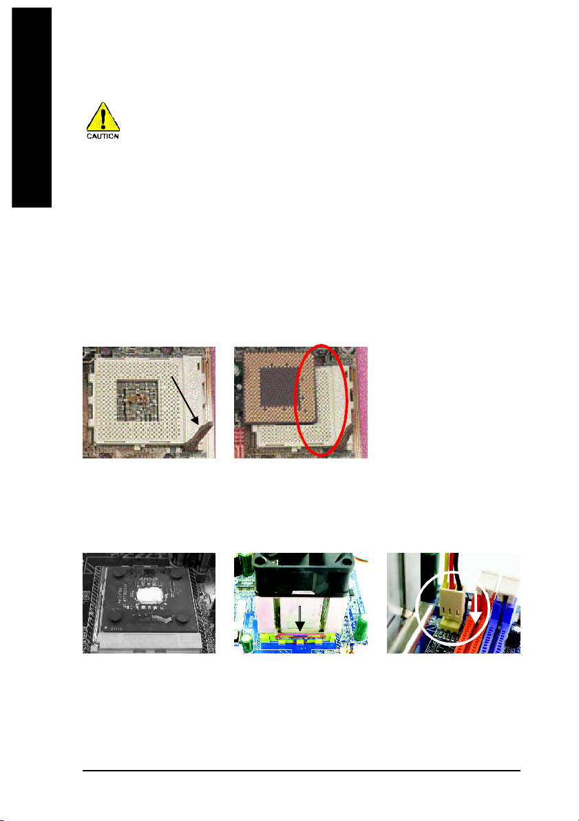
Step 2-1: CPU Installation
Figure 1.
Pu ll th e ro d to the 90 -de gr ee
dire ctly.
Before installing the p rocessor, adh ere to the following warning:
1. Please m ake sure the CPU type is supported by the mo therboard.
2. The proces sor will over heat without the heatsink and/o r fan, resulting in perma nent
irreparable damage.
3. If you do not m atch the CPU soc ket Pin 1 a nd CPU cut edge well, it will cau se
improper i nstallation. Please change the insert orientation.
4. Apply therm al grease between the process or and c ooling fan.
5. Never run the process or without the hea tsink properly and firmly attached. Perman ent
dam age will result.
6. Please set the CPU host frequen cy i n accord ance with your p rocessor 's speci fications.
We don't recom men d you to set the system b us frequency over the CPU's specification
because these specific bus frequenc ies are not the standard specifications for CPU,
chipset and m ost of the peripherals. Wh ether your sys tem can run under these spec ific
bus frequenci es pro perly will depe nd on your hardware c onfigurations, i ncluding C PU,
Me mory , Card s… etc.
Socket Actuation Lever
Figure 2.
Locate Pin 1 in the socket and look
for a (golden) cut edge on the CPU
uppe r c orner . Insert the CPU into
the socket. (Do not force the CPU into the socket.) The n m ove the
sock et le ver to the lock ed po sition while ho lding p ressu re on the
center of the C PU.
Step 2-2: CPU Cooling Fan Installation
Figure 1.
Apply the thermal tape(or grease)
to provide better heat conduction
betwee n you r CPU and co olin g
fan.
Figure 2.
Fasten the coolin g fan su pporting -bas e onto the CPU s ocke t
on the motherboard.
- 10 -7VT600-RZ Series M otherboard
Figure 3.
Make sure the CPU fan is plugged
to the CPU fan c onnec tor, than
the install co mpletely.
Page 11
English
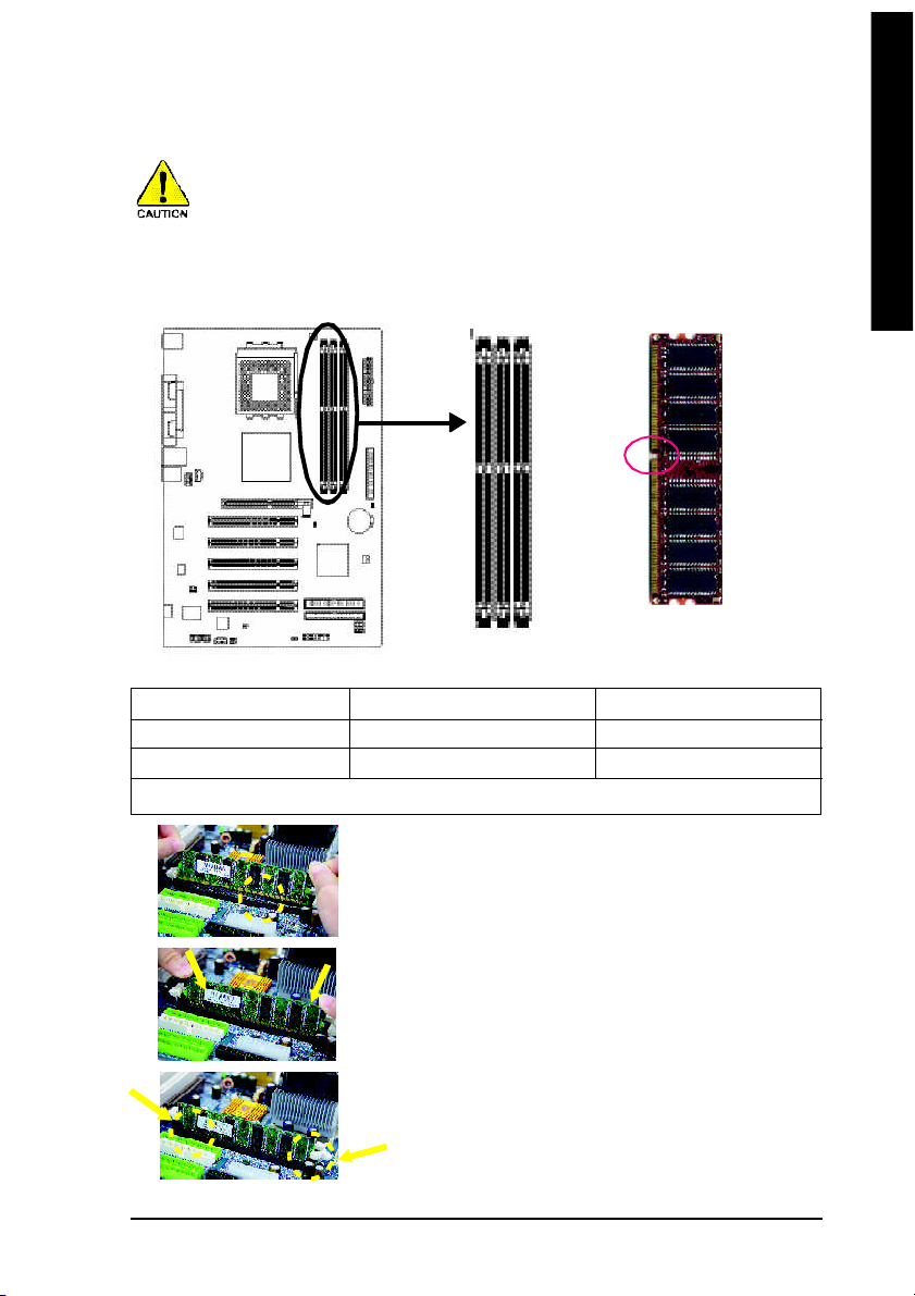
Step 3: Install Memory Modules
Before installing the m em ory mod ules, adhere to the following warning:
1. When DIMM LED is ON, do not install / rem ove DIMM from socket.
2. Please note that the DIMM module can only fit in one direction due to the one notch. Wrong
orientation will cause imp roper installation. Please change the insert orientation.
The motherboard has 3 dual inline m em ory module (DIMM) sockets. The BIOS will automatically detects
mem ory type and size. To install the mem ory module, just push it vertically into the DIMM socket. The
DIMM mod ule c an only fit in one direction due to the notch. Mem ory size ca n vary between sockets.
Notch
DDR
Support Unbuffered DDR DIMM Sizes type:
64 Mbit (2Mx8x4 banks) 64 Mbit (1Mx16x4 banks) 128 Mbit(4Mx8x4 banks)
128 Mbit(2Mx16x4 banks) 256 Mbit(8Mx8x4 banks) 256 Mbit(4Mx16x4 banks)
512 Mbit(16Mx8x4 banks) 512 Mbit(8Mx16x4 banks)
Total System Memory (Max3GB)
1. The DIMM soc ket has a notch , so th e DIM M
mem ory m odule can only fit in one direction.
2. Inser t the DIM M m emo ry mo dule v ertically in to
the DIMM sock et. Then push it down.
3. Close the plastic clip at both edges o f the DIMM
sockets to lock the DIMM m odule.
Rever se the ins tallation steps whe n y ou wish to
remove the DIMM module.
- 11 - Hardware Installation Proc ess
Page 12
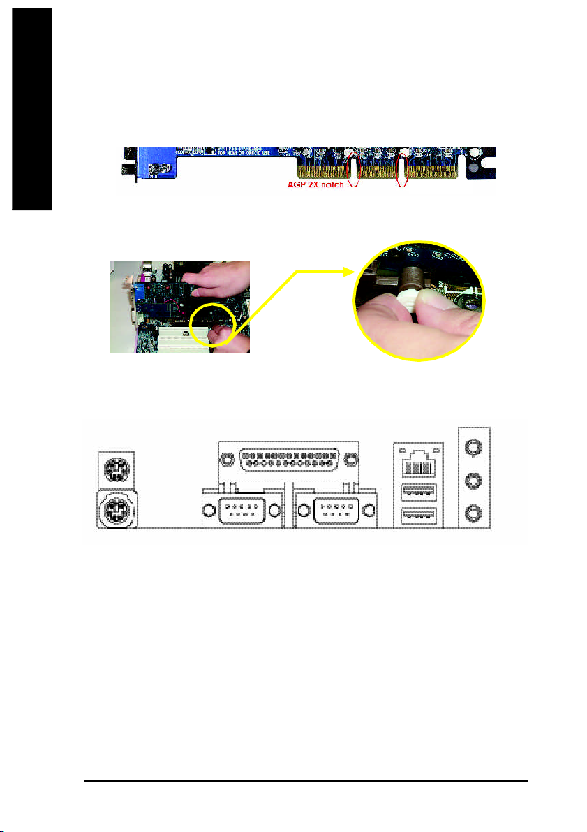
Step 4: Install Expansion Cards
1. Read the related expansion car d's instruction document before install the expans ion card into
English
2. Please m ake s ure your A GP ca rd is AGP 4X/8X (1.5V).
3. Please carefully pull out the smal l white- dra wable bar at the e nd of the AGP slot when you try to
Step 5: Install I/O Peripherals Cables
the computer.
AGP 4X/8X notch
install/ Uninstall the AGP card. Ple ase align the AGP card to the onb oard AGP slot and press firm ly
down on the slot .M ake sure your AGP card is locked by the sm all white- drawable bar.
AGP Card
Step 5-1: I/O Back Panel Introduction
u
v
w
u PS/2 Keyboard and PS/2 Mouse connector
This conne ctor supports standard P S/2 keyboard and P S/2 mo use.
v Parallel port (LPT)
Device like pr inter can be conn ected to Parallel port.
w/x Serial ports (COMA / COMB)
Mouse and modem etc. can be connected to Serial port.
y LAN port *
LAN is fast Ethernet with 10/100M bps spe ed.
z USB port
Before you connec t your device (s) i nto USB connec tor(s), p lease m ake su re yo ur device (s)
such as USB keyboard , m ouse, scanner, zip, speaker. ..etc. Have a standar d USB interface.
Also m ake sure your OS supports US B controller. If your OS does not support USB controller,
please contact OS vendor for possible patch or driver upgrade. For m ore information please
contact your OS or d evice(s) vendor s.
" * " Support 7 VT600-RZ on ly.
- 12 -7VT600-RZ Series M otherboard
y
z
x
y
{
|
}
Page 13

English
Line In jack
{
Devices like CD-ROM , walkm an etc. can be conn ect to Line In jack.
|
Line Out jack
Connect the stereo speakers or ear phone to this connector.
MIC In jack
}
Micr ophone can be connec t to MIC In jack.
After installation of the audio driver, you are ab le to use 2/4 /6-channel au dio feature by software
selection. You can conn ect "Front speaker" to "Line Out" jack, Conn ect "Rear speaker" to "Line In"
jack and conne ct "Center/Subwoofer" to "MIC In" ja ck.
Step 5-2 : Connectors Introduction
1
3
9
11
10
15
1) CPU_FAN
2) SYS_FAN
3) ATX (ATX Power)
4) IDE1 / IDE2
5) FDD
6) PWR_LED
7) F_PANEL
8) BATTERY
9) F_AUDIO
13
12 6 716
5
17
8
2
4
14
10) SUR_CEN
11) CD_IN
12) AUX_IN
13) SPDIF_IO
14) F_USB1 / F_USB2
15) GAME
16) CI (Case Open)
17) CLR_CMOS
- 13 - Hardware Installation Proc ess
Page 14

1) CPU_FAN (CPU FAN Connector)
English
2) SYS_FAN (System FAN Connector)
Please note, a proper installation of the CPU coo ler is essential to prevent the CPU from run ning
under abnorm al condition or dam aged by overheating.The C PU fan connector supports M ax.
current up to 600 mA.
Pin No. Definition
1
1 GND
2 +12V
3 Sense
This c onnector allows yo u to li nk with the cooli ng fan on the system c ase to lower the system
temperature.
Pin No. Definition
1 GND
2 +12V
1
3 Sense
3) ATX (ATX Power Connector)
AC power cord s hould only be con nected to your power suppl y un it after ATX power cable and
other related devices are firmly connected to the mainboard.
1 0
1
Pin No . De finition
2 0
1 3.3V
2 3.3V
3 GND
4 VCC
5 GND
6 VCC
7 GND
8 Power Good
1 1
9 5V SB (stand by +5V)
10 +12V
- 14 -7VT600-RZ Series M otherboard
Pin No . De finition
11 3.3V
12 -12V
13 GND
14 PS_O N(soft on/off)
15 GND
16 GND
17 GND
18 -5V
19 VCC
20 VCC
Page 15

English
4) IDE1/ IDE2(IDE1/IDE2 Connector)
Please connec t first harddisk to IDE1 and conne ct CDROM to IDE2. The red stripe of the ribbon
cable m ust be the same s ide with the Pin1.
1
IDE2
IDE1
2
3 9
4 0
5) FDD (Floppy Connector)
Please conne ct the floppy drive ribbon ca bles to FDD. It supports 360K, 720K,1.2M ,1.44M and
2.88M bytes floppy d isk types. The red stripe of the ribbon cable m ust be the same side with the
Pin1.
3 4
3 3
2
1
6) PWR_LED
PWR_LE D is connect with the sy stem power indic ator to ind icate whether the sy stem is on/off. It
will blink when the system enters sus pend mod e. If you us e du al colo r LED, power LED will turn
to another color.
Pin No. Definition
1
1 MPD+
2 MPD3 MPD-
- 15 - Hardware Installation Proc ess
Page 16

7) F_PANEL (2 x 10 pins Connector)
Please connect the power LED, PC speak er, reset switch and p ower switch etc. of y our chassis front
panel to the F_PANEL connector acco rding to the pin assignm ent below.
English
Messa ge L ED/
Po wer/
Slee p LED
Sof t Po wer
Connect or
PW+
MSG+
PW-
MSG-
1 1
2
1
1
1
HD-
RES+
HD+
RES-
Res et Swi tch
IDE H ard Disk Acti ve LE D
HD (IDE Hard Disk Active LED) Pin 1: LED anode(+)
Pin 2: LED cathode(-)
SPK (Speaker Connector) Pin 1: VCC(+)
Pin 2- Pin 3: NC
Pin 4: Data(-)
RST (Reset Switch) Open: Normal Operation
Close: Reset Hardware System
PW (Soft Power Connector) Open: Normal Operation
Close: Power On/Off
MPD(Message LED/Power/ Pin 1: LED anode(+)
Sleep LED) Pin 2: LED cathode(-)
NC NC
Speak er Co nnector
SPEAK+
1
NC
SPEAK-
2 0
1 9
8) BATTERY (Battery)
CAUTION
Da nge r of ex plo si on if b atter y is inco rr ectl y
+
replaced.
Repla ce only with the sa me or equiv alent type
recomm ended by the manufacturer.
Di sp ose of use d batter ie s ac cor di ng to the
manufacturer's instructions.
If you want to erase CM OS...
1. Turn off the computer and unplug the power cord.
2. Rem ove the battery, wait for 30 second.
3. Re-in stall the battery.
4. Plug the power cord and turn on the com puter.
- 16 -7VT600-RZ Series M otherboard
Page 17

English
9) F_AUDIO (Front Audio Connector)
If you want to use Front Audio connector, you m ust remov e 5-6, 9-10 Jum per.
In order to utilize the front audio header, yo ur chassis must have front audio connector. Also p lease
make sure the pin assigment on the cable is the same as the pin assigment on the MB header. To find
out if the chassis you are buy ing support front audio co nnector, please contact your dealer. Pl ease
note, you can hav e the alternative of using front a udio connector or of using rear a udio connector to
play soun d.
Pin No. Definition
1 MIC
9
1 0
2
1
2 GND
3 REF
4 Power
5 Front Audio (R)
6 Rear Audio (R)
7 Reserved
8 No Pin
9 Front Audio (L)
10 Rear Audio (L)
10) SUR_CEN (Surround Center Connector)
Please co ntact your neare st dealer for optional SUR_CEN cab le.
Pin No. Definition
6
2
1
5
1 SUR OUTL
2 SUR OUTR
3 GND
4 No Pin
5 CENTER_OUT
6 BASS_OUT
11) CD_IN (CD In Connector)
Connect CD-ROM o r DVD-ROM a udio out to the connector.
1
- 17 - Hardware Installation Proc ess
Pin No. Definition
1 CD-L
2 GND
3 GND
4 CD-R
Page 18

12) AUX_IN ( AUX In Connector)
English
13) SPDIF_IO (SPDIF In/Out Connector)
Connect other devi ce (such as PC I TV Tunner au dio out)to the connector.
Pin No. Definition
1
1 AUX-L
2 GND
3 GND
4 AUX-R
The SPDIF output is capable of providing digital audio to external speakers or compressed AC3 data
to an external Dolby Digital Decoder. Use this feature only when your stereo system has digital input
and output function. Us e SPDIF in feature on ly when your device ha s digi tal ou tput function. Be
careful with the pola rity of the SPDIF_IO connector. Check the pin assignm ent carefully while you
conn ect the SPDIF cable , inc orrect conn ection between the ca ble and conne ctor wil l m ake the
devic e unable to work or even d ama ge it. For optional S PDIF c able, plea se contact you r local
dealer.
1625
Pin No. Definition
1 VCC
2 No Pin
3 SPDIF
4 SPDIFI
5 GND
6 GND
- 18 -7VT600-RZ Series M otherboard
Page 19

English
14) F_ USB1 / F_USB2 (Front USB Connector)
Be careful with the polari ty of the F_USB c onnector. Check the pin assi gnment care fully while you
conne ct the F_ USB cable , inco rrect connec tion between the cabl e a nd con nector will m ake the
devic e u nable to work o r e ven da mag e i t. For optional F_USB cable, pl ease contact yo ur local
dealer.
Pin No. Definition
1 0
2
9
1
1 Power
2 Power
3 USB0 DX-/USB2 DX4 USB1 Dy-/USB3 Dy5 USB0 DX+/USB2 DX+
6 USB1 Dy+/USB3 Dy+
7 GND
8 GND
9 No Pin
10 NC
15) GAME (Game Connector)
This co nnector suppo rts j oystick, M IDI keybo ard and other re late aud io devi ces. Che ck the pin
assig nme nt while y ou connec t the gam e ca bles. Plea se con tact your neares t deal er for optional
gam e cables.
Pin No. Definition
1 VCC
2
1
1 6
1 5
2 GRX1_R
3 GND
4 GPSA2
5 VCC
6 GPX2_R
7 GPY2_R
8 MSI_R
Pin No. Definition
9 GPSA1
10 GND
11 GPY1_R
12 VCC
13 GPSB1
14 MSO_R
15 GPSB2
16 No Pin
16) CI (Chassis Intrusion, Case Open)
This 2 -pin con nector allows your system to enable or dis able the "c ase open " item in B IOS if the
system case begin rem ove.
Pin No. Definition
1
- 19 - Hardware Installation Proc ess
1 Signal
2 GND
Page 20

17) CLR_CMOS (Clear CMOS)
English
You may clear the CM OS data to its default values by this jumper. To clear CMOS , temporarily shor
1-2 pin. Default doesn't include the "Shunter" to prevent from imp roper use this jumper.
Short: Clear CM OS
1
Open : Norm al
1
- 20 -7VT600-RZ Series M otherboard
Page 21

Chapter 2 BIOS Setup
BIOS Se tup is an ov ervie w of the BIOS Setup Progr am. Th e prog ram that al lows use rs to mod ify the
basic system co nfiguration. This type of inform ation is stored in battery-backed CMOS RAM so that it
retains the Setup informa tion when the po wer is turned off.
ENTERING SETUP
Powering ON the com puter and pressing <Del> immediately will allow you to enter Setup. If you require
m o re ad v an c ed BIO S settings, please go to "Advanced BIO S" setting men u. To enter
Advan ced B IOS se tting me nu, p ress " Ctrl+F1" ke y on the BIOS scree n.
CONTROL KEYS
< >< >< >< > M ove to se lect item
<Enter> Select Item
<Esc > Ma in M enu - Q uit an d not save changes into CM OS Status Page S etup Me nu
and Option Page Setup M enu - Exit cur rent page and return to Ma in M enu
<+/P gUp> Incre ase the nu mer ic val ue or m ake ch anges
<-/PgDn> Decrea se the num eric value or make changes
<F1> General help, o nly for Status Pa ge Setup M enu and Option Page Setup M enu
<F2> Item Help
<F5> Restore the previous CM OS value from CMOS, only for Option Page Setup Menu
<F6> Load the file- safe de fault CMOS value from B IOS default table
<F7> Load the Op timized D efaults
<F8> Q-Fl ash utili ty
<F9> System Inform ation
<F10> Save all the CM OS ch anges , o nly for M ain M enu
Main Menu
The on -line d escription of the hig hlighted s etup function is disp layed a t the b ottom o f the s creen.
Status Page Setup Menu / Option Page Setup Menu
Press F1 to pop up a sm all h elp window that desc ribes the a ppropr iate key s to u se and the possib le
selec tions for the high lighted i tem. T o e xit the Help Windo w pres s <Esc >.
English
The Main Menu (For example: BIOS Ver. : F4c)
Once you enter Award BIOS CM OS Setup U tility, the Ma in M enu ( as figure be low) will ap pear on the
scr een. T he M ain Menu allows you to select from eight setup functions and two exit choices. Use
arrow ke ys to s elect am ong the items and press <Enter> to a ccept or enter the s ub-m enu.
CMOS Setu p Utili ty-Co pyrig ht (C ) 198 4-200 4 Award Soft ware
} Stan dard CMOS Fe atur es
} Adva nced BIOS Fe atur es
} Inte grat ed P erip hera ls
} Powe r Man agem ent Set up
} PnP/ PCI Conf igur atio ns
} PC H ealth St atus
} Freq uency /Volt age Con trol
ESC: Qu it higf: Select Item
F8: Q-Fla sh F10: Save & Exit Set up
Time , Dat e, Har d Disk Type. ..
Load Fail -Safe D efaul ts
Load Opti mized D efaul ts
Set Super visor P asswo rd
Set U ser Pass word
Save & Exit S etup
Exit Witho ut Savi ng
BIOS Setup- 21 -
Page 22

If you can't find the setting you want, please press "Ctrl+F1" to search the advanced
option hidden.
English
• Standard CMOS Features
• Advanced BIOS Features
• Integrated Peripherals
• Power Management Setup
• PnP/PCI Configuration
• PC Health Status
• Frequency/Voltage Control
• Load Fail-Safe Defaults
• Load Optimized Defaults
• Set Supervisor Password
• Set User Password
• Save & Exit Setup
• Exit Without Saving
This s etup page includes al l the item s in standard com patible BIOS.
This setup page i nclude s all the item s of Award specia l e nhance d features.
This se tup page incl udes all onbo ard perip herals.
This s etup page incl udes all the items of Gree n function features.
This setup pag e i nclude s all the configu rations of PCI & P nP ISA resou rces.
This setup p age is the System a uto detect Tem perature, voltage, fan, s peed.
This setup page is co ntrol CPU clock and freque ncy ra tio.
Fail-Sa fe Defaults indicates the value of the sys tem param eters which the system would be in s afe
configuration.
Optim ized Defaults indi cates the value of the system p aram eters which the sys tem woul d b e in
best performa nce configuration.
Chan ge, s et, o r dis able password. It allows you to li mi t access to the system and Setup, or just
to Setup.
Chan ge, set, or d isab le pass word. It allo ws you to l im it ac cess to the sys tem.
Save CM OS val ue se ttings to CM OS an d exit se tup.
Aband on al l C MOS value chan ges an d e xit setup.
7VT600-RZ Series M otherboard
- 22 -
Page 23

Standard CMOS Features
CMOS Setu p Utili ty-Co pyrig ht (C ) 198 4-200 4 Award Soft ware
Date (mm :dd: yy) Fri, Jan 9 2004
Time (hh :mm: ss) 22: 31:2 4
} IDE Pri mary Ma ster [No ne]
} IDE Pri mary Sla ve [No ne]
} IDE Sec ondary M aster [ None ]
} IDE Sec ondar y S lave [No ne]
Driv e A [1.44M, 3.5 "]
Driv e B [None ]
Flopp y 3 Mode Supo rt [Dis able d]
Holt On [All, B ut Keybo ard]
Base Memo ry 640K
Exte nded Mem ory 127M
Tota l Me mory 128M
higf: Mov e En ter: Sele ct +/ -/PU /PD: Val ue F10: Sa ve ESC: Ex it F1: Gener al Help
F5: Previo us Valu es F6: F ail-Sa ve Defau lt F7 : Op timiz ed Defa ults
FDate
The date format is <week>, <month>, <day>, <year>.
8Week The week, from Sun to Sat, determin ed b y the BIOS and is display o nly
8Month The m onth, Jan. Throu gh Dec.
8Da y The day, from 1 to 31 (or the maxim um allowed in the m onth)
8Year The year, from 1999 through 2098
FTime
The times format in <hour> <min ute> <second>. The time is calculated base on the 24-hour mi litarytime clo ck. For exam ple, 1 p.m . is 13:00: 00.
Stan dard CMOS Fe atur es
Item He lp
Menu Leve l}
Chan ge th e day, mont h,
year
<We ek>
Sun. to Sat.
<Mon th>
Jan. to Dec.
<Day>
1 to 31 (or maxim um
allow ed in th e mont h)
<Ye ar>
1999 to 2098
English
FIDE Primary Master, Slave / Secondary Master, Slave
The category identifies the types of hard dis k from driv e C to F that has been installed in the
comp uter. There are two types: auto type, and m anual type. Manual type is user -definable; Auto
type which will a utomatica lly detect HDD type.
Note that the specifications of your drive must match with the dri ve table. The hard d isk will not work
properly if you enter improper information for this category.
If you select User Type, related informa tion will be ask ed to enter to the following item s. E nter the
information directly from the keyb oard and press <Enter>. Such information should be provided in
the documentation form your hard dis k vendor or the system m anufacturer.
8Ca paci ty: The hard disk siz e. The unit is Mega Bytes.
8Acces s M ode: The options are: Auto / Large / LBA / Norm al.
8Cyli nder : The cylind er numb er of hard d isk.
8Head The read / Write head number of hard disk.
8Precomp The cyliner num ber a t which the disk driver change s the write curre nt.
8Landing Zone The cylinder num ber that the disk driver heads(read/write) are seated when
the disk drive is park ed.
8SE CTOR S The s ector number of each track define on the hard disk.
If a hard disk ha s not been ins talled select NONE and press <Enter>.
BIOS Setup- 23 -
Page 24

FDrive A / Drive B
computer.
English
FFloppy 3 Mode Support (for Japan Area)
FHalt on
The category identifies the types of floppy disk drive A or driv e B that has bee n installed in the
8None No floppy drive installed
8360K, 5.25 “. 5. 25 inch PC-type standard drive ; 360K byte cap acity.
81.2M, 5.25 ”. 5. 25 inch AT-type high-den sity dri ve; 1.2M byte capacity
(3.5 inch when 3 M ode is Enabled).
8720K, 3.5 “. 3.5 inc h dou ble-sided drive; 7 20K b yte capacity
81.44M, 3.5 “. 3.5 inc h do uble-side d drive; 1.44M byte ca pacity.
82.88M, 3.5 “. 3.5 inc h do uble-side d drive; 2.88M byte ca pacity.
8Disabled Nor mal F loppy Driv e. (D efault value)
8Drive A Enabled 3 mod e function of Drive A.
8Drive B Enabled 3 mod e function of Drive B.
8Both Dri ve A & B are 3 mode Floppy Drives.
The category determines whether the computer will stop if an error is detected during power up.
8NO Erro rs The system boot will not stop for any erro r that may be detected
and you will be prom pted.
8All Err ors Whenever the BIOS detects a non-fatal error the system will be stopped.
8All, B ut Keybo ar The sys tem boot will not stop for a keyb oard erro r; i t will stop for
all other errors. (Default value)
8All, But Diskette The sys tem boot will not stop for a disk err or; it will s top for all
other errors.
8All, But Disk /Key Th e system boo t will not stop for a keybo ard or disk error; it will
stop for all other errors.
Memory
The ca tegory i s displa y-only which is determ ined by P OST (Po wer On S elf Test) of the BIOS.
Base Memory
The POST of the BIOS will determ ine the am ount of base (or co nventional) me mory
installed in the system .
The va lue of the base mem ory is typically 512 K for systems with 512 K memory
installed on the m otherboard, or 640 K for systems with 640 K or more memory
installed on the motherboard.
Extended Memory
The BIOS d etermines how m uch extended mem ory is p resent during the POST.
This is the amou nt of m emory located abo ve 1 M B in the CPU memory address
map.
7VT600-RZ Series M otherboard
- 24 -
Page 25

Advanced BIOS Features
English
CMOS Setu p Utili ty-Co pyrig ht (C ) 198 4-200 4 Award Soft ware
First Boo t Dev ice [Flopp y]
Second Boot Device [HDD-0]
Third Boo t Dev ice [CDRO M]
Passw ord Che ck [Setu p]
higf: Mov e En ter: Sele ct +/-/ PU/P D: V alue F1 0: Save ESC: Ex it F1 : Gen eral He lp
F5: Previo us Valu es F6: F ail-Sa ve Defau lt F7: Optim ized De faul ts
Adva nced BIOS Fe atur es
Item He lp
Menu Leve l}
Sele ct Bo ot Devi ce
pri orit y
[Fl oppy ]
Boot from fl oppy
[LS1 20]
Boot from L S120
[HDD -0]
Boot from Fi rst H DD
[HDD -1]
Boot from Sec ond H DD
FFirst / Second / Third Boot device
M This feature allows yo u to sel ect the boo t device priority.
8Flo ppy Selec t your boot devic e p riority b y Fl oppy.
8LS120 Select your boo t device priority by LS1 20.
8HDD-0~3 Select your boot devic e priority by HDD-0 ~3.
8SCS I Se lect your bo ot device priority by SCSI.
8CDROM Se lect your boot device priori ty by CDROM .
8LAN Selec t your boot devic e p riority by LA N.
8USB-CDR OM Select yo ur b oot device pr iority by USB- CDROM .
8USB-Z IP Selec t your boot devic e p riority by USB -ZIP.
8USB-FDD Se lect your boot devic e pr iority by USB-FD D.
8USB-HDD Select your boot dev ice priority by USB-H DD.
8ZIP Select your boot device prio rity by ZIP.
8Disabled Disabled this function.
F Password Check
8Sys tem The system can not boot and can not acces s to Setup page will be den ied
if the correct password is no t entered at the prompt.
8Setup The system will boo t, but acces s to Setup will b e de nied if the correct
password is not entered at the prom pt. (Default value)
BIOS Setup- 25 -
Page 26

Integrated Peripherals
English
F OnChip IDE Channel0
MWhen enable d, all ows yo u to use the on board prim ary P CI IDE. If a ha rd dis k c ontroller card is
used, set at Dis abled.
F OnChip IDE Channel1
MWhen enable d, all ows yo u to use the on board secon dary P CI IDE. If a ha rd dis k c ontroller card
is us ed, s et at Di sable d.
F AC97 Audio
F VIA Onboard LAN *
F USB 1.1 Controller
MDisabl e this option if you are not usi ng the onboard USB feature.
F USB 2.0 Controller
MDisabl e this option if you are not usi ng the onbo ard USB 2.0 feature.
" * " For 7VT600 -RZ-C on ly.
7VT600-RZ Series M otherboard
CMOS Setu p Utili ty-Co pyrig ht (C ) 198 4-200 3 Award Soft ware
OnChip IDE C hannel0 [Enable d]
OnChip IDE C hannel1 [Enable d]
AC97 Audio [Aut o]
VIA O nboar d L AN * [Ena bled ]
USB 1.1 Con troller [Enable d]
USB 2.0 Con troller [Enable d]
USB Keyb oard Support [Disa bled]
USB Mouse Supp ort [Disa bled]
VIA LAN Boot ROM * [Disa bled]
Onboard Serial Port 1 [3F8/IRQ 4]
Onboard Serial Port 2 [2F8/IRQ 3]
Onboard Parallel Port [378/IRQ 7]
UART Mod e Sel ect [Norma l]
Paralle l Port Mode [SPP]
Game Port Addr ess [201]
Midi Port Addr ess [330]
Midi Port IRQ 10
higf: Mov e En ter: Sele ct +/-/ PU/P D: V alue F1 0: Save ESC: Ex it F1 : Gen eral He lp
F5: Previo us Valu es F6: F ail-Sa ve Defau lt F7: Optim ized De faul ts
Inte grat ed P erip hera ls
Item He lp
Menu Le vel u
8Enabled Enable onboard 1st channel IDE por t. (Default value)
8Disabled Disable onboard 1st chann el IDE port.
8Enabled Enable onboard 2n d channel IDE port. (De fault value)
8Disabled Disable onboard 2nd chann el IDE port.
8Enabled BIOS will autom atically detect onbo ard AC97 Audio. ( Default valu e)
8Disabled Disab led AC9 7 Audi o.
8Enabled Enable VIA Onboar d LAN function. (D efault value)
8Disabled Disabl e this function.
8Enabled Enable d USB Co ntroller. (Default valu e)
8Disabled Disab led USB Co ntroller.
8Enabled Enabl ed USB 2.0 Controlle r. (De fault value)
8Disabled Disabl ed USB 2.0 Controlle r.
- 26 -
Page 27

F USB Keyboard Support
MWhen a USB keyboard is in stalled, please s et at Enable d.
8Enabled Enabl ed USB Key board Suppor t.
8Disabled Disabl ed USB Keyboa rd Supp ort. (Default valu e)
F USB Mouse Support
8Enabled Enable d USB M ouse Su pport.
8Disabled Disabl ed USB Mou se S upport. (D efault value)
F VIA LAN Boot ROM *
This function decide whether to invoke the boot RO M of the onb oard LAN chip.
8Disabled Disable this function. (Default Value)
8Enabled Enable this function.
F Onboard Serial Port 1
8Auto BIOS will autom atically setup the port 1 addr ess.
83F8/ IRQ4 Enable onboar d Seria l p ort 1 and a ddress is 3F8, Using IRQ4. (D efault value)
82F8/ IRQ3 Enable onboar d Seria l po rt 1 and ad dress is 2F 8,Using IRQ3.
83E8/ IRQ4 Enable onboar d Seria l po rt 1 and ad dress is 3E 8,Using IRQ4.
82E8/ IRQ3 Enable onboar d Seria l po rt 1 and ad dress is 2E 8,Using IRQ3.
8Disabled Disable onboard S erial port 1.
F Onboard Serial Port 2
8Auto BIOS will autom atically setup the port 2 addr ess.
83F8/ IRQ4 Enable onboar d Seria l po rt 2 and ad dress is 3F 8,Using IRQ4.
82F8/ IRQ3 Enable onboard Serial port 2 and addre ss is 2 F8,Using IRQ3. (Default Value)
83E8/ IRQ4 Enable onboar d Seria l po rt 2 and ad dress is 3E 8,Using IRQ4.
82E8/ IRQ3 Enable onboar d Seria l po rt 2 and ad dress is 2E 8,Using IRQ3.
8Disabled Disable onboard S erial port 2.
F OnBoard Parallel port
MThis feature allo ws you to selec t from a giv en set of param eters if the parallel port uses the
onboard I/O co ntroller.
8378/ IRQ7 En able onb oard LPT por t and addre ss is 37 8, U sing IRQ7.( Default Value)
8278/ IRQ5 En able on board L PT p ort and add ress is 27 8,Using IRQ5.
83BC /IRQ7 En able o nboard LPT port and addre ss is 3BC,Using IRQ7.
8Disabled Disable o nboard paral lel port.
English
F UART Mode Select
This item allows you to de termin e which Infra Red(IR) function of Onbo ard I/O chi p.
Normal Set onboard I/O chip UART to Normal M ode. (Default Value)
IrDA Set onboard I/O chip UART to IrDA M ode.
ASKIR Set onboa rd I/O chip UART to AS KIR Mode.
SCR Set onboard I/O chip as Smart Card interface.
" * " For 7VT600 -RZ-C on ly.
BIOS Setup- 27 -
Page 28

F Parallel Port Mode
MTh is feature al lows yo u to conne ct with an advan ced p rint via the port m ode it su pports.
English
F Game Port Address
F Midi Port Address
F Midi Port IRQ
Power Management Setup
8SPP Using P arallel por t as Standard Pa rallel P ort using IRQ7. (Default Value)
8EPP Using Parall el p ort as Enh anced Paralle l P ort IRQ5.
8EC P Using Paral lel p ort as Extended Capa bilities Port u sing IRQ7.
8ECP +EP P Using Para llel port as ECP & E PP m ode.
8Disabled Disabl ed this function.
8201 Set Game Po rt Addre ss to 20 1. (Default Value)
8209 Set Game Port Ad dress to 20 9.
8Disabled Disable d this function. (Default Value)
8300 Set Midi Port Ad dress to 30 0.
8330 Set Midi Port Ad dress to 33 0.
85 Se t 5 for M idi Port IRQ.
810 Se t 10 for Mi di Por t IRQ.(D efault v alue)
CMOS Set up U tility-Cop yright (C ) 1984-20 03 Aw ard Softw are
ACPI Susp end T ype [S1(POS )]
x USB Device Wake-Up From S3 Disabl ed
Power LE D in S1 state [Blinkin g]
Soft-Of f by PWRBTN [Instan t-off]
AC Back Funct ion [Soft -Off]
Keyboard Power On [Disa bled]
Mouse P ower On [Disa bled]
PME Event Wake Up [Enable d]
ModemRi ngOn/Wak eOnLAN [Enabled]
Resume b y Al arm [Disa bled]
x Date (of Month) Al arm Everyd ay
x Time (hh:mm:s s) Al arm 0 : 0 : 0
higf: Mov e En ter: Sele ct +/-/ PU/P D: V alue F1 0: Save ESC: Ex it F1 : Gen eral He lp
F5: Previo us Valu es F6: F ail-Sa ve Defau lt F7: Optim ized De faul ts
7VT600-RZ Series M otherboard
Power M anagemen t Se tup
Item He lp
Menu Lev el u
[S1]
Set sus pend type to
Power O n Su spend un der
ACPI OS
[S3]
Set sus pend type to
Suspend to R AM under
ACPI OS
- 28 -
Page 29

F ACPI Suspend Type
8S1(PO S) Se t suspen d type to Power On Susp end unde r ACPI OS(P ower On
Suspe nd). (D efault value)
8S3(S TR) Set suspend type to Suspend To RAM unde r ACPI OS (S uspend To RAM ).
F USB Device Wakeup From S3(When ACPI Suspend Type is set [S3(STR)])
USB devi ce wakeu p Fro m S3 can b e se t when ACPI stand by state set to S 3/ST R.
8Enabled USB Device can wak eup system from S3.
8Disabled US B De vice can’t wakeup s ystem from S 3. (D efault valu e)
F Power LED in S1 state
8Blin king In s tandby m ode(S 1), po wer LED will blink . (Default va lue)
8Dual/O ff In standby m ode(S1):
a. If u se s ingle co lor L ED, power LED will turn off.
b. If us e dua l colo r L ED, p ower LED will turn to a nother c olor.
F Soft-off by PWRBTN
8Instant-off Pres s power button the n Power off instan tly. (Default va lue)
8Dela y 4 Sec. Press power button 4 sec to Power o ff. En ter s uspend if button is pr essed
less than 4 sec.
F AC Back Function
8Me mo ry System power on depe nds o n the status befor e A C los t.
8Soft-Off Always in Off state when AC bac k. (Defau lt v alue )
8Full- On Always p ower on th e sys tem wh en AC ba ck.
F Keyboard Power On
This feature allows you to set the m ethod for powering -on the sys tem.
The option " Password" all ows you to set up to 8 alphanum eric characters to power-on the system.
The option "Key board 98" a llows you to use the stand ard keyb oard 98 to power on the system .
8P ass word Enter from 1 to 8 chara cters to se t the K eyboar d Power On Passwor d.
8Disabled Di sabled this function. ( Default value)
8Keyb oard 98 If you r keybo ard have "POWER Key" button, you can p ress the key to
power o n yo ur system .
English
F Mouse Power On
8Disabled Ca n't Po wer on sy stem b y M ouse E vent. (Defaul t va lue)
8Enabled Can P ower o n syste m by M ouse E vent.
F PME Event Wake up
When set a t Enabl ed, an y PCI-PM even t awakes the sy stem from a P CI-PM controlled state.
This feature requir es an ATX power s upply that pro vides at least 1A on the +5V SB lea d.
8Disabled Di sabled PM E Even t Wak e up func tion.
8Enabled Enable d PM E Even t Wake up function. (De fault Value)
BIOS Setup- 29 -
Page 30

F ModemRingOn/WakeOnLAN (When AC Back Function set to [Soft-Off])
English
F Resume by Alarm
You can en able wake on L AN feature by the "M odem RingO n/WakeOnLAN " or "PM E Even t Wake
up" when the M /B has "WOL" onboard connector. Only enabled the feature by "PME Event Wake
up". An incom ing cal l via mod em awakes the system from its soft-off m ode. When set at Enabl ed,
an inp ut signal c ome s from the other c lient.
Serv er on the LAN awaks the system from a so ft off state i f connec ted over LAN.
8Disabled Di sabled Mode m R ing On / W ake On LAN function.
8Enabled Enable d Mo dem Ring On / Wake On LAN function. ( Default Value)
You can set "Resum e by Alar m" item to e nable d a nd key in Data/tim e to power on system .
8Disabled Dis able this function. (Default Value)
8Enabled Enabl e alar m function to POWER ON system .
If RTC Al arm Lead To Power On is E nable d.
Date (of Month) Alar m : Eve ryd ay, 1 ~31
Tim e (hh : m m: ss) Alarm : (0~23) : (0~59) : (0~59)
PnP/PCI Configurations
CMOS Set up U tility-Cop yright (C ) 1984-20 03 Aw ard Softw are
PnP/PC I Confi guratio ns
PCI1/PC I5 IRQ Assignm ent [Aut o]
PCI2 IRQ As signment [Auto]
PCI3 IR Q Ass ignment [Aut o]
PCI4 IR Q Ass ignment [Aut o]
higf: Mov e En ter: Sele ct +/-/ PU/P D: V alue F1 0: Save ESC: Ex it F1 : Gen eral He lp
F5: Previo us Valu es F6: F ail-Sa ve Defau lt F7: Optim ized De faul ts
7VT600-RZ Series M otherboard
- 30 -
Item He lp
Menu Level u
Page 31

F PCI1/PCI5 IRQ Assignment
8Auto Auto as sign IRQ to PCI 1/ PCI 5. (Defau lt va lue)
83,4,5,7,9. ,10,11,12,14,15 Set 3,4,5,7, 9,10,11,12,14, 15 to PCI1/ PC I5.
F PCI2 IRQ Assignment
8Auto Auto assign IRQ to PCI 2. (Default val ue)
83,4,5,7,9. ,10,11,12,14,15 Set 3,4,5,7,9,10 ,11,12,14,15 to PCI2.
F PCI3 IRQ Assignment
8Auto Auto assign IRQ to PCI 3. (Default val ue)
83,4,5,7,9. ,10,11,12,14,15 Set 3,4,5,7,9,10 ,11,12,14,15 to PCI3.
F PCI4 IRQ Assignment
8Auto Auto assign IRQ to PCI 4. (Default val ue)
83,4,5,7,9. ,10,11,12,14,15 Set 3,4,5,7,9,10 ,11,12,14,15 to PCI4.
PCI Health Status
CMOS Set up U tility-Cop yright (C ) 1984-20 03 Aw ard Softw are
PC Healt h Sta tus
Rese t Cas e Open Stat us [Dis able d]
Case Open ed N o
Vcore 1.8 10V
DDR Vtt 1.2 48V
+3.3V 3.2 80V
+5V 4.9 19V
+12V 11.9 68V
5VSB 5.0 53V
Curr ent S ystem Te mpera ture 27oC
Curr ent C PU Temp eratu re 37oC
Curre nt CPU F AN Spe ed 4687 R PM
Curr ent S YSTE M FAN S peed 0 RPM
CPU F AN Fail Warni ng [Dis able d]
SYST EM FA N F ail Warni ng [D isab led]
English
Item He lp
Menu Level u
[Disa bled]
Don't re set c ase
open s tatus
[Enable d]
Clear ca se o pen
status at ne xt boot
higf: Mov e En ter: Sele ct +/-/ PU/P D: V alue F1 0: Save ESC: Ex it F1 : Gen eral He lp
F5: Previo us Valu es F6: F ail-Sa ve Defau lt F7: Optim ized De faul ts
BIOS Setup- 31 -
Page 32

F Reset Case Open Status
F Case Opened
English
F Current Voltage (V) Vcore / DDR Vtt / +3.3V/ +5V / +12V / 5VSB
F Current System Temperature (°C)
F Current CPU Temperature (°C)
F Current CPU FAN / SYSTEM FAN Speed (RPM)
F Fan Fail Warning (CPU / SYSTEM)
Frequency/Voltage Control
If the c ase is clos ed, "Cas e Open ed" wil l show " No".
If the case hav e b een o pened, "Cas e O pened " will show " Yes".
If you want to re set "Cas e Ope ned" value, s et "Rese t Cas e Ope n S tatus" to "Enabled" and save
CM OS, your comp uter will restart.
Detect sy stem 's voltage status autom atically.
Detect S ystem Tem p. a utoma ticall y.
Detect CP U Tem p. a utom aticall y.
Detect Fan speed status a utoma tically.
8Disabled Don't m onitor current fan spee d. (Default value)
8Enabled Alar m when stops .
CMOS Set up U tility-Cop yright (C ) 1984-20 03 Aw ard Softw are
Frequen cy/Volta ge Contr ol
Spread S pectrum Modula ted [Enabled]
CPU Hos t Cl ock Cont rol [Disabl e]
øCPU Hos t Fre quency(M Hz) 133
øPCI/AG P Frequ ency(MH z) 33/66
DRAM C lock(MH z) [Aut o]
CPU Ove rVoltage Cont rol [Aut o]
AGP Ove rVoltage Cont rol [Aut o]
DIMM Ov erVoltage Cont rol [Aut o]
Item He lp
Menu Level u
higf: Mov e En ter: Sele ct +/-/ PU/P D: V alue F1 0: Save ESC: Ex it F1 : Gen eral He lp
F5: Previo us Valu es F6: F ail-Sa ve Defau lt F7: Optim ized De faul ts
øThose items will be available when "CPU Host Clock Control" is set to Enabled.
7VT600-RZ Series M otherboard
- 32 -
Page 33

FSpread Spectrum Modulated
8Disabled Disa ble clock spread spectrum .
8Enabled Enabl e clock spread spectrum.(D efault value)
FCPU Host Clock Control
Note: If system hangs up before enter CMOS setup utility, wait for 20 sec for times out reboot . When
time ou t occur, system will reset and run at CPU default Host clock a t next boot.
8Disable Disable C PU Hos t Clock Con trol.(Default value)
8Enable Enable CPU Host Clo ck Control.
FCPU Host Frequency (MHz) (By switch SW1)
8100 Set CPU Host Cl ock to 100MH z~132M Hz.
8133 Set CPU Host Cl ock to 133MH z~165M Hz.
8166 Set CPU Host Cl ock to 166MH z~200M Hz.
8200 Set CPU Host Cl ock to 200MH z~254M Hz.
FPCI/AGP Frequency (MHz)
8The valu es de pend on CP U Host Fre quency(M hz) .
FDRAM Clock (MHz)
8Pleas e set D RAM Clock accor ding to your require men t. (Default value: Auto)
If you use DDR266 DR AM m odule, pleas e set "DRAM Clock(M Hz)" to "133-DDR266" . If you use
DDR333 DRAM module , please set "DRAM Clock(M Hz)" to "166-DDR333". If you use DDR400
DRAM m odule, please se t "DRAM Clock( MHz)" to "200-DDR400".
Incorrect usin g it m ay cause your sys tem broken. For power End- User use onl y!
FCPU OverVoltage Control
Increase C PU vo ltage m ay get stable for Over_Cl ock. But i t m ay dam age to C PU when en able this
feature.
8Auto Supply v oltage as C PU reguire d. (Default val ue)
8+5% / + 7.5% / +10% Increase voltage range as user selected.
English
FAGP OverVoltage Control
Increase AGP voltage m ay get stable for Over_Clock. But it may d amage to AGP Card when enable this
feature.
8Auto Supply voltage as AGP Card reguired. (De fault value)
8+0.1V ~ +0 .3V Set AGP voltage from 1. 6V~1.8V.
FDIMM OverVoltage Control
Increase DR AM voltage may g et stabl e for Over_ Clock . B ut it m ay damage to D RAM m odule when
enable this feature.
8Auto Supply voltage as DR AM modul e reguired. (De fault value)
8+0.1V ~ +0 .3V Set DIMM voltage from 2.6V~2.8V.
BIOS Setup- 33 -
Page 34

Load Fail-Safe Defaults
English
Fail- Safe defaults contain the m ost ap propri ate values of the s ystem param eters that allow m inim um
system per forma nce.
Load Optimized Defaults
CMOS Setu p Utili ty-Co pyrig ht (C ) 198 4-200 4 Award Soft ware
} Stan dard CMOS Fe atur es
} Adva nced BIOS Fe atur es
} Inte grat ed P erip hera ls
} Powe r Man agem ent Set up
} PnP/ PCI Conf igur atio ns
} PC H ealth St atus
} Freq uency /Volt age Con trol
ESC: Qu it higf: Select Item
F8: Q-Fla sh F10: Save & Exit Set up
Load Fail -Safe Def aults (Y /N)? N
Load Fail -Safe D efaul ts
Load Opti mized Def aults (Y /N)? N
Load Opti mized D efaul ts
Load Fail -Safe D efaul ts
Load Opti mized D efaul ts
Set Super visor P asswo rd
Set U ser Pass word
Save & Exit S etup
Exit Witho ut Savi ng
Load Fail -Safe D efaul ts
Load Opti mized D efaul ts
Set Super visor P asswo rd
Set U ser Pass word
Save & Exit S etup
Exit Witho ut Savi ng
Selecting this field loads the factory defaults for BIOS and Chipset Features which the system automatically
detec ts.
7VT600-RZ Series M otherboard
- 34 -
Page 35

Set Supervisor/User Password
CMOS Setu p Utili ty-Co pyrig ht (C ) 198 4-200 4 Award Soft ware
} Stan dard CMOS Fe atur es
} Adva nced BIOS Fe atur es
} Inte grat ed P erip hera ls
} Powe r Man agem ent Set up
} PnP/ PCI Conf igur atio ns
} PC H ealth St atus
} Freq uency /Volt age Con trol
ESC: Qu it higf: Select Item
F8: Q-Fla sh F10: Save & Exit Set up
Ente r Pa sswo rd:
Cha nge/S et/Di sable P asswo rd
When you select this function, the following messa ge will appear at the center of the scree n to assist you
in c reating a passwor d.
Typ e the pass word , up to eight c har acter s, and pr ess <Enter >. You wil l be a ske d to confir m the
pas sword . Typ e the pass word again and pre ss <Enter> . You ma y a lso press <Es c> to a bor t the
selec tion and no t enter a pass word.
To disab le p ass word, j ust pre ss <Enter> when y ou are p rom pted to enter pa sswor d. A m essage
"PASS WORD DISABLED " will appe ar to confirm the passwor d bein g dis abled. On ce the pass word is
disa bled, the system will boot and y ou can enter Setup freely.
The BIOS Setup prog ram a llows y ou to spe cify two sepa rate pass words:
SUPER VISOR PAS SWORD an d a US ER PASSWO RD. W hen di sabled , a nyone may acce ss all BIOS
Setup progr am func tion. W hen enabled , the Sup ervis or p assword is req uired for enteri ng the BIOS
Setup progr am a nd having full co nfiguration fields, the U ser password is requi red to ac cess onl y basic
item s.
If you sele ct "Sys tem" at "P assword Chec k" in A dvanc e BIOS Fe atures Men u, you will be pr om pted
for the pass word eve ry tim e the sys tem i s r ebooted or any time y ou try to en ter Se tup M enu.
If you select "Setup" a t "Password Check" i n Advanc e BIOS Features Menu , you will be pr ompted o nly
when y ou try to enter Se tup.
Load Fail -Safe D efaul ts
Load Opti mized D efaul ts
Set Super visor P asswo rd
Set U ser Pass word
Save & Exit S etup
Exit Witho ut Savi ng
English
BIOS Setup- 35 -
Page 36

Save & Exit Setup
English
Type "Y" will qui t the S etup Utility and sav e the use r se tup v alue to R TC C MO S.
Type "N" wil l retur n to Setup Utility.
Exit Without Saving
CMOS Setu p Utili ty-Co pyrig ht (C ) 198 4-200 4 Award Soft ware
} Stan dard CMOS Fe atur es
} Adva nced BIOS Fe atur es
} Inte grat ed P erip hera ls
} Powe r Man agem ent Set up
} PnP/ PCI Conf igur atio ns
} PC H ealth St atus
} Freq uency /Volt age Con trol
ESC: Qu it higf: Select Item
F8: Q-Fla sh F10: Save & Exit Set up
Save to CMOS a nd EX IT (Y/N)? Y
Save Data to CMOS
Quit With out S aving ( Y/N)? N
Aban don a ll Data
Load Fail -Safe D efaul ts
Load Opti mized D efaul ts
Set Super visor P asswo rd
Set U ser Pass word
Save & Exit S etup
Exit Witho ut Savi ng
Load Fail -Safe D efaul ts
Load Opti mized D efaul ts
Set Super visor P asswo rd
Set U ser Pass word
Save & Exit S etup
Exit Witho ut Savi ng
Typ e "Y" will qui t the Setup Utility withou t savi ng to RT C CM OS.
Type "N" wil l retur n to Setup Utility.
7VT600-RZ Series M otherboard
- 36 -
Page 37

Revision History
Chapter 3 Install Drivers
Install Drivers
Picture below are shown in Windows XP
Insert the driver CD-title that cam e with your motherboard into your C D-ROM drive, the
driver CD -title will auto start and show the ins tallation guide. If not, please do uble click the
CD-ROM devic e ic on in "M y com puter", and ex ecute the setup.e xe.
INSTALL CHIPSET DRIVER
This page shows the drivers that need to be installed for the system. Click e ach item to install the driver
man ually or switch to the to install the driv ers autom atically.
English
The "Xpress Install" uses the"Click and GO " technology to install the drivers automatically. Just select the
drivers you want then click the "GO" button. The will finish the installation for you automatically.
Ma ssage: S ome dev ice dri vers will restart
your s ystem autom atically. After restarting
yo u r sy stem the "Xpress Ins tall " wil l
continue to install other driv ers.
We recom mend that you install all com ponents in the list.
- 37 -
Driver Installation
Page 38

English
Item Description
n VIA 4IN1 Driv er
n USB Path for Win XP
n VIA Lan Driver *
n RealTek AC 97 Audi o Driv er
Aud io dr iver for R ealtek A C97 cod ec chi pset
n VIA USB 2.0 Co ntroller
Driver ins tall finished !
You have to reboot s ystem !
For INF, AG P, IDE and DM A Driver
This patch driver can help you to r esolv e the U SB devi ce wake up S3 h ang up issue i n XP
VIA 10/1 00 L AN dri ver for VT610 3L chi ps
USB 2 .0 Dri ver inform ation for XP
For USB2 .0 driv er supp ort und er Windo ws XP oper ati ng syst em, ple ase use W ind ows
Ser vi ce Pack . A ft er inst all Win dow s Serv ice P ac k, it wi ll show a que st ion mar k "? " in
"Univer sal Serial Bus cont roller" u nder "Devi ce M anager". Please rem ove the q uestion m ark
and restar t the s ystem (S ystem will auto -detec t the r ight USB2.0 d river ).
" * " For 7VT600-RZ-C Only.
- 38 -7VT600-RZ Series Motherboard
Page 39

English
- 39 -
Driver Installation
Page 40

CONTACT US
Contact us via the information in this page all over the world.
— Tai wan
English
Gigabyte Technology Co., Ltd.
Address: No.6, Bau Chiang Road, Hsin-Tien, Taipei Hsien,
Taiwan, R.O.C.
Tel: 886 (2) 8912-4888
Fax: 886 (2) 8912-4004
Tech. Support:
http://tw.giga-byte.com /TechSupport/ServiceCenter.htm
Non-Tech. Support (Sales/Marketing issues):
http://ggts.gigabyte.com .tw/nontech.asp
Website: http://www.gigabyte.com .tw
— USA
G.B.T. INC.
Address: 17358 Railroad St, City of Industry, CA 91748.
Tel: 1 (626) 854-9338
Fax: 1 (626) 854-9339
Tech. Support:
http://www.giga-byte.com /TechSupport/ServiceCenter.htm
Non-Tech. Support (Sales/Marketing issues):
http://ggts.gigabyte.com .tw/nontech.asp
Website: http://w ww.giga-byte.com
— Germany
G.B.T. Technology Trading GmbH
Tel: 49-40-2533040
49-01803-428468 (Tech.)
Fax: 49-40-25492343 (Sales)
49-01803-428329 (Tech.)
Tech. Support:
http://de.giga-byte.com/TechSupport/ServiceCenter.htm
Non-Tech. Support (Sales/Marketing issues):
http://ggts.gigabyte.com .tw/nontech.asp
Website: http://www.gigabyte.de
— Japan
Nippon Giga-Byte Corporation
Website: http://www.gigabyte.c o.jp
— U.K
G.B.T. TECH. CO. LTD.
Tel: 44-1908-362700
Fax: 44-1908-362709
Tech. Support:
http://uk.giga-byte.com /TechSupport/ServiceCenter.htm
Non-Tech. Support (Sales/Marketing issues):
http://ggts.gigabyte.com .tw/nontech.asp
Website: http://uk.giga-byte.com
— The Netherl ands
Giga-Byte Technolog y B.V.
Address: Verdunplein 8 5627 SZ, Eindhoven, T he Netherlands
Tel: +31 40 290 2088
NL Tech.Support : 0900-GIGABYTE (0900-44422983, 0.2/M)
BE Tech.Support : 0900-84034 ( 0.4/M)
Fax: +31 40 290 2089
Tech. Support:
http://nz.giga-byte.com/TechSupport/ServiceCenter.htm
Non-Tech. Support (Sales/Marketing issues):
http://ggts.gigabyte.com .tw/nontech.asp
Website: http://www.giga-b yte.nl
— China
NINGBO G.B.T. Tech. T rading CO., Ltd.
Tech. Support:
http://cn.giga-byte.com/TechSupport/ServiceCenter.htm
Non-Tech. Support (Sales/Marketing issues):
http://ggts.gigabyte.com .tw/nontech.asp
Website: http://www.gigabyte.com .cn
Beijing
Tel: 86-10-82856054, 86-10-82856064, 86-10-82856094
Fax: 86-10-82856575
Chengdu
Tel: 86-28-85236930
Fax: 86-28-85256822
GuangZhou
Tel: 86-20-87586273
Fax: 86-20-87544306
Shanghai
Tel: 86-21-64737410
Fax: 86-21-64453227
Shenyang
Tel: 86-24-23960918, 86-24-23960893
Wuhan
Tel: 86-27-87854385, 86-27-87854802
Fax: 86-27-87854031
Xian
Tel: 86-29-5531943
Fax: 86-29-5539821
- 40 -7VT600-RZ Series Motherboard
 Loading...