

Page 1

6VX7-4X / 6VX7B-4X
Socket 370 Processor Motherboard
USER'S MANUAL
Socket 370 Processor Motherboard
Page 2

6VX7- 4X / 6VX7B-4X
I
Table Of Content
SUMMARY OF FEATURES...............................................................................................................................1
6VX7-4X MOTHERBOARD LAYOUT..............................................................................................................2
6VX7B-4X MOTHERBOARD LAYOUT...........................................................................................................3
CPU SPEED SETUP.............................................................................................................................................4
CONNECTORS..................................................................................................................... ................................ 9
G
AME & AUDIO PORT ......................................................................................................................................... 9
COM A / COM B / LPT P
ORT............................................................................................................................9
USB & LAN C
ONNECTOR (LAN IS OPTIONAL)...................................................................................................9
PS/2 K
EYBOARD & PS/2 MOUSE CONNECTOR .................................................................................................10
JP16: CPU C
OOLING FAN POWER CONNECTOR ................................................................................................10
JP15: P
OWER COOLING FAN POWER CONNECTOR (OPTIONAL)..........................................................................10
JP2: S
YSTEM COOLING FAN POWER CONNECTOR .............................................................................................11
ATX P
OWER .....................................................................................................................................................11
USB 2 C
ONNECTOR .......................................................................................................................................... 11
IR C
ONNECTOR .................................................................................................................................................12
F
LOPPY PORT ............................................................................................................................... ..................... 12
IDE1 (P
RIMARY), IDE2(SECONDARY) PORT....................................................................................................12
J3: R
ING POWER ON (INTERNAL MODEM CARD WAKE UP) ..............................................................................13
J1: W
AKE ON LAN ........................................................................................................................................... 13
J7: TEL: T
HE CONNECTOR IS FOR MODEM WITH INTERNAL VOICE CONNECTOR................................................13
J5: AUX_IN......................................................................................................................................................14
J8: CD A
UDIO LINE IN ......................................................................................................................................14
JP5: STR LED C
ONNECTOR & LED1: DIMM LED.........................................................................................14
F
RONT USB PORT (OPTIONAL) .........................................................................................................................15
J11: SM BUS....................................................................................................................................................15
PANEL AND JUMPER DEFINITION.............................................................................................................16
J2: F
OR 2X11 PINS JUMPER ..............................................................................................................................16
JP1: C
LEAR CMOS FUNCTION..........................................................................................................................16
JP7/JP8/JP18: O
NBOARD AC97 & AMR (PRIMARY OR SECONDARY) SELECT ................................................17
JP11: STR E
NABLE...........................................................................................................................................17
JP20: O
NBOARD SOUND FUNCTION SELECTION (OPTIONAL).............................................................................17
JP21: O
NBOARD LAN FUNCTION (OPTIONAL)..................................................................................................18
JP19: C
YRIX CPU TURBO FUNCTION (OPTIONAL)............................................................................................18
JP9: USB D
EVICE WAKE UP SELECTION (OPTIONAL).......................................................................................18
JP23: C
ASE OPEN..............................................................................................................................................19
JP22: BIOS F
LASH ROM WRITE PROTECT (OPTIONAL)...................................................................................19
JP30: O
VER VOLTAGE CPU SPEED UP (OPTIONAL).......................................................................................... 19
J12: F
RONT PANEL JUMPER (OPTIONAL)........................................................................................................... 20
BAT1: B
ATTERY...............................................................................................................................................20
BLOCK DIAGRAM............................................................................................................................................21
MEMORY INSTALLATION ............................................................................................................................22
Page 3

6VX7- 4X / 6VX7B-4X
II
BIOS SETUP........................................................................................................................................................23
ENTERING SETUP.........................................................................................................................................23
CONTROL KEYS............................................................................................................................................23
GETTING HELP..............................................................................................................................................24
T
HE MAIN MENU............................................................................................................................................... 24
S
TANDARD CMOS SETUP ................................................................................................................................. 26
BIOS F
EATURES SETUP.....................................................................................................................................28
F
IGURE 3: BIOS FEATURES SETUP....................................................................................................................28
C
HIPSET FEATURES SETUP.................................................................................................................................30
P
OWER MANAGEMENT SETUP ...........................................................................................................................33
P
NP/PCI CONFIGURATIONS............................................................................................................................... 36
L
OAD BIOS DEFAULTS .....................................................................................................................................37
L
OAD SETUP DEFAULTS.....................................................................................................................................38
I
NTEGRATED PERIPHERALS................................................................................................................................39
H
ARDWARE MONITOR.......................................................................................................................................42
S
ET SUPERVISOR / USER PASSWORD .................................................................................................................43
IDE HDD AUTO D
ETECTION...........................................................................................................................44
S
AVE & EXIT SETUP..........................................................................................................................................45
E
XIT WITHOUT SAVING ..................................................................................................................................... 46
APPENDIX: ACRONYMS.................................................................................................................................47
Page 4

6VX7- 4X / 6VX7B-4X Summary of Features
1
Summary Of Features
Form Factor 30.4 cm x 20.3 cm ATX SIZE form factor, 4 layers PCB.
CPU Socket 370 processor
2nd cache in CPU(Depend on CPU)
Chipset VT82C694X (VIA Apollo Pro 133A)
VT82C686A / VT82C686B
Clock Generator
ICS 9248DF-39
66/100/133 MHz system bus speeds (PCI 33MHz)
112/124/142/152 MHz system bus speeds (PCI 44MHz)
(reserved)
Memory 3 168-pin DIMM sockets.
Supports PC-100 / PC-133 SDRAM and VCM SDRAM
Supports up to 1.5GB(Max)
Supports only 3.3V SDRAM DIMM
Supports 72bit ECC type DRAM integrity mode.
I/O Control VT82C686A / VT82C686B
Slots 1 AGP Slot Supports 4X mode & AGP 2.0 compliant
5 PCI Slot Supports 33MHz & PCI 2.2 compliant
1 ISA Slot (6VX7-4X)
1 AMR(Audio Modem Riser)Slot
On-Board IDE 2 IDE bus master, DMA 33/ ATA 66 DIE/ ports for up
to 4 ATAPI devices
Supports PIO mode 3, 4, UDMA33/ATA66 IDE & ATAPI
CD-ROM
On-Board
Peripherals
1 floppy port supports 2 FDD with 360K, 720K,1.2M,
1.44M and 2.88M bytes
1 parallel ports supports SPP/EPP/ECP mode
2 serial ports (COMA & COMB)
4 USB ports
1 IrDA connector for IR
Hardware Monitor CPU/Power Supply/System fan revolution detect
CPU / Power / System temperature detect
System voltage detect (Vcore,Vcc3,Vcc,+12V)
CPU overheat shutdown detect
On-Board LAN 3 COM LAN (Optional)
PS/2 Connector PS/2 keyboard interface and PS/2 mouse interface
BIOS Licensed AMI BIOS, 4M bit flash ROM
On-Board Sound Build–in VIA sound (VIA VT82C686A / VT82C686B)
Creative CT5880 sound (Optional)
Additional
Features
Supports Wake-on-LAN (WOL)
Supports Internal / External modem wake up
Includes 3 fan power connectors
Poly fuse for keyboard over-current protection
Page 5
6VX7- 4X / 6VX7B-4X
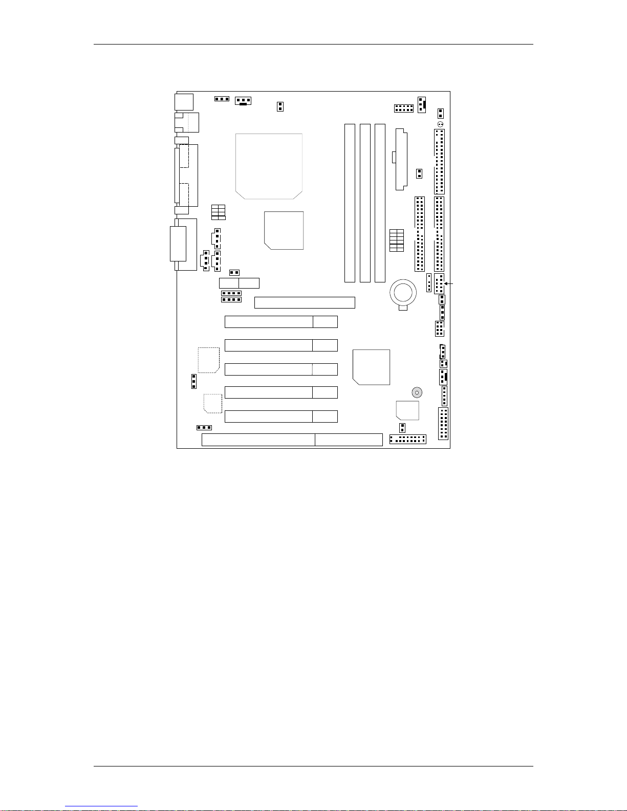
2
6VX7-4X Motherboard Layout
DIMM3
PCI2
PCI3
VT82C686A
GAME & AUDIO
COMB
COMA
LPT
PS/2
SW1
PCI4
PCI5
ISA
DIMM2
DIMM1
SW2
AGP
AMR
JP16
6VX7-4X
PCI1
BAT1
PGA 370
CPU
JP9
JP19
JP30
JP15
JP5
USB
A
TX Power
JP11
Floppy
IDE1
IDE2
J11
JP23
JP1
Front USB
J3
JP2
J4
J12
JP22
J2
BIOS
JP20
Creative
CT5880
JP21
BZ1
JP8
JP7
JP18
J7
J8
J5
VT82C694X
USB2
J1
LAN
3 COM
LED1
Page 6
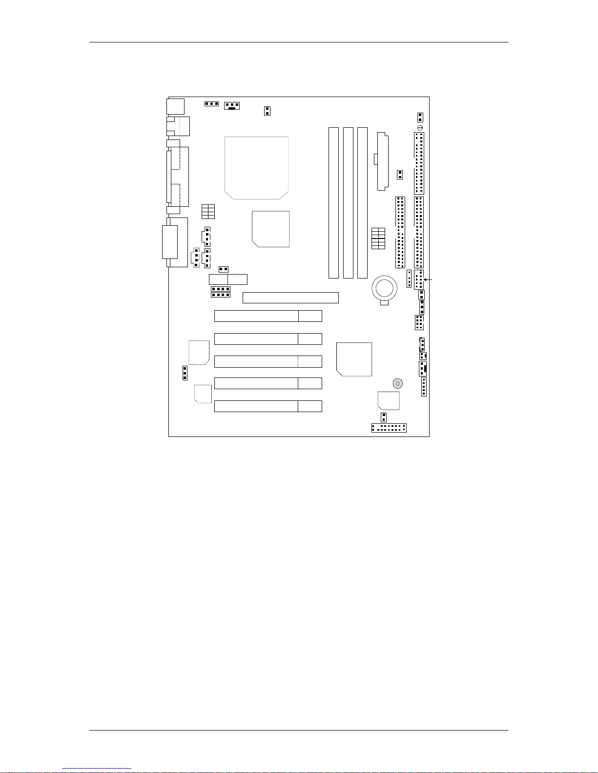
6VX7- 4X / 6VX7B-4X
3
6VX7B-4X Motherboard Layout
DIMM3
PCI2
PCI3
VT82C686B
GAME & AUDIO
COMB
COM
A
LPT
PS/2
SW1
PCI4
PCI5
DIMM2
DIMM1
SW2
AGP
AMR
JP16
6VX7B-4X
PCI1
BAT1
PGA 370
CPU
JP9
JP19
JP5
USB
TX Power
JP11
Floppy
IDE1
IDE2
J11
JP23
JP1
Front USB
J3
JP2
J4
JP22
J2
BIOS
Creative
CT5880
JP21
BZ1
JP8
JP7
JP18
J7
J8
J5
VT82C694X
USB2
J1
LAN
3 COM
LED1
Page 7
6VX7- 4X / 6VX7B-4X
4
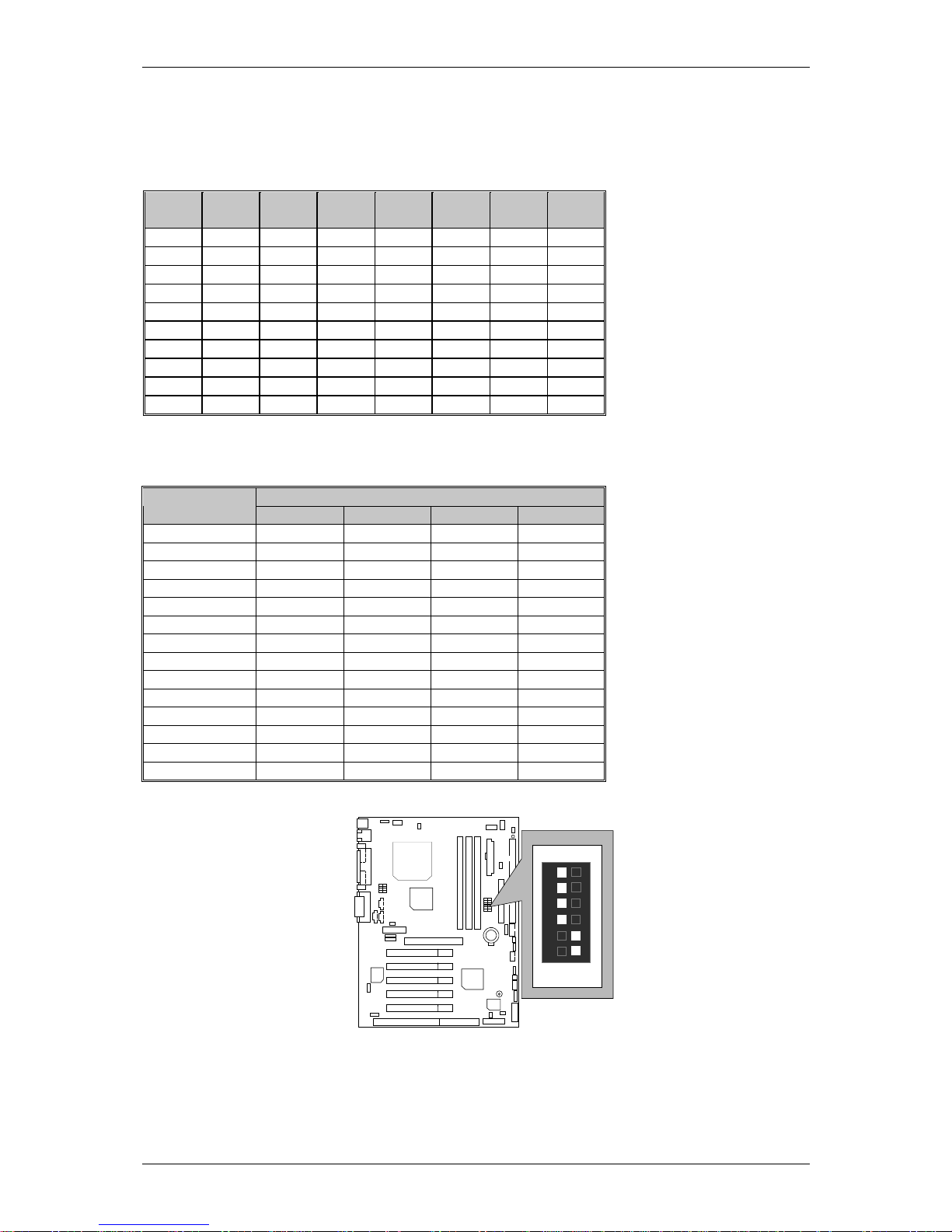
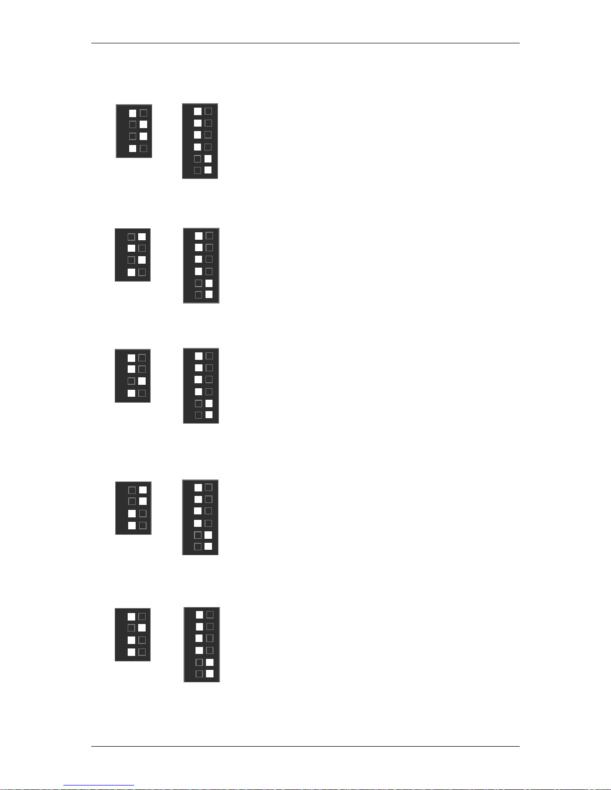
CPU Speed Setup
The system bus speed is selectable at 66,100,133MHz and Auto. The user can select the system bus speed
(SW1) and change the DIP switch (SW2) selection to set up the CPU speed for 300 - 733MHz processor.
SW1:
O : ON, X : OFF
CPU
PCI
CLK
1 2 3 4 5 6
Auto 33.3 X X X X O O
66 33.3 O O X X X X
75 37.5 O O O X X X
83 41.6 O O X O X X
100 33.3 O X X X X X
112 37.3 O X O X X X
124 31 X X X O X X
133 33.3 X X X X X X
140 35 X X O O X X
150 37.5 X X O X X X
The CPU speed must match with the frequency RATIO. It will cause system hanging up if the
frequency RATIO is higher than that of CPU.
SW2:
DIP SWITCH
FREQ. RATIO
1 2 3 4
X 3 OXOO
X 3.5 XXOO
X 4 OOXO
X 4.5 XOXO
X 5 OXXO
X 5.5 XXXO
X 6 OOOX
X 6.5 XOOX
X 7 OXOX
X 7.5 XXOX
X 8 OOXX
X 8.5 XOXX
X 9 OXXX
X 9.5 XXXX
For Auto Jumper setting:
SW1
ON
1
2
3
4
5
6
Note:
1. If you use 66, 100, 133 MHz CPU, we recommend you to set up your system speed to “Auto” value.
2. We don’t recommend you to set up your system speed to 112, 124, 142,152 MHz because these
frequencies are not the standard specifications for CPU, Chipset and most of the peripherals. Whether
your system can run under 112, 124, 142,152 MHz properly will depend on your hardware
configurations: CPU, SDRAM, Cards, etc.
Page 8
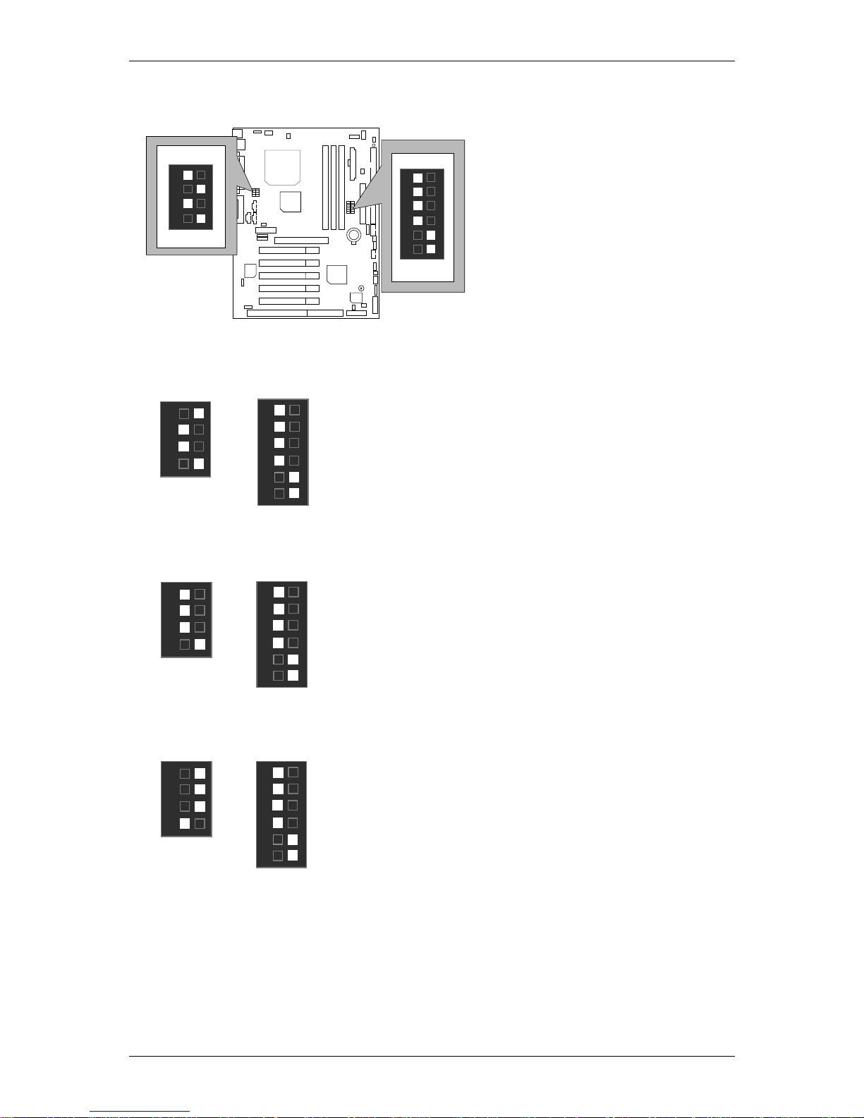
6VX7- 4X / 6VX7B-4X
5
1. CeleronTM 300A / 66MHz FSB
SW2
ON
1
2
3
4
SW1
ON
1
2
3
4
5
6
2. CeleronTM 333 / 6 6MHz FSB
3. Celeron
TM
366 / 66MHz FSB
4. Celeron
TM
400 / 66MHz FSB
SW2
ON
1
2
3
4
SW1
ON
1
2
3
5
4
6
SW2
ON
1
2
3
4
SW2
ON
1
2
3
4
SW1
ON
1
2
3
5
4
6
SW1
ON
1
2
3
5
4
6
Page 9
6VX7- 4X / 6VX7B-4X
6
5. CeleronTM 433 / 66MHz FSB
6. Celeron
TM
466 / 66 MHz FS B
7. Celeron
TM
500 / 66 MHz FS B
8. Celeron
TM
533 / 66 MHz FS B
9. Celeron
TM
566 / 66 MHz FS B
SW2
ON
1
2
3
4
SW2
ON
1
2
3
4
SW2
ON
1
2
3
4
SW2
ON
1
2
4
SW2
ON
1
2
3
4
SW1
ON
1
2
3
5
4
6
SW1
ON
1
2
3
5
4
6
SW1
ON
1
2
3
5
4
6
SW1
ON
1
2
3
5
4
6
SW1
ON
1
2
3
5
4
6
Page 10

6VX7- 4X / 6VX7B-4X
7
10. Cyrix 300 / 100 MHz FSB (Optional)
11. Coppermine 500 / 100MHz FSB
12. Coppermine 550 / 100MHz FSB
13. Coppermine 600 / 100MHz FSB
14. Coppermine 650 / 100MHz FSB
SW2
ON
1
2
3
SW2
ON
1
2
3
4
SW2
ON
1
2
3
4
SW2
ON
1
2
3
4
SW2
ON
1
2
3
4
SW1
ON
1
2
3
5
4
6
SW1
ON
1
2
3
5
4
6
SW1
ON
1
2
3
5
4
6
SW1
ON
1
2
3
5
4
6
SW1
ON
1
2
3
5
4
6
Page 11

6VX7- 4X / 6VX7B-4X
8
15. Coppermine 700 / 100MHz FSB
16. Coppermine 533 / 133MHz FSB
Coppermine 600 / 133MHz FSB
17. Coppermine 667 / 133MHz FSB
18. Coppermine 733 / 133MHz FSB
SW2
ON
1
2
3
4
SW2
ON
1
2
3
4
SW2
ON
1
2
3
4
SW2
ON
1
2
3
4
SW2
ON
1
2
3
4
SW1
ON
1
2
3
5
4
6
SW1
ON
1
2
3
5
4
6
SW1
ON
1
2
3
5
4
6
SW1
ON
1
2
3
5
4
6
SW1
ON
1
2
3
5
4
6
Page 12

6VX7-4X
9
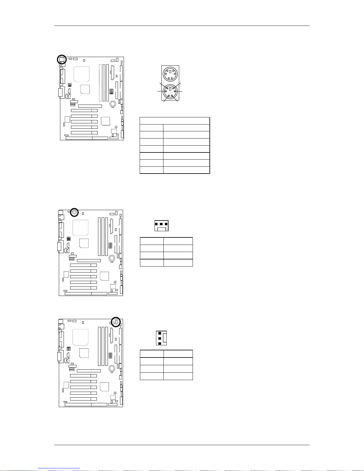
Connectors
Game & Audio Port
MIC In
GAME
Port
Line In
Line Out
COM A / COM B / LPT Port
COM A
LPT PORT
COM B
USB & LAN Connector (LAN is optional)
Pin No. Definition
1 USB V0
2 USB D03 USB D0+
4 GND
5 USB V1
6 USB D17 USB D1+
8 GND
2
1
1 – Green LED
(LAN Link LED)
2 – Yellow LED
(LAN Active LED)
1 2 3 4
5
6
7
8
Page 13
6VX7-4X
10
PS/2 Keyboard & PS/2 Mouse Connector
PS/2 Mouse/ Keyboard
Pin No. Definition
1 Data
2 NC
3 GND
4 VCC(+5V)
5 Clock
6 NC
PS/2 Keyboard
PS/2 Mouse
1
2
3
4
5
6
JP16: CPU Cooling Fan Power Connector
Pin No. Definition
1 GND
2 +12V
3 SENSE
1
JP15: Power Cooling Fan Power Connector (optional)
Pin No. Definition
1 GND
2 +12V
3 NC
1
Page 14
6VX7-4X
11
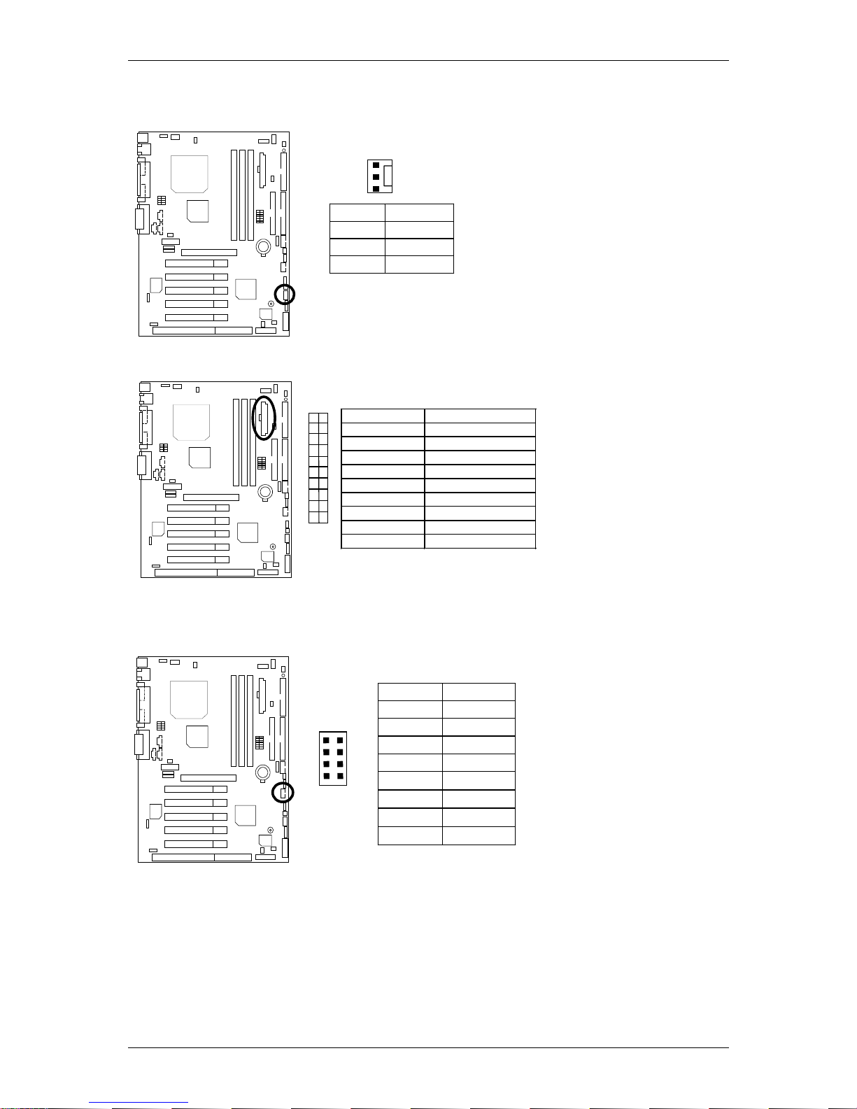
JP2: System Cooling Fan Power Connector
Pin No. Definition
1 GND
2 +12V
3 SENSE
1
ATX Power
Pin No. Definition
3,5,7,13,15-17 GND
1,2,11 3.3V
4,6,19,20 VCC
10 +12V
12 -12V
18 -5V
8 Power Good
9 5V SB stand by+5V
14 PS-ON(Soft On/Off)
10
11
20
1
USB 2 Connector
1
4
Pin No. Definition
1 VCC
2 USB D03 USB D0+
4 GND
5 VCC
6 USB D17 USB D1+
8 GND
5
8
Page 15
6VX7-4X
12
IR Connector
PIN No. Definition
1 VCC(+5V)
2 NC
3 IR data input
4 GND
5 IR data output
1
Floppy Port
RED LINE
IDE1 (Primary), IDE2(S econdary) Port
IDE 1 IDE 2
RED LINE
Page 16

6VX7-4X
13
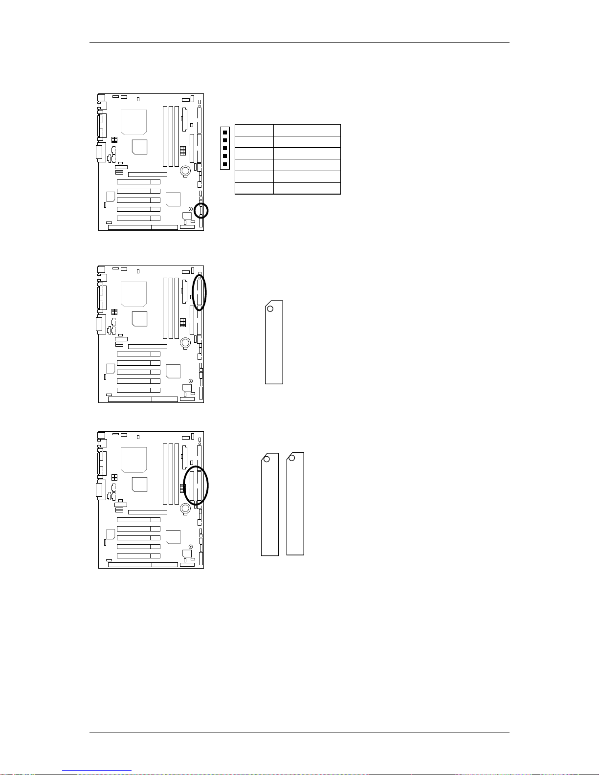
J3: Ring Power On (Internal Modem Card Wake Up)
Pin N o . Definition
1 Signal
2 GND
1
J1: Wake On LAN
Pin No. D efin ition
1 +5V SB
2 GND
3 Signal
1
J7: TEL: The connector is for Modem with internal voice connector
Pin No. Definition
1 Signal-In
2 GND
3 GND
4 Signal-Out
1
Page 17

6VX7-4X
14
J5: AUX_IN
Pin No. Definition
1 AUX-L
2 GND
3 GND
4 AUX-R
1
J8: CD Audio Line In
Pin N o . Definition
1 CD-L
2 GND
3 GND
4 CD-R
1
JP5: STR LED Connector & LED1: DIMM LED
STR LED Connector External
+
DIMM LED
1
Page 18

6VX7-4X
15
Front USB Port (Optional)
Pin No. Definition
1,4,5,10 NC
2 +5V
3,7,9 GND
6 USBP0+
8 USBP0-
2
10
1
9
J11: SM BUS
1
Pin No. D e finition
1 SMB CLK
2 NC
3 GND
4 SMB DATA
5 +5V
Page 19

6VX7-4X
16
Panel And Jumper Definition
J2: For 2X11 Pins Jumper
RE
GN
GD
PW
P+ P
−
P
−
S P K
HD
1
1
1
1
1
GN (Green Switch) Open: Normal Operation
Close: Entering Green Mode
GD (Green LED) Pin 1: LED anode(+)
Pin 2: LED cathode(−)
HD (IDE Hard Disk Active
LED)
Pin 1: LED anode(+)
Pin 2: LED cathode(−)
SPKR (Speaker Connector) Pin 1: VCC(+)
Pin 2- Pin 3: NC
Pin 4: Data(−)
RE (Reset Switch) Open: Normal Operation
Close: Reset Hardware System
P+P−P−(Power LED)
Pin 1: LED anode(+)
Pin 2: LED cathode(−)
Pin 3: LED cathode(−)
PW (Soft Power Connector) Open: Normal Operation
Close: Power On/Off
JP1: Clear CMOS Function
1
Pin N o . Defin ition
1-2 close Normal (Default)
2-3 close Clear CMOS
Page 20

6VX7-4X
17
JP7/JP8/JP18: Onboard AC97 & AMR (Primary or Secondary) Select
(AMR Audio Modem Riser)
Jumper
Function
JP7 JP8 JP18
AC97
(Default)
1-2
Close
1-2
Close
Open
Only AMR
(Primary)
3-4
Close
3-4
Close
Open
AC97+MR
(Secondary)
1-2
Close
1-2 Close
3-4 Close
Close
1
JP8
JP7
JP18
JP11: STR Enable
Pin No. Definition
Open STR Disabled (Default)
Close STR Enabled
1
JP20: Onboard Sound Function Selection (Optional)
Pin No. Definition
1-2 close
Enabled Onboard Sound
(Default)
2-3 close Disable Onboard Sound
1
Page 21

6VX7-4X
18
JP21: Onboard LAN Function (Optional)
Pin No. Definition
1-2 close Onboard LAN Enabled
(Default)
2-3 close Onboard LAN Disabled
1
JP19: Cyrix CPU Turbo Function (Optional)
1
Pin No. Definition
Open Normal
Close Turbo
JP9: USB Device Wake up Selection (Optional)
Pin No. Definition
1-2 close Normal (Default)
2-3 close
Enabled USB Device
Wake up
1
(If you want to use “
USB KB Wakeup from S3~S5
”
function, you have to set the BIOS setting “USB KB Wakeup
from S3~S5” enabled, and the jumper “
JP9
” enabled).
*(Power on the computer and as soon as memory counting
starts, press <Del>. You will enter BIOS Setup. Select the
item “
POWER MANAGEMENT SETUP
”, then select “
USB
KB Wakeup from S3~S5: Enabled
”. Rememb e r to s av e
the setting by pressing "ESC" and choose the “SAVE & EXIT
SETUP” option.)
Page 22

6VX7-4X
19
JP23: Case Open
Pin No. Definition
1 Signal
2 GND
1
JP22: BIOS Flash ROM Write Protect (Optional)
1
Pin No. Definition
Close BIOS Write Disabled
Open
BIOS Write Enabled
(Default)
Please set Jumper JP22 to “Open”
to enabled BIOS write function when
you update new BIOS or new device.
JP30: Over Voltage CPU Speed Up (Optional)
Pin No. Definition
1-2 close 40%
3-4 close 30%
5-6 close 20%
7-8 close 10%
9-10 close Norm al
1
10
9
2
Page 23

6VX7-4X
20
J12: Front Panel Jumper (Optional)
Pin No. Definition
1 HD LED+
2 GN LED+
3 HD LED-
4 PWR LED+
5,7 RESET SW
6,8 Soft ON/OFF
10,12 Green SW
9 +5V
11 IR RX
13 GND
15 IRTX
14 NC
16 IR Power
1
2
15
16
BAT1: Battery
+
☞
Danger of explosion if batter y
is incorrectly replaced.
☞
Replace only with the same or
equivalent type recommended
by the manufacturer.
☞
Dispose of used batteries
according to the manufacturer’s
instructions.
Page 24

6ZM7/6ZM7A
21
3.3V DIMM
DIMM Sockets
Floppy
Block Diagram
14.318MHz
33 MHz
PCI Bus
A
GP Bus
LPT
PS/2 KB/Mouse
COM Ports
IR
USB Bus
14.318MHz
48MHz
Host Bus
VIA
VT82C694X
VIA
VT82C686A /
VT82C686B
66 /100/133 MHz
66 /100 /133 MHz
33 MHz
ISA Bus
AC97
CODEC
Ultra DMA
33/ATA66
IDE Ports
AMR
Slot
A
C’97-Link
Creative
CT5880
IDE Bus
USB Port
A
GP 2X/4
X
66 /100 /133 MHz
24MHz
ICS 9248DF-39
PGA 370 CPU
3 COM
Page 25

6VX7-4X
22
Memory Installation
The motherboard has 3 dual inline memory module (DIMM) sockets. The BIOS will automatically detects memory
type and size. To install the memory module, just push it vertically into the DIMM Slot .The DIMM module can
only fit in one direction due to the two notch. Memory size can vary between sockets.
Install memory in any combination table:
DIMM 168-pin SDRAM DIMM Modules
DIMM1 Supports 16 / 32 / 64 / 128 / 256 / 512MB X 1 pcs
DIMM2 Supports 16 / 32 / 64 / 128 / 256 / 512MB X 1 pcs
DIMM3 Supports 16 / 32 / 64 / 128 / 256 / 512MB X 1 pcs
Page 26

6VX7-4X
23
BIOS Setup
BIOS Setup is an overview of the BIOS Setup Program. The program that allows users to modify the basic
system configuration. This type of information is stored in battery-backed CMOS RAM so that it retains the Setup
information when the power is turned off.
ENTERING SETUP
Power ON the computer and press <Del> immediately will allow you to enter Setup. If the message disappears
before you respond and you still wish to enter Setup, restart the system to try again by turning it OFF then ON or
pressing the "RESET" bottom on the system case. You may also restart by simultaneously press <Ctrl> − <Alt>−
<Del> keys.
CONTROL KEYS
<↑> Move to previous item
<↓> Move to next item
<←> Move to the item in the left hand
<→> Move to the item in the right hand
<Esc> Main Menu - Quit and not save changes into CMOS
Status Page Setup Menu and Option Page Setup Menu Exit current page and return to Main Menu
<+/PgUp> Increase the numeric value or make changes
<-/PgDn> Decrease the numeric value or make changes
<F1> General help, only for Status Page Setup Menu and Option
Page Setup Menu
<F2> Reserved
<F3> Reserved
<F4> Reserved
<F5> Restore the previous CMOS value from CMOS, only for
Option Page Setup Menu
<F6> Load the default CMOS value from BIOS default table, only
for Option Page Setup Menu
<F7>
Load the Setup Defaults.
<F8> Reserved
<F9> Reserved
<F10> Save all the CMOS changes, only for Main Menu
Page 27

6VX7-4X
24
GETTING HELP
Main Menu
The on-line description of the highlighted setup function is displayed at the bottom of the screen.
Status Page Setup Menu / Option Page Setup Menu
Press F1 to pop up a small help window that describes the appropriate keys to use and the possible selections
for the highlighted item. To exit the Help Window press <Esc>.
The Main Menu
Once you enter AMI BIOS CMOS Setup Utility, the Main Menu (Figure 1) will appear on the screen. The Main
Menu allows you to select from nine setup functions and two exit choices. Use arrow keys to select among the
items and press <Enter> to accept or enter the sub-menu.
Figure 1: Main Menu
•••• Standard CMOS Setup
This setup page includes all the items in standard compatible BIOS.
•••• BIOS Features Setup
This setup page includes all the items of AMI special enhanced features.
•••• Chipset Features Setup
This setup page includes all the items of chipset special features.
•••• Power Management Setup
This setup page includes all the items of Green function features.
•••• PnP/PCI Configurations
This setup page includes all the configurations of PCI & PnP ISA resources.
•••• Load BIOS Defaults
Bios Defaults indicates the value of the system parameter which the system would be in the safe
configuration.
•••• Load Setup Defaults
Setup Defaults indicates the value of the system parameter which the system would be in the most
appropriate configuration.
•••• Integrated Peripherals
This setup page includes all onboard peripherals.
•••• Hardware Monitor Setup
This setup page is auto detect fan and temperature status.
AMIBIOS SIMPLE SETUP UTILITY-VERSION 1.20
( C ) 1998 American Megatrends, Inc. All Rights Reserved
STANDARD CMOS SETUP INTEGRATED PERIPHERALS
BIOS FEATURES SETUP HARDWARE MONITOR SETUP
CHIPSET FEATURES SETUP SUPERVISOR PASSWORD
POWER MANAGEMENT SETUP USER PASSWORD
PNP/PCI CONFIGURATION IDE HDD AUTO DETECTION
LOAD BIOS DEFAULTS SAVE & EXIT SETUP
LOAD SETUP DEFAULTS EXIT WITHOUT SAVING
ESC : Quit ↑↓←→ : Select Item (Shift) F2 : Change Color F5 : Old Values
F6 : Load BIOS Defaults F7: Load Setup Defaults F10: Save & Exit
Time, Date, Hard Disk Type, …
Page 28

6VX7-4X
25
•••• Supervisor password
Change, set, or disable password. It allows you to limit access to the system and Setup, or just to Setup.
•••• User password
Change, set, or disable password. It allows you to limit access to the system.
•••• IDE HDD auto detection
Automatically configure hard disk parameters.
•••• Save & Exit Setup
Save CMOS value settings to CMOS and exit setup.
•••• Exit Without Saving
Abandon all CMOS value changes and exit setup.
Page 29

6VX7-4X
26
Standard CMOS Setup
The items in Standard CMOS Features Menu (Figure 2) are divided into 9 categories. Each category includes no,
one or more than one setup items. Use the arrows to highlight the item and then use the <PgUp> or <PgDn>
keys to select the value you want in each item.
Figure 2: Standard CMOS Setup
•••• Date
The date format is <Week>, <Month>, <Day>, <Year>.
Week The week, from Sun to Sat, determined by the BIOS and is
display-only
Month The month, Jan. Through Dec.
Day The day, from 1 to 31 (or the maximum allowed in the
month)
Year The year, from 1980 through 2099
•••• Time
The times format in <hour> <minute> <second>. The time is calculated base on the 24-hour military-time
clock. For example, 1 p.m. is 13:00:00.
•••• IDE Primary Master, Slave / Secondary Master, Slave
The category identifies the types of hard disk from drive C to F that has been installed in the computer.
There are two types: auto type, and user definable type. User type is user-definable; Auto type which will
automatically detect HDD type.
Note that the specifications of your drive must match with the drive table. The hard disk will not work properly
if you enter improper information for this category.
If you select User Type, related information will be asked to enter to the following items. Enter the
information directly from the keyboard and press <Enter>. Such information should be provided in the
documentation form your hard disk vendor or the system manufacturer.
CYLS. Number of cylinders
HEADS number of heads
PRECOMP write precomp
LANDZONE Landing zone
SECTORS number of sectors
If a hard disk has not been installed select NONE and press <Enter>.
AMIBIOS SETUP – STANDARD CMOS SETUP
( C ) 1998 American Megatrends, Inc. All Rights Reserved
Date (mm/dd/yyyy) : Web Oct 27, 1999
Time (hh/mm/ss) : 10:36:24
TYPE SIZE CYLS HEAD PRECOMP LANDZ SECTOR MODE
Pri Master : Auto
Pri Slave : Auto
Sec Master : Auto
Sec Slave : Auto
Floppy Drive A: 1.44 MB 3 ½
Floppy Driver B: Not Installed
Boot Sector Virus Protection : Disabled
Base Memory : 640 Kb
Other Memory: 384 Kb
Extended Memory: 30Mb
Total Memory: 31Mb
Month: Jan – Dec ESC : Exit
Day: 01 – 31 ↑↓ : Select Item
Year : 1980– 2099 PU/PD/+/– : Modify
(Shift)F2 : Color
Page 30

6VX7-4X
27
•••• Drive A type / Drive B type
The category identifies the types of floppy disk drive A or drive B that has been installed in the computer.
None No floppy drive installed
360K, 5.25 in. 5.25 inch PC-type standard drive; 360K byte capacity.
1.2M, 5.25 in. 5.25 inch AT-type high-density drive; 1.2M byte
capacity (3.5 inch when 3 Mode is Enabled).
720K, 3.5 in. 3.5 inch double-sided drive; 720K byte capacity
1.44M, 3.5 in. 3.5 inch double-sided drive; 1.44M byte capacity.
2.88M, 3.5 in. 3.5 inch double-sided drive; 2.88M byte capacity.
•••• Boot Sector Virus Protection
If it is set to enable, the category will flash on the screen when there is any attempt to write to the boot sector
or partition table of the hard disk drive. The system will halt and the following error message will appear in
the mean time. You can run anti-virus program to locate the problem.
Enabled Activate automatically when the system boots up causing a
warning message to appear when anything attempts to
access the boot sector or hard disk partition table
Disabled No warning message to appear when anything attempts to
access the boot sector or hard disk partition table. (Default
Value)
•••• Memory
The category is display-only which is determined by POST (Power On Self Test) of the BIOS.
Base Memory
The POST of the BIOS will determine the amount of base (or conventional) memory installed in the
system.
The value of the base memory is typically 512 K for systems with 512 K memory installed on the
motherboard, or 640 K for systems with 640 K or more memory installed on the motherboard.
Extended Memory
The BIOS determines how much extended memory is present during the POST.
This is the amount of memory located above 1 MB in the CPU's memory address map.
Other Memory
This refers to the memory located in the 640 K to 1024 K address space. This is memory that can
be used for different applications.
DOS uses this area to load device drivers to keep as much base memory free for application
programs. Most use for this area is Shadow RAM
Page 31

6VX7-4X
28
BIOS Features Setup
Figure 3: BIOS Features Setup
•••• Quick Boot
Enabled Enabled Quick Boot Function. (Default Value)
Disabled Disabled Quick Boot Function.
•••• 1st / 2nd / 3rd Boot Device
The default value is Floppy or LS-120 / ZIP A: or ATAPI ZIP C: or CDROM or SCSI or NET W ORK / I20 or
IDE-0~IDE-3 or Disabled.
Floppy Boot Device by Floppy.
LS-120 / ZIP A: Boot Device by LS-120 / ZIP A:.
CDROM Boot Device by CDROM.
SCSI Boot Device by SCSI.
NETWORK Boot Devic e by NETWORK.
IDE-0~IDE-3 Boot Device by IDE-0~IDE-3.
Disabled Boot Device by Disabled.
ATAPI ZIP C: Boot Device by ATAPI ZIP C:.
•••• Try Other Boot Device
Yes Enabled other device to boot system. (Default Value)
No Disabled other device to boot system.
•••• Floppy Access Control
Read-Write Set Floppy Access Control : Read-Write. (Default
Value)
Read-Only Set Floppy Access Control : Read Only.
•••• Hard Disk Access Control
Read-Write Set Hard Disk Access Control : Read-Write. (Default
Value)
Read-Only Set Hard Disk Access Control : Read Only.
•••• S.M.A.R.T. for Hard Disks
Enable Enable S.M.A.R.T. Hard for Disks.
Disable Disable S.M.A.R.T. Hard for Disks. (Default Value)
AMIBIOS SETUP – BIOS FEATURES CMOS SETUP
( C ) 1998 American Megatrends, Inc. All Rights Reserved
Quick Boot :Enabled D000, 16K Shadow :Disabled
1st Boot Device :Floppy D400, 16K Shadow :Disabled
2nd Boot Device :IDE-0 D800, 16K Shadow :Disabled
3rd Boot Device :CDROM DC00, 16K Shadow :Disabled
Try Other Boot Device :Yes
Floppy Access Control :Read-Write
Hard Disk Access Control :Read-Write
S.M.A.R.T for Hard Disks :Disabled
BootUp Num-Lock :On
Floppy Drive Swap :Disabled
Floppy Drive Seek :Disabled
Password Check :Setup
Boot To OS/2 > 64MB :No
CPU Serial Number :Disabled
L1/L2 Cache :WriteBack
Cache Bus ECC :Disabled ESC : Quit
↑↓←→: Select Item
System BIOS Cacheable :Enabled F1 : Help PU/PD/+/- : Modify
C000, 32K Shadow :Cached F5 : Old Values (Shift)F2 :Color
C800, 16K Shadow :Disabled F6 : Load BIOS Defaults
CC00, 16K Shadow :Disabled F7 : Load Setup Defaults
Page 32

6VX7-4X
29
•••• Boot Up Num-Lock
On Keypad is number keys. (Default Value)
Off Keypad is arrow keys.
•••• Floppy Drive Swap
Enabled Floppy A & B will be swapped under DOS.
Disabled Floppy A & B will be normal definition. (Default Value)
•••• Floppy Drive Seek
During POST, BIOS will determine if the floppy disk drive installed is 40 or 80 tracks. 360 type is 40 tracks
while 720 , 1.2 and 1.44 are all 80 tracks.
Enabled BIOS searches for floppy disk drive to determine if it is 40
or 80 tracks. Note that BIOS can not tell from 720, 1.2 or
1.44 drive type as they are all 80 tracks.
Disabled BIOS will not search for the type of floppy disk drive by
track number. Note that there will not be any warning
message if the drive installed is 360. (Default Value)
•••• Password Check
Setup Set Password Check to Setup. (Default Value)
Always Set Password Check to Always.
•••• Boot To OS/2 > 64MB
Yes Enabled Boot To OS/2.
No Disabled Boot To OS/2. (Default Value)
•••• CPU Serial Number
Disabled Disabled CPU Serial Number. (Default Value)
Enabled Enabled CPU Serial Number.
•••• L1 /L2 Cache
WriteBack Set L1 Cache is WriteBack. (Default Value)
Disabled Disabled this Function.
•••• Cache Bus ECC
Enabled Enable Cache Bus ECC.
Disabled Disable Cache Bus ECC. (Default Value)
•••• System BIOS Cacheable
Enabled Enabled System BIOS Cacheable. (Default Value)
Disabled Disabled System BIOS Cacheable.
•••• C000 32K Shadow- DC00 16K Shadow
These categories determine whether optional ROM will be copied to RAM by 16 byte.
Enabled Optional shadow is enabled.
Disabled Optional shadow is disabled.
Cached Optional shadow is cached.
Page 33

6VX7-4X
30
Chipset Features Setup
Figure 4: Chipset Features Setup
•••• SDRAM Timing by SPD
Disabled SDRAM Timing by SPD Function Disabled. (Default
Value)
Enabled SDRAM Timing by SPD Function Enabled.
•••• DRAM Frequency
100MHz Set DRAM Frequency is 100MHz. (Default Value)
66MHz Set DRAM Frequency is 66MHz.
133MHz Set DRAM Frequency is 133MHz.
•••• Bank 0/1 DRAM Timing
Fast Set Bank 0/1 DRAM Timing to Fast.
Normal Set Bank 0/1 DRAM Timing to Normal. (Default Value)
Turbo Set Bank 0/1 DRAM Timing to Turbo.
•••• Bank 2/3 DRAM Timing
Fast Set Bank 2/3 DRAM Timing to Fast.
Normal Set Bank 2/3 DRAM Timing to Normal. (Default Value)
Turbo Set Bank 2/3 DRAM Timing to Turbo.
•••• Bank 4/5 DRAM Timing
Fast Set Bank 4/5 DRAM Timing to Fast.
Normal Set Bank 4/5 DRAM Timing to Normal. (Default Value)
Turbo Set Bank 4/5 DRAM Timing to Turbo.
•••• SDRAM CAS# Latency
3 For Slower SDRAM DIMM module. (Default Value)
2 For Fastest SDRAM DIMM module.
•••• C2P Concurrency & Master
Enabled Enabled C2P Concurrency & Master. (Default Value)
Disabled Disabled C2P Concurrency & Master.
•••• DRAM Integrity Mode
ECC For 72 bit ECC type DIMM Modle.
Disabled Normal Setting. (Default Value)
AMIBIOS SETUP –CHIPSET FEATURE CMOS SETUP
( C ) 1998 American Megatrends, Inc. All Rights Reserved
*** DRAM Timing *** PCI Dynamic Bursting :Enabled
SDRAM Timing by SPD :Disabled PCI Master 0 W/S Write :Enabled
DRAM Frequency :100Mhz PCI Delay Transaction :Disabled
Bank 0/1 DRAM Timing :Normal AGP Master 1 W/S Write :Disabled
Bank 2/3 DRAM Timing :Normal AGP Master 1 W/S Read :Disabled
Bank 4/5 DRAM Timing :Normal ISA Bus Clock :PCICLK/4
SDRAM CAS# Latency :3 VGA Frame Buffer USWC :Disabled
PCI Frame Buffer USWC :Disabled
C2P Concurrency & Master :Enabled ClkGen Spread Spectrum :Enabled
DRAM Integrity Mode :Disabled ClkGen for DIMM Slot :Enabled
Memory Hole :Disabled USB Controller :USB Port 0&1
AGP Mode :4X USB Legacy Support :Disabled
AGP Comp. Driving :Auto
Manual AGP Comp. Driving :CB
AGP Aperture Size :64MB
Peer Concurrency :Disabled
ESC : Quit ↑↓←→: Select Item
Delay Transaction :Disabled F1 : Help PU/PD/+/- : Modify
PCI Master Access PMRDY :Enabled F5 : Old Values (Shift)F2 :Color
PCI Read Caching :Disabled F6 : Load BIOS Defaults
CPU TO PCI Write Buffer :Disabled F7 : Load Setup Defaults
Page 34

6VX7-4X
31
•••• Memory Hole
512KB640KB
Set Address=512KB-640KB relocate to ISA BUS.
14M-16M Set Address=14-16MB relocate to ISA BUS.
15M-16M Set Address=15-16MB relocate to ISA BUS.
Disabled Normal Setting. (Default Value)
•••• AGP Mode
4X Set AGP Mode is 4X. (Default Value)
1X Set AGP Mode is 1X.
2X Set AGP Mode is 2X.
•••• AGP Comp. Driving
Auto Set AGP Comp. Driving is Auto. (Default Value)
Manual Set AGP Comp. Driving is Manual.
If AGP Comp. Driving is Manual.
Manual AGP Comp. Driving : 00~FF
•••• AGP Aperture Size
4MB Set AGP Aperture Size to 4MB.
8MB Set AGP Aperture Size to 8 MB.
16MB Set AGP Aperture Size to 16 MB.
32MB Set AGP Aperture Size to 32 MB.
64MB Set AGP Aperture Size to 64 MB. (Default Value)
128MB Set AGP Aperture Size to 128 MB.
256MB Set AGP Aperture Size to 256 MB.
•••• Peer Concurrency
Enabled Enabled Peer Concurrency function.
Disabled Disabled Peer Concurrency function. (Default Value)
•••• Delay Transaction
Disabled Normal operation. (Default Value)
Enabled For slow speed ISA device in system.
•••• PCI Master Access PMRDY
Enabled Enabled PCI Master Access PMROY function. (Default
Value)
Disabled Disabled PCI Master Access PMROY function
•••• PCI Read Caching
Enabled Enabled PCI Read Caching function.
Disabled Disabled PCI Read Caching function. (Default Value)
•••• CPU TO PCI Write Buffer
Enabled Enabled CPU to PCI Write Buffer.
Disabled Disabled CPU to PCI Write Buffer. (Default Value)
•••• PCI Dynamic Bursting
Enabled Enabled Dynamic Bursting function. (Default Value)
Disabled Disabled Dynamic Bursting function.
•••• PCI Master 0 W/S Write
Enabled Enabled PCI Master 0 W/s Write. (Default Value)
Disabled Disabled PCI Master 0 W/s Write.
Page 35

6VX7-4X
32
•••• PCI Delay Transaction
Enabled Enabled Delay Transaction.
Disabled Disabled Delay Transaction. (Default Value)
•••• AGP Master 1 W/S Write
Enabled Enabled AGP Master 1 W/S Write.
Disabled Disabled AGP Master 1 W/S Write. (Default Value)
•••• AGP Master 1 W/S Read
Enabled Enabled AGP Master 1 W/S Read.
Disabled Disabled AGP Master 1 W/S Read. (Default Value)
•••• ISA Bus Clock
PCICLK/4
Set ISA Bus Clock is PCICLK/4. (Default Value)
PCICLK/2 Set ISA Bus Clock is PCICLK/2.
PCICLK/3 Set ISA Bus Clock is PCICLK/3.
PCICLK/5 Set ISA Bus Clock is PCICLK/5.
PCICLK/6 Set ISA Bus Clock is PCICLK/6.
•••• VGA Frame Buffer USWC
Enabled Enabled VGA Frame Buffer USWC.
Disabled Disabled VGA Frame Buffer USWC. (Default Value)
•••• PCI Frame Buffer USWC
Enabled Enabled PCI Frame Buffer USWC.
Disabled Disabled PCI Frame Buffer USWC. (Default Value)
•••• ClkGen Spread Spectrum
Disabled Disabled ClkGen Spread Spectrum.
Enabled Enabled ClkGen Spread Spectrum. (Default Value)
•••• ClkGen for DIMM Slot
Enabled ClkGen for DIMM Slot Enabled. (Default Value)
Disabled ClkGen for DIMM Slot Disabled.
•••• USB Controller
USB Port 0&1 USB Controller for USB Port 0&1. (Default
Value)
USB Port 2&3 USB Controller for USB Port 2&3.
All USB Port USB Controller for All USB Port.
Disabled USB Controller Function Disabled.
•••• USB Legacy Support
Keyboard Set USB Legacy Support Keyboard.
Keyb+Mouse Set USB Legacy Support Keyboard +Mouse.
Disabled
Disabled USB Legacy Support Function. (Default
Value)
Page 36

6VX7-4X
33
Power Management Setup
Figure 5: Power Management Setup
•••• ACPI Sleep type
S1/POS Set ACPI Sleep type is S1 (Default Value)
S3/STR Set ACPI Sleep type is S3.
•••• USB KB Wakeup From S3~S5
Enabled Enable USB Keyboard Wakeup from system.
Disabled Disable USB Keyboard Wakeup from system. (Default
Value)
•••• Power Management / APM
Enabled Enable Green & software APM function. (Default Value)
Disabled Disable Green & software APM function.
•••• Video Power Down Mode
Disabled Disabled Video Power Down Mode Function.
Suspend Set Video Power Down Mode to Suspend. (Default Value)
Stand By Set Video Power Down Mode to Stand By.
•••• Hard Disk Power Down Mode
Disabled Disabled Hard Disk Power Down Mode Function.
Suspend Set Hard Disk Power Down Mode to Suspend (Default
Value)
Stand By Set Hard Disk Power Down Mode to Stand By.
•••• Standby Time Out (Minute.)
Disabled Disabled Standby Time Out Function. (Default Value)
1 Enabled Standby Time Out after 1min.
2 Enabled Standby Time Out after 2min.
4 Enabled Standby Time Out after 4min.
8 Enabled Standby Time Out after 8min.
10 Enabled Standby Time Out after 10min.
20 Enabled Standby Time Out after 20min.
30 Enabled Standby Time Out after 30min.
40 Enabled Standby Time Out after 40min.
50 Enabled Standby Time Out after 50min.
60 Enabled Standby Time Out after 60min.
AMIBIOS SETUP –POWER MANAGEMENT SETUP
( C ) 1998 American Megatrends, Inc. All Rights Reserved
ACPI Sleep type :S1/POS Modem Use IRQ :4
USB KB Wakeup From S3~S5 :Disabled Modem Ring On/Wake On Lan :Enabled
Power Management/APM :Enabled PME Event Wake up :Disabled
Video Power Down Mode :Suspend RTC Alarm Power On :Disabled
Hard Disk Power Down Mode :Suspend RTC Alarm Date :15
Standby Time Out (Minute) :Disabled RTC Alarm Hour :12
Suspend Time Out(Minute) :Disabled RTC Alarm Minute :30
Display Activity :Ignore RTC Alarm Second :30
IRQ3 :Monitor
IRQ 4 :Monitor
IRQ 5 :Ignore
IRQ 7 :Monitor
IRQ 9 :Ignore
IRQ 10 :Ignore
IRQ 11 :Ignore
IRQ 13 :Ignore
IRQ 14 :Monitor
ESC : Quit ↑↓←→: Select Item
IRQ 15 :Ignore F1 : Help PU/PD/+/- : Modify
System Thermal :Ignore F5 : Old Values (Shift)F2 :Color
Soft-off by Power Button :Instant off F6 : Load BIOS Defaults
AC Back Function :Last Stats F7 : Load Setup Defaults
Page 37

6VX7-4X
34
•••• Suspend Time Out (Minute.)
Disabled Disabled Suspend Time Out Function. (Default Value)
1 Enabled Suspend Time Out after 1min.
2 Enabled Suspend Time Out after 2min.
4 Enabled Suspend Time Out after 4min.
8 Enabled Suspend Time Out after 8min.
10 Enabled Suspend Time Out after 10min.
20 Enabled Suspend Time Out after 20min.
30 Enabled Suspend Time Out after 30min.
40 Enabled Suspend Time Out after 40min.
50 Enabled Suspend Time Out after 50min.
60 Enabled Suspend Time Out after 60min.
•••• Display Activity
Ignore Ignore Display Activity. (Default Value)
Monitor Monitor Display Activity.
•••• IRQ 3~IRQ15
Ignore Ignore IRQ3 ~IRQ15.
Monitor Monitor IRQ3~IRQ15.
•••• System Thermal
Ignore Ignore System Thermal. (Default Value)
Monitor Monitor System Thermal.
•••• Soft-off by Power Button
Instant off Soft switch ON/OFF for Power Button. (Default Value)
Delay4Sec
Soft switch ON 4 Sec for Power off.
•••• AC Back Function
Power Off Set Restore on AC/Power Loss is Power off.
Power On Set Restore on AC/Power Loss is Power on.
Last stats Set Restore on AC/Power Loss is Last state mode.
(Default Value)
•••• MODEM Use IRQ
NA Set MODEM Use IRQ to NA.
3 Set MODEM Use IRQ to 3.
4 Set MODEM Use IRQ to 4. (Default Value)
5 Set MODEM Use IRQ to 5.
7 Set MODEM Use IRQ to 7.
•••• Modem Ring on/Wake on LAN
Disabled Disabled Modem Ring on/Wake on LAN.
Enabled Enabled Modem Ring on/Wake on LAN. (Default
Value)
•••• PME Event Wake up
Disabled Disabled PME Event Wake up function. (Default
Value)
Enabled Enabled PME Event Wake up function.
Page 38

6VX7-4X
35
•••• RTC Alarm Power On
You can set “RTC Alarm Power On” item to Enabled and key in date/time to power on
system.
Disabled Disable this function. (Default Value)
Enabled Enable alarm function to POWER ON system.
If the “RTC Alarm Power On” is Enabled.
RTC Alarm Date : Every Day,1~31
RTC Alarm Hour: 0~23
RTC Alarm Minute : 0~59
RTC Alarm Second : 0~59
Page 39

6VX7-4X
36
PnP/PCI Configurations
Figure 6: PnP/PCI Configuration
•••• Plug and Play Aware O/S
Yes Enable Plug and Play Aware O/S function.
No
Disable Plug and Play Aware O/S function (Default Value)
•••• Clear NVRAM
Yes Set Clear NVRAM.
No
Set don’t clear NVRAM. (Default Value)
•••• Primary Graphics Adapter
AGP Primary Graphics Adapter From Add-on AGP. (Default
Value)
PCI Primary Graphics Adapter From OnBoard PCI.
•••• PCI VGA Palette Snoop
Enabled For h a v i n g V i deo Card on ISA Bus and VGA C ard on PCI Bus.
Disabled For VGA Card only. (Default Value)
•••• DMA Channel (0,1,3,5,6,7)
PnP The resource is used by PnP device.
ISA / EISA The resource is used by ISA / EISA device (PCI or ISA).
•••• IRQ (3,4,5,7, 9,10,11,14,15)
PCI/PnP The resource is used by PCI/PnP device.
ISA / EISA The resource is used by ISA / EISA device (PCI or ISA).
AMIBIOS SETUP –PNP/PCI CONFIGURATION SETUP
( C ) 1998 American Megatrends, Inc. All Rights Reserved
Plug and Play Aware O/S :No
Clear NVRAM :No
Primary Graphics Adapter :AGP
PCI VGA Palette Snoop :Disabled
DMA Channel 0 :PnP
DMA Channel 1 :PnP
DMA Channel 3 :PnP
DMA Channel 5 :PnP
DMA Channel 6 :PnP
DMA Channel 7 :PnP
IRQ 3 :PCI/PnP
IRQ 4 :PCI/PnP
IRQ 5 :PCI/PnP
IRQ 7 :PCI/PnP
IRQ 9 :PCI/PnP ESC : Quit ↑↓←→: Select Item
IRQ 10 :PCI/PnP F1 : Help PU/PD/+/- : Modify
IRQ 11 :PCI/PnP F5 : Old Values (Shift)F2 :Color
IRQ 14 :PCI/PnP F6 : Load BIOS Defaults
IRQ 15 :PCI/PnP F7 : Load Setup Defaults
Page 40

6VX7-4X
37
Load BIOS Defaults
Figure 7: Load BIOS Defaults
•••• Load BIOS Defaults
BIOS defaults contain the most appropriate values of the system parameters that allow minimum system
performance.
AMIBIOS SIMPLE SETUP UTILITY-VERSION 1.20
( C ) 1998 American Megatrends, Inc. All Rights Reserved
STANDARD CMOS SETUP INTEGRATED PERIPHERALS
BIOS FEATURES SETUP HARDWARE MONITOR SETUP
CHIPSET FEATURES SETUP SUPERVISOR PASSWORD
POWER MANAGEMENT SETUP USER PASSWORD
PNP/PCI CONFIGURATION IDE HDD AUTO DETECTION
LOAD BIOS DEFAULTS SAVE & EXIT SETUP
LOAD SETUP DEFAULTS EXIT WITHOUT SAVING
ESC : Quit ↑↓→← : Select Item (Shift) F2 : Change Color F5 : Old Values
F6 : Load BIOS Defaults F7: Load Setup Defaults F10: Save & Exit
Load BIOS Default except Standard CMOS Setup
Load BIOS Defaults (Y/ N)? N
Page 41

6VX7-4X
38
Load Setup Defaults
Figure 8: Load Setup Defaults
•••• Load Setup Defaults
Selecting this field loads the factory defaults for BIOS and Chipset Features which the system automatically
detects.
AMIBIOS SIMPLE SETUP UTILITY-VERSION 1.20
( C ) 1998 American Megatrends, Inc. All Rights Reserved
STANDARD CMOS SETUP INTEGRATED PERIPHERALS
BIOS FEATURES SETUP HARDWARE MONITOR SETUP
CHIPSET FEATURES SETUP SUPERVISOR PASSWORD
POWER MANAGEMENT SETUP USER PASSWORD
PNP/PCI CONFIGURATION IDE HDD AUTO DETECTION
LOAD BIOS DEFAULTS SAVE & EXIT SETUP
LOAD SETUP DEFAULTS EXIT WITHOUT SAVING
ESC : Quit ↑↓→← : Select Item (Shift) F2 : Change Color F5 : Old Values
F6 : Load BIOS Defaults F7: Load Setup Defaults F10: Save & Exit
Load Setup Default except Standard CMOS Setup
Load SETUP Defaults (Y/N)? N
Page 42

6VX7-4X
39
Integrated Peripherals
Figure 9: Integrated Peripherals
•••• OnBoard IDE
Disabled Disabled OnBoard IDE
Both Set OnBoard IDE is Both. (Default Value)
Primary Set OnBoard IDE is Primary.
Secondary Set OnBoard IDE is Secondary.
•••• OnBoard FDC
Auto Set OnBoard FDC is Auto. (Default Value)
Disabled Disabled OnBoard FDC.
Enabled Enabled OnBoard FDC.
•••• OnBoard Serial Port 1
Auto BIOS will automatically setup the port 1 address.
(Default Value)
3F8/COM1 Enable onBoard Serial port 1 and address is 3F8.
2F8/COM2 Enable onBoard Serial port 1 and address is 2F8.
3E8/COM3 Enable onBoard Serial port 1 and address is 3E8.
2E8/COM4 Enable onBoard Serial port 1 and address is 2E8.
Disabled Disable onBoard Serial port 1.
•••• OnBoard Serial Port 2
Auto BIOS will automatically setup the port 2 address.
(Default Value)
3F8/COM1 Enable onBoard Serial port 2 and address is 3F8.
2F8/COM2 Enable onBoard Serial port 2 and address is 2F8.
3E8/COM3 Enable onBoard Serial port 2 and address is 3E8.
2E8/COM4 Enable onBoard Serial port 2 and address is 2E8.
Disabled Disable onBoard Serial port 2.
•••• Serial Port 2 Mode
(This item allows you to determine which Serial Port 2 Mode of onboard I/O chip)
ASKIR Set onboard I/O chip Serial Port 2 to ASKIR Mode.
IrDA Set onboard I/O chip Serial Port 2 to IrDA Mode.
Normal Set onboard I/O chip Serial Port 2 to Normal Mode.
(Default Value)
AMIBIOS SETUP –INTEGRATED PERIPHERAL
( C ) 1998 American Megatrends, Inc. All Rights Reserved
OnBoard IDE :Both Game Port(200h-207h) :Enabled
OnBoard FDC :Auto
OnBoard Serial Port 1 :Auto
OnBoard Serial Port 2 :Auto
Serial Port 2 Mode :Normal
Duplex Mode :N/A
OnBoard Parallel Port :Auto
Parallel Port Mode :ECP
Parallel Port DMA :Auto
Parallel Port IRQ :Auto
OnBoard AC’97 Audio :Auto
OnBoard AC’97 Modem :Auto
Onboard Legacy Audio :Enabled
Sound Blaster :Enabled
SB I/O Base Address :220h-22Fh
SB IRQ Select :IRQ5 ESC : Quit ↑↓←→: Select Item
SB DMA Select :DMA 1 F1 : Help PU/PD/+/- : Modify
MPU-401 :Enabled F5 : Old Values (Shift)F2 :Color
MPU-401 I/O Address :330h-333h F6 : Load BIOS Defaults
FM Port(388h-38Bh) :Enabled F7 : Load Setup Defaults
Page 43

6VX7-4X
40
•••• Duplex Mode
Half Duplex IR Function Duplex Half.
N/A Disabled this function. (Default Value)
Full Duplex IR Function Duplex Full.
•••• On Board Parallel port
378 Enable On Board LPT port and address is 378.
278 Enable On Board LPT port and address is 278.
3BC Enable On Board LPT port and address is 3BC.
Auto Set On Board LPT port is Auto. (Default Value)
Disabled Disable On Board LPT port.
•••• Parallel Port Mode
EPP Using Parallel port as Enhanced Parallel Port.
ECP Using Parallel port as Extended Capabilities Port.
(Default Value)
Normal Normal Operation.
•••• Parallel Port DMA
Auto Set Auto to parallel port mode DMA Channel. (Default
Value)
3 Set Parallel Port DMA is 3.
1 Set Parallel Port DMA is 1.
0 Set Parallel Port DMA is 0.
•••• Parallel Port IRQ
7 Set Parallel Port IRQ is 7.
Auto Set Auto to parallel Port IRQ DMA Channel. (Default
Value)
5 Set Parallel Port IRQ is 5.
•••• OnBoard AC’97 Audio
Auto Set AC’97 Audio to Auto. (Default Value)
Disabled Disabled AC’97 Audio.
•••• OnBorard AC’97 Modem
Auto Set AC’97 Modem to Auto. (Default Value)
Disabled Disabled AC’97 Modem.
•••• OnBorard Legacy Audio
Enabled Enabled OnBoard Legacy Audio. (Default Value)
Disabled Disabled OnBoard Legacy Audio.
•••• Sound Blaster
Enabled Enabled Sound Blaster. (Default Value)
Disabled Disabled Sound Blaster.
•••• SB I/O Base Address
220h-22Fh Set SB I/O Base Address is 220h-22Fh. (Default
Value)
280h-28Fh Set SB I/O Base Address is 280h-28Fh.
260h-26Fh Set SB I/O Base Address is 260h-26Fh.
240h-24Fh Set SB I/O Base Address is 240h-24Fh.
•••• SB IRQ Select
IRQ 9 / 5 / 7/ 10. (Default Value: 5 )
Page 44

6VX7-4X
41
•••• SB DMA Select
DMA 0 / 1 / 2/ 3. (Default Value: 1 )
•••• MPU-401
Enabled Enabled MPU-401. (Default Value)
Disabled Disabled MPU-401.
•••• MUP-401 I/O Address
330h333h
Set MUP-401 I/O Address is 330h-333h. (Default Value)
300h303h
Set MUP-401 I/O Address is 300h-303h.
310h313h
Set MUP-401 I/O Address is 310h-313h.
320h323h
Set MUP-401 I/O Address is 320h-323h.
•••• FM Port (388h-38Bh)
Disabled Disabled FM Port (388h-38Bh).
Enabled Enabled FM Port (388h-38Bh). (Default Value)
•••• Game Port (200h-207h)
Disabled Disabled Game Port (200h-207h).
Enabled Enabled Game Port (200h-207h). (Default Value)
Page 45

6VX7-4X
42
Hardware Monitor
Figure 10: Hardware Monitor
•••• ACPI Shutdown Temp. (°
°°
°C / °°°°F)
(This function will be effective only for the operating systems that support ACPI Function.)
Disabled Disable ACPI Shutdown function.
60°C / 140°F Monitor CPU Temp. at 60°C / 140°F, if Temp. > 60°C
/ 140°F system will automatically power off.
65°C / 149°F Monitor CPU Temp. at 65°C / 149°F, if Temp. > 65°C
/ 149°F system will automatically power off. (Default
Value)
70°C / 158°F Monitor CPU Temp. at 70°C / 158°F, if Temp. > 70°C
/ 158°F system will automatically power off.
75°C / 167°F Monitor CPU Temp. at 75°C / 167°F, if Temp. > 75°C
/ 167°F system will automatically power off.
•••• Current CPU Temp. (°
°°
°C / °°°°F)
Detect CPU Temperature automatically.
•••• Current System Tem. (°
°°
°C / °°°°F)
Detect System Temperature automatically.
•••• Case Status
If the case is closed, “Case Status” will show “Closed”.
If the case have been opened, “Case Opened” will show “Open”.
•••• Current CPU FAN Speed
Detect CPU Fan speed status automatically .
•••• Current System FAN Speed
Detect System Fan speed status automatically .
•••• Current Voltage (V) VCORE / +3.3V / +12V / +5V
Detect system’s voltage status automatically.
AMIBIOS SETUP –HARDWARE MONITOR
( C ) 1998 American Megatrends, Inc. All Rights Reserved
ACPI Shut Down Temperature :65°C/149°F
Current CPU Temp. :36°C/96°F
Current System Temp. :28°C/82°F
Case Status Closed
Current CPU Fan Speed :5487 RPM
Current System Fan Speed :0 RPM
Vcore :2.075V
+3.300V :3.590V
+5.000V :5.119V
+12.000V :11.926V
ESC : Quit ↑↓←→: Select Item
F1 : Help PU/PD/+/- : Modify
F5 : Old Values (Shift)F2 :Color
F6 : Load BIOS Defaults
F7 : Load Setup Defaults
Page 46

6VX7-4X
43
Set Supervisor / User Password
When you select this function, the following message will appear at the center of the screen to assist you in
creating a password.
Figure 11: Password Setting
Type the password, up to eight characters, and press <Enter>. The password typed now will clear the previously
entered password from CMOS memory. You will be asked to confirm the password. Type the password again
and press <Enter>. You may also press <Esc> to abort the selection and not enter a password.
To disable password, just press <Enter> when you are prompted to enter password. A message “PASSWORD
DISABLED” will appear to confirm the password being disabled. Once the password is disabled, the system will
boot and you can enter Setup freely.
If you select always at ”Password Check” Option in BIOS Features Setup Menu, you will be prompted for the
password every time the system is rebooted or any time you try to enter Setup Menu. If you select Setup at
“Password Check” Option in BIOS Features Setup Menu, you will be prompted only when you try to enter Setup.
AMIBIOS SIMPLE SETUP UTILITY-VERSION 1.20
( C ) 1998 American Megatrends, Inc. All Rights Reserved
STANDARD CMOS SETUP INTEGRATED PERIPHERALS
BIOS FEATURES SETUP HARDWARE MONITOR SETUP
CHIPSET FEATURES SETUP SUPERVISOR PASSWORD
POWER MANAGEMENT SETUP USER PASSWORD
PNP/PCI CONFIGURATION IDE HDD AUTO DETECTION
LOAD BIOS DEFAULTS SAVE & EXIT SETUP
LOAD SETUP DEFAULTS EXIT WITHOUT SAVING
ESC : Quit ↑↓→← : Select Item (Shift) F2 : Change Color F5 : Old Values
F6 : Load BIOS Defaults F7: Load Setup Defaults F10: Save & Exit
Chang /Set /Disabled Password
Enter new supervisor password:
Page 47

6VX7-4X
44
IDE HDD AUTO Detection
Figure 12: IDE HDD Auto Detection
Type "Y" will accept the H.D.D. parameter reported by BIOS.
Type "N" will keep the old H.D.D. parameter setup. If the hard disk cylinder number is over 1024, then the user
can select LBA mode or LARGER mode for DOS partition larger than 528 MB.
AMIBIOS SETUP – STANDARD CMOS SETUP
( C ) 1998 American Megatrends, Inc. All Rights Reserved
Date (mm/dd/yyyy) : Fri Dec 25, 1998
Time (hh/mm/ss) : 10:36:24
TYPE SIZE CYLS HEAD PRECOMP LANDZ SECTOR MODE
Pri Master : Not Installed
Pri Slave : Not Installed
Sec Master : Not Installed
Sec Slave : Not Installed
Floppy Drive A: 1.44 MB 3 ½
Floppy Driver B: Not Installed
Boot Sector Virus Protection : Disabled
Base Memory : 640 Kb
Other Memory: 384 Kb
Extended Memory: 31Mb
Total Memory: 32Mb
Month: Jan – Dec ESC : Exit
Day: 01 – 31 ↑↓ : Select Item
Year : 1980– 2099 PU/PD/+/– : Modify
(Shift)F2 : Color
Page 48

6VX7-4X
45
Save & Exit Setup
Figure 13: Save & Exit Setup
Type "Y" will quit the Setup Utility and save the user setup value to RTC CMOS.
Type "N" will return to Setup Utility.
AMIBIOS SIMPLE SETUP UTILITY-VERSION 1.20
( C ) 1998 American Megatrends, Inc. All Rights Reserved
STANDARD CMOS SETUP INTEGRATED PERIPHERALS
BIOS FEATURES SETUP HARDWARE MONITOR SETUP
CHIPSET FEATURES SETUP SUPERVISOR PASSWORD
POWER MANAGEMENT SETUP USER PASSWORD
PNP/PCI CONFIGURATION IDE HDD AUTO DETECTION
LOAD BIOS DEFAULTS SAVE & EXIT SETUP
LOAD SETUP DEFAULTS EXIT WITHOUT SAVING
ESC : Quit ↑↓→← : Select Item (Shift) F2 : Change Color F5 : Old Values
F6 : Load BIOS Defaults F7: Load Setup Defaults F10: Save & Exit
Save Data to CMOS & Exit Setup
SAVE to CMOS and EXIT(Y/N)? Y
Page 49

6VX7-4X
46
Exit Without Saving
Figure 14: Exit Without Saving
Type "Y" will quit the Setup Utility without saving to RTC CMOS.
Type "N" will return to Setup Utility.
AMIBIOS SIMPLE SETUP UTILITY-VERSION 1.20
( C ) 1998 American Megatrends, Inc. All Rights Reserved
STANDARD CMOS SETUP INTEGRATED PERIPHERALS
BIOS FEATURES SETUP HARDWARE MONITOR SETUP
CHIPSET FEATURES SETUP SUPERVISOR PASSWORD
POWER MANAGEMENT SETUP USER PASSWORD
PNP/PCI CONFIGURATION IDE HDD AUTO DETECTION
LOAD BIOS DEFAULTS SAVE & EXIT SETUP
LOAD SETUP DEFAULTS EXIT WITHOUT SAVING
ESC : Quit ↑↓→← : Select Item (Shift) F2 : Change Color F5 : Old Values
F6 : Load BIOS Defaults F7: Load Setup Defaults F10: Save & Exit
Abandon all Datas & Exit Setup
Quit without saving (Y/N) ? N
Page 50

6VX7-4X
47
Appendix: Acronyms
Acor. Meaning
ACPI Advanced Configuration and Power Interface
POST Power-On Self Test
LAN Local Area Network
ECP Extended Capabilities Port
APM Advanced Power Management
DMA Direct Memory Access
MHz Megahertz
ESCD Extended System Configuration Data
CPU Central Processing Unit
SMP Symmetric Multi-Processing
USB Universal Serial Bus
OS Operating System
ECC Error Checking and Correcting
IDE Integrated Dual Channel Enhanced
SCI Special Circumstance Instructions
LBA Logical Block Addressing
EMC Electromagnetic Compatibility
BIOS Basic Input / Output System
SMI System Management Interrupt
IRQ Interrupt Request
NIC Network Interface Card
A.G.P. Accelerated Graphics Port
S.E.C.C. Single Edge Contact Cartridge
LED Light Emitting Diode
EPP Enhanced Parallel Port
CMOS Complementary Metal Oxide Semiconductor
I/O Input / Output
ESD Electrostatic DISCHARGE
OEM Original Equipment Manufacturer
SRAM Static Random Access Memory
VID Voltage ID
DMI Desktop Management Interface
MIDI Musical Interface Digital Interface
IOAPIC Input Output Advanced Programmable Input Controller
DIMM Dual Inline Memory Module
DRAM Dynamic Random Access Memory
PAC PCI A.G.P. Controller
AMR Audio Modem Riser
PCI Peripheral Component Interconnect
RIMM Rambus in-line Memory Module
DRM Dual Retention Mechanism
ISA Industry Standard Architecture
MTH Memory Translation Hub
CRIMM Continuity RIMM
 Loading...