

GIGABYTE 3D Galaxy II Owner's Manual

3D Galaxy II
GH-WIU02
English
User’s Manual

2
English
3D Galaxy II
Liquid Cooling System
Caution
1. Before pouring liquid coolant into the tank to test the liquid cooling system, please
reconfirm all the tubes have been fastened and the tube clips are in the right position.
2. While the water in the tank is lower than the low water-level, the red light on the bottom
of PCB will blink. (Please purchase GIGABYTE
3. When the liquid is lower than the low water-level, the system will turn off automatically
within four seconds after detection of water inadequacy.
4. While removing the tubes for disassembly, please make sure to keep all the devices
away from any electronic part. (Please refer to disassembly process instruction)
The following are not covered by the warranty
1. Use the product incorrectly or in a manner other than the designed purpose.
2. Nonobservance of the proper operation provided. (e.g. over-clocking)
3. Malfunction due to interference from other devices.
4. Unauthorized modification of the product.
5. Consequential damage to other objects due to the product’s fault.
6. Malfunction arising from casualties (earthquake, thunder, fire, and flood).
7. The product’s warranty label has been removed or damaged.
8. The devices inside, including power supply, hard disk, CD-ROM drive, motherboard,
ventilator, etc, are not detached from the casing prior to the transportation of the com
puter product, resulting in damage to the casing or computer-related devices.
9. Any loss caused by failure to follow the installation process contained in the user
manual.
10. Any damage to the system arising from coolant leakage due to improper installation.
11. Use only GIGABYTE
other than GIGABYTE
™
Liquid Coolant. Any damage arising from the use of liquids
™
Liquid Coolant is not covered by the warranty.
™
liquid coolant to fill it.)
-

Table content
3
English
1 Accessories List 4
2 Specification Instruction 6
3 Feature Instruction 6
4 Liquid Cooling System Installation 7
4-1 Installation Preparation 7
4-2 Intel
4-3 PCI Rear Fan Speed Controller Installation 8
4-4 Tube Installation 8
4-5 4-way Splitter Valve to the Tube on Waterblock Installation 9
4-6 Radiator to 4-way Splitter Valve Installation 10
4-7 Radiator to the Inlet of Water Tank 11
4-8 4-way Splitter Valve to the Outlet of Water Pump 11
4-9 Waterblock Installation 12
4-10 Intel
4-11 AMD
4-12 AMD AM2 Clip Installation 13
4-13 Fasten 4-way Splitter Valve 14
4-14 MOSFET Air Cooling Fan Installation 14
4-15 Pump Power Cord Installation 15
4-16 Fan Speed Control Box and Power Cord Instruction 16
4-17 Fan Speed Control Box Installation 16
4-18 Heat Sink Installation 17
5 Liquid Cooling System Installation and Test 18
5-1 Liquid Cooling System Installation and Test 18
5-2 Radiator Installation 19
6 Liquid Cooling System Disassembly 20
7 4-way Splitter Valve Instruction and User Manual 22
®
Pentium® 4 LAG775 Back Plate Installation 7
®
Pentium® 4 LGA775 Bracket Installation 12
K8 Clip Installation 13
4
English
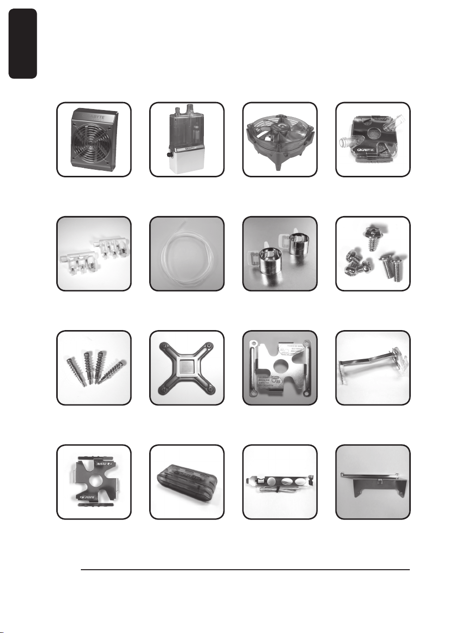
1.Accessories List
(1) Radiator (2) Pump + Tank
Assembly
X2 pcs
(5) 4 - way Splitter
Valve
X4
®
(9) Intel
Pentium® 4
LGA775 Spring
Screws
(6) 1 / 2 inch Tube (7) Tube Clips (8) Screws
(10) Intel
®
Pentium® 4
LGA775
Back
Plate
(3) MOSFET Air
Cooling Fan
X8 pcs
(11) Intel® Pentium® 4
LGA775
Bracket
(4) Waterblock
(12) AMD K8 / AM2
Clip
(13) AMD K8 / AM2
Bracket
(14) Fan Speed Con-
trol Box
(15) PCI Rear Fan
Speed
Controller
(16) Radiator Rack
X8 pcs
5
English
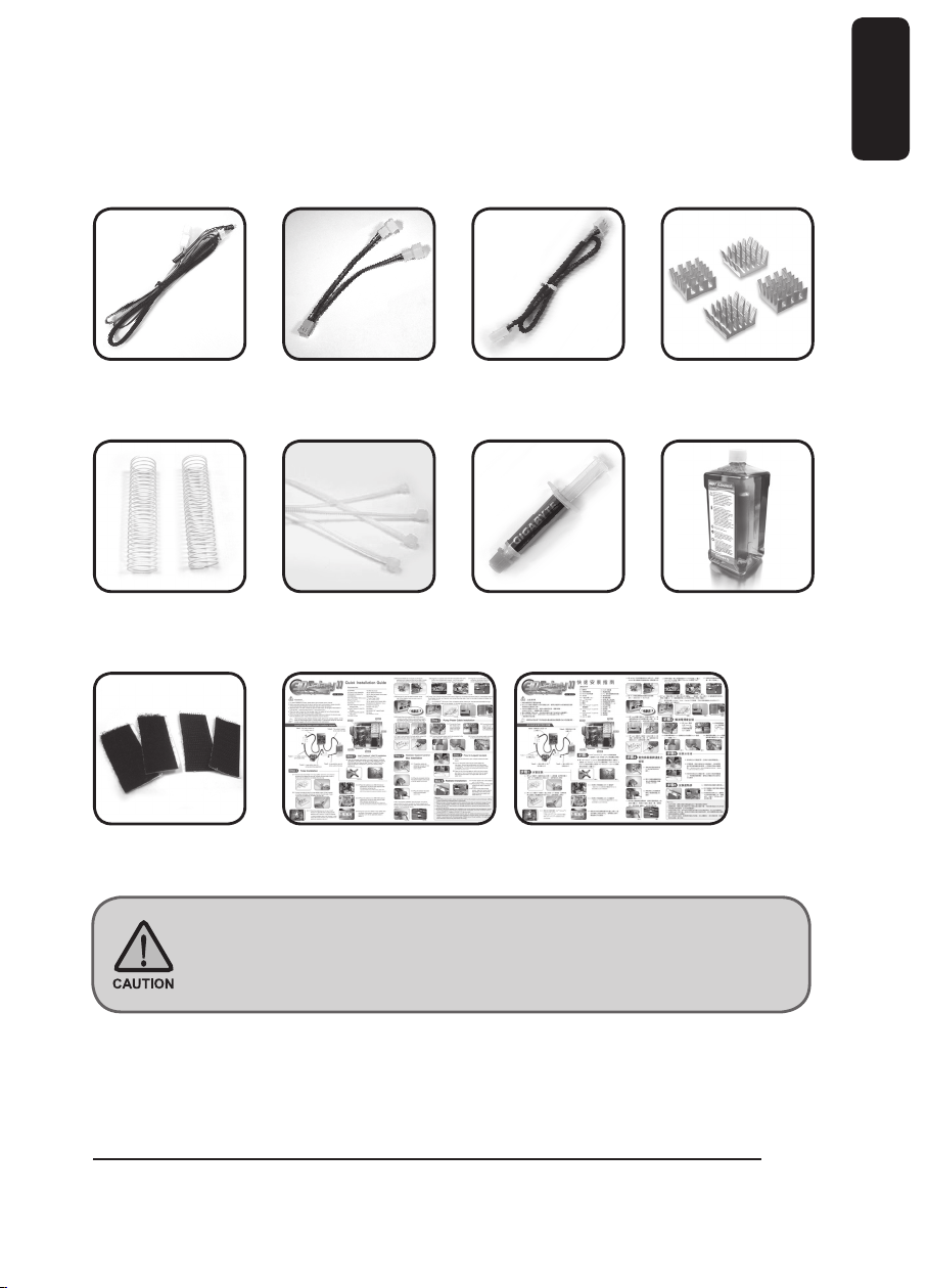
(17) Pump Power Cord (18)Fan 1 to 2 Power
Cord
X2 pcs X4 pcs
(21)Bend Proof Spring (22)Nylon Tie (23)Grease (24)Gigabyte Liquid
X2
(25)Velcro (26)Quick Installtion Guide
(19)Fan Speed
Control Power
Cord
(20)Heat Sink for
Memory
Coolant
No.8 Screw: a – Secure PCI Rear Fan Speed Controller ( 1pc )
b – Secure Radiator ( 3pcs )
c – Pump + Tank Assembly ( 2pcs )
2.Specification Instruction
Mosfet cooling fan
Fan size 80 x 80 x 25 mm
Fan speed 2000 RPM
Fan Connector 3 pin
Bearing EBR
Noise 19 dBA
Pump
Dimensions 61 x 60 x 46 mm
Maximum Capacity 400 L/hr
Noise 20 dBA
Bearing Ceramic Bearing
Life time 70000 hr (MTBF)
Radiator
Dimensions 125 x 197 x 64 mm
Material Aluminum
Fan size 120 x 120 x 25 mm
Fan speed 1200 ~ 2600RPM
Fan Connector 3 pin
Bearing 2 Ball
Noise 19~39 dBA
Tank
Dimensions 100 x 53 x 172 mm
Capacity 220cc.
Valve
Dimensions inlet:1/2”; outlet:1/4”*2,1/2”*1
Materia POM
Tube
Dimension 1/2 inch
Material PVC, UV sensitive
Coolant
Capacity 600cc.
Color Lite Blue
Compatible CPU
Intel
®
Pentium
®
Extreme Edition Series
Intel
®
Pentium
®
D Processor Series
Intel
®
Pentium
®
4 Processor Series (LGA775)
Intel
®
Core
™
2 Duo Processor Series
AMD AM2
™
Series
AMD Athlon
™
FX Series
AMD Athlon
™
64x2 Series
AMD Athlon
™
64 Series
3.Feature Instruction
1.Super huge copper base and unique water path design.
2.Long-lived, quiet and powerful ceramic bearing pump.
3.Auto-induction of low water-level ( LWP ) and over temperature ( OTP ) Protection.
4.Aluminum 4-way water path design radiator with 12 cm adjustable fan for lower noise.
6
English
5.Delicate sparkly blue LED light design tank; easy refilling coolant.
7
English
6.Well-executed liquid cooling radiator fits most existed PC chassis.
7.Multipurpose nanometer GIGABYTE
™
coolant.
8.1/2inch UV soft tube; unique design to reduce bending needs.
9.Fully support cooling solution for the surrounding component of CPU (Mosfet).
10.GIGABYTE
™
excusive 4-way splitter valve design for faster replacement and add new
cooling equipment.
11.PCI Rear Fan Speed Controller
12.Free heat sink for memory
13.Wide range use for AMD K8/AM2;Intel
<Recommended chassis to use: GIGABYTE
®
Pentium® 4 LGA 775.
™
3D Aurora, Triton, Poseidon series Chas-
sis>
4.Liquid Cooling System Installation
Please follow the instruction.
4-1 Installation Preparation
Please make sure the power of PC has been turned off.
Tool needed: scissors, GIGABYTE
™
coolant, grease, screwdriver.
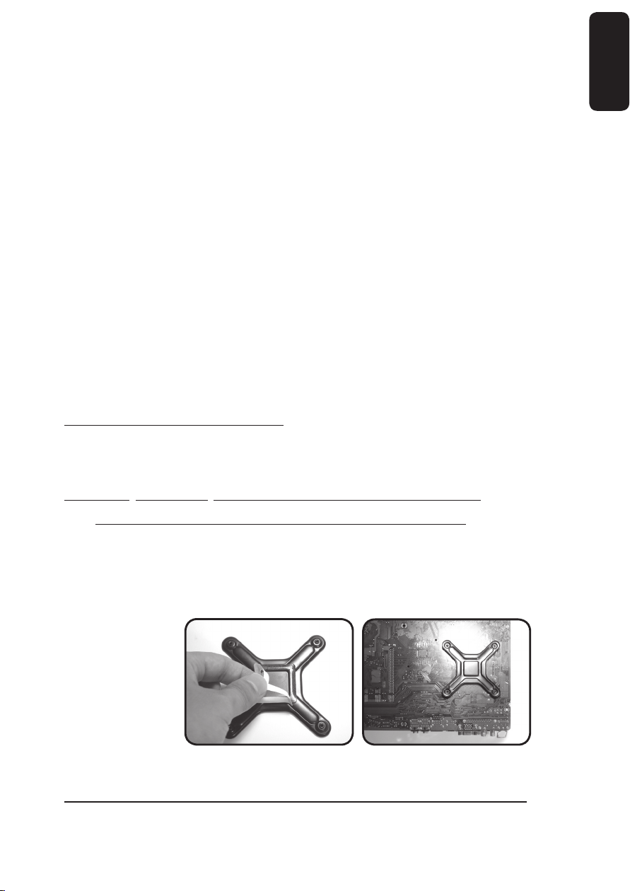
4-2 Intel® Pentium® 4 LGA775 Back Plate Installation
(For AMD series CPU, please ignore this step)
4-2-1 Take off the double-side sticker on the Intel® Pentium® 4 LGA775 Back Plate (as
Figure a), and stick it on the back of Intel
four holes on Intel
®
of Intel
Pentium® 4 LAG775 CPU motherboard (as Figure b).
®
Pentium® 4 LGA775 Back Plate and four holes on the back
Figure a Figure b
®
Pentium® 4 LGA775 CPU with aligning
8
English
4-3 PCI Rear Fan Speed Controller Installation (as Figure a/b)
4-3-1 Place PCI rear fan speed controller to the back of the chassis (place on the lower
PCI is recommended as Figure c.)
Figure a Figure b Figure c
4-4 Tube Installation
After measuring the distance between each parts of the cooling system, cut the tubes into
five suitable sizes as it shows below. To get the right length for each tube, strongly recom
mend to fit all the components in the right position.
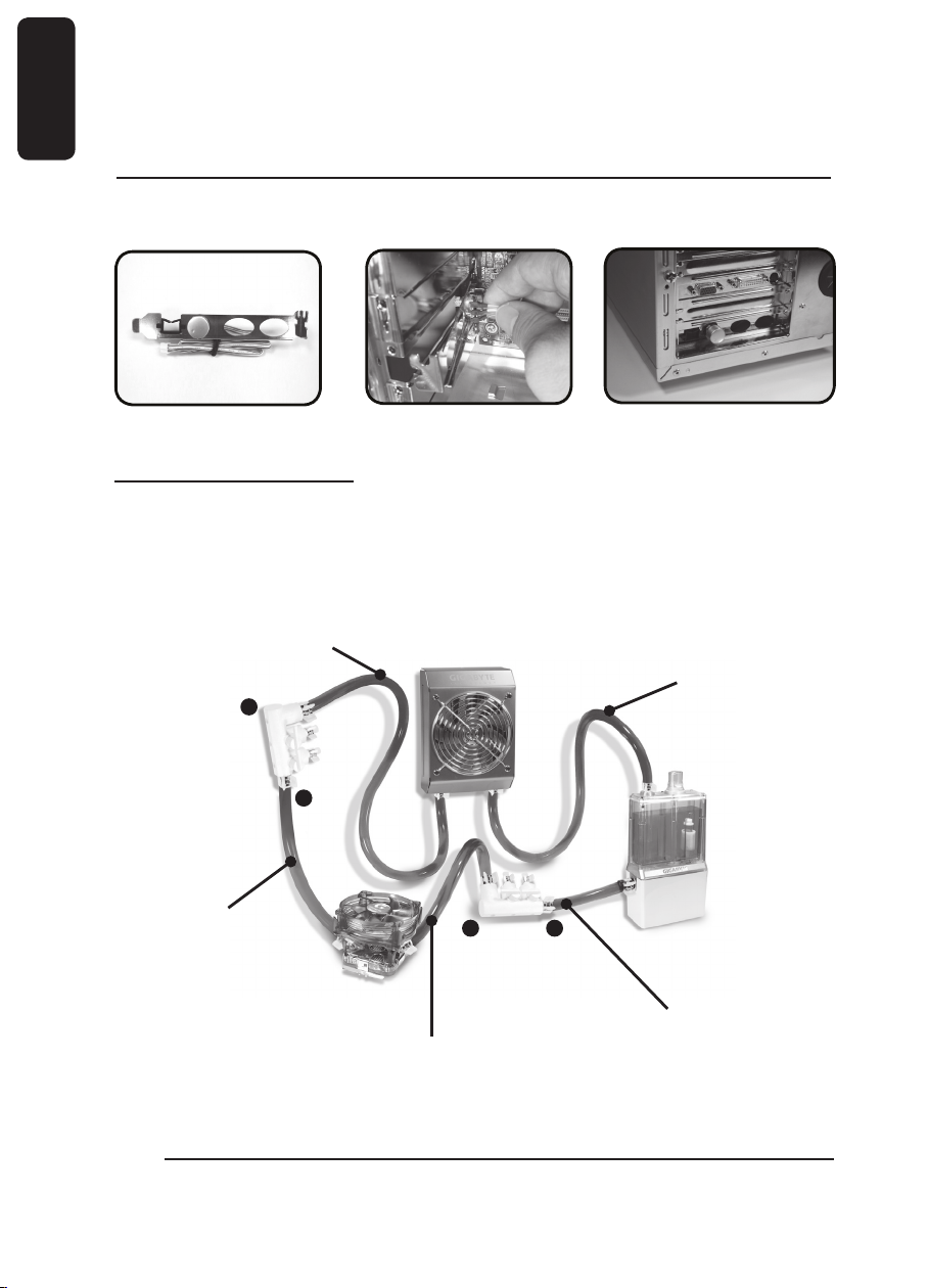
Liquid Cooling System complete installation diagram.
-
Tube3: The inlet of radiator
to 4-way splitter
valve (1)
B
A
Tube1: 4-way splitter
valve (1) to the
outlet of the
waterblock
Tube2 : 4-way splitter valve (2)
B
to the inlet of the
waterblock
Tube4: The outlet of radiator
to the inlet of the
tank
A
Tube5 : 4-way splitter valve
to the outlet of the tank
(2)
 Loading...