

Page 1
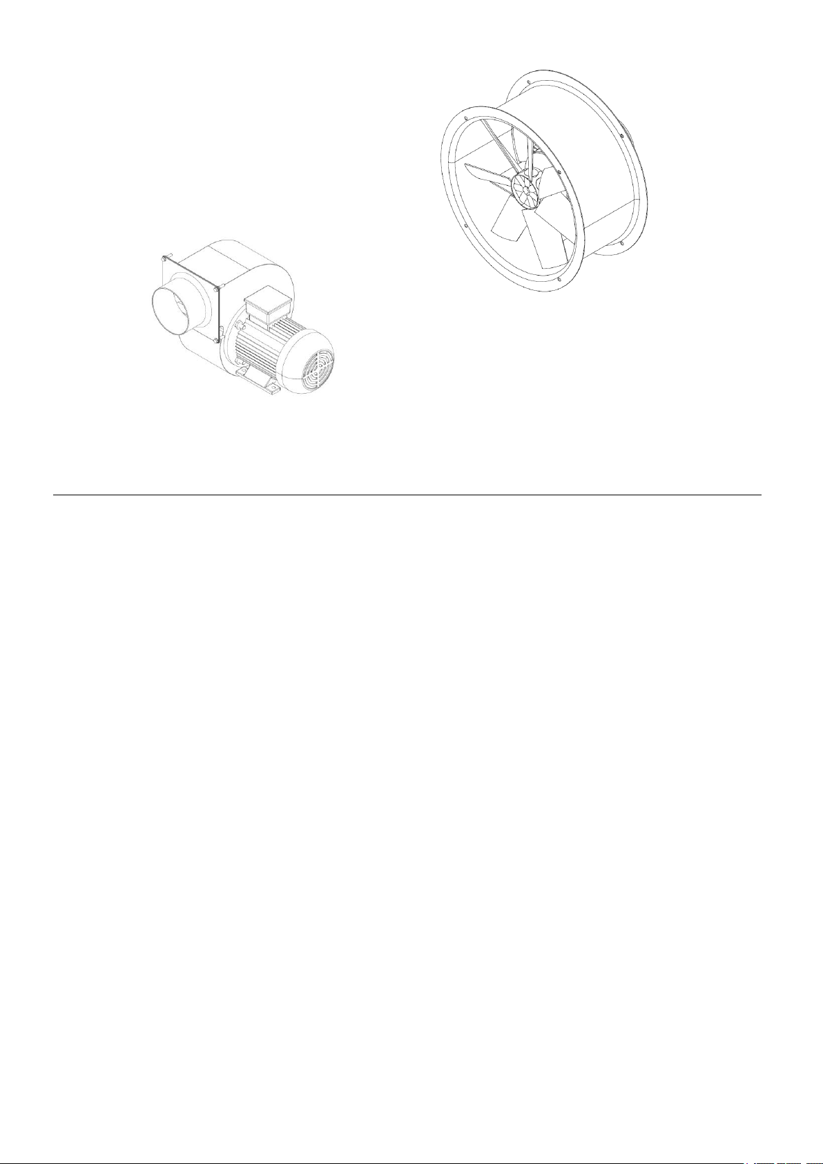
ELETTROVENTILATORI
EL/BLOWERS
C – VCP – VCR - ELL –ELL/R –
ELL/AP- EL/SR – EL/ST
MANUALE USO E MANUTENZIONE VENTILATORI CENTRIFUGHI E ASSIALI
USE AND MAINTEINANCE MANUAL FOR AXIAL AND CENTRIFUGAL BLOWERS
Ed. 02/2011
Page 2

2
MAIN INDEX
1 INTRODUCTION .............................................................................................................................. 4
1.1 PURPOSE OF THIS MANUAL ......................................................................................................... 4
1.2 GENERAL SAFETY SYMBOLS USED ............................................................................................... 4
2 GENERAL INFORMATION .............................................................................................................. 5
2.1 BASIC PRINCIPLES AND TERMINOLOGY USED ................................................................................ 5
2.2 BLOWERS AVAILABLE ................................................................................................................. 6
2.2.1 Fan orientation ...................................................................................................................... 7
3 WARNING AND MAIN SAFETY INDICATIONS .............................................................................. 8
3.1 INSTALLATION ............................................................................................................................ 8
3.2 RISKS INVOLVED IN INCORRECT HANDLING OR USE ....................................................................... 9
3.3 OTHER RISKS RELATED TO FANS................................................................................................ 10
3.3.1 Specific risk involved in transporting and installation ........................................................... 10
3.3.2 Specific risks involved in fan maintenance .......................................................................... 11
4 TRANSPORT AND INSTALLATION ............................................................................................. 12
4.1 TRANSPORT AND LIFTING .......................................................................................................... 12
4.2 STORAGE IN A WAREHOUSE ...................................................................................................... 12
4.3 LIFTING METHODS FOR FANS ..................................................................................................... 12
4.3.1 Lifting centrifugal fans C series ........................................................................................... 12
4.3.2 Lifting centrifugal fans VCP – VCR series ........................................................................... 13
4.3.3 Lifting axial fans .................................................................................................................. 13
4.3.4 Lifting fans packed in creates ............................................................................................. 14
4.4 INSTALLATION .......................................................................................................................... 14
4.4.1 Minimum distances between components .......................................................................... 14
4.5 NOTE FOR D.C. VERSION .......................................................................................................... 16
4.6 ELECTRICAL CONNECTION ......................................................................................................... 16
4.7 CONNECTIONS TO PIPES ........................................................................................................... 17
5 CHECK TO BE MADE BEFORE AND AFTER STRATING ........................................................... 17
5.1 PRELIMINARY CHECK ................................................................................................................ 17
5.2 CHECKS TO BE CARRIED OUT WITH THE FAN RUNNING ................................................................. 17
6 MALFUNCTIONS AND CAUSES .................................................................................................. 18
6.1 CENTRIFUGAL AND AXIAL FANS .................................................................................................. 18
7 MAINTENANCE ............................................................................................................................. 19
7.1 CHECKING AND CLEANING PARTS IN THE CONTACT WITH THE FLUID .............................................. 20
8 DISASSEMBLY ............................................................................................................................. 20
8.1 INTAKE NOZZLE ........................................................................................................................ 20
8.2 HOUSING ................................................................................................................................. 20
8.3 FAN ROTOR .............................................................................................................................. 20
9 SCRAPING THE FAN .................................................................................................................... 21
10 SPARE PARTS LIST ..................................................................................................................... 21
10.1 EXPLODED DRAWING .......................................................................................................... 22
10.2 BLOWER PLATE .................................................................................................................... 23
11 INTRODUZIONE ............................................................................................................................ 24
11.1 SCOPO .................................................................................................................................... 24
11.2 SIMBOLOGIA GENERALE DI SICUREZZA ....................................................................................... 24
12 GENERALITA’ ............................................................................................................................... 25
12.1 NOZIONI DI BASE E TERMINOLOGIA ............................................................................................. 25
Page 3

4
IMPORTANT: The safety measures adopted for using the fan must also
be tailored to suit the specific applications for which the fan will be used.
The safety measures taken differ depending on the type of fan
installation, as specified in paragraph 3.1.
Therefore, the information in this manual is indispensable for the use
appropriate and hazard-free use of the fan.
DANGER: This symbol indicates possible causes of personal injury
DANGER: Electrified components
IMPORTANT: This symbol indicates particularly important information of
general interest.
1 INTRODUCTION
1.1 Purpose of this manual
This manual contains instructions and warnings and constitutes the documentation that must be
supplied and kept together with the product, otherwise the product would be lacking in one of its
fundamental safety requisites.
The manual must be kept with care and made available to all persons involved in operating the
equipment.
The warning are intended to ensure the safety of persons exposed to the risks inherent in the
operation and handling of this equipment.
The instructions in this manual describe how to use the fan correctly as intended by the
manufacturer.
This manual may not, even in part, be copied, reproduced or transmitted in any form by any
electronic, mechanical, photographic or another means without the express permission of
Gianneschi Pumps and Blowers
1.2 General safety symbols used
In this manual, certain particularly important pieces of information may be preceded by one of
the following symbols:
Page 4

5
2 GENERAL INFORMATION
2.1 Basic principles and terminology used
Gianneschi Pumps and Blowers fans can be divided into the following categories:
- Radial (or centrifugal) fans: these fan are so called because the fluid enters the fan
axially and exit it radially. The fan blades can have the following different configurations:
negative (the rear, or convex face of the blade work on the fluid), positive (the front, or
concave face of the blade works on the fluid) radial (straight, the blade can work on the
fluid with the same efficiency with its front and its rear face. Neither side of the blade has
particular reinforcement).
- Axial fans: These fans are so called because the fluid enters the fan radially and exit it
axially.
Le grandezze fondamentali che caratterizzano un ventilatore sono le seguenti:
- Volumetric flow rate: This is the volume of fluid passing through the fan in a given length
of time: per second (m3/s), per minute (m3/min) or per hour (m3/h)
- Static pressure: This is the force exerted by the fan blade to overcome the resistance that
the fluid encounters as it flows through a circuit (measured in mm WC or Pascal=Pa)
- Dynamic pressure: This is the force that the fluid has due to the kinetic energy conferred
to it by the rotating fan rotor as it exits the fan outlet (measured in mm WC or Pa)
- Total pressure: This is the algebraic sum of the static pressure and the dynamic pressure
(measured in mm WC or Pa)
- RPM: This is the speed of the fan rotor in revolutions per minutes
- Efficiency: This is the ratio, expressed as a percentage, between the amount of energy
that the fan confers to the fluid and the energy supplied to the fan rotor by the motor. This
value depends on the fan rotor configuration and is dimensionless.
- Power absorptions: This is the power required (supplied by the motor) for the fan to work.
It is expressed in kW.
- Nominal motor power: This is the nominal power that the motor is able to supply. This
value must always be greater that the power absorption value for the fan, and is
expressed in kW.
- Sound pressure level: This is the energy transmitted into the outer ear, which generates
vibrations in the eardrum: in other words, this is the noise level of the fan and is
measured on the decibel A scale (this scale evaluates in relation to its frequency)
Page 5
6
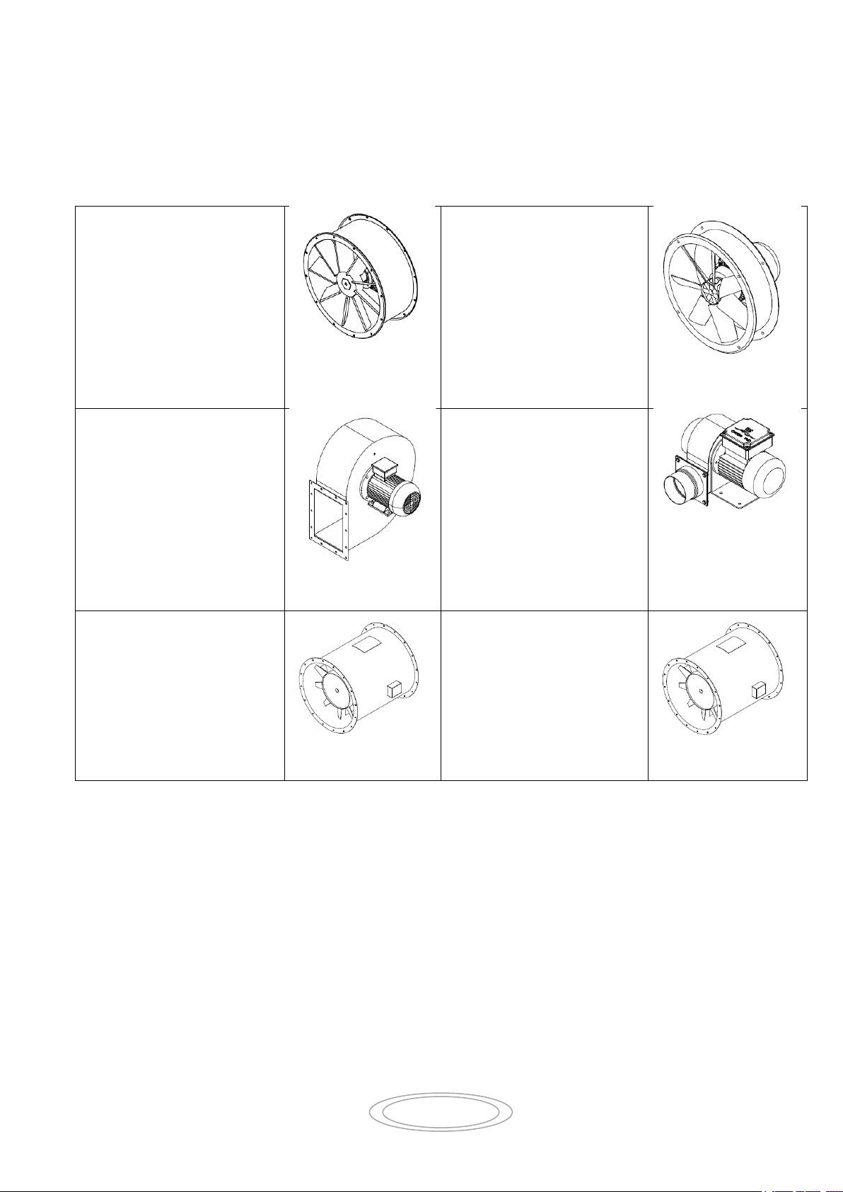
2.2 Blowers Available
ELL/AP
The axial fans ELL/AP series
use high efficiency aerofoil
profile impellers.
They are suitable for
compartments ventilation
where is required large
capacities at pressure relatively
low, like yachts and megayachts engine rooms.
ELL – ELL/R
The helicoidally “TIL – ELL –
ELL/R” blower series are built
for to obtain big air flow rates
at low pressure.
VCP – VCR
VCP series is high performance
and low noise el/blower, this
series is built to obtain high air
flow rates at medium pressure.
VCR el/blower series is similar
to VCP series but it can reach
greater values of pressure and
delivery tanks to a different
blade’s profile.
C
The “C” blowers series are built
to obtain low and medium
pressure at low and medium
flow rates.
EL-SR
Impeller is made of die cast
aluminium, aerofoil blade
profile, manual adjustable
blade angle in still position and
dynamically balanced.
EL-ST
Impeller made with an conical
collet with cast iron nozzle,
steel Fe360B formed cap,
aerofoil blade profile made in
spark-proof aluminium alloy.
Manual adjustable blade’s
orientation in still position
accurately balanced.
Page 6

7
2.2.1 Fan orientation
Centrifugal fans can be built in 16 different orientations ( 8 rotated clockwise, RD and 8 rotated
anticlockwise, LG) The orientations of a fan is expressed as seen from the transmission side.
Orientations RD LG 180 and 225 are only possible if special mechanical modifications are
made.
Fig. 2.1 Fan orientation
Centrifugal Blower Orientation Axial Blower Execution
Page 7

8
There are four possible installation types, in compliance with UNI 12499:2009
specifications
- Type A: open intake and outlet
- Type B: open intake and outlet connected to pipe
- Type C: intake connected to a pipe and open outlet
- Type D: intake and outlet connected to a pipe
WARNING:
Check all safety guards regularly to make sure they are efficient and
replace promptly in case of damage or breakage.
3 WARNING AND MAIN SAFETY INDICATIONS
3.1 Installation
Clearly Gianneschi Pumps and Blowers cannot be aware of which of these four installation types
will be used by the user. Therefore, the installer or end client themselves must analyse the risk
involved for the chosen installation type used in the specific applications.
Depending on the applications that the client intends to use the fan for in the factory and on the
type installation chosen, the following safety shield must be fitted:
- Type A Installation: fixed shield at the intake and outlet
- Type B Installation: shield fitted only at the outlet
- Type c Installation: shield fitted only at the intake
- Type A Installation: no shield at either the intake or outlet.
The user or the installer of the fan must censure that adequate shielding is fitted to the pipe
system at the point where it connects to the working pipes, as follows:
- Type A installation: no shield necessary
- Type B Installation: shield fitted to the outlet pipe
- Type C Installation: shield fitted to the intake pipe
- Type D Installation: shields fitted to the intake and outlet pipes
The shielding must be constructed to impede access to the parts of the fan that could cause
injury. It must be robustly built enough to stand the vibrations and stress caused by the machine
and by environmental conditions. It must be securely fixed in position by devices that will not
become loosened by vibrations and that cannot be removed without the use of tools.
It is, in any case, the person installing the fan who is responsible for ensuring that adequate
measures have been taken to prevent accidental contact with the fan’s moving parts. The user
must also bear in mind the risk inherent in maintenance work, which must always be with the
fan separated from the motor or isolated using suitable equipment.
Page 8
9
Once the installer and/or user has decided which installer type is to be used and all the above
procedures have been applied, the machine can now be considered a “complete machine” as
describe by machinery directive 2006/42/CE use regulations.
3.2 Risks involved in incorrect handling or use
Never, for any reason whatsoever, disable, remove, modify or render in operative in any
other way any of the safety, protective or control devices of any single component or of the
fan itself
Never place hands, arms or any other parts of the body near any moving part
Never extended any part of the body past the limits of the safety barriers. Do not use any
means that will increase normal accessibility to the fan components
Never use the fan (in standard condition) in atmospheres where there is a risk of explosion
Unauthorised operators must not attempt to rectify any malfunction of the fan and/or modify
the functional characteristics or installation type
After any un programmed maintenance operation that required the removal of shield,
barriers or any other protective device, before restarting the fan ensure that all these
components have been refitted and are fully functional
All protective and safety devices must be kept in perfect working order at all times. All
indicative and warning plates fixed to the fan must also be kept in perfect condition at all
times and must never be removed or moved from their original position
When troubleshooting for the cause of any malfunction of the fan, ensure that all precautions
described in this manual have been taken to prevent personal injury and/or damage to
property
Remember to tighten every screw, bolt and lock ring of every component subject to
adjustment or maintenance
Before starting the fan, ensure that all safety devices have been correctly installed and are in
perfect working order; if the above is not the case, do not start the fan and inform the head
of safety or department manager immediately
The operator must be equipped with Personal protection Equipment in accordance with
current legislation; the use of bulky clothing and accessories (ties, loose sleeves, etc.) is
prohibited.
Page 9

10
3.3 Other risks related to fans
The following is a list specific hazards related to the fan’s mechanical characteristics
A persons may receive injuries as a result of:
a) Becoming caught up between a moving part and a stationary part, for example, between a fan rotor and
the fan housing or any other stationary fan component
b) Becoming caught up between two moving parts.
c) Suction of a part of the body into the fan and subsequent contact with the shaft or rotor
d) Contact with a moving part, such as the rotor
e) An object becoming sucked into the intake of the fan and expelled at high speed from the otlet of the
fan
f) Contact with surface of the fan at dangerous temperatures for example temperatures below –20°C or
above +50°C
g) Hazard caused by the over speed of a fan component, which can lead to the breakage of part of the
machine
The aspiration of air at temperatures above the specified operating range, which can lead to the
deformation and breakage of the housing.
3.3.1 Specific risk involved in transporting and installation
Before installation the user must prepare a perfectly level surface onto which the fan will be
mounted. If this surface is not perfectly level, this can cause abnormal vibrations in the fan.
This can over time lead to the deformation and/or breakage of fan components with the
subsequent expulsion at speed of broken parts: these expelled parts can cause even fatal
injuries to any persons exposed
Before installation, the user must also prepare adequate connections to earth for the fan
case or for the fan structure to prevent the build-up of electrostatic charges.
All installed protective devices must remain fixed to the fan together with their respective
fixings (screw, bolt, etc.) The removal of one or more fixing may compromised the
functionality and tightness of the safety shield.
In its standard form, the fan is not intended for use in a potentially explosive environment.
The installation location of the fan must be kept clean at all times. Any eventual oil or water
spillages not caused by the fan must be removed immediately.
The minimum installation distances specified in the manual must always be respected to
ensure correct functionally without any further hazards. The incorrect positioning of a
component can compromise the functionality of the fan.
Page 10
11
3.3.2 Specific risks involved in fan maintenance
During maintenance and cleaning of the fan rotor, be particular careful of the rotation of the
rotor. This can lead to parts of the body becoming trapped and seriously injured between the
rotor itself and fixed parts of the fan housing.
Even when the fan is disconnected from the power supply, the rotating parts can still turn
due to any air movement through the fan. This air flow may be natural or may be caused by
the current induced by another fan installed elsewhere in the connected tubing system. This
can also lead to parts of the body becoming trapped and seriously injured between the rotor
itself and fixed parts of the fan housing.
A fan maintenance program must be draw up and followed to prevent the mechanical failure
or breakage due to wear or insufficient maintenance.
DANGER: IT IS ABSOLUTELY FORBIDDEN TO:
Carry out any maintenance work without first ensuring
g that the fan rotor is effectively stationary.
Start any maintenance work on the fan (including lubrication) without first disconnecting the fan from
the mains power supply.
Clean the fan while it is running.
Open any shield or inspection hatch while the fan is running.
Page 11
12
THERE USER IS RESPONSIBLE FOR THE SELECTION OF EQUIPMENT,
ROPES, AND CHAINS BEST SUITED FOR BOTH LOAD AND
FUNCTIONALITY.
4 TRANSPORT AND INSTALLATION
Lifting and manoeuvring the fan may crate hazards for any persons in the vicinity it is therefore
important to follow the indications given by Gianneschi Pumps and Blowers and use suitable
equipment.
4.1 Transport and lifting
Therefore, all operation involving the lifting and manoeuvring of the fan must be carried out with
the utmost caution, avoiding any knocks that could compromise the functionality or damage the
fan component.
4.2 Storage in a warehouse
Should it be necessary to store the fan in a warehouse, it must be protected from atmospheric
conditions, humidity, dust and any harmful substances present in the air.
We recommend that you periodically check that the fan is in a good condition and turn the fan
rotor manually approximately once a month to prevent the deformation of its bearings
4.3 Lifting methods for fans
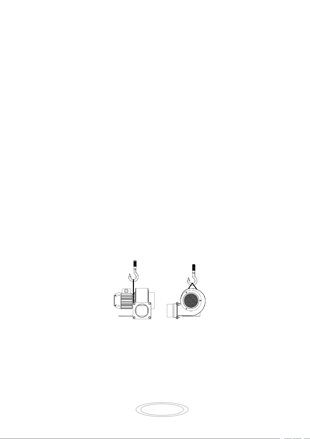
4.3.1 Lifting centrifugal fans C series
Fans C series are equipped with a motor without the specific holes similar VCP – VCR series,
you must connect the lifting belt under the electric motor (as shown Fig. 4.1)
Fig. 4.1 Example of lifting centrifugal fans C series
Page 12
13
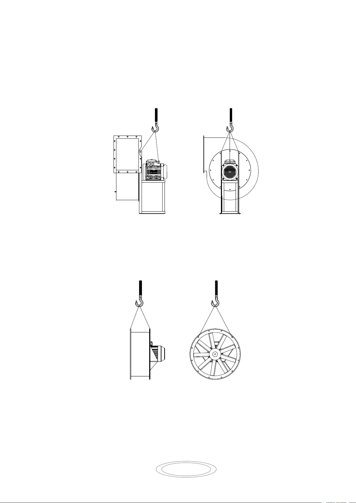
4.3.2 Lifting centrifugal fans VCP – VCR series
Fans VCP-VCR series are equipped with a motor. When lifting these fans, as well as using the
specific holes in fan structure, the eyebolt for lifting the motor must also be used (as shown Fig.
4.2)
Fig. 4.2 Example of lifting centrifugal fans VCP – VCR series
4.3.3 Lifting axial fans
Fig. 4.3 Example of lifting axial fans
Page 13

14
4.3.4 Lifting fans packed in creates
ALWAYS USE ANTI-VIBRATION SUPPORT AND COUPLING TO PREVENT
TRANSMISSION OF VIBRATIONS WHILE THE FAN IS RUNNING.
ALL INSTALLATION WORK MUST ONLY BE CARRIED OUT BY QUALIFIED AND
AUTHORISED PERSONNEL USING SUITABLE EQUIPMENT
Fig. 4.4 Example of lifting fans packed in creates
4.4 Installation
The fan does not required the preparation of a special machine bed for its installation. A welllevelled surface that can support the weight of the fan is sufficient.
The support base must be perfectly level and flat to prevent any torsion effects or misalignment
of the supports: if necessary, install metal shims between the machine base and the surface to
censure a perfect.
All connecting tubing must be supported separately and must be axially aligned with the fan’s
intake and outlet nozzles, to prevent any deformation occurring while tightening the bolts.
4.4.1 Minimum distances between components
If the available space permits, in installations where the intake is connected to a pipe we
recommend fitting a straight length of pipe with a length approximately 2.5 times the diameter of
the fan rotor, to guarantee correct air flow into the intake
Page 14

15
WARNING: ALL TRANSPORT, INSTALLATION AND ASSEMBLY OPERATIONS MUST ONLY
BE CARRIED OUT BY QUALIFIED PERSONNEL
WARNING: DISCONNECTED OR DISASSEMBLED COMPONENTS MUST ONLY BE
HANDLED AND MANOEUVRED USING SUITABLE TRANSPORT EQUIPMENT
Fig. 4.5 Minimum installation distances with intake pipe
With installation with an open air intake, we recommend leaving a distance equal to
approximately 1.5 times the diameter of the fan rotor between the fain intake and the nearest
wall or machine.
Fig. 4.6 Minimum installation distances with open intake
General warning for lifting and installing parts disconnected from the fan for shipping
For transport purposes, the fan may be delivered with a number of its components
disconnected.
Page 15

16
USUALLY NO SPECIAL OR DEDICATED EQUIPMENT IS REQUIRED FOR
LIFTING AND REFITTING THE FAN COMPONENTS.
SHOULD THE INSTALLATION OF A COMPONENT REQUIRED A SPECIAL
PROCEDURE, Gianneschi Pumps and Blowers WILL SUPPLY THE
SUPPLEMENTARY INFORMATION NEEDED FOR A CORRECT INSTALLATION.
CAUTION: THE CLIENT AND/OR THE INSTALLER OF THE ELECTRIC SYSTEM
IS RESPONSIBLE FOR CHOOSING THE EQUIPMENT AND CABLES USED FOR
CONNECTING THE FAN ELECTRICALLY, BASED ON THE DIMENSIONS OF THE
MOTOR INSTALLED AND THE CHARACTERISTICS OF THE MAINS POWER
SUPPLY
4.5 Note for D.C. Version
- Check periodically the brushes wear
- The voltage increase (<24V) may cause the increasing of the speed rotation and the
power absorption increment.
- Excessive power absorption may cause the engine overheat
- Before starting operation check the power supply
For more details please consult the D.C. motors manual.
4.6 Electrical connection
The fan’s power supply line must have a sufficiently high power rating.
Connection to the mains power grid must only be carried out by qualified personnel. Also, the
client is responsible for the entire electrical system up to motor terminal board.
We remind you of the importance of installing a safe connection to earth for the fan.
The earth connection system must comply with legislation in effect in the country of installation
and must be periodically checked by qualified personnel.
Make the connection to earth before any other connection
Check that the connection layout (see fig. 4.7) is suitable to the mains power voltage.
Usually, standard electric motors can run in both directions indifferently. To invert the direction
of rotation, simply swap over any two power cables directly on the terminal box.
The client must also install an electrical disconnecting device near the fan so that maintenance
personnel can have direct control over the power supply to the fan.
All work performed on the electrical system must only be carried out with the fan at rest and
electrically disconnected from the mains.
Before installing/starting up, ensure that the information on the identification plate on the motor
is compatible with the mains power supply.
Page 16
17
PRELIMINARY CHECKS MUST ONLY BE PERFORMED WITH THE FAN AT REST AND
DISCONNECTED FROM THE POWER SUPPLY
4.7 Connections to pipes
Connections between the fan and pipes must be made ensuring that all components are
correctly aligned and that there are no obstruction in the tubing caused by gaskets or flexible
parts. The weight of the tubing must not be supported by the fan and care must be taken not to
deform any part of the fan during tightening of the connections to the pipes.
5 CHECK TO BE MADE BEFORE AND AFTER STRATING
5.1 Preliminary check
When starting the fan for the first time, the following preliminary checks are necessary
Check the lubrication of the fan and motor bearing; if necessary, degrease
Check that all rotating parts can turn freely
Check that there are not foreign object inside the fan
Check that the fan turns in the correct direction: power the motor for a brief moment to see if
it turns in correct direction indicated by the arrow on the fan housing: if necessary, invert the
direction of rotation (see electrical connection)
You may now start the fan. With centrifugal fans, close off the air intake partially to reduce the
power peak at the start-up and the motor starting time. Axial fans must never be run with
completely closed nozzles
5.2 Checks to be carried out with the fan running
Check that the power absorption does not exceed the value indicated on the motor identification
plate, if it does, stop the fan immediately and contact the manufacturer.
The fan must run without excessive vibration and noise.
Check, with the fan at rest and at an outside air temperature of 20°C, that the bearing do not
exceed the maximum operative temperature (maximum bearing temperature 70°C). During the
first few hours of operation, it is normal for the bearings to reach slightly higher temperatures, as
long as they later stabilise at a lower value. In the event of overheating of the bearings, contacts
the Gianneschi Pumps and Blowers technical assistance department.
Page 17
18
PROBLEM
REASON
CAUSE
Power absorption much lower
than nominal value
Insufficient air flow
(centrifugal fans only)
Rotational speed too low
Nozzle or tubing partially obstructed
(centrifugal fans only)
Fan rotor partially obstructed (centrifugal
fans only)
Pressure resistance offered by the system
higher than the design value (centrifugal fans
only)
Inverted direction of rotation (centrifugal fans
only)
High power absorptions
Excessive air flow
(centrifugal fans only)
Excessive rotational speed
Pressure resistance offered by the system
lower than the design value (centrifugal fans
only)
High power absorptions
Air flow already rotating in the opposite
direction to the fan rotation direction
Motor power supply voltage lower than
the value indicated on the identification
plate
Faults in the motor windings
Air flow value lower than the design
value (axial fans only)
Insufficient pressure
Rotational speed to low
Inverted direction of rotation (axial fans only)
Air flow value higher than the design value
(axial fans only)
Fluctuating fan operation
Unstable air flow
Low air flow
Fluctuations in air flow due to fans working in
parallel
Vortices in the air induced by equipment near
the air intake
Vibrations
Fluctuating fan operation
(See previous cause)
Vibrations
Unbalanced rotating components
Fan rotor wear
Deposits on the fan rotor
Vibrations
Mechanical malfunction or defects
Contact between moving and stationary
components
Intrinsic fault in the bearing
Malfunction of the bearings due to
unbalanced rotor or excessive belt tension
Excessive noise
Contact between moving and stationary
components
Vibrations
Fluctuating fan operation
Electromagnetic fault in motor
Orifices or sharp angles in tubing
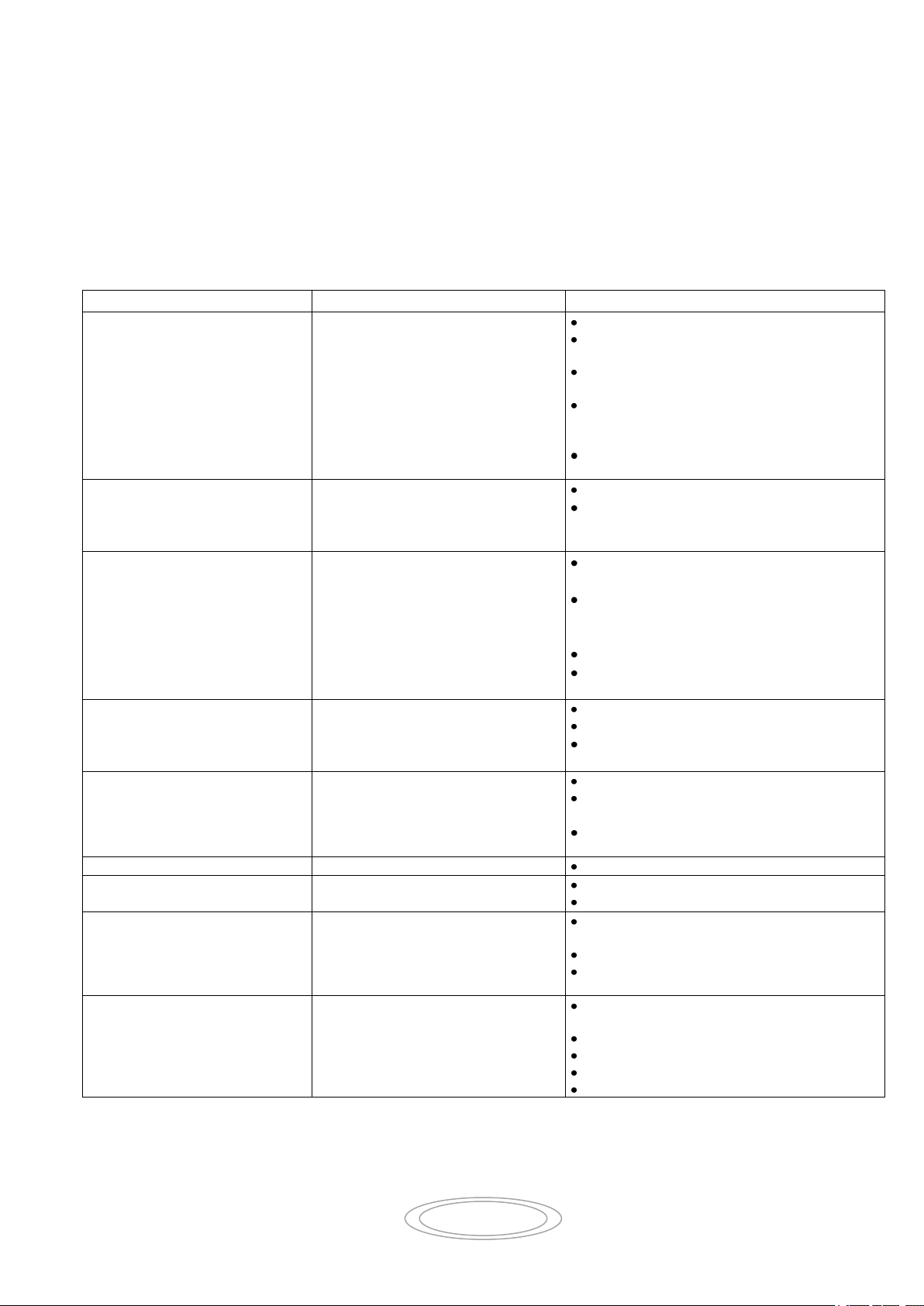
6 MALFUNCTIONS AND CAUSES
6.1 Centrifugal and axial fans
The following table lists the main problems that you may encounter using a fan. For problems
that are not common to both types of fan, we have specified whether it is specific to centrifugal
or axial fans.
Page 18

19
CAUTION: ANY TRANSPORTING OPERATION OF PARTS DISMANTLED FROM
THE FAN OR TO BE FITTED TO THE FAN MUST ONLY BE CARRIED OUT
WITH SUITABLE TRANSPORT EQUIPMENT
USUALLY, NO SPECIAL OR DEDICATED EQUIPMENT IS REQUIRED FOR LIFTING AND
REFITTING THE FAN COMPONENTS
AN INTEGRATED MAINTENANCE PROGRAM IS NECESSARY FOR NORMAL AND CORRECT
OPERATION OF THE FAN, AND ALSO ENSURES GREATER SAFETY FOR THE OPERATOR
REGULAR CLEANING AND MAINTENANCE, TOGETHER WITH LUBRICATION, ARE VITAL FOR
ENSURING CORRECT OPERATION AND GREATER DURABILITY OF THE FAN
7 MAINTENANCE
Read this section carefully before starting any maintenance work on the fan: these
indications will censure safer working conditions for the personnel involved and more
reliable results of the maintenance work carried out.
Safety procedures adopted during fan maintenance must take into account the following:
Maintenance and lubrication operations must only be carried out by qualified and export
personnel, authorised by the factory technical management department in accordance
with safety directives and regulations and using only suitable tools, equipment’s and
materials for the job.
While performing maintenance work, all personnel involved must wear appropriate
clothing, such as tight fitting works overalls and accident prevention shoes. Loose fitting
clothes with hanging parts must be avoided at all costs.
During maintenance, cordon off the fan and place signs around the fan indicating “FAN
UNDERGOING MAINTENANCE”
During any maintained procedure, the fan must be:
Disconnected and insulated from the electric power supply
Disconnected from elastic coupling to the motor, if fitted
The head of maintenance must set up a team made up of persons capable working in a
coordinate fashion and ensuring the utmost safety of those surrounding them. All persons
involved in maintenance must be in constant visual contact among themselves to be able warn
each other of any hazards present.
Page 19

20
ALL THE DISASSEMBLY AN RE-ASSEMBLY OPERATIONS DESCRIBED BELOW
MUST ONLY BE CARRIED OUT BY QUALIFIED AND AUTHORISED PERSONNEL.
FOR NO REASON WHATSOEVER MUST THE OPERATOR OR FACTORY
MAINTENANCE PERSONNEL CARRY OUT THESE OPERATIONS.
7.1 Checking and cleaning parts in the contact with the fluid
The fan rotor should be cleaned regularly to prevent vibration caused by dust accumulating on
the blades during operation.
If the fan is used to pump even slightly dusty air, air containing abrasive powders or for the
pneumatic transport material, the cleanliness and wear of the fan rotor must be checked
regularly.
Dirt deposits on the rotor or wear of parts of the rotor can cause undesirable vibration during fan
operation.
If any part of the rotor is excessive worn, it is imperative that the rotor be replaced.
8 DISASSEMBLY
caution: all disassembly and re-assembly work must be carried out with the following
conditions:
a) you must be absolutely certain that the fan is completely stationary (fan rotor at rest);
disconnect the electrical power at the main panel with a padlock and hand the key of
the lock to the head of maintenance
b) The working environment must be equipped with every tool necessary and must be
free of any hazards
c) every piece to be refitted must be thoroughly cleaned, degreased and lubricated as
necessary before refitting
8.1 Intake nozzle
Undo the nozzle securing nuts from the fan housing. Slide out the nozzle.
8.2 Housing
With all orientable fans, the housing is secured to the frame by bolts. Simply undo the securing
nuts at the frame plate.
With non-orientable fans with single-piece housings, the housings cannot be disassembled.
The housing in certain fan types may be divided into two or more pieces, secured together by
bolts.
8.3 Fan rotor
Remove the nozzle and, where possible, the fan housing.
With single intake fan: remove the screw together with the lock ring and use a suitably sized
extractor.
We recommend setting up a support for the rotor before extracting it completely.
Page 20

21
9 SCRAPING THE FAN
At the end of the fan’s useful life, the user company is responsible for scraping the fan, taking
care in particular of emptying all lubricating liquids, generally cleaning all components and then
separating the fan’s parts into components and electrical material. Different materials must be
collected separately, for example: electric motors (copper winding), metal components
(structural components, etc.) plastics, etc., and then correctly disposed of separately.
10 SPARE PARTS LIST
AXIAL BLOWERS
1. Fan Fixing Screw
2. Grower
3. Washer
4. Impeller
5. Blower Case
6. Nut
7. Washer
8. Screw
9. Motor
CENTRIFUGAL BLOWERS
1. Screw
2. Inlet Connection
3. Protection Grate
4. Impeller Screw
5. Grower
6. Washer
7. Impeller
8. Spacer (Only ATEX version)
9. Bolt
10. Blower Casing
11. Nut
12. Discharge Connection
13. Screw
14. Nut
15. Motor With Flange
Page 21

22
10.1 EXPLODED DRAWING
Page 22

23
10.2 BLOWER PLATE
The identification plate is the only means of fan identification recognized by the manufacturer. It
must not be modified
IMPORTANT: When you order a new spare parts. Always indicate the serial number
Page 23
44
ELL, ELL/R, ELL/AP, EL/SR, EL/ST Ventilatori / Blowers
DICHIARAZIONE DI CONFORMITA’
Ai sensi dell’ allegato II della direttiva macchine 2006/42/CE e successivi emendamenti.
Il sottoscritto costruttore:
GIANNESCHI Pumps and Blowers S.r.l.
Dichiara sotto la propria responsabilità che gli elettroventilatori assiali serie:
ELL, ELL/R, ELL/AP, EL/SR, EL/ST, e loro derivati,
destinate alla movimentazione di aria pulita in ambienti ove non vi sia il pericolo di esplosione sono conformi
a quanto prescritto dalle direttive:
DIRETTIVA MACCHINE (MSD) 2006/42/CE
DIRETTIVA BASSA TENSIONE (LVD) 2006/95/CE
e successivi emendamenti.
È fatto divieto di mettere in servizio gli elettroventilatori, oggetto di questa dichiarazione, prima che
l’impianto o il sistema in cui sarà incorporato sia stato dichiarato conforme alle disposizioni delle
direttive vigenti e ai regolamenti di classe applicabili.
Dichiara inoltre che la marcatura è apposta sulla targhetta del prodotto.
DECLATATION OF CONFORMITY
Under Annex II of the Machinery Directive 2006/42/CE as amended.
The undersigned manufacturer:
GIANNESCHI Pumps and Blowers S.r.l.
Declare on own and exclusive risk, that the axial blowers series:
ELL, ELL/R, ELL/AP, ELL/SR, ELL/ST, and their derivate,
Suitable for move clean air and to work in not danger of explosion areas are conformity with the provisions
of:
MACHINERY DIRECTIVE (MSD) 2006/42/CE
LOW VOLTAGE DIRECTIVE (LVD) 2006/95/CE
and subsequent amendments.
It’ is forbidden to operate the blowers referred to in this declaration before the finished product in
each it will be incorporated or assembled has been declared to be in conformance with the directive
in force and class rules applied.
It also declares that the marking is affixed in the product plate.
Page 24
45
C, VCP, VCR Ventilatori / Blowers
DICHIARAZIONE DI CONFORMITA’
Ai sensi dell’ allegato II della direttiva macchine 2006/42/CE e successivi emendamenti.
Il sottoscritto costruttore:
GIANNESCHI Pumps and Blowers S.r.l.
Dichiara sotto la propria responsabilità che gli elettroventilatori centrifughi serie:
C, VCP, VCR, e loro derivati,
destinate alla movimentazione di aria pulita in ambienti ove non vi sia il pericolo di esplosione sono conformi
a quanto prescritto dalle direttive:
DIRETTIVA MACCHINE (MSD) 2006/42/CE
DIRETTIVA BASSA TENSIONE (LVD) 2006/95/CE
e successivi emendamenti.
È fatto divieto di mettere in servizio gli elettroventilatori, oggetto di questa dichiarazione, prima che
l’impianto o il sistema in cui sarà incorporato sia stato dichiarato conforme alle disposizioni delle
direttive vigenti e ai regolamenti di classe applicabili.
Dichiara inoltre che la marcatura è apposta sulla targhetta del prodotto.
DECLATATION OF CONFORMITY
Under Annex II of the Machinery Directive 2006/42/CE as amended.
The undersigned manufacturer:
GIANNESCHI Pumps and Blowers S.r.l.
Declare on own and exclusive risk, that the centrifugal blowers series:
C, VCP, VCR, and their derivate,
Suitable for move clean air and to work in not danger of explosion areas are conformity with the provisions
of:
MACHINERY DIRECTIVE (MSD) 2006/42/CE
LOW VOLTAGE DIRECTIVE (LVD) 2006/95/CE
and subsequent amendments.
It’ is forbidden to operate the blowers referred to in this declaration before the finished product in
each it will be incorporated or assembled has been declared to be in conformance with the directive
in force and class rules applied.
It also declares that the marking is affixed in the product plate.
Page 25

46
SUPPLEMENTO ALLA DICHIARAZIONE DI CONFORMITA’
SOLO PER MOTORI IN C.C.
La sottoscritta ditta GIANNESCHI Pumps and Blowers S.r.l.
dichiara che i ventilatori serie C ed ELL rispettano i contenuti della norma ISO 9097 ad eccezione di quanto
richiesto nel punto 4.2.
Come infatti indicato nel manuale uso-manutenzione dei prodotti
IL DISPOSITIVO NON PUE’ ESSERE AZIONATO IN ATMOSFERA ESPLOSIVA,
e pertanto si ritiene tale requisito non applicabile (RIF. ISO 8846 – Punto 1).
È fatto divieto di mettere in servizio gli apparecchi, oggetto di questa dichiarazione, prima che la
macchina o il sistema in cui sarà incorporato sia stato dichiarato conforme alle disposizioni delle
direttive vigenti e i regolamenti di classe
IN ADDITIONAL TO THE CONFORMITY DECLARATION
ONLY FOR D.C. MOTORS
The undersigned manufacturer GIANNESCHI Pumps and Blowers S.r.l.
Declare that the blowers series C and ELL obey the standard into a ISO 9097 except the point 4.2
As indicated in the instruction manuals
THE BLWER CAN’T BE START IN EXPLOSIVE ATMOSPHERE
And therefore considerer that requirement not applied
It’ is forbidden to operate the blowers referred to in this declaration before the finished product in
each it will be incorporated or assembled has been declared to be in conformance with the directive
in force and class rules applied.
Page 26

47
Page 27

48
NOTE:
_____________________________________________________________
_____________________________________________________________
_____________________________________________________________
_____________________________________________________________
_____________________________________________________________
_____________________________________________________________
_____________________________________________________________
_____________________________________________________________
Blower Plate
ASSISTENZA – SERVICE
Gianneschi Service S.r.l.
Via dei Calzolai 2/b 55041 Capezzano Pianore (LU) ITALY
Tel.: +39 0584-361087 (r.a.) Fax: +39 0584 361088
E-Mail: [email protected]
Gianneschi Pumps and Blowers S.r.l. - Via G. Pastore, n°19/21
55040 Capezzano Pianore (LU) - ITALIA
Tel.: +39 0584 969391 Fax: +39 0584 969411
Cod. FIS. e P.IVA IT: 01619620469 – (REA 154940 Lucca) – Cap. Soc. 54.000 €
Web site: www.gianneschi.net; E-Mail: [email protected]
 Loading...