

Page 1

FasTrack
Cutter
Owner's Guide
TM
Page 2

COPYRIGHT NOTICE
COPYRIGHT 1999 Gerber Scientific Products, Inc. All Rights Reserved.
This document may not be reproduced by any means, in whole or in part, without written permission of the
copyright owner.
This document is furnished to support the FasTrack™ Cutter. In consideration of the furnishing of the
information contained in this document, the party to whom it is given assumes its custody and control and
agrees to the following:
1. The information herein contained is given in confidence, and any part thereof shall not be copied or
reproduced without written consent of Gerber Scientific Products, Inc.
2. This document or the co nt ents herein under no circumstances sh all be used in the manufacture or
reproduction of the article shown and the delivery of this document shall not constitute any right or
license to do so.
Information contained in this document is subject to change without notice.
Printed in USA
GRAPHIX ADVANTAGE and GSP are registered trademarks and FasTrack is a trademark of Gerber
Scientific Products, Inc. HPGL is a trademark of Hewlett-Packard Company. Windows is a registered
trademark of Microsoft Corporation in the U.S. and other countries. MS-DOS and Microsoft are registered
trademarks of Microsoft Corporation. HPGL is a trademark of Hewlett-Packard Company.
Page 3

FCC WARNING
This equipment has been tested and found to comply with the limits for a Class A digital device, pursu ant to
Part 15 of the FCC rules. These limits are designed to provide reasonable protection against harmful
interference when the equipment is operated in a commercial environment. This equipment generates, uses,
and can radiate radio frequ ency energy and, if not installed and used in accordance with the inst ruction
manual, may cause harmful interference to radio communications. Operation of this equipment in a
residential area is likely to cause harmful interference in which case the user will be required to correct the
interference at his own risk.
This digital apparatus does no t exceed the Class B limits for radio noise emissions from digital apparatus set
out in the Radio Interference Regulations of the Canadian Department of Communications.
Le present appareil numerique n'emet pas de bruits radioelectriques depassant les limites applicables aux
appareils numeriques de la classe B prescrites dans les Reglements sur le brouillage radioelectrique edicte par
le Ministere des Communications du Canada.
Page 4

Page 5

TABLE OF CONTENTS
INTRODUCTION............................................................................................................. 1
ATTENTIONS AND CAUTIONS............................................................................................................ 1
CUSTOMER SUPPORT ........................................................................................................................ 2
CHAPTER 1 INSTALLATION PROCEDURES .............................................................. 4
PREPARING THE CUTTER ENVIRONMENT....................................................................................... 4
UNPACKING AND SETTING UP THE CUTTER................................................................................... 5
Cutter box contents.......................................................................................................................... 6
CUTTER PARTS and COMPONENTS.................................................................................................. 7
CONTROL PANEL................................................................................................................................. 9
CONNECTING THE CUTTER TO THE COMPUTER ......................................................................... 10
Serial interface............................................................................................................................... 10
To connect the serial interface....................................................................................................... 10
CONNECTING THE POWER CABLE ................................................................................................. 11
INSTALLING KNIFE HOLDERS OR PENS......................................................................................... 12
LOADING MATERIAL .......................................................................................................................... 13
To load cut-sheet material............................................................................................................. 13
To load roll material....................................................................................................................... 15
To straighten the material edge using the auto-sheet-off utility..................................................... 17
CHAPTER 2 CUTTER CONTROLS............................................................................. 18
UNDERSTANDING THE CONTROL PANEL...................................................................................... 18
Online and Offline modes.............................................................................................................. 18
Slew keys....................................................................................................................................... 19
ORIGIN key.................................................................................................................................... 19
PAGE key ...................................................................................................................................... 20
ENTER key.................................................................................................................................... 20
Menu keys...................................................................................................................................... 21
VALUE keys................................................................................................................................... 21
GENERAL PROCEDURE TO CHANGE SETTINGS ON THE CUTTER............................................ 22
TOOL SELECTION .............................................................................................................................. 23
TOOLKIND SELECTION...................................................................................................................... 24
To change the TOOLKIND ............................................................................................................ 24
FORCE SELECTION ........................................................................................................................... 25
First Range (15 - 100 grams)......................................................................................................... 26
Second Range (110 - 190 grams) ................................................................................................. 26
Third Range (200 - 500 grams) ..................................................................................................... 26
SPEED SELECTION............................................................................................................................ 27
ACCELERATION SELECTION............................................................................................................ 27
PAGE LENGTH.................................................................................................................................... 27
To set the PAGE LENGTH............................................................................................................ 28
RESET and CLEAR FUNCTION.......................................................................................................... 29
AVAILABLE VALUES/SETTINGS FOR PARAMETERS - IMPERIAL SYSTEM.................................30
AVAILABLE VALUES/SETTINGS FOR PARAMETERS, METRIC SYSTEM..................................... 31
CHAPTER 3 CUTTER SETTINGS and SPECIAL FUNCTIONS.................................. 32
INTRODUCTION.................................................................................................................................. 32
CHANGING THE USER LANGUAGE.................................................................................................. 32
MENU MODE OPERATION................................................................................................................. 32
To plot a complete setup sheet...................................................................................................... 33
To plot a single line and change settings ...................................................................................... 33
Page 6

Example of a FasTrack Cutter Setup Sheet.................................................................................. 34
GENERAL SETTINGS ......................................................................................................................... 35
TOOLKIND SELECTION...................................................................................................................... 35
To select a TOOLKIND.................................................................................................................. 35
SHEET-OFF / PAGE MODE ................................................................................................................ 36
Page commands............................................................................................................................ 36
To set the SHEET-OFF / PAGE MODE......................................................................................... 37
REPLOT FACTOR ............................................................................................................................... 38
To set the replot factor...................................................................................................................38
SMOOTHING ....................................................................................................................................... 39
To change the smoothing settings................................................................................................. 39
COMMUNICATION SETTINGS...........................................................................................................40
To change the serial communication settings ............................................................................... 41
LANGUAGE SETTINGS ...................................................................................................................... 42
To change language settings......................................................................................................... 43
RESET TO FACTORY DEFAULTS..................................................................................................... 43
CHAPTER 4 FINE TUNING THE CUTTER .................................................................. 44
ADJUSTING THE KNIFE DEPTH........................................................................................................ 45
To adjust the knife depth of the standard tool holder .................................................................... 45
To adjust the knife depth of the optional knife holder.................................................................... 47
FEATURES OF THE OPTIONAL KNIFEHOLDER.............................................................................. 48
SETTING THE CUTTING PRESSURE / TEST SQUARES................................................................. 49
SETTING THE OFFSET ...................................................................................................................... 49
ADJUSTING THE OFFSET.................................................................................................................. 50
SETTING UP FOR POUNCING (PUNCHING) APPLICATIONS......................................................... 52
Method 1. Pen-Up / Pen-Down sent by cutting software............................................................... 52
Method 2. Use the incorporated pouncing (punching) capability of the cutter .............................. 52
To adjust the pouncing tool............................................................................................................ 53
PERFORMING A TEST CUT............................................................................................................... 54
GENERATING A PARAMETER SETTINGS PLOT............................................................................. 55
CHAPTER 5 CUTTER MAINTENANCE and TROUBLESHOOTING.......................... 56
CLEANING and DAILY MAINTENANCE ............................................................................................. 56
To clean the pressure rollers and drive rollers .............................................................................. 56
To remove material particles from the cutter blade in a standard knife holder ............................. 57
To remove material particles from the cutter blade in an optional knife holder with vernier ......... 57
To clean the cutter......................................................................................................................... 58
PARTS REPLACEMENT ..................................................................................................................... 58
To replace the cutting mat............................................................................................................. 58
To replace the knife blade in the standard knife holder................................................................. 59
To replace the knife blade in the optional knife holder with vernier............................................... 60
To replace the auto-sheet-off knife................................................................................................ 61
TROUBLESHOOTING ......................................................................................................................... 62
To check the communication settings............................................................................................ 63
ERROR MESSAGES ........................................................................................................................... 65
Unrecoverable system errors......................................................................................................... 65
Recoverable system errors............................................................................................................ 68
Communication errors ................................................................................................................... 69
Language errors............................................................................................................................. 71
CHAPTER 6 CUTTER OPTIONS and ACCESSORIES,.............................................. 72
OPTIONS and ACCESSORIES FOR FasTrack CUTTERS................................................................ 72
CHAPTER 7 MATERIAL COMPATIBILITY and DIMENSIONS................................... 74
Page 7

MATERIAL COMPATIBILITY............................................................................................................... 74
PHYSICAL DIMENSIONS FasTrack Series ........................................................................................ 75
Imperial dimensions in inches and pounds (*Desk-Top model).................................................... 75
Metric dimensions in millimeters and kilograms (*Desk-Top model)............................................. 75
Page 8

Page 9

INTRODUCTION
Congratulations on purchasing a FasTrack™ cutter, one of the most
versatile single-tool cutters on the market. It is fast, reliable, of high
quality, and easy to use. You can find information on setting up and
operating your FasTrack cutter as follows:
The
FasTrack Cutter Quick Reference
: a booklet designed to help you
get your cutter operating as quickly as possible.
The
FasTrack Cutter Owner’s Guide
: a reference manual that provides
more detailed information on the FasTrack cutter. Refer to the
FasTrack Cutter Owner’s Guide
for further explanations on cert ain
aspects of your cutter.
This guide contains information on the topics below. For a further listing of
topics, please refer to the Table of Contents and the Index.
Unpacking and setting up the cutter
Making the necessary power connections
Learning to use the control panel
Installing tools and loading material
Changing cutter settings
Fine tuning the cutter
Cleaning and maintaining the cutter
Troubleshooting
ATTENTIONS AND CAUTIONS
When you see the CAUTION symbol at the left, c arefully read
the messages next to the symbol. Caution means that you
may harm yourself or the cutter by performing or not
performing certain actions.
When you see the check mark graphic at the left, read the messages
to find helpful information or specific details about the cutter and its
functions.
Introduction 1
Page 10

CUSTOMER SUPPORT
Gerber is pleased to provide you with excellent system support. Refer to
the information below to determine which group to call for service. If
possible, please use a phone that is close to your system.
If you require assistance installing or operating your FasTrack cutter,
contact your Gerber distributor, or contact Gerber Field Service at:
phone: 800-828-5406
fax: 860-648-8376
For Hardware
e-mail: gspservice@gspinc.com
www.gspinc.com
For Software
If you require assistance installing or ope ra ting your GRAPHIX
ADVANTAGE system, contact your Gerber distributor, or contact GSP
Technical Systems Support Department at:
phone: 860-528-1028
fax: 860-290-5568
e-mail: gsptech@gspinc.com
www.gspinc.com
Before calling, please have th e following information and items availa ble
(if applicable):
Cutter installation date
Cutter serial number (located at rear of the cutter)
The graphics package and version number you are using
MS-DOS® and Microsoft® Windows® version numbers
GSP System ID number (gasysid)
2 Introduction
Page 11

GRAPHIX ADVANTAGE serial number (6-digit bolded number on the
security block)
GRAPHIX ADVANTAGE, Windows, MS-DOS, and hardware utilities
disks
GRAPHIX ADVANTAGE, Windows, and MS-DOS user manuals
The names of any output devices, such as a printer
Note: To find the GSP system ID number and the serial number, open GSP Setup,
click on System Information, and select System Id. The system Id number is at the
bottom left of the message box; the serial number is at the upper right.
Introduction 3
Page 12

CHAPTER 1
INSTALLATION PROCEDURES
PREPARING THE CUTTER ENVIRONMENT
The location where you set up your equipment is very important. Please
ensure that it meets the following conditions:
Power supply of 100 to 120 VAC 50/60 Hz or 200 to 240 VAC 50/60
Hz.
Ambient Conditions
Operating environment
•
- Temperature: 41°F to 104°F (5°C to 40°C)
- Humidity: 35% - 75% non-condensing
Recommended environment
•
- Temperature: Room temperature 61°F to 90°F (16°C to 32°C)
- Humidity: 50% to 65%, non-condensing
Variation rate
•
- Temperature: 3.6°F (2°C) per hour
- Humidity: 5% per hour
Storage environment
•
- Temperature: 32°F to 122°F (0°C to 50°C)
Protect your cutter from moisture, dust, drafts, and direct sunlight. It is
best to keep your machine away from air-conditioners and open
windows.
Ensure that there is an adequate space around the cutter to ensure
proper ventilation.
Avoid unnecessary vibrations and set up your cutter on a level surface.
When selecting a place for your cutter, leave at least 35.5" (900 mm) in
front and 35.5" (900 mm) at the rear, as shown in the illustration on the
next page.
4 Chapter 1, Installation
Page 13

UNPACKING AND SETTING UP THE CUTTER
When unpacking the cutter, check whether all parts described below in
Cutter box contents
are included. Consult your distributor if anything is
missing. See Chapter 7 for dimensions.
Lifting the machine out of the box should be done by two people.
Protect the cutter from firm shocks.
Do not dismantle the unit
.
35.5"
Tool Head
(remove foam)
1. Lift the cutter unit out of the box and put it on a flat and stable surface.
Chapter 1, Installation 5
Page 14
2. Remove all plastic wrapping materials.
3. Remove the pieces of foam, which protect the tool head during
transportation.
4. If you had your cutter delivered with a stand, please refer to the
mounting instructions that came with it.
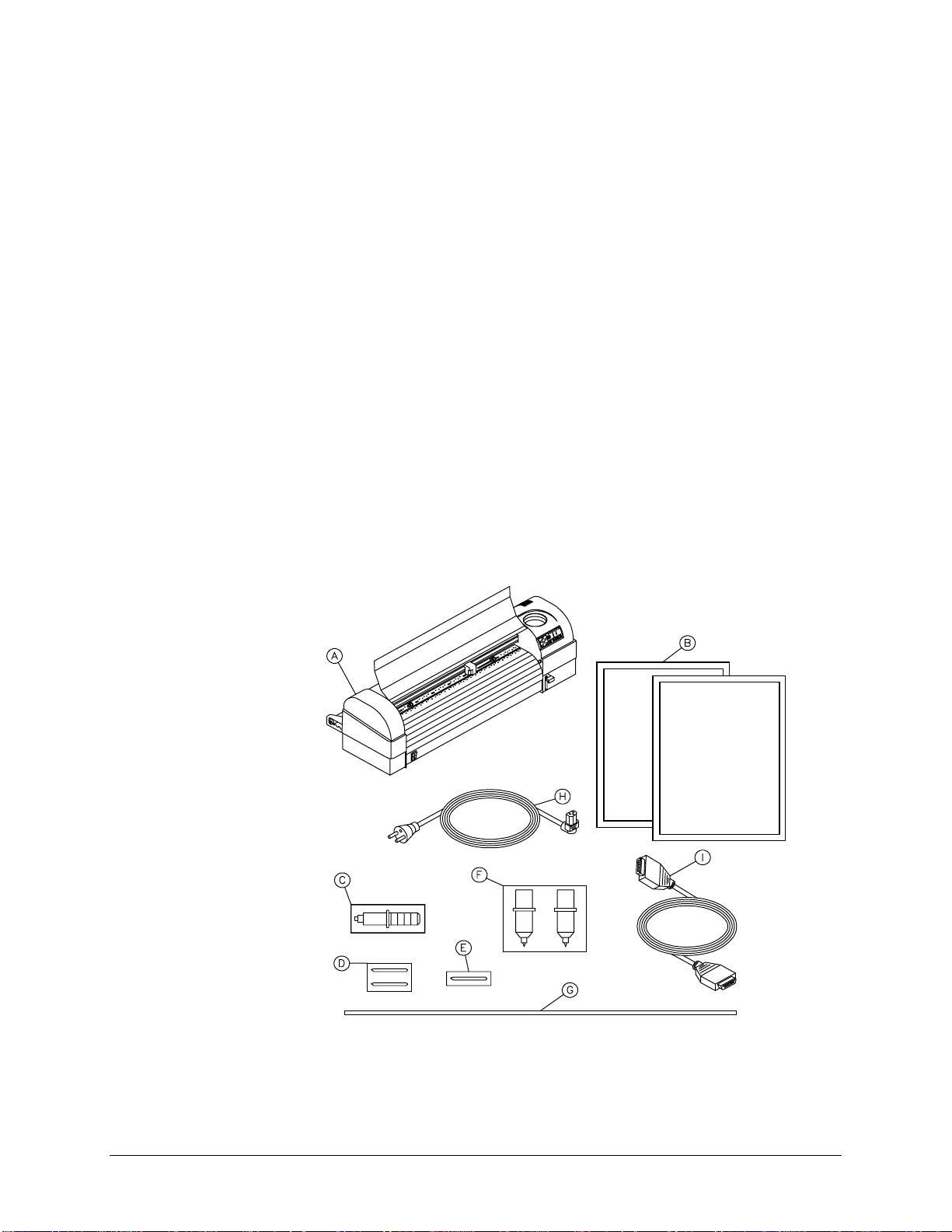
Cutter box contents
A. Cutter unit with roll support system, conveyor rolls, and small flanges.
B. Owner’s Guide and Quick Reference
C. One knife holder
D. Set of 2 blades and 1 spring for cutting jobs (45°/Offset 0.50 mm)
E. Blade for auto-sheet-off (1 pc–installed in tool head)
F. Set of fiber-tip pens (2 pcs)
G. Spare cutting mat (1 pc)
H. Power cord
I. RS-232C serial interface cable
6 Chapter 1, Installation
Page 15
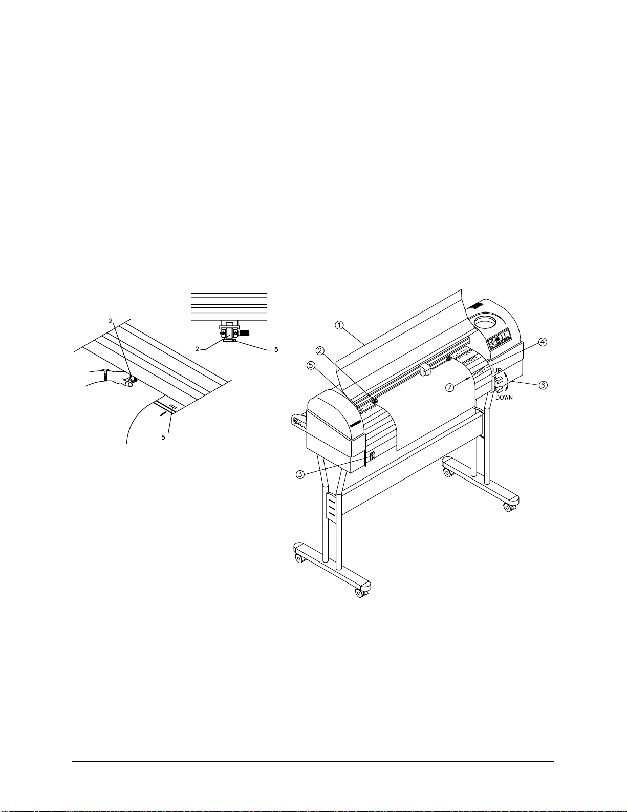
CUTTER PARTS and COMPONENTS
Chapter 1, Installation 7
Page 16

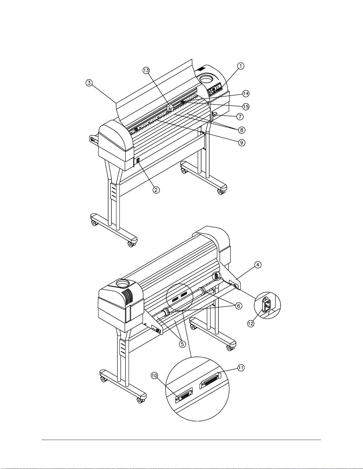
The numbers in the diagram match the parts described below.
1.
Control Panel
2.
Power Switch
3.
Carriage Cover
: Indicator LEDs and control keys.
: Turns the cutter on or off.
: For safety reasons, the cutter will not work with the
cover open. The cover also prevents objects from falling into the
cutting zone.
4.
Roll Support System
5.
Conveyor Rolls
6.
Guiding Flanges
: Carries the conveyor rolls.
: Hold roll material.
: Located on the conveyor rolls, prevent the roll of
material from shifting to the left or right when material is pulled from the
roll.
7.
Material Hold Lever
: Raises and lowers the pressure rollers. Lowering
the pressure rollers holds the material in place.
8.
Platen and Drive Roller Cover
: Supports the cutting material and
guides the movement of the material along the X-axis.
9.
Cutting Mat
: Provides a reliable cutting surface and prevents damage
to the knife tip.
10.
Serial Interface Connector
: RS-232C serial interface connector to
connect the cutter to the host computer.
11.
Parallel Interface Connector
: Centronics parallel connector to
connect the cutter to the host computer's printer port for fast data
transfer.
12.
Power Connector
: Connector for the power cord, which plugs into the
main power supply of the cutter.
13.
Tool head with Tool Mounting Bracket
: All available tools such as
knife holders, drawing pens, and painting pens can be secured into the
tool head using the locking screw. The tool head moves along the Yaxis to the exact cutting position.
14.
Drive Rollers
15.
Pressure Rollers
: Move the cutting material along the X-axis.
: Hold the material against the drive rollers during
cutting.
8 Chapter 1, Installation
Page 17
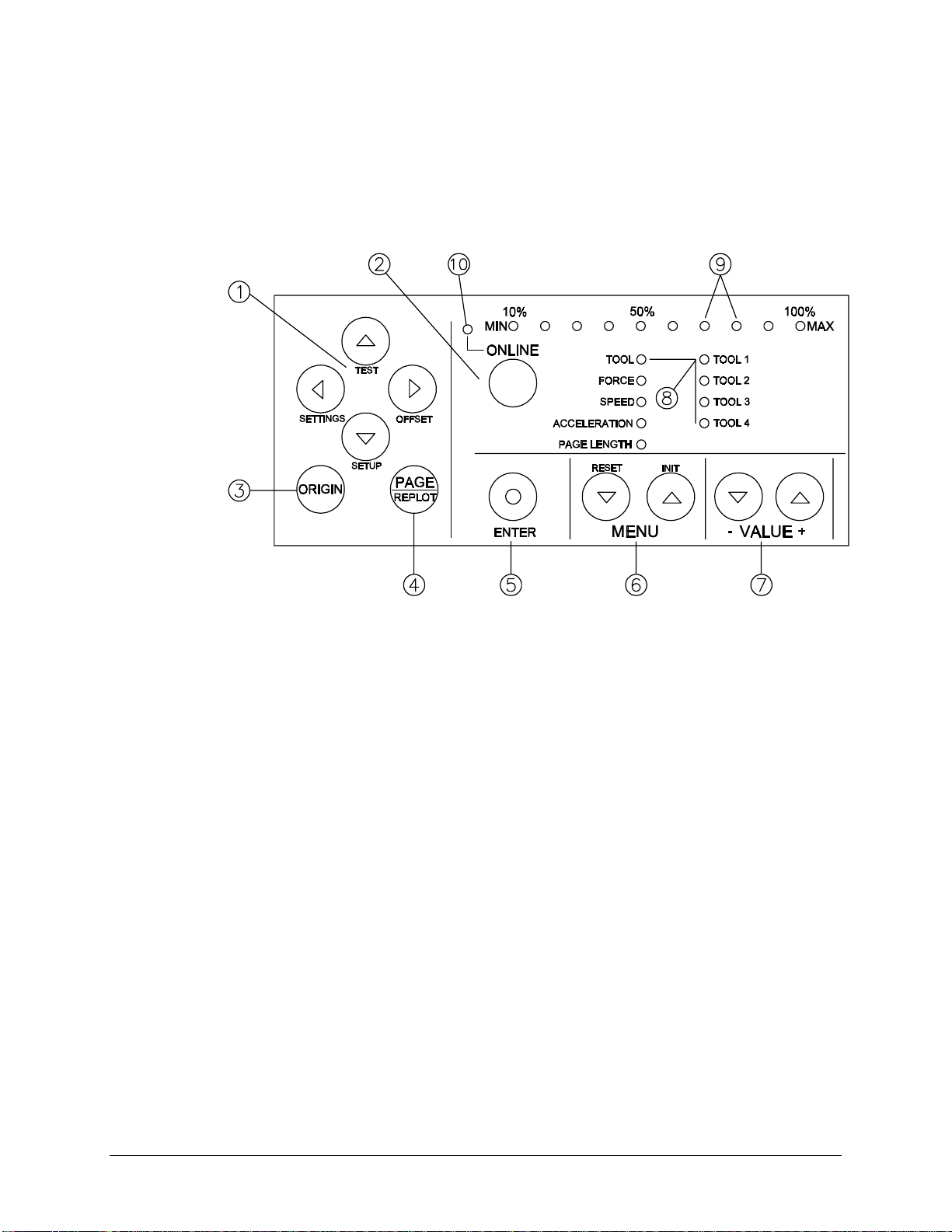
CONTROL PANEL
Use the control panel to access different modes and alter several settings
in order to fine tune the cutter for your needs. The numbers in the diagram
match the keys described below. For detailed information on the functions
of the keys, see
Understanding the Control Panel
on page 18.
1.
Slew:
Manually move the tool head or the material, slew also has
secondary functions when used with enter key.
2.
ONLINE:
3.
ORIGIN:
Switches between online and offli ne modes.
Sets a new origin at the present location of the
tool head.
4.
PAGE:
5.
ENTER:
Performs auto-sheet-off.
■
Gives access to the replot/copy function.
■
Confirms changes and accepts settings.
■
Gives access to special functions indicated by the blue
■
text on the control panel. This is what the blue dot on the
ENTER key signifies.
6.
MENU Selection:
7.
VALUE + and –:
8.
LED indicators:
9.
LED bar:
Indicates values, error messages, and function
confirmation.
10.
ONLINE LED indicator:
Selects the parameter you want to change.
Changes a parameter’s value or setting.
Show cutter parameters and tool selections.
Shows cutter mode (lit when cutter is
online).
Chapter 1, Installation 9
Page 18
Do not use sharp or pointed tools like pens or pencils to press control
panel keys. Press the keys with your fingertips only.
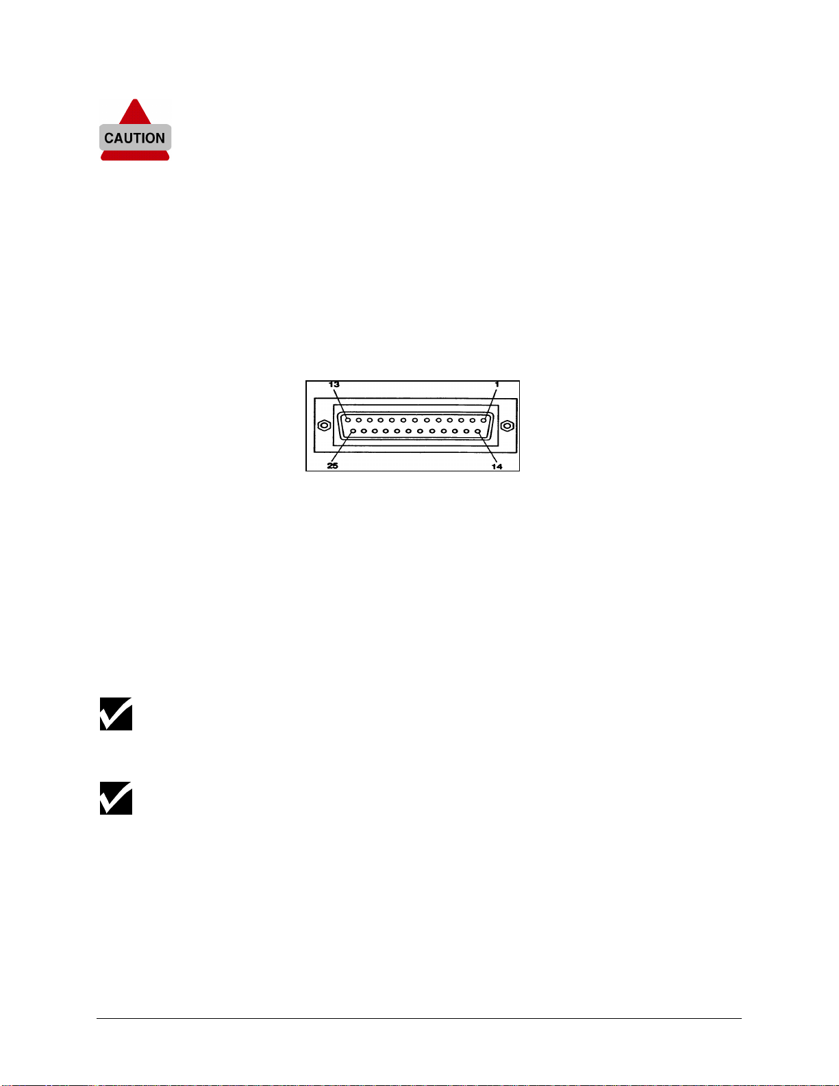
CONNECTING THE CUTTER TO THE COMPUTER
Serial interface
The serial RS-232C interface enables the cutter to be connected to and
controlled by an RS-232C compatible host computer system. The cutter is
equipped with a standard RS-232C - DB-25P connector on the rear panel
and requires a standard RS-232C dB-25S mating connector.
To connect the serial interface
1. Make sure both the cutter and the computer are turned off.
2. Connect one end of the serial interface cable to the serial interface
connector at the back of the cutter.
3. Fasten the screws to secure the connector.
4. Connect the other end of the serial cable to your computer.
For proper operation of the serial communication, it is necessary to match the
computer settings to the cutter settings. For instructions, refer to
Communication Settings, Page 40, in Chapter 3.
Using the serial communication, your cutter will have two-way communication.
It can receive data from the computer and also send information to the
computer, material size, for example.
10 Chapter 1, Installation
Page 19

CONNECTING THE POWER CABLE
1. Make sure the cutter’s power switch is turned off.
2. Plug the cutter end of the power cable into the connector at the back of
the cutter.
3. Plug the other end of the power cable into an electrical outlet of the
correct voltage and with a proper grounding.
The illustration above shows an international AC plug.
Chapter 1, Installation 11
Page 20

INSTALLING KNIFE HOLDERS OR PENS
At the right side of the cutter head, you will find a pivoting mounting
bracket. Opening this bracket will enable you to install a full range of
cutting and drawing tools.
Because you will be performing a test cut with a knife, make sure that you install
a knife with a well-adjusted depth as described in Adjusting the Knife Depth,
page 44 in Chapter 4.
1. Turn the thumbscrew counterclockwise to unlock the tool head
mounting bracket (figure 1).
2. Hold back the clip of the tool head and slide the tool into position,
making sure that the tool collar fits into the groove just beneath the
locking screw (figure 2).
3. Tighten the thumbscrew by turning it clockwise to secure the tool in
position (figure 3).
12 Chapter 1, Installation
Page 21
LOADING MATERIAL
You can load either cut-sheet or roll material. Follow the procedure below
for the type of material you are loading.
To load cut-sheet material
1. Close the protective cover (1).
2. Make sure the pressure rollers (2) are up. If they are not lift them up
using the material hold lever (6 ).
3. Turn on the power switch (3).
The cutter performs its start-up routine and moves the tool head to the
rightmost position.
4. Open the protective cover (1).
5. Insert the material into the cutter, using the two sets of alignment
markers (4) to make sure the right edge of the material is straight.
Position the material so that half of it hangs in front and half of it hangs
in back of the cutter.
6. Adjust the position of the pressure rollers (2) so that they align with the
drive rollers (5). When the left pressure roller is moved into proper
alignment with one of the drive rollers, you will feel and hear it click into
Chapter 1, Installation 13
Page 22

place. The right pressure roller’s movement is limited so that it can
never be positioned incorrectly.
7. Always make sure that all pressure rollers are completely inside the
sheet of material you want to load, so that the rollers do not run on the
very edge of the material. When you use a cut-sheet that does not
have perfectly square corners, it is best to put the pressure rollers at
least ¼" inside the material edge as the width of the sheet may vary.
If you are using a FasTrack 1000 or larger, you have the option of using either
two or three pressure rollers, depending on the width of the material you are
using. When not using the left pressure roller (i.e. when loading material of a
small width), the left pressure roller should be placed at the extreme left of the
cutter (not on top of a drive roller).
The middle pressure roller should always be placed on top of a drive roller.
8. Put the material hold down lever (6) down and close the cover.
The material loading sequence begins, during which the cutter will
measure the loaded sheet. The cutter shuffles the material back and
forth, determining its size and allowing you to ensure that the material
moves easily through the cutter.
Do not try to move the pressure rollers when the material hold lever is
down, as this may damage the system.
After the material loading sequence, the tool head is parked at the
origin position and the cutter is
online
, ready to receive data from the
host computer.
14 Chapter 1, Installation
Page 23
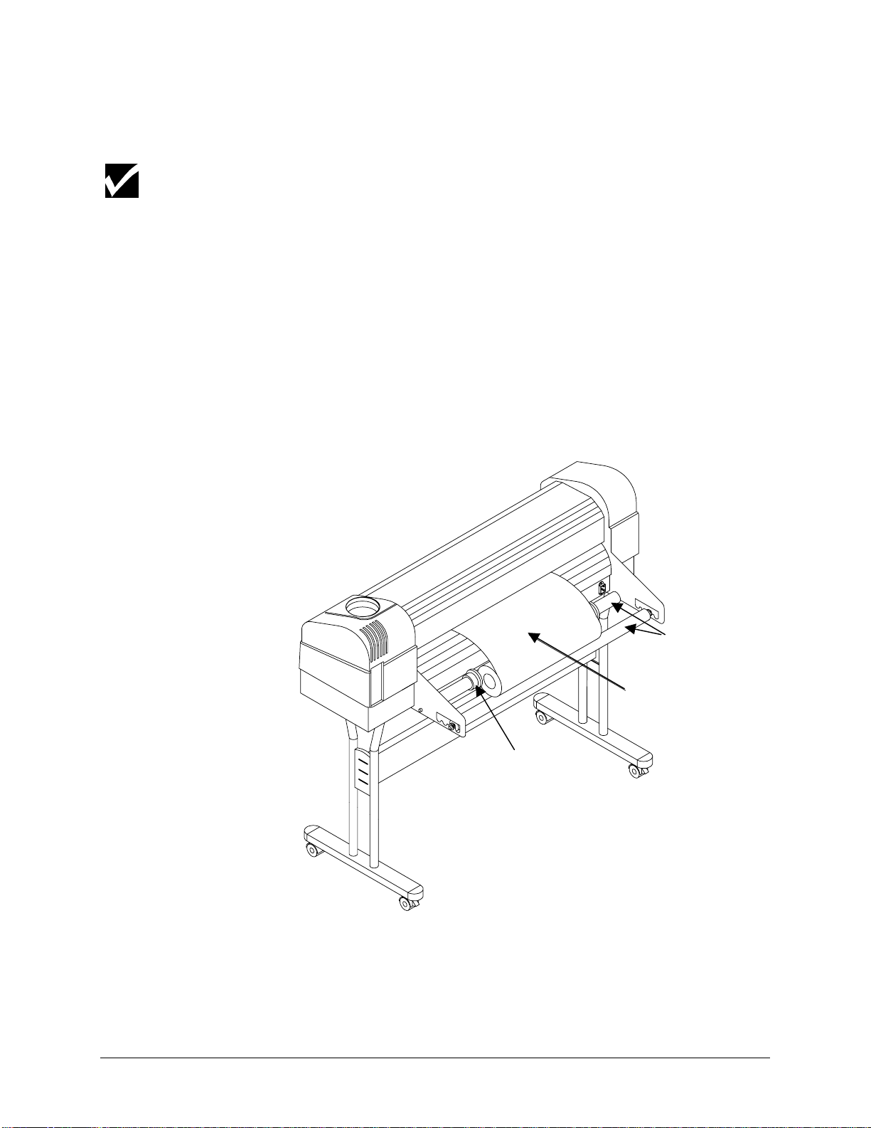
To load roll material
1. Close the protective cover (1).
The numbers in parentheses refer to the numbers on the illustration on page 13.
2. Make sure the pressure rollers (2) are up. If they are not, put them up
using the material hold lever (6 ).
3. Turn on the power switch (3).
The cutter performs its start-up routine and moves the tool head to the
rightmost position.
4. Position the roll of material onto the conveyor rolls. Open the
protective cover, pull the material through, and position the material for
optimal cutting by locating the right edge of the material over the
rightmost drive roller, and the left edge of the material over one of the
other drive rollers.
Conveyor
rolls
Roll
Guiding
flange
5. Adjust the position of the pressure rollers (2) so that they align with the
drive rollers (5) and can accommodate the roll of material. When the
left pressure roller is moved into proper alignment with one of the drive
Chapter 1, Installation 15
Page 24

rollers, you will feel and hear it click into place. The right pressure
roller's movement is limited so that it can never be positioned
incorrectly. Always make sure that both pressure rollers are at least
0.2" (5 mm) inside the edge of the material. Do not let the rollers run on
the very edge of the material.
Do not use the marker lines to align a roll of material! They are for use with cutsheets only! Rolls can only be correctly installed using the EQUAL TENSION
METHOD!
If you are using a FasTrack 1000 or larger, you can use either two or three
pressure rollers, depending on the width of the material used. When not using
the left pressure roller (i.e. when loading material of a small width), the left
pressure roller should be placed at the extreme left of the cutter (not on top of a
drive roller).
The middle pressure roller should always be placed on top of a drive roller.
6. Hold the front edge of the material in the middle with one hand and
with the other hand, the roll itself. As you are holding the roll firmly in
position, pull the front edge of the material forward so that there is an
even tension across the whole width of the roll (= Equal Tension
method.)
The material must be rolled tightly and not telescoped.
7. Adjust the position of the guiding flanges so that they are just
alongside the roll of material, but not directly against it.
8. Close the protective cover.
9. This action starts the material loading sequence, during which the
cutter shuffles a pre-set length of material. The material will be shuffled
back and forth allowing you to make sure the material mov es easil y
through the cutter. The shuffle length is factory-set to 40" (1 m), but
you can adjust the setting if desired. (See
Page Length,
page 27, in
Chapter 2).
10. After the material loading sequence, the tool head is parked at the
origin position and the cutter is
online
, ready to receive data from the
host computer.
16 Chapter 1, Installation
Page 25

To straighten the material edge using the auto-sheet-off utility
The auto-sheet-off mechanism of the cutter can easily cut the front edge
of a new roll of material straight as well as cut off a sheet of material from
a roll, to be used as a separate sheet.
To do this, proceed as follows:
1. Insert the material to be cut (straight) into the cutter as if you were
loading either a roll or a cut sheet, as described above.
2. Make sure the material hold lever is up.
3. Press the PAGE key to request a sheet-off sequence. You will get
visual confirmation of your request by the LED bar, which shows a
flashing sequence of LEDs.
4. Lower the material hold lever and close the cutter’s cover to start the
sequence.
The cutter sheets off the material, producing a neat edge.
The default FORCE used for automatic sheet-off is 300 grams. To adjust this
force, see Force Selection, page 25, in Chapter 2.
Chapter 1, Installation 17
Page 26

CHAPTER 2
CUTTER CONTROLS
UNDERSTANDING THE CONTROL PANEL
The control panel contains 12 keys that perform one or more functions,
such as positioning the tool head, selecting online mode, performing test
cuts, changing settings, and more. All of the keys and their functions are
described in detail below.
There are also 20 LEDs that provide information about the status of the
cutter. Ten of them constitute the LED bar on top of the control panel,
indicating values or showing error messages. All the other LEDs show the
online status of the cutter, which tool selection is in use and which
parameter has been selected.
Online and Offline modes
The ONLINE key is used to switch between the online and the offline
modes of your cutter. Each operating mode allows you to perform a
different set of tasks from the control panel as described below.
When you f i rst switch the cutter on
with no material loaded, the cutter is in offline mode and the
ONLINE LED is off.
with material already loaded, the cutter is automatically in online
mode and the ONLINE LED is lit.
After you load material, the cutter automatically goes online.
18 Chapter 2, Cutter Controls
Page 27

Slew keys
In online mode you can:
Set a new origin
Initiate a sheet-off action
Browse through the parameter settings without changing them
In offline mode, you are in control of the cutter and can alter the cutter
settings such as
Tool Force Speed
Accelerations Page Length Origin
TEST
SETTINGS
ORIGIN key
OFFSET
SETUP
With the slew keys, you can move the tool head and the material so you
can examine specific details of the job or set a new origin (start point). The
slew keys are always active, whether the cutter is online or offline.
When you press the
(left) or ¾ (right) slew key, the tool head moves in
½
the Y-axis, slowly for 2 seconds and then speeds up.
When you press the ¿ (up) or À (down) slew key, the material (if loaded)
moves in the X-axis, slowly for 2 seconds and then speeds up.
The ORIGIN key allows you to register a new origin (start) point if material
has been loaded. A new origin point can be set in offline as well as in
online mode.
To register a new start point
1. Using the slew keys, place the tool head at the desired origin point.
2. Press the ORIGIN key. LEDs on the LED bar will flash to confirm your
action.
If the tool head Is located beyond the borders of the material, the new origin
point will be rejected.
Chapter 2, Cutter Controls 19
Page 28

PAGE key
T
PAGE
REPLO
The PAGE key is available only in online mode. It has two functions:
Function 1:
To perform the Auto-Sheet-Off function. The position
where the auto-sheet-off occurs depends on the situation. If no design
has been cut at the spot where the tool head is parked when pressing
the PAGE key, the cutter will auto-cut at the present location. When a
design has already been cut, the tool head will move to a location 0.2"
(5 mm) beyond the job and will perf orm an auto-cut.
Function 2:
To start the automatic replot/sheet-off function of the last
file that was sent to the cutter—all data that was sent since the last
INITIALIZATION (“IN”) command. Proceed as follows:
1. Press the PAGE key for about two seconds.
On the LED bar, an LED will start blinking. Its position in the bar
indicates the number of copies to be cut. For example, 60% means
6 copies.
2. Using the VALUE +/- keys, select the desired number of copies.
The factory default settings allow a maximum of 10 copies.
3. Press ENTER.
The cutter starts cutting. A new part of the material will be loaded
automatically after every replot.
ENTER key
It is possible to request up to 100 copies by changing the REPLOT
MULTIPLICATION FACTOR in the cutter setup. (See Replot Factor, page 38,
in Chapter 3.
You must press the ENTER key to confirm requested changes to the
cutter settings. A requested change will always be shown by one or more
flashing LEDs for the parameter to be changed. Pressing ENTER will
stop the flashing, indicating that the new setting has been accepted.
The ENTER key also carries a blue dot, indicating it can be pressed
together with another key to access one of the special functions indicated
in blue on the control panel.
20 Chapter 2, Cutter Controls
Page 29

Menu keys
VALUE keys
The MENU selection keys allow you to cycle through the various cutter
parameters to view or change them.
The parameters that can be modified are TOOL, FORCE, SPEED,
ACCELERATION, and PAGE LENGTH. Each is listed on the control panel.
The selected parameter is shown with an LED.
In online mode, pressing the MENU selection keys allows you to verify the
actual settings, though you will not be able to change them
In offline mode, you can select a parameter and then change the value or
the tool selection using the VALUE keys.
Use the VALUE keys to change either settings or parameter values.
To change tools or values:
1. Switch to
offline
mode.
2. Select the parameter you wish to change.
3. Press one of the value keys once to change the parameter.
The LED bar or LED indicating the value or the tool will blink.
4. Press the ENTER key to save the new setting. (Pressing one of the
menu keys again before pressing ENTER will exit without saving the
change.)
Chapter 2, Cutter Controls 21
Page 30

GENERAL PROCEDURE TO CHANGE SETTINGS ON THE CUTTER
1. Make sure you have power to the cutter and that the cutter is in the
offline
If you start with the cutter off (no power),
mode.
and there is no material loaded, the cutter will be in
offline
mode,
which is indicated by the ONLINE LED being off.
and there is material loaded, the cutter will be in
online
mode,
which is indicated by the ONLINE LED being lit. Press the ONLINE
key to take the cutter
offline
, which will be indicated by the ONLINE
LED going out.
If you start with the cutter on (power to the cutter), look at the ONLINE
LED,
if it is lit, press the ONLINE key to put the cutter in the
offline
mode.
The ONLINE LED will go off.
if it is off, the cutter is already in the
offline
mode.
2. Using the MENU keys, select one of the five different parameters
(TOOL, FORCE, SPEED, ACCELERATION, or PAGE LENGTH).
3. Using the VALUE keys, adjust the settings for the selected parameter.
The + key increases the value or selects the next parameter. The - key
decreases the value or selects the previous parameter. A requested
change is indicated by one or several blinking LEDs.
4. Press ENTER to confirm the requested change. (To exit without a
change, press one of the menu keys.)
The blinking stops, indicating that the new setting has been saved.
22 Chapter 2, Cutter Controls
Page 31

TOOL SELECTION
The four tools listed on the control panel are actually four different sets of
tool parameters. For each of the four tools you can register and store
specific values for
TOOLKIND (knife, drawing pen, or pounce)
FORCE
SPEED
ACCELERATION
OFFSET (knives only)
POUNCING GAP (pouncing only).
Switching from tool to tool allows you to switch from one complete setup to
another without having to change any individual value.
Furthermore, to fit your application, you can change the settings in each of
the four setups. This allows you to save the settings for your most popular
material or job types. Then you can swiftly change to a different material
type or application without having to change any of the settings.
(Offset values and correction routines are applied only if a tool is selected
that is defined as a knife. The pouncing gap is only adjustable and active if
a tool is selected that is defined as a pouncing tool.)
There is a fifth tool parameter, TOOL-UP, which is not listed on the control
panel. When tool-up is selected, you can adjust speed and acceleration
for tool-up movements as well as the force used to perform automatic
sheet-off. (The force and acceleration settings included in the four tool
settings are for tool-down movements.)
The procedure below tells you how to choose the tool (setup). The
following sections explain how to change the settings in the setup.
To select which set of tool parameters to use or change
1. Switch the cutter
2. Using the MENU selection keys, select the TOOL option.
The LED next to TOOL must go on.
3. Using the VALUE + or – key , select TOOL 1, TOOL 2, TOOL 3, TOOL
4 or TOOL-UP.
TOOL-UP is selected when all TOOL LEDs are out. The other tools
are indicated by blinking of the associated LED.
4. Press ENTER to confirm your selection or press one of the menu keys
to exit. To access the TOOL-UP status, you also need to press
ENTER, although no flashing LED is visible at that time!
offline
.
Chapter 2, Cutter Controls 23
Page 32

For cutting jobs, use only tools set to KNIFE.
For plotting jobs, use only tools set to PEN.
For pouncing jobs, use only tools set to POUNCE.
When TOOL-UP is selec ted, the FORCE adjustment refers to
the FORCE that will be used for automatic sheet-off.
TOOLKIND SELECTION
Your cutter has 3 different types of tools: knives, drawing pens and a
pouncing (punching) tool. The TOOLKIND selection makes it possible to
change the type of tool that is linked to a specific set of tool parameters
(Tool 1–Tool 4). This is possible using the setup sheet.
The factory default toolkind selection setup is:
TOOL 1 acts as a KNIFE
TOOL 2 acts as a KNIFE
TOOL 3 acts as a PEN
TOOL 4 acts as a PEN
Note that you can always verify the toolkind of the selected tool. When the
tool menu is selected (LED next to Tool is ON), the Led bar on top shows
the current tool type
To change the TOOLKIND
See setup sheet (page 35) Toolkind Selection
Drag Knife
Pen
Pounce
10 20 30%
24 Chapter 2, Cutter Controls
Page 33

FORCE SELECTION
Force is the amount of downward pressure applied by a tool. You are able
to adjust the amount of tool pressure applied by an individual tool so that
you can cut varying thicknesses of material correctly or set the correct
amount of pressure for a pen.
1. Switch the cutter
2. Using the MENU selection keys, select the FORCE option (LED next to
FORCE must be on).
The actual FORCE setting for the selected tool will now be shown on
the LED bar. You can view the value in both offline and online modes.
3. Using the VALUE +/- keys, you can now alter the FORCE settings.
The force is adjustable in three ranges:
15-100 grams, 110-190 grams, and 200-500 grams.
(See explanation on the next page.)
4. Press ENTER to confirm and store, or press one of the menu keys to
exit.
For the procedure to test the force, see Cutting a Test Square To Test Cutting
Pressure (Force), page 49, in Chapter 4.
offline
.
Chapter 2, Cutter Controls 25
Page 34

Force settings are shown by one LED for the first range and combinations
of LEDs for the second and third ranges. Since the actual numbers are not
on the control panel, consult these tables to find the numerical equivalent
of the LEDs shown.
First Range (15 - 100 grams)
Force settings in the first range are indicated by one blinking LED to
indicate the cutting force. The example below shows 80 grams.
15 20 30 40 50 60 70 80 90 100
Second Range (110 - 190 grams)
Force settings are indicated by blinking of the
combination with one of the other LEDs. The example below shows a
setting of 150 grams.
110 120 130 140 150 160 170 180 190
Third Range (200 - 500 grams)
Force settings are indicated by blinking of the
bar in combination with other LEDs in 50-gram increments.
Example showing a 200-gram setting.
200 200 200 200 250 300 350 400 - -
Example showing a 250-gram setting.
200 200 200 200 250 300 350 400 - -
Example showing a 400-gram setting.
LED of the LED bar in
last
first four
LEDs of the LED
200 200 200 200 250 300 350 400 450 500
All available values are shown in the tables at the end of this chapter.
When TOOL-UP is selected, the force adjustment refers to the force
that will be used for the automatic sheet-off.
26 Chapter 2, Cutter Controls
Page 35

SPEED SELECTION
The speed selection allows you to set the tool-down speed, the speed at
which the tool moves through the material.
1. Switch the cutter
2. Using the MENU selection keys, select the SPEED option (LED next to
SPEED must be on).
The current SPEED setting for the selected tool is shown on the LED
bar. You can view the value both offline as and online modes.
3. Use the VALUE +/- keys to change the SPEED setting.
4. Press ENTER to confirm and store, or press one of the menu keys to
exit.
The indicated value only refers to the tool-down speed of the selected tool.
The tool-up speed can be set separately (See Tool Selection page 23, in
this Chapter.
All values being used or available are shown in the tables at the end of
this chapter.
offline
ACCELERATION SELECTION
1. Switch the cutter
2. Using the MENU selection keys, select the ACCELERAT ION opt ion
(LED next to ACCELERATION must be on).
offline
.
.
The current ACCELERATION setting for the selected tool is shown on
the LED bar. You can view the value in both offline and online modes.
3. Use the VALUE +/- keys to change the ACCELERATION settings.
4. Press ENTER to confirm and store, or press one of the menu keys to
exit.
All values being used or available are shown in the tables at the end of
this chapter.
PAGE LENGTH
This parameter is related to loading roll material. The PAGE LENGTH
must be set before a roll is loaded. Set the PAGE LENGTH to a value at
least as large as the job you are going to cut.
Chapter 2, Cutter Controls 27
Page 36

There are three reasons for using a PAGE LENGTH:
The length of material set for the PAGE LENGTH is pulled off the roll
before the cutting job starts, thus preventing material from being pulled
off the roll at high speed and acceleration. High speed movements—
up to 40 ips, (1000 mm/s) and 4.0 G—can be achieved only when the
material can move freely without having to be pulled off the roll during
a job.
Before cutting starts, the complete length of the material is shuffled
back and forth through the cutter, ensuring that the pressure rollers
have a clear path while you have the time to verify that the material
moves easily through the cutter
The Auto-Sheet-Off feature automatically cuts off material at the end of
a cutting sequence. Following an automatic PAGE command or a
manual PAGE command from the control panel, the cutter shuffles
through the pre-set PAGE LENGTH of material to ensure that there is
enough material left for a possible replot. If there is not enough
material left, the cutter will stop before the end of the assigned material
length.
To set the PAGE LENGTH
1. Switch the cutter
offline
.
2. Using the MENU selection keys, select the PAGE LENGTH optio n
(LED next to PAGE LENGTH must be on).
The current PAGE LENGTH setting is shown on the LED bar. You can
view the value in both offline and online modes.
3. Use the VALUE +/- keys to change the PAGE LENGTH settings. Set
the PAGE LENGTH to a value that is at least as large as the sign you
want to cut. The available values for PAGE LENGTH are:
in 0 16 24 32 40 80 120 160 200 400
cm 0 40 60 80 100 200 300 400 500 1000
Each value corresponds with the indications shown on the LED bar.
The default PAGE LENGTH is 40" (1 m).
4. Press ENTER to confirm and store, or press one of the menu keys to
exit.
The use of the PAGE LENGTH should not be regarded as a waste of time. If the
shuffle movement completes without difficulty, the job to be cut will be executed
with very little risk of material tracking problems. In the long run, this saves
time because you won't have to re-cut a complex design because of bad
material alignment.
28 Chapter 2, Cutter Controls
Page 37

The cutting range is not limited by the Page Length that you have set. If a
design that exceeds the shuffle length is sent to the cutter, it will react as
follows:
The first vector that exceeds the limit will be cut using reduced speed for the
distance exceeding the limit.
An additional 8" (20 cm) of material will be pulled from the roll in order to
eliminate any possible snagging at the roll.
After the additional 8" (20 cm) pre-feed, the cutter will continue at the
requested speed until the new limit is exceeded.
These protective measures should not be a reason to avoid changing the page
length, since by not changing it, you will be unable to check the full material
transport before the job is launched.
RESET and CLEAR FUNCTION
In some cases it might be necessary to reset your cutter and/or clear its
buffer while a cutting job is in progress. To do this:
1. Cancel the cutting job in your cutter software so that the data flow is
stopped.
2. Press the ENTER and the MENU down key (RESET) at the same time
for about two seconds.
A sequence of flashing LEDs on the LED bar will indicate that the
cutter has cancelled the current job. The buffer is now empty and the
cutter has stopped cutting.
This reset procedure reinstalls the default original.
Chapter 2, Cutter Controls 29
Page 38

AVAILABLE VALUES/SETTINGS FOR PARAMETERS - IMPERIAL
SYSTEM
All speeds are given in inches per second.
SPEED
TOOL 1
TOOL 2
TOOL 3
TOOL 4
Tool-Up
ACCEL.
TOOL 1
TOOL 2
TOOL 3
TOOL 4
Tool-Up
10% 20% 30% 40% 50% 60% 70% 80% 90% 100%
4 8 12 16 20 24 28 32 36 40
4 8 12 16 20 24 28 32 36 40
24 6 81012 14 16 18 20
4 8 12 16 20 24 28 32 36 40
4 8 12 16 20 24 28 32 36 40
All accelerations are given in G (m/s²).
10% 20% 30% 40% 50% 60% 70% 80% 90% 100%
0.5 1 1.5 2 2.5 3.0 3.5 4 - -
0.5 1 1.5 2 2.5 3.0 3.5 4 - -
0.5 1 1.5 2 2.5 3.0 3.5 4 - -
0.5 1 1.5 2 2.5 3.0 3.5 4 - -
0.5 1 1.5 2 2.5 3.0 3.5 4 - -
All forces are given in grams (1 g = 0.01 Newton)
FORCE
Range 1
Range 2
Range 3
Defaults: TOOL 1 (Knife1) (100 g) TOOL 2 (Knife2) (100 g)
SHUFFLE
Length
Factory Default Settings: TOOL 1 = Knife 1 TOOL 2 = Knife 2
10% 20% 30% 40% 50% 60% 70% 80% 90% 100%
15 20 30 40 50 60 70 80 90 100
110 120 130 140 150 160 170 180 190
200 200 200 200 250 300 350 400 450 500
TOOL 3 (Pen1) (20 g) TOOL 4 (Pen2) (80 g) Sheet-Off (300 g)
All distances are given in inches
10% 20% 30% 40% 50% 60% 70% 80% 90% 100%
0162432
TOOL 3 = Pen 1 TOOL 4 = Pen 2
= Factory default
40 80 120 160 200 400
N/A
30 Chapter 2, Cutter Controls
Page 39

AVAILABLE VALUES/SETTINGS FOR PARAMETERS, METRIC
SYSTEM
All speeds are given in centimeters per second.
SPEED
TOOL 1
TOOL 2
TOOL 3
TOOL 4
Tool-Up
ACCEL.
TOOL 1
TOOL 2
TOOL 3
TOOL 4
Tool-Up
10% 20% 30% 40% 50% 60% 70% 80% 90% 100%
10 20 30 40 50 60 70 80 90 100
10 20 30 40 50 60 70 80 90 100
51015202530 35 40 45 50
10 20 30 40 50 60 70 80 90 100
10 20 30 40 50 60 70 80 90 100
All accelerations are given in G (m/s²).
10% 20% 30% 40% 50% 60% 70% 80% 90% 100%
0.5 1 1.5 2 2.5 3.0 3.5 4 - -
0.5 1 1.5 2 2.5 3.0 3.5 4 - -
0.5 1 1.5 2 2.5 3.0 3.5 4 - -
0.5 1 1.5 2 2.5 3.0 3.5 4 - -
0.5 1 1.5 2 2.5 3.0 3.5 4 - -
All forces are given in grams (1 g = 0.01 Newton)
FORCE
Range 1
Range 2
Range 3
Defaults: TOOL 1 (Knife1) (100 g) TOOL 2 (Knife2) (100 g )
SHUFFLE
Length
Factory Default Settings: TOOL 1 = Knife 1 TOOL 2 = Knife 2,
10% 20% 30% 40% 50% 60% 70% 80% 90% 100%
15 20 30 40 50 60 70 80 90 100
110 120 130 140 150 160 170 180 190 N/A
200 200 200 200 250 300 350 400 450 500
TOOL 3 (Pen1) (20 g) TOOL 4 (Pen2) (80 g) Sheet-Off (300 g)
All distances are given in centimeters
10% 20% 30% 40% 50% 60% 70% 80% 90% 100%
0406080100 200 300 400 500 1000
TOOL 3 = Pen 1 TOOL 4 = Pen 2
= Factory default
Chapter 2, Cutter Controls 31
Page 40

CHAPTER 3
CUTTER SETTINGS and SPECIAL FUNCTIONS
INTRODUCTION
Most of the frequently-used settings are available directly from the
keyboard. However, when setting up the cutter, you must fine tune it to
match the computer setup. Furthermore, the MENU mode operation gives
you access to the setup sheet, allowing you to change special functions
that are not used frequently.
This chapter contains information on how to enter the MENU mode, plot
the setup sheet, and use it to change 32 different settings.
CHANGING THE USER LANGUAGE
It is possible to change the user language of your cutter, thus changing
the setup sheet language. This can be done by pressing two keys
simultaneously during power-up. The combinations are:
LANGUAGE KEY COMBINATION
American (Def ault)
German
French
English
Japanese
MENU MODE OPERATION
1. Install a PEN in the tool head.
2. For optimum plot quality, set the tool selection to a PEN (factory
default TOOL3 and 4).
3. Load a B-size (11" X 17") sheet of paper or larger into the cutter with
the short side on the Y-axis.
4. Switch the cutter to
The ONLINE LED indicator should go off.
offline
ENTER + SLEW DOWN
ENTER + SLEW UP
ENTER + SLEW RIGHT
ENTER + SLEW LEFT
ENTER + ONLINE
by pressing the ONLINE key.
5. Enter the MENU mode by pressing ENTER and slew À (SETUP).
32 Chapter 3, Cutter Settings and Special Functions
Page 41

The cutter now plots a menu selection line (example below).
MENU: xx.xx:
1 2 3 4 5 6 7 8 9 10 11 12 13 14 15 16 17 18 19 20 21 22 23 24 25 26 27 28 29 30 31 32 SHOW
You can now plot a complete setup sheet with all the settings and options
or any of the 32 lines, each showing a single setting and its options. See
the next page for a sample setup sheet.
To plot a complete setup sheet
1. Using the ½ or ¾ (left or right slew) key, park the tool head above the
SHOW function.
2. Press ENTER.
After your selection is plotted, the tool head is returned to the menu
selection line.
To plot a single line and change settings
The column of 32 numbers at the left of the sample setup sheet
correspond to the row of 32 numbers in the menu selection line.
1. Using the ½ or ¾ (left or right slew) key, park the tool head above your
selection in the menu selection line.
2. Press ENTER.
After the line is plotted, the tool head is parked above the current
setting, which is also underlined in the plot.
3. To keep the current setting, use the ¿ or À (up or down) slew key to
return to the menu selection line.
4. To chan ge the setting, use the ½ or ¾ (left or right slew) key to position
the tool head above the desired setting.
5. Press ENTER to save the new setting.
The tool then returns to the menu selection line.
6. To return the cutter to its normal operating mode, put the material hold
lever up and remove the setup sheet from the cutter.
Switching the machine off will not undo any changes that have already been
saved, even if the cutter is still in MENU mode operation when you switch it off.
To reset the cutter to factory defaults, there is a special key code sequence. See
Reset to Factory Defaults, page 43, in this chapter.
When you view a parameter in the setup sheet, the current selection of that
particular parameter is underlined when ENTER is pushed or exit is chosen via
the slew keys.
Chapter 3, Cutter Settings and Special Functions 33
Page 42

Example of a FasTrack Cutter Setup Sheet
p
. Toolkind Tool 1: Knife Pen Pounce
1
2. Toolkind Tool 2: Knife Pen Pounce
3. Toolkind Tool 3: Knife Pen Pounce
4. Toolkind Tool 4: Knife Pen Pounce
5. SheetOff/Pgmode: On/PMO On/PM1 On/PM2 Off/PMO Off/PM Off/PM2
6. Replot factor : x1 x2 x5 x10
7. Smoothing : Off On
8. Communication :
Default 1 Default 2 Default 3 Default 4 Default 5 User Def.
Baudrate: 1200 2400 4800 9600 19200b
9.
10. Data Bits: 7 bits 8 bits
11. Parity: None Odd Even
12. Stop Bits: 1 bit 2 bits
13. Handshake: Off Xon Ack
14. DTR Control: Off On
15. CTS Control: Off On
16. RTS Pin: On Off RTS
17. Command Set: MH-GL2 MC-GL
18. Origin: Center L. Rght L. Lft U. Rght U. Lft
19. Plot Unit: 0.025mm 0.01mm
20. VS, AS, FS: Ignore Accept
s
21. Format: 907 PCI
22. Plot Unit: 0.010mm 0.0125mm 0.025mm
23. SYNC Count: 1 2
24. SYNC Code Hundred: 0 1
25. SYNC Code Ten: 0 1 2 3 4 5 6 7 8 9
26. SYNC Code One: 0 1 2 3 4 5 6 7 8 9
27. Sum Check: No Yes
28. Radix Hundred: 0 1 2
29. Radix Ten: 0 1 2 3 4 5 6 7 8 9
30. Radix One: 0 1 2 3 4 5 6 7 8 9
31. EOB Code Ten: 0 1 2 3
32. EOB Code One: 0 1 2 3 4 5 6 7 8 9
MENU: Firmware Version xx.xx
1 2 3 4 5 6 7 8 9 10 11 12 13 14 15 16 17 18 19 20 21 22 23 24 25 26 27 28 29 30 31 32 SHOW
34 Chapter 3, Cutter Settings and Special Functions
Page 43

GENERAL SETTINGS
The general setting parameters, lines 1 through 7 on the setup sheet,
influence the cutter’s reactions to commands given by the computer or
initiated at the control panel. In the general settings menu, you can set
TOOLKIND, PAGE MODE, REPLOT FACTOR and SMOOTHING. Here's
an example from the setup sheet on the previous page:
1. Toolkind Tool1: Knife Pen Pounce
2. Toolkind Tool2: Knife Pen Pounce
3. Toolkind Tool3: Knife Pen Pounce
4. Toolkind Tool4: Knife Pen Pounce
5. SheetOff/Pgmode: On/PM0 On/PM1 On/PM2 Off/PM0 Off/PM1 Off/PM2
6. Replot Factor: x1 x2 x5 x10
7. Smoothing: Off On
TOOLKIND SELECTION
Lines 1 to 4 of the setup sheet allow you to redefine the toolkind for each
of the four tools. By factory default TOOLS 1 and 2 are defined as knives,
while TOOLS 3 and 4 are defined as pens.
For an explanation of the complete setup for the four tools, which is done
from the control panel, see
Selection, and Acceleration Selection,
To select a TOOLKIND
The example is for Tool 1.
1. Using the ½ and ¾ (left and right slew) keys, position the pen above
selection 1, 2, 3, or 4 in the menu selection line.
2. Press ENTER to confirm this choice.
The cutter plots the following line
1. Toolkind Tool1: Knife Pen Pounce
after which the tool head parks above the current setting.
3. To keep the current setting, use the ¿ and À (up and down) slew keys
to return to the menu selection line.
4. To chan ge the setting, use the ½ and ¾ (left and right slew) keys to
position the tool head above the desired setting.
5. Press the ENTER key to save the new setting into memory.
At the same time, the tool head returns to the menu selection line,
allowing a new selection.
Tool Selection, Force Selection, Speed
starting on page 23, in Chapter 2.
Chapter 3, Cutter Settings and Special Functions 35
Page 44

SHEET-OFF / PAGE MODE
This is a combination of two parameters: sheet-off and page mode. You
can select any one of three page modes with the auto sheet-off feature
turned on or off.
With the auto-sheet-off part, you can enable or disable the automatic
sheet-off facility. When the auto-sheet-off function is disabled, no
sheeting off will occur.
The page mode part determines the cutter’s reaction to a PAGE
command as sent by the cutting software. The PAGE command is
used to relocate the origin after a job is finished and can take control
remotely of the cutter’s automatic sheet-off feature. Sheeting-off
automatically, without user intervention, is a unique feature of
FasTrack cutters that enhances the cutter’s versatility and overall
performance enormously.
Page commands
A PAGE command is sent to the cutter by the host computer software as
either a “PG;”, or “Pgn;”, where “n” is a number in millimeters.
If the PAGE command “PG;” is sent, the cutter will automatically sheet off
regardless of the Page Mode, minimizing the loss of material.
If the PAGE command “Pgn;” is sent, the number after the PG command
will be interpreted differently, depending on the page mode you have
chosen:
Page Mode 0 (PM0): The number after the PAGE command is ignored.
The material will be cut 0.2" (0.5 cm) after the furthest vector and the
new cutting limit will be located 0.2" (0.5 cm) from the lower material
border.
Page Mode 1 (PM1): The new origin is located “n” millimeters beyond
the last vector that was sent.
Page Mode 2 (PM2) = default: The new origin is located “n” millimeters
beyond the previous origin position.
Refer to the manual for your software to find out what kind of page mode your
software sends to the cutter.
36 Chapter 3, Cutter Settings and Special Functions
Page 45

: Original origin.
A
: End point last vector
B
: New origin with
C
: New origin with
D
To set the SHEET-OFF / PAGE MODE
1. Using the ½ and ¾ (left and right slew) keys, position the pen above
selection 5 in the menu selection line.
2. Press ENTER to confirm this choice.
The cutter will plot the following line:
5 SheetOff / PGmode: PM0 PM1 PM2
after which the tool head will park above the current setting. The
factory default is Page Mode 2.
Page Mode 1
Page Mode 2
3. To keep the current setting, use the ¿ and À (up and down) slew keys
to return to the menu selection line leaving the original setting
unchanged.
4. To chan ge the setting, use the ½ and ¾ (left and right slew) keys to
position the tool head above the desired setting.
5. Press the ENTER key to save the new setting into memory.
At the same time, the new selection is underlined and the tool head
returns to the menu selection line, allowing a new selection.
Chapter 3, Cutter Settings and Special Functions 37
Page 46

REPLOT FACTOR
If you want to make multiple copies of a design, the easiest way is to send
the job from your computer. However, you can also use the replot factor in
the cutter. Using the replot factor, it is possible to request more than 10
copies when the automatic replot utility is used. The replot factor indicates
the multiplication factor (2,5, or 10) that the cutter will use to determine
how many copies are requested.
EXAMPLE: If the replot factor is (times) 5 and the third LED is selected to
indicate the number of copies, a total of 15 copies will be generated.
To set the replot factor
1. Using the ½ and ¾ (left and right slew) keys, position the pen above
selection 6 in the menu selection line.
2. Press ENTER to confirm this choice.
The cutter will plot line 6.
6) Replot Factor: x1 x2 x5 x10
after which the tool head will park above the current setting. The
factory default is times 1.
3. To keep the current setting, use the ¿ and À (up and down) slew keys
to return to the menu selection line leaving the original setting
unchanged.
4. To chan ge the setting, use the ½ and ¾ (left and right slew) keys to
position the tool head above the desired setting.
5. Press the ENTER key to save the new setting into memory.
At the same time, the new selection is underlined and the tool head
returns to the menu selection line.
38 Chapter 3, Cutter Settings and Special Functions
Page 47

SMOOTHING
Smoothing rounds sharp corners. It can be set on or off. Depending on
your choice, the cutter cuts obtuse angles differently.
If the complementary angle (n) between two consecutive vectors A and B
is larger than the smoothing angle, the cutter will slow down and cut a
sharp corner (1). If the angle is smaller, the cutter will maintain its speed
and cut a rounded corner (2). The optimum smoothing angle is calculated
internally.
When smoothin g is turned off, all corners will be cut sharply. The time
difference between cutting a job with smoothing on and cutting it with
smoothing off is negligible.
To change the smoothing settings
1. Using the ½ and ¾ (left and right slew) keys, position the pen above
selection 7 in the menu selection line.
2. Press ENTER to confirm this choice.
The cutter plots line 7:
7) SMOOTHING: Off On
after which the tool head parks above the current setting. The factory
default is on.
3. To keep the current setting, use the ¿ and À (up and down) slew keys
to return to the menu selection line.
4. To chan ge the setting, use the ½ and ¾ (left and right slew) keys to
position the tool head above the desired setting.
5. Press the ENTER key to save the new setting into memory.
At the same time the new selection is underlined and the tool head
returns to the menu selection line, allowing a new selection.
Chapter 3, Cutter Settings and Special Functions 39
Page 48

COMMUNICATI O N SETTINGS
For your cutter to communicate with your host computer, the
communication settings on both machines must match exactly. In the
Setup sheet, they can be found in lines 8 to 16:
8 Communication: Default 1 Default 2 Default 3 Default 4 Default 5 User Def
9 Baudrate: 1200 2400 4800 9600
10 Data Bits: 7 bits 8 bits
11 Parity: None Odd Even
12 Stop Bits: 1 bit 2 bits
13 Handshake: Off Xon ACK
14 DTR Control: Off On
15 CTS Control: Off On
16 RTS Pin: On Off RTS
In the factory, several commonly used sets for items 9 through 16 have
been preinstalled. (See below.) Refer to your software manual to
determine if you can use the default setting (in which case you don't have
to make any changes), use one of the other preinstalled sets, or need to
make changes to some of the items in lines 9 through 16.
19200 bps
Menu selection options 9 to16 are only available if the parameter User Defined
is selected in line 8. If you use one of the default settings, all other
communication parameters are automatically set.
Factory default
DEFAULT1DEFAULT2DEFAULT3DEFAULT4DEFAULT
5
BAUDRATE 9600 9600 9600 9600 9600
DATABITS 7 8788
PARITY EVEN NONE EVEN NONE EVEN
STOPBITS 1 1 112
HANDSHAKE OFF OFF X-ON X-ON OFF
DTR ON ON OFF OFF ON
CTS OFF OFF OFF OFF OFF
RTS ON ON ON ON ON
40 Chapter 3, Cutter Settings and Special Functions
Page 49

To change the serial communication settings
In line 8, choose one of the preinstalled sets or the User Defined selection.
If you need to use the User Defined option, alter the settings one by one
until they match the desired values.
6. Using the ½ and ¾ (left and right) slew keys, position the tool head
above the desired selection (between 8 and 16) in the menu selection
line.
7. Press ENTER to confirm this choice.
The cutter plots the corresponding line and the tool head parks above
the current setting. The factory default setting is default 2.
8. To keep the current setting, use the ¿ and À (up and down) slew keys
to return to the menu selection line leaving the original setting
unchanged.
9. To chan ge the setting, use the ½ and ¾ (left and right slew) keys to
position the tool head above the desired setting.
10. Press the ENTER key to save the new setting into memory.
At the same time, the new selection is underlined and the tool head
returns to the menu selection line, allowing a new selection.
Chapter 3, Cutter Settings and Special Functions 41
Page 50

LANGUAGE SETTINGS
Your cutter can understand two different graphic languages, MH-GL/2
(HPGL™/2 - compatible) and MC-GL (Ca lcomp Compatible). So that you
can fully use them, settings for them are available in the cutter setup
mode. In the setup sheet, the language settings are in lines 17 to 32.
17) Command Set: MH-GL/2 MC-GL
18 Origin: Center L. Right
19 Plot Unit: 0.025mm 0.010mm
20 VS-AS-FS: Ignore Accept
21 Format: 907 PCI
22 Plot Unit: 0.010mm 0.0125mm 0.025mm
23 SYNC Count: 1 2
24 SYNC Code
Hundred:
25 SYNC Code Ten: 0 1 2 34 56 7 89
26 SYNC Code One: 0 1 2 34 56 7 89
27 Sum Check: No Yes
28 Radix Hundred: 0 12
29 Radix Ten: 0 1 2 3 4 5 6 789
30 Radix One: 0 1 2 3 4 56789
31 EOB Code Ten: 0 1 23
32 EOB Code One: 0 1 2 3 4 56789
0 1
L. Left U. Right U. Left
When MH-GL/2 is activated in menu option 17, the menu options 21-32 will
NOT be available.
When MC-GL is activated in menu option 17, menu-options 18-20 will NOT be
available.
The first choice to make is the language type: MH-GL/2 or MC-GL. The
factory default is MH-GL/2.
When using MH-GL/2, three setti ngs are available:
1. Origin: Center, Lower Right, Lower Left, Upper Right and Upper Left.
Lower Right is factory default.
2. Plot Unit: 0.025 mm or 0.01 mm. Factory default is 0.010mm. If these
values are not set correctly, all your jobs will be too large or too small.
3. VS-AS-FS: Several cutting software packages enable your to send
SPEED, ACCELERATION and FORCE commands to the cutter from
42 Chapter 3, Cutter Settings and Special Functions
Page 51

the software. The cutter can be set up to ACCEPT or IGNORE these
commands.
When using MC-G L, twelve se ttings are available. Please refer to your
software manual to look for the necessary values if this language is
needed.
To change language settings
1. Using the ½ and ¾ (left and right slew) keys, position the pen above
one of the selections 17 to 32 in the menu selection line.
2. Press ENTER to confirm this choice.
The cutter plots the corresponding line and the tool head parks above
the current setting.
3. To keep the current setting, use the ¿ and À (up and down slew) keys
to return to the menu selection line.
4. To chan ge the setting, use the ½ and ¾ (left and right slew) keys to
position the tool head above the desired setting.
5. Press the ENTER key to save the new setting into memory.
At the same time, the new selection is underlined and the tool head
returns to the menu selection line, allowing a new selection.
RESET TO FACTORY DEFAULTS
If it is necessary to reset your cutter to its factory default settings, switch
the cutter on while pressing the ORIGIN and the PAGE keys at the same
time.
The LED bar confirms this action. The LEDs display a running light from
the outside to the inside several times.
Using this function will fully re-initialize your unit. All previously stored
language and communication settings will be reset.
In case of doubt, first plot out a setup sheet using the show option of the menu
selection line.
It is also possible to set the factory default settings when in "STANDALONE
MODE" by pressing the ENTER + MENU up keys. An LED sequence confirms
the settings to factory default. This procedure is equivalent to pressing the
ORIGIN and PAGE keys during startup.
Chapter 3, Cutter Settings and Special Functions 43
Page 52

CHAPTER 4
FINE TUNING THE CUTTER
The FasTrack cutter provides a step-by-step method to help beginning
users achieve excellent cutting quality. Once you have more experience
with your cutter, you will be able to fine tune your cutter quickly and
accurately.
There are several knife types available, each designed for cutting specific
material.
Cutting Blade 1 Cutting Blade 2 Cutting Blade 3
Top Angle 45º 30º 60º
Typical Offset 0.50 mm 0.50 mm 0.50 mm
Default Speed 50 cm/s (20"/s) 50 cm/s (20"/s) 50 cm/s (20"/s)
Default Force 100 g 100 g 100 g
Default
3.0 G 3.0 G 3.0 G
Acceleration
There are three factors to consider when setting up your cutter for a
demanding cutting job:
The knife depth
The cutting pressure
The offset
This section covers
Adjusting the knife depth
Setting the cutting pressure
Adjusting the offset
Performing a test cut
44 Chapter 4, Fine Tuning the Cutter
Page 53

ADJUSTING THE KNIFE DEPTH
Two types of high quality knife holders are available for FasTrack cutters,
a standard knife holder, and an optional kn ife holder with a vernier to
adjust the depth.
Regardless of which type of knife holder you use, adjusting the knife depth
is very important to ensure high quality outputs. Always make sure that the
knife blade protrudes from the holder enough to cut through the material
and adhesive, but not the backing.
Material
Knife
Holder
Blade
Backing
To adjust the knife depth of the standard tool holder
1. Hold the body in one hand and adjust the depth by using the set screw.
Turning the set screw clockwise will make the blade protrude out of the
edge of the base. Turning the set screw counterclockwise will retract
the blade.
Base
Body Set S crew
2. For a first test, turn out the blade until it protrudes only a very small
amount (about 0.008" (0.2mm) out of the base.)
Chapter 4, Fine Tuning the Cutter 45
Page 54

3. Make a manual test cut on a small piece of material of the same type
that you will be using.
4. Examine the test cut.
The top layer should be cut completely and you should be able to see
a slight scratch on the backing when peeling it off, but no scratches
from the underside of the backing.
5. Adjust the blade and make manual test cuts until you obtain the correct
depth.
Excessive blade exposure will adversely affect cutting quality, accelerate
blade wear, and possibly damage the cutter.
46 Chapter 4, Fine Tuning the Cutter
Page 55

To adjust the knife depth of the optional knife holder
1. Loosen the base of the cutting knife. To do this, take the base in your
left hand and twist the ring slightly.
2. Take the base and the ring in your left hand and twist the shaft until the
knife point protrudes only a very small amount, about 0.008" (0.2 mm)
out of the edge of the base.
3. Tighten the ring firmly against the base. This will prevent the cutting
blade from coming loose during cutting.
4. Make a manual test-cut on a small piece of material of the same type
that you will be using.
5. Examine the test cut.
The top layer should be cut completely and you should see a slight
scratch on the backing when peeling it off, but not on the underside of
the backing.
6. Adjust the blade depth and make test cuts until you obtain the correct
depth.
Excessive blade exposure will adversely affect cutting quality, accelerate
blade wear, and possibly damage the cutter.
Chapter 4, Fine Tuning the Cutter 47
Page 56

FEATURES OF THE OPTIONAL KNIFEHOLDER
For some applications more precise adjustment in the depth of the knife
blade is helpful. For those applications, Gerber can provide you with an
optional knife holder featuring a vernier that allows you to adjust the depth
of the knife in increments of 0.0004" (0.01 millimeter). For more
information on the optional knife holder, please contact your Gerber
distributor.
The upper scale lines make it possible to change the knife depth over
0.002" (0.05 mm).
The lower scale (vernier) makes it possible to change the knife depth
over 0.0004" (0.01 mm).
48 Chapter 4, Fine Tuning the Cutter
Page 57

SETTING THE CUTTING PRESSURE / TEST SQUARES
You are cutting a test square to see if you need to adjust the cutting
pressure as described in
should cut your design with the lowest possible pressure that permits easy
weeding. Some cast material requires only 15 grams to be cut completely
through. In that case there is no need to apply 100 grams of pressure. Too
much pressure can cause a decrease of quality, premature blade wear,
and may damage the cutter.
You can cut a small test square using the current force settings as follows:
Force Selection,
page 25, in Chapter 2. You
1. Make sure the cutter is
2. Select the FORCE menu by pressing MENU ¿/À keys until the
FORCE LED is on.
3. Using the slew keys, select the position where you want to cut the test
square.
4. Press the ENTER key for about two seconds.
The cutter will cut a test square.
SETTING THE OFFSET
One of the most important factors to obtain good cutting quality is the
offset. The knife offset is the distance between the knife center and the
knife tip. Because accurate measurement off the offset is very difficult, you
should adjust the offset by checking cutting results on the material to be
used. Your FasTrack cutter provides an offset adjustment feature to help
you set an accurate offset.
offline
. Online LED should be off.
Chapter 4, Fine Tuning the Cutter 49
Page 58

The diagrams below illustrate the results of incorrectly measured offsets.
Pointed corners: The offset is larger
than the actual knife offset.
In this case, a square corner will look like
the example to the right.
The cutting direction is indicated by the
arrow. The corners are not well formed
because the cutter cuts too far beyond the
corner.
Rounded corners: The Offset is smaller
than the actual knife offset.
In this case, a square corner will look like
the example to the right.
The cutting direction is indicated by the
arrow. The corners are not well formed
because the cutter did not cut far enough
before turning the corner.
ADJUSTING THE OFFSET
To obtain good quality, you should perform this routine each time you
change cutting blades or switch to another type of material.
1. Make sure the cutter is switched on.
2. Load a sheet of material about 10" (25 cm) wide.
3. Select a tool that is defined as a KNIFE (factory default: TOOL 1 is
Knife 1, TOOL 2 is Knife 2).
If you select a TOOL that is defined as a PEN (factory default: TOOL 3
is Pen 1, TOOL 4 is Pen 2), the cutter will not react, as this function is
only active for knife settings.
4. Switch the cutter
LED indicator should then go off.
5. Press the ENTER and OFFSET (➢) keys simultaneously. This will put
the cutter into the OFFSET test mode.
offline
by pressing the ONLINE key. The ONLINE
50 Chapter 4, Fine Tuning the Cutter
Page 59

The flashing LED on the LED bar now shows the BASE OFFSET
VALUE. Depending on the LED which is flashing, the base value can
range from 0.004" (0.1 mm) to 0.04" (1 mm) as shown below.
0.1mm 0.2mm 0.3mm 0.4mm 0.5mm 0.6mm 0.7mm 0.8mm 0.9mm 1mm
6. Using the VALUE +/- keys, adjust the base value to match the offset
value of the blade installed in your knife holder. The base offset value
is indicated on the box in which the blades are packed. For the blades
that come with the cutter, this value is 0.02" (0.5 mm).
7. Press ENTER to confirm the BASE OFFSET value.
The cutter will now be
offline
, indicated by the ONLINE LED indicator
not lit. This gives you the opportunity to adjust any settings necessary
(SPEED, ACCELERATION, FORCE).
8. Press the ONLINE key to switch the cutter
online
.
The cutter will now generate a set of test patterns, each of them with a
different offset.
If the base offset is set to 0.02" (0.5 mm), the generated offsets will
vary from 0.018" (0.46 mm) up to 0.022 " (0.55 mm) . When the test cuts
are completed, the cutter will advance the ma terial.
9. Check the patterns and determine which of them gives best quality.
Look for optimum quality of the corners, closure of the circles, and
easy weeding.
After the machine has drawn the 10 squares to select the best offset,
the head is no longer positioned above the most left one. It is now
positioned above the square belonging to the base offset.
10. You can now use the test cut squares the same way you use the menu
selection line to select and enter your choice for blade offset. Using the
and ¾ (left and right slew) keys, move the tool head to the square
½
with the best quality. You will see an LED on the LED bar move
according to your choice. When the tool head is moved, the material is
partially retracted, but in such a way that the test squares remain
visible.
11. Press ENTER to confirm your choice.
The cutter is now in LOCAL mode.
12. If needed, you can now restart the offset adjustment routine to
experiment with a different force, speed and/or acceleration. (Step 5)
Chapter 4, Fine Tuning the Cutter 51
Page 60

13. When you are satisfied with the new setting, set the cutter
pressing the ONLINE key. The ONLINE LED should then come on.
14. Press PAGE to sheet-off the test squares.
If you have 2 knife holders available, you can adjust each one for a different
type of material and save the settings as KNIFE 1 and KNIFE 2. This will allow
you to switch quickly from one material or job type to the other.
An inaccurate offset setting may cause poor cutting quality and difficult
weeding.
If the offset adjustment routine is aborted, the cutter will continue working with
the value it had prior to starting the adjustment routine.
SETTING UP FOR POUNCING (PUNCHING) APPLICATIONS
Your FasTrack cutter can very easily be set up to perform pouncing
applications.
For optimum quality, Gerber recommends using the optionally available soft
cutting mat for pouncing applications. This cutting mat allows a better
penetration of the pyramid-shaped pouncing pin.
online
by
To perform a pouncing job use one of the following two methods:
Method 1. Pen-Up / Pen-Down sent by cutting software
1. Set the tool settings to a PEN.
2. Set the FORCE to produce acceptable results within the range of 15 to
500 grams.
Method 2. Use the incorporated pouncing (punching) capability of the cutter
1. In the cutter set up, set the TOOLKIND of the tool of your choice to
POUNCE
2. Press ENTER and ➢ (slew right).
3. Select the desired gap (distance between punch marks) using the
VALUE + /- keys.
10% 20% 30% 40% 50% 60% 70% 80% 90% 100%
1 mm 2 mm 3 mm 4 mm 5 mm 6 mm 7 mm 8 mm 9 mm 10 mm
4. Press ENTER to confirm your choice.
5. The FORCE can be varied in the range of 15 - 500 grams.
52 Chapter 4, Fine Tuning the Cutter
Page 61

The factory defaults are:
1) Toolkind Tool1: Knife Pen Pounce
2) Toolkind Tool2: Knife Pen Pounce
3) Toolkind Tool3: Knife Pen Pounce
4) Toolkind Tool4: Knife Pen Pounce
For more details refer to Toolkind Selection, page 24 in Chapter 2 and page 35
in Chapter 3.
To adjust the pouncing tool
1. Turn the positioning screw until the pouncing tool is about to protrude
from the holder.
2. Turn back the positioning screw one full turn. The punching pin will
then be about .039" (1 mm) inside the holder.
Chapter 4, Fine Tuning the Cutter 53
Page 62

PERFORMING A TEST CUT
To check if the cutter is fully functional, there is an integrated
demonstration test cut routine, which can be done without using a
computer. To perform this demo cut:
1. Load some material (cut-sheet or roll) into the cutter.
2. Set TOOLKIND to KNIFE 1 or KNIFE 2, if not already set.
3. Make sure that a knife with well adjusted depth is mounted into the tool
head.
4. If you have not yet adjusted the offset for the current knife and/or
material, do so now to obtain perfect quality. (See
page 50, in this chapter).
Adjusting the Offset,
5. Switch the cutter
LED should go off.
6. Start the test-cut by pressing ENTER and ¿ (up) slew simultaneously.
The test cut is not scaled automatically to fit the material size. In case
of a roll of material, only the width of the roll is taken into account. The
cutter assumes that there is enough material on the roll to perform a
full- width test cut. You can determine the size of the test cut by
adjusting the position of the pressure rolls.
offline
by pressing the ONLINE key. The ONLINE
54 Chapter 4, Fine Tuning the Cutter
Page 63

GENERATING A PARAMETER SETTINGS PLOT
1. You can plot out all of your cutter’s internal information (machine type,
EPROM and EEPROM versions) as well as all the user definable
settings, such as tool speeds, acceleration, forces, offset values, etc.
This information is useful if you need to contact your Gerber distributor
or technical support
2. Load a sheet of B-size (11" X 17") paper or larger into the cutter.
3. Set the tool selection to pen for optimum plot quality. By factory
default, TOOL 3 and TOOL 4 are defined as being PENS.
4. Mount a pen in the tool head.
5. Switch the cutter
offline
by pressing the ONLINE key. The ONLINE
LED should then go off.
6. Start the plot by pressing ENTER and ½ (left slew) simultaneously.
The cutter plots a display similar to the one below.
FasTrack Settings Plot
Machine : FasTrack-650
Version EPROM :
XX.XX
EEPROM :
XX.XX
Tool : Tool1 Tool2 Tool3 Tool4 Pen-Up
Force (g) : 100 100 20 80 --Speed (in/s) : 24 24 16 24 39
Acceleration (G) : 2.5 2.5 4.0 4.0 4.0
Page Length : 40 in
Toolkind Tool1 : Knife 0.021 in
Tool2 : Knife 0.021 in
Tool3 : Pen
Tool4 : Pen
User Language : American
Chapter 4, Fine Tuning the Cutter 55
Page 64

CHAPTER 5
CUTTER MAINTENANCE and TROUBLESHOOTING
In this chapter, you will learn:
How to keep your cutter in good shape and prevent problems by
regularly performing some easy, daily maintenance.
How to pinpoint and correct problems that might occur.
CLEANING and DAILY MAINTENANCE
Your cutter, knives, and pens will work better and last longer if you keep
them clean and perform a few simple daily maintenance tasks.
To clean the pressure rollers and drive rollers
The figure below shows you this part of the cutter that might require your
attention.
Pressure rollers
Always leave the pressure rollers in the up position when they are not in use.
Make it a habit to clean the pressure rollers regularly with an alcohol-
moistened swab or rag to keep them smooth and level.
Drive rollers
The pressure rollers (2) press the material firmly against the friction drive
rolls (5), which have a gritty surface that enables them to grip the back of
the material and drive it through the cutter. Because of this, the friction
drive rolls (5) can become clogged with residue from cutting material. This
56 Chapter 5, Cutter Maintenance and Troubleshooting
Page 65

can cause the material to slip, resulting in inaccurate cuts or incorrect
material transport.
For a light cleaning, brush them with a soft-bristle brush, such as a
paintbrush or toothbrush. While brushing, rotate the rollers manually to
make sure they are clear of paper dust and thoroughly clean.
For a more thorough cleaning, run an 18" long piece of 1½ " masking
tape between each drive roller and a pressure roller (in the down
position) with the adhesive side towards the drive roller.
To remove material particles from the cutter blade in a standard knife holder
Use following procedure to remove small material particles in the base of
the cutting blade holder.
1. Take the body (2) into one hand and unscrew the base (1).
2. Blow away the material particles accumulated in the top of the base.
3. Remove the spring from the cutting blade and remove any residual
material from the blade tip.
4. Place the spring back over the cutting blade and tightly screw the base
on the holder.
To remove material particles from the cutter blade in an optional knife holder with
vernier
1. Take the ring in your hand and remove the base.
2. Blow away the material particles accumulated in the top of the base.
3. Remove any residual material from the blade tip.
Chapter 5, Cutter Maintenance and Troubleshooting 57
Page 66

4. Place the base back on the holder and twist it tightly.
To clean the cutter
Use a soft cloth to clean paper dust and particles off the platen, the
drive roller cover, the cutting mat, the Y-axis rail, and the protective
cover. (See
part identification.)
Use a cotton swab to clean the two round material sensors located on
either side of the cutting mat near the right end of the platen. You may
moisten the swab with alcohol if necessary.
Make sure there is no material or other material stuck to the material
transport areas.
PARTS REPLACEMENT
Although the cutter has been constructed of high quality materials, in order
to maintain high quality output, you will periodica lly ha ve to replace some
parts that are subject to wear and tear.
Cutter Parts and Components,
page 7, in Chapter 1 for
To replace the cutting mat
1. Remove the worn cutting mat by pulling it out, together with the
underlying strip of vinyl.
58 Chapter 5, Cutter Maintenance and Troubleshooting
Page 67

2. Cut a strip of vinyl 0.3" (8 mm) wide and its length depending on the
size of your cutter. Stick this strip into the cutting groove.
3. Complete this procedure by sticking the new cutting mat into the
cutting groove.
To replace the knife blade in the standard knife holder
1. Hold the body (2) in one hand and unscrew the base (1).
2. Remove the spring (3) and the cutting blade (4).
3. Slide the spring over the new cutting blade.
4. Place the new blade with its spring into the base and screw the whole
assembly onto the body.
Chapter 5, Cutter Maintenance and Troubleshooting 59
Page 68

To replace the knife blade in the optional knife holder with vernier
1. Take the body in one hand and unscrew the base until it comes
completely off.
2. Pull the old blade out of the holder and insert a new one.
3. Place the base on top of the holder assembly and twist it tightly.
60 Chapter 5, Cutter Maintenance and Troubleshooting
Page 69

To replace the auto-sheet-off knife
When you frequently use the auto-sheet-off utility, it is a good practice to
regularly clean the knife and to replace it when it starts to wear.
1. Unscrew the ring (1) that secures the auto-sheet-off knife.
2. Take off the ring (1) and take the knife assembly (2) out of the tool
head.
3. Make sure to leave the spring (3) located in the tool head in place.
4. Clean the sheet-off knife, removing any material residues that might be
adhering to the blade. If the blade is worn, use a new knife assembly.
5. Place a new (or the cleaned) knife assembly (2) into the tool head. The
knife assembly has a flat side. Make sure that it is correctly oriented
with the flat side to the right. See the figure below. You can easily
check this by trying to push the knife downward manually until it
touches the cutting mat. This should be possible without any trouble.
6. Screw the ring (2) back on the tool head, over the knife assembly, to
secure the knife into place.
7. Check again if the knife can be moved smoothly and if it returns into its
original “up” position when you release it.
Chapter 5, Cutter Maintenance and Troubleshooting 61
Page 70

TROUBLESHOOTING
This section gives a summary of problems that might occur during day-today use of your cutter and some hints how to determine the cause of the
problem.
1. Power switch is turned on, but the cutter does not operate.
Is the cutter’s protective cover closed?
Is the power cable connected to the cutter?
Is the cutter connected to a power outlet with the specified voltage?
2. Material is loaded, but the cutter does not operate.
Is the cutter’s protective cover closed?
Is the material hold lever lowered?
Is the material properly loaded?
Are the paper sensors clean?
3. Data is being sent from the computer, but the cutter does not react.
Is there a proper interface cable connected?
Is the cutter in online mode?
Do the interface settings on the host computer match those set on
the cutter? (See
Communications Settings,
page 40, in Chapter 3.)
4. Data is sent from the computer but errors occur on the cutter’s side.
Are the output settings correct on the host computer and in the
cutting software?
Do the interface settings on the host computer match those set on
the cutter? (See
Does the command mode on the host computer match the
command mode on the cutter? (See
Communications Settings,
Language Settings,
page 40, in Chapter 3.)
page 42,
in Chapter 3.)
5. Some parts of the design are not well cut.
Check whether the knife tip is clogged with material residues.
Examine the knife blade with a magnifier to see if the tip is
damaged or broken.
Perform the offset adjustment routine to check cutting quality.
(See
Adjusting the Offset,
page 49, in Chapter 4.)
Perform the internal test cut and check its quality. (See
a Test Cut
62 Chapter 5, Cutter Maintenance and Troubleshooting
page 54, in Chapter 4.)
Performing
Page 71

To check the communication settings
4. Communication problems are the most freq uen t error s. Ther e for e, w e
have included a step-by-step procedure for you to use to reset the
computer's serial communication settings to match the cutter's factory
default settings and run a test cut.
7. Boot-up your computer.
8. Switch on the cutter.
9. After the start-up routine is finished, install a knife or pen in the tool
head, select the proper tool and load a sheet of material which is at
least 4.75" X 4.75" (12 x 12 cm).
10. Make sure the cutter shuffles the material and verify that the cutter is
online
.
11. On the host computer go to the MS-DOS prompt (c:\>).
If another environment (for example: Windows) is automatically loaded
after booting up, quit this application before continuing.
12. Verify to which of the host computer’s communication ports your cutter
is connected (COM1, COM2).
13. If your computer and cutter are linked with a serial interface (COM1 or
COM2), type the following command.
MODE COM1: 96,n,8,1,p (If your cutter is connected to COM1)
or
MODE COM2: 96,n,8,1,p (If your cutter is connected to COM2)
then press <ENTER>
The command above will change your computer’s serial communication settings
to match the cutter’s factory default communication settings. These settings are:
9600 BAUD, NONE parity, 8 data-bits, 1 stop bit.
14. Using any text editor, create a file called TEST.PLT with the following
contents
(To start the DOS editor you can type: edit TEST.PLT <ENTER>):
IN;
SP1;
PA0,0;
PD0,4000,4000,4000,4000,0,0,0;
PU2000,2000;
CI2000;
SP0;
Chapter 5, Cutter Maintenance and Troubleshooting 63
Page 72

15. Save this file onto a floppy diskette or your hard-drive.
16. Exit the text editor and return to the MS-DOS prompt.
17. Make sure you are in the directory where the file is located.
18. Type following command:
copy TEST.PLT COM1 (If your cutter is connected to COM1)
copy TEST.PLT COM2 (If your cutter is connected to COM2)
19. Press ENTER.
The file you have created will now be sent to the cutter, causing it to
cut/draw a square 3.94” by 3.94” (10 cm by 10 cm) and a circle with a
radius of 1.97” (5 cm).
64 Chapter 5, Cutter Maintenance and Troubleshooting
Page 73

ERROR MESSAGES
Unrecoverable system errors
Unrecoverable errors may be caused by some part of the cutter that is
malfunctioning. In case of an unrecoverable error, most of the time the
cutter will be completely blocked and all the LEDs will be fla shing. Pres s
ENTER to display an error code on the LED bar.
To return your cutter to normal operation, switch it off and then on. If you
still get the same error message, please con tact your Gerber distributor
and be prepared to give the following information: serial number, type,
error message displayed, and a description of the malfunction.
ERROR CODE
10% 20% 30% 40% 50% 60% 70% 80% 90% 100%
ERROR CODE 0
WATCH DOG TIME OUT
BUS TRAP ERROR
ADDRESS TRAP ERROR
ILLEGAL
INSTRUCTION(MC68020)
ZERO DIVIDE
GENERAL PROCES SO R
FAILURE
EPROM CHECKSUM ERROR
KANJI ROM CHECKSU M
ERROR
SRAM FAILED I/O TEST
DRAM FAILED I/O TEST
INTERRUPT FAILURE
X IS OUT OF SYNC
Y IS OUT OF SYNC
INPOSITION TIME OUT FOR
X
INPOSITION TIME OUT FOR
Y
OVER CURRENT X
OVER CURRENT Y
X ENCODER FAILED
X ENCODER FAILED
Chapter 5, Cutter Maintenance and Troubleshooting 65
Page 74

ERROR CODE
10% 20% 30% 40% 50% 60% 70% 80% 90% 100%
POSITION TIME OUT
MOVING COIL
POSITION TIME OUT PEN
MOTOR
OVER CURRENT MOVING
COIL
OVER CURRENT PEN
MOTOR
OVER FORCE MOVING COIL
OVER FORCE PEN MOTOR
MOVING COIL A/D FAILURE
PEN MOTOR A/D FAILURE
CURRENT TIME OUT
MOVING COIL
CURRENT TIME OUT PEN
MOTOR
POWER FAILURE
DRIVER IS OVER HEATED
FAN FAILURE
MATERIAL BROKEN
Y ORIGIN NOT FOUND
REFILL TANK FAILED
LOST HEAD
1010 CPU ERROR
1111 CPU ERROR
PEN CHANGE ERROR
EEPROM ERROR
CUTTER ERROR
EXTENDED RAM ERROR
Y EDGE ERROR
MATERIAL HANGER ERROR
X OVER LOAD ERROR
Y OVER LOAD ERROR
UNKNOWN ERROR
UNKNOWN ERROR
66 Chapter 5, Cutter Maintenance and Troubleshooting
Page 75

ERROR CODE
10% 20% 30% 40% 50% 60% 70% 80% 90% 100%
UNKNOWN ERROR
INTERLOCK ERROR
MOVING COIL ENCODER
FAILURE
PEN MOTOR ENCODER
FAILURE
DRIVER FAILURE
ILLEGAL MAIN BOARD
REVISION
ILLEGAL PANEL BOARD
REVISION
MAINBOARD TYPE ERROR
ILLEGAL OPTIONAL I/F
BOARD REVISION
UNKNOWN OPTIONAL I/F
BOARD
ILLEGAL MECHANICAL
REVISION
MECHANICAL TYPE ERROR
XY CONNECT FAILED
PROM TYPE MISMATCH
EEPROM IS NOT
RESPONDING
Chapter 5, Cutter Maintenance and Troubleshooting 67
Page 76

Recoverable system errors
Use the Error Code chart below to determine the error code being
displayed by the LED bar. Then use the chart at the bottom of the page
to determine the possible cause and corrective action.
ERROR CODE
10% 20% 30% 40% 50% 60% 70% 80% 90% 100%
IMPOSSIBLE AUT O -
ONLINE RECOG. (S02)
G. LANGUAGE NOT
CORRESPONDING (S03)
MATER IAL DETECT
ERROR (S05)
ROLL MATERIAL END
(S06)
CANNOT AUTO-CONNECT
(S07)
AUTO CUT ERROR
(S08)
CHANGE MATERIAL
(S28)
KANJI ROM SUM ERROR
(S29)
POSSIBLE CAUSE and SUGGESTED ACTION
S02 Communication difficulties - Check cables.
S03
S05 Material detection impossible.
S06 Load a new sheet or roll.
S07 Communication difficulties - Check cables.
S08 Error during auto-sheet-off sequence.
S28 Change or reload material.
68 Chapter 5, Cutter Maintenance and Troubleshooting
Select other graphics language. (See
Too much or too little light, incorrect pressure roller position.
Check material and auto-cut knife
Language Settings
page 42, in Chapter 3.)
Page 77

Communication errors
Communication errors are caused by a problem in the communication
between the cutter and the host computer. They can be caused by errors
related to the communication settings, errors due to a defective
handshake, or command format errors in the ESCAPE sequences.
Use the Error Code chart below to determine the error code being
displayed by the LED bar. Then use the chart on the next page to
determine the possible cause and corrective action.
ERROR CODE
10% 20% 30% 40% 50% 60% 70% 80% 90% 100%
ERROR ONLINE FRAME
C01
ERROR ONLINE OVERRUN
C02
ERROR ONLINE PARITY
C03
ERROR BIAS VALUE
C04
ERROR SUM CHECK
C05
ERROR DATA BLOCK
C06
FEW PARAMETER ESC
C07
FEW PARAMETER ESC
C08
COMMUNICATION BUSY
C09
UNDEFINED ESC
C10
ILLEGAL ESC
C11
ERROR VALUE ESC
C12
MANY PARAMET ERS ESC
C13
COMMUNICATION ERROR
C14
BUFFER OVERFLOW
C15
Chapter 5, Cutter Maintenance and Troubleshooting 69
Page 78

POSSIBLE CAUSE and SUGGESTED ACTION
C01 Framing error.
C02 Overr un err or.
C03 Parity error.
C04 Bias is less than EOB code.
C05 Check-sum difference cutter vs. host.
C06 Data between bias and EOB too large.
C07 Not enough ESC-parameters.
C08 Not enough ESC-parameters.
C09 Change the computer program to prevent
the cutter from returning double data.
C10 Undefined ESCAPE sequence.
C11 Illegal character used for MH-GL/2 ESC-
sequence.
C12 Illegal character in ESC-sequence
parameter.
C13 Too many ESC-sequence parameters.
Check the
40, in Chapter 3.
Check the ESCAPE command setup.
Communication Settings,
page
C14 Communication error.
C15 Buffer overflow.
Restart the cutter.
70 Chapter 5, Cutter Maintenance and Troubleshooting
Page 79

Language errors
Language errors occur when command data from the host computer does
not match the data format of the command mode currently activated on
the cutter’s side. The error can be caused by a difference in command
type or by a syntax error.
Use the Error Code chart below to determine the error code being
displayed by the LED bar. Then use the chart at the bottom of the page to
determine the possible cause and corrective action.
ERROR CODE
10% 20% 30% 40% 50% 60% 70% 80% 90% 100%
UNDEFINED XX
E01
ERROR PARAMET ER
E02
ERROR VALUE
E03
UNKNOWN CHAR
E05
BUFFER OVERFLOW
E07
POSSIBLE CAUSE and SUGGESTED ACTION
E01 Undefined MH-GL/2 command. Verify computer and cutter language
E02 Incorrect number of parameters was
transmitted.
E03 Parameter out of range was transmitted.
E05 Character unknown to MH-GL/2 was sent.
E07 Polygon and character buffer overflow.
settings.
Verify computer and cutter language
settings.
Chapter 5, Cutter Maintenance and Troubleshooting 71
Page 80

CHAPTER 6
CUTTER OPTIONS and ACCESSORIES,
OPTIONS and ACCESSORIES FOR FasTrack CUTTERS
Cutting Mat (Set - 3 pcs)
Standard knife holder without depth indication including one blade angle
45°, offset 0.5 mm and one spring
High-Quality, Long-Life Blades (Tungsten Carbide) for Standard Knife
Holder
Blades 30° (set of two - including one spring)
Blades 45° (set of two - including one spring)
Blades 60° (set of two - including one spring)
Sheeting-Off Knife Assembly (one/pc)
Knife holder with Depth Indication including one blade, angle 45°, offset
0.5 mm
High-Quality, Long-Life Blades (Tungsten Carbide) for Knife Holder with
Vernier Graduation, offset 0.5 mm
Cutting Knife Blades 30° (Set of Two)
Cutting Knife Blades 45° (Set of Two)
Cutting Knife Blades 60° (Set of Two)
Conveyor Flanges (for all models)
Conveyor Flange Core 3" (Set of Two)
Punching tool assembly including punch pin
Spare punch pin assembly
Cutting mat for punching applications (Set - 3 pcs)
Basket for Media Collection
All FasTrack cutters include cutter stand (except for FT-650 desktop
model), set of conveyor rolls with small plastic rings to prevent roll shifting,
operation manual in English, set of 3 knives (45° for vinyl), one knife
holder, two marking pens, serial cable, power cable, spare cutting and 1
Mb buffer.
72 Chapter 6, Cutter Options and Accessories
Page 81

This page intentionally left blank.
Chapter 6, Cutter Options and Accessories 73
Page 82

MATERIAL COMPATIBILITY and DIMENSIONS
MATERIAL COMPATIBILITY
CHAPTER 7
FasTrack-650
FasTrack-750
FasTrack-1000
FasTrack-1300
¾ Desktop Model (Stand available)
¾ Maximum Material width: 30 inch Roll / 34 inch Cut-Sheet
750 mm Roll / 850 mm Cut-Sheet
¾ Maximum cutting width : 25 inch
630 mm
¾ Stand Model
¾ Maximum Material width: 34 inch Roll / 40 inch Cut-Sheet
850 mm Roll / 1000 mm Cut-Sheet
¾ Maximum cutting width : 31 inch
780 mm
¾ Stand Model
¾ Maximum Material width: 43 inch Roll / 49 inch Cut-Sheet
1100 mm Roll / 1250 mm Cut-Sheet
¾ Maximum cutting width : 41 inch
1030 mm
¾ Stand Model
¾ Maximum Material width: 52 inch Roll / 56 inch Cut-Sheet
1320 mm Roll / 1420 mm Cut-Sheet
¾ Maximum cutting width : 47 inch
1200 mm
74 Chapter 7, Material Compatibility and Dimensions
Page 83

PHYSICAL DIMENSIONS FasTrack Series
Imperial dimensions in inches and pounds (*Desk-Top model)
FasTrack-650 FasTrack-750 FasTrack-1000 FasTrack-1300
Length 47 53 63 70
Width 21 (DT*) / 26 26 26 26
Height 13 (DT*) / 46 46 46 46
Weight 80 82 93 99
Metric dimensions in millimeters and kilograms (*Desk-Top model)
FasTrack-650 FasTrack-750 FasTrack-1000 FasTrack-1300
Length 1205 1355 1605 1775
Width 535 (DT*) / 670 670 670 670
Height 335 (DT*) / 1175 1175 1175 1175
Weight 35 kg 37 kg 42 kg 45 kg
Chapter 7, Material Compatibility and Dimensions 75
Page 84

INDEX
A
acceleration selection ......................................27
ambient conditions.............................................4
attention captions...............................................1
attentions and cautions......................................1
auto sheet-off
knife replacement........................................61
auto-sheet-off...................................................17
B
blade
cleaning, optional knife holder.....................57
cleaning, standard knife holder ...................57
replacement, optional knife holder ..............60
replacement, standard knife holder.............59
C
carriage cover ....................................................8
cautions, attentions and.....................................1
clean cutter ......................................................58
communication settings ...................................40
to check .......................................................63
connecting the cutter........................................10
connecting the power cable.............................11
control panel ..................................................8, 9
understanding..............................................18
conveyor rolls...............................................8, 15
customer support ...............................................2
cut-sheet material
loading.........................................................13
cutter box
contents.........................................................6
cutting groove ..................................................59
cutting mat ...................................................8, 52
replacement.................................................58
cutting pressure
setting..........................................................49
D
daily maintenance............................................56
drive rollers ........................................................8
E
ENTER key ..................................................9, 20
environment
cutter..............................................................4
errors
communications...........................................69
language...................................................... 71
recoverable.................................................. 68
unrecoverable.............................................. 65
even tension
roll material.................................................. 16
F
FasTrack 1000
pressure rollers...................................... 14, 16
fine tuning........................................................44
flanges.............................................................16
force
ranges ......................................................... 26
selection ...................................................... 25
G
gap
defined......................................................... 52
general settings ............................................... 35
guiding flanges .................................................. 8
H
HPGL/2............................................................ 42
humidity ............................................................. 4
I
indicators, LED .................................................. 9
indicators, ONLINE LED.................................... 9
installing tools..................................................12
K
keys
ENTER.................................................... 9, 20
MENU selection....................................... 9, 21
ONLINE...................................................9, 18
ORIGIN.................................................... 9, 19
PAGE ...................................................... 9, 20
slew............................................................. 19
slew............................................................... 9
Value +/-........................................................ 9
knife depth
adjusting......................................................45
adjusting, optional knife holder.................... 47
adjusting, standard tool holder....................45
knife holders
installing ...................................................... 12
types............................................................ 45
knife types........................................................ 44
Page 85

L
language
computer graphics.......................................42
user, changing.............................................32
language settings
change.........................................................43
LED....................................................................9
bar............................................................9, 18
indicators .......................................................9
ONLINE indicator ...........................................9
loading
cut-sheet material........................................13
roll material..................................................15
M
maintenance and troublesho ot ing....................56
marker lines .....................................................16
material hold lever..............................................8
material loading
cut-sheet......................................................13
roll................................................................15
material sensors...............................................58
MC-GL .............................................................42
menu mode operation......................................32
MENU selection keys.......................................21
MENU selection keys.........................................9
menu selection line ..........................................33
MH-GL/2 ..........................................................42
mode, operating...............................................18
mounting bracket
tool head......................................................12
O
offline mode ...........................................9, 19, 21
offset
base value ...................................................51
defined.........................................................49
setting..........................................................49
offset value
base.............................................................51
ONLINE key.................................................9, 18
ONLINE mode............................................19, 21
optional knifeholder
features........................................................48
ORIGIN key............................................9, 19, 43
P
PAGE
command...............................................28, 36
sheet-off.......................................................17
PAGE key ..............................................9, 20, 43
relocate origin point .....................................36
page length ......................................................27
exceeded.....................................................29
to set............................................................ 28
page mode....................................................... 36
set................................................................ 37
Page Mode 0 ................................................... 36
Page Mode 1 ................................................... 36
Page Mode 2 ................................................... 36
parameter settings plot
generate...................................................... 55
parameter values
imperial........................................................ 30
metric........................................................... 31
parameters
modifiable....................................................21
parts and components.......................................7
parts replacement............................................ 58
pens
installing ...................................................... 12
PG
PAGE command ......................................... 36
Pgn
PAGE command ......................................... 36
physical dimensions ........................................ 74
platen and drive roller cover .............................. 8
plot unit............................................................ 42
pouncing
setup............................................................ 52
tool adjusting............................................... 53
power cable
connecting...................................................11
power connector................................................8
power supply...................................................... 4
power switch...................................................... 8
pressure rollers...................................... 8, 14, 16
R
replot
function.......................................................... 9
multiplication factor .....................................38
multiplication factor .....................................20
start ............................................................. 20
replot factor...................................................... 38
reset and clear................................................. 29
RESET key......................................................29
reset to factory defaults ................................... 43
roll material
loading......................................................... 15
page length.................................................. 27
roll support system ............................................ 8
RS-232C...................................................... 8, 10
S
serial interface connector ..................................8
settings plot...................................................... 55
example....................................................... 71
SETUP key......................................................32
Page 86

setup sheet ................................................32, 33
language......................................................32
sheet-off...........................................................36
force.............................................................17
sheet-off / page mode......................................36
set................................................................37
sheet-off knife
orientation....................................................61
shuffle length....................................................16
slew keys .....................................................9, 19
smoothing ........................................................39
angle............................................................39
speed selection................................................27
square corners
on cut sheet.................................................14
stand ..................................................................6
straighten edge of vinyl sheet..........................17
support, customer ..............................................2
T
thumbscrew ..................................................... 12
tool collar ......................................................... 12
tool head............................................................ 8
tool selection.................................................... 23
toolkind
selection ................................................ 24, 35
toolkind selection............................................. 35
tool-up status................................................... 23
troubleshooting................................................62
U
unpackiing and setting up.................................. 5
V
VALUE +/- keys................................................. 9
vernier.............................................................. 48
vinyl
strip under cutting mat................................. 59
VS-AS-FS........................................................ 42
temperature........................................................4
test cut .............................................................54
machine function .........................................54
manual.........................................................47
test patterns .....................................................51
test square .......................................................49
TEST.PLT ........................................................63
X
X-axis................................................................. 8
Y
Y-axis................................................................. 8
Page 87

(CU6TCEM7UGTU/CPWCN
%QOOGPV%CTF
Please take a moment to complete this questionnaire and mail it to Gerber Scientific Products or fax to
860-290-5568. We are working hard to produce documentation that will meet your needs. We value your comments.
Name:__________________________________ Phone:______________________________
Address:_____________________________________________________________________
1 2 3 4 5
1. How many years of experience do
none
( ) ( ) ( ) ( ) ( )
you have with personal computers?
2. How often do you refer to the
never
( ) ( ) ( ) ( ) ( )
manual?
3. Was the manual easy to use?
4. Did you learn what you needed to
difficult
no
( ) ( ) ( ) ( ) ( )
( ) ( ) ( ) ( ) ( )
know?
5. Was the manual well organized?
6. Was the manual clearly written?
7. Were there enough illustrations?
8. Did the illustrations support the
poorly
organized
not clear
not
enough
no
( ) ( ) ( ) ( ) ( )
( ) ( ) ( ) ( ) ( )
( ) ( ) ( ) ( ) ( )
( ) ( ) ( ) ( ) ( )
procedures?
9. What is your overall rating of the
poor
( ) ( ) ( ) ( ) ( )
manual?
10. How often do you refer to Online
never
( ) ( ) ( ) ( ) ( )
Help?
11. What is your overall rating of Online
poor
( ) ( ) ( ) ( ) ( )
Help?
Comments:
_____________________________________________________________________
______________________________________________________________________________
over 5 yrs
experience
frequently
easy
yes
very well organized
very clear
enough
yes
excellent
frequently
excellent
Page 88

$75+0'554'2.;/#+.
(+456 %.#55 2'4/+6 01 /#0%*'56'4 %6
2156#)' 9+.. $' 2#+& $; #&&4'55''
#660 6'%*0+%#. 27$.+%#6+105
)GTDGT 5EKGPVKHKE 2TQFWEVU +PE
$CVUQP &TKXG
/CPEJGUVGT %6 75#
01 2156#)'
0'%'55#4;
+( /#+.'&
+0 6*'
70+6'& 56#6'5
Page 89

gsp
P71802A Rev A
Gerber Scientific Products, Inc
151 Batson Drive
Manchester, CT 06040
www.
inc.com
 Loading...