

Page 1
GV-Video Server
User's Manual
Before attempting to connect or operate this product,
please read these instructions carefully and save this manual for future use.
VS2420-2400-A
Page 2

© 2016 GeoVision, Inc. All rights reserved.
Under the copyright laws, this manual may not be copied, in whole or in part,
without the written consent of GeoVision.
Every effort has been made to ensure that the information in this manual is
accurate. GeoVision, Inc. makes no expressed or implied warranty of any kind
and assumes no responsibility for errors or omissions. No liability is assumed
for incidental or consequential damages arising from the use of the information
or products contained herein. Features and specifications are subject to
change without notice.
Note: No memory card slot or local storage function for Argentina.
GeoVision, Inc.
9F, No. 246, Sec. 1, Neihu Rd.,
Neihu District, Taipei, Taiwan
Tel: +886-2-8797-8377
Fax: +886-2-8797-8335
http://www.geovision.com.tw
Trademarks used in this manual: GeoVision, the GeoVision logo and GV
series products are trademarks of GeoVision, Inc. Windows is the registered
trademarks of Microsoft Corporation.
March, 2016
Page 3

Preface
Welcome to the GV-Video Server User’s Manual.
The GV-Video Server has a series of models designed to meet different needs. Each
model has its own firmware that can only be used on the specific model. This Manual is
designed for the following models and firmware version:
Model Firmware Version
GV-VS04H 1.08
GV-VS11 1.05
GV-VS12 1.09
GV-VS14 1.03
GV-VS2400 1.00
GV-VS2420 1.00
IMPORTANT: For better recording efficiency and stability of GV-Video Server, after
upgrading the firmware to the above version, it is required to format the storage device
for better recording efficiency and stability. To format the storage device, be sure to back
up the data first and see 4.8.3 Storage Settings for how to format the storage device.
i
Page 4

Contents
Chapter 1 Introduction ..........................................................1
1.1 Models and Features............................................................................................. 1
1.2 Packing List ........................................................................................................... 3
1.2.1 GV-VS04H / GV-VS14 ............................................................................... 3
1.2.2 GV-VS11.................................................................................................... 3
1.2.3 GV-VS12.................................................................................................... 4
1.2.4 GV-VS2420 / 2400..................................................................................... 4
1.3 Compatible Products and System Requirements................................................... 5
1.3.1 Compatible GeoVision Software................................................................. 5
1.3.2 System Requirements................................................................................ 5
1.4 PoE Support .......................................................................................................... 6
1.5 GPS Support.......................................................................................................... 6
1.6 Options.................................................................................................................. 7
1.7 Physical Description............................................................................................... 9
1.7.1 Front View.................................................................................................. 9
1.7.2 Rear View .................................................................................................13
Chapter 2 Getting Started ...................................................16
2.1 Installing on a Network..........................................................................................16
2.2 Checking the IP Address ......................................................................................18
2.3 Changing the IP Address ......................................................................................19
2.4 Configuring the Basic............................................................................................20
Chapter 3 Accessing the GV-Video Server .......................21
3.1 Accessing Your Surveillance Images ....................................................................21
3.2 Functions Featured on the Main Page ..................................................................23
3.2.1 The Live View Window..............................................................................24
3.2.2 The Control Panel of the Live View Window .............................................25
3.2.3 Snapshot of a Live Video..........................................................................27
3.2.4 Video Recording .......................................................................................27
3.2.5 Picture-in-Picture and Picture-and-Picture View........................................27
3.2.6 Alarm Notification......................................................................................30
3.2.7 Video and Audio Configuration .................................................................31
ii
Page 5

3.2.8 Remote Configuration...............................................................................31
3.2.9 Camera Name Display..............................................................................32
3.2.10 Image Enhancement...............................................................................32
3.2.11 PTZ Control ............................................................................................33
3.2.12 Visual PTZ..............................................................................................34
3.2.13 I/O Control ..............................................................................................35
3.2.14 Visual Automation...................................................................................36
3.2.15 Network Status .......................................................................................36
Chapter 4 Administrator Mode ...........................................37
4.1 Video and Motion..................................................................................................40
4.1.1 Multicast ...................................................................................................40
4.1.2 Video Settings ...........................................................................................41
4.1.3 Motion Detection.......................................................................................47
4.1.4 Privacy Mask ............................................................................................49
4.1.5 Text Overlay .............................................................................................50
4.1.6 Tampering Alarm ......................................................................................51
4.1.7 Visual Automation.....................................................................................53
4.1.8 Video Channel Source Settings ................................................................54
4.2 Digital I/O & PTZ...................................................................................................55
4.2.1 PTZ Settings.............................................................................................55
4.2.2 Input/Output Settings.................................................................................56
4.2.3 GPS/Wiegand ...........................................................................................59
4.2.4 Buzzer ......................................................................................................62
4.3 Events & Alerts .....................................................................................................63
4.3.1 E-mail .......................................................................................................63
4.3.2 FTP...........................................................................................................65
4.3.3 Center V2 .................................................................................................67
4.3.4 Vital Sign Monitor......................................................................................69
4.3.5 GV-GIS .....................................................................................................71
4.3.6 Backup Center..........................................................................................73
4.3.7 Video Gateway/Recording Server.............................................................75
4.3.8 ViewLog Server ........................................................................................77
4.3.9 3GPP/RTSP .............................................................................................78
4.4 Monitoring.............................................................................................................79
4.5 Recording Schedule..............................................................................................81
4.5.1 Recording Schedule Settings....................................................................81
4.5.2 I/O Monitoring Settings .............................................................................82
iii
Page 6

4.6 Remote ViewLog ..................................................................................................82
4.7 Network ................................................................................................................83
4.7.1 LAN ..........................................................................................................83
4.7.2 Wireless-Client Mode................................................................................85
4.7.3 Advanced TCP/IP .....................................................................................87
4.7.4 UMTS .......................................................................................................91
4.7.5 Multicast ...................................................................................................93
4.7.6 IP Filter .....................................................................................................94
4.7.7 SNMP Setting...........................................................................................95
4.8 Management.........................................................................................................96
4.8.1 Date and Time Settings ............................................................................96
4.8.2 GPS Maps Settings ..................................................................................98
4.8.3 Storage Settings .......................................................................................99
4.8.4 User Account..........................................................................................102
4.8.5 Log Information.......................................................................................103
4.8.6 System Log.............................................................................................104
4.8.7 Tools.......................................................................................................105
4.8.8 Language................................................................................................107
Chapter 5 Recording and Playback .................................108
5.1 Recording ...........................................................................................................108
5.2 Playback.............................................................................................................108
5.2.1 Playback Using USB Mass Storage Device ............................................109
5.2.2 Playback over Network ...........................................................................111
5.2.3 Playback of GPS Tracks.........................................................................113
Chapter 6 Advanced Applications ...................................115
6.1 Upgrading System Firmware...............................................................................115
6.1.1 Using the Web Interface .........................................................................116
6.1.2 Using the IP Device Utility.......................................................................117
6.2 Backing Up and Restoring Settings.....................................................................118
6.2.1 Backing Up the Settings..........................................................................118
6.2.2 Restoring the Settings.............................................................................119
6.3 GPS Tracking .....................................................................................................120
6.4 Restoring to Factory Default Settings .................................................................122
6.5 Verifying Watermark...........................................................................................123
iv
Page 7

6.5.1 Accessing AVI Files ................................................................................123
6.5.2 Running Watermark Proof ......................................................................123
6.5.3 The Watermark Proof Window ................................................................124
Chapter 7 DVR Configurations .........................................125
7.1 Setting Up GV-Video Server on GV-System .......................................................127
7.1.1 Customizing GV-Video Server Settings ..................................................130
7.2 Setting Up GV-Video Server on GV-VMS ...........................................................132
7.3 Receiving Cardholder Data from Video Server....................................................135
7.4 Remote Monitoring with Multi View .....................................................................137
7.5 Remote Monitoring with E-Map...........................................................................139
Chapter 8 CMS Configurations.........................................141
8.1 Center V2 ...........................................................................................................141
8.2 Vital Sign Monitor................................................................................................143
8.3 Dispatch Server ..................................................................................................144
Chapter 9 Auxiliary Device Connectors ..........................145
9.1 GV-VS04H, GV-VS14, and GV-VS2420 / 2400...................................................145
9.1.1 Pin Assignment.......................................................................................146
9.1.2 Relay Output...........................................................................................147
9.2 GV-VS11 ............................................................................................................148
9.3 GV-VS12 ............................................................................................................149
9.3.1 Pin Assignment.......................................................................................149
9.3.2 RS-232 Terminal Block...........................................................................150
Chapter 10 Mobile Phone Connection .............................151
v
Page 8

Appendix………………………………………………………152
A. Settings for Internet Explore 8 or later...............................................................152
B. Supported Wireless LAN USB Adaptor .............................................................152
C. Supported Mobile Broadband Device................................................................153
D. The RTSP Command........................................................................................153
E. The Supported PTZ Cameras ...........................................................................154
F. The CGI Command...........................................................................................156
G. Default Port Value.............................................................................................156
vi
Page 9

Chapter 1 Introduction
The GV-Video Server allows the conversion of any analog camera into a fully functional IP
camera. It streams the real-time digital video over the Internet in the same way that current
IP cameras do. With the analog cameras attached to the GV-Video Server, you can see
camera images through a Web browser anytime and anywhere. And with the GV-Video
Server connected to the GV-System (GV-DVR/NVR) / GV-VMS, your existing surveillance
system can be upgraded and networked into a new IP surveillance system.
1.1 Models and Features
The GV-Video Server has the following models:
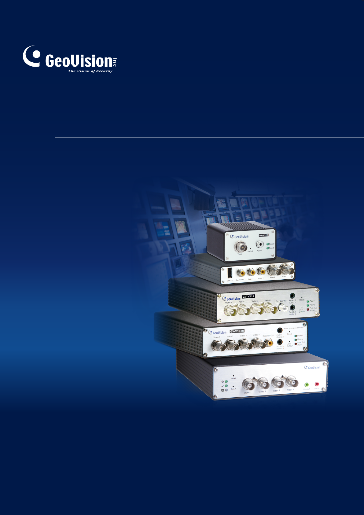
- 4-channel video inputs
- Records up to120 (NTSC) / 100 (PAL) fps at the D1 resolution
GV-VS04H
GV-VS11
GV-VS12
GV-VS14
- H.264 video compression
- Two-way audio
- GPS tracking / Wiegand access control support
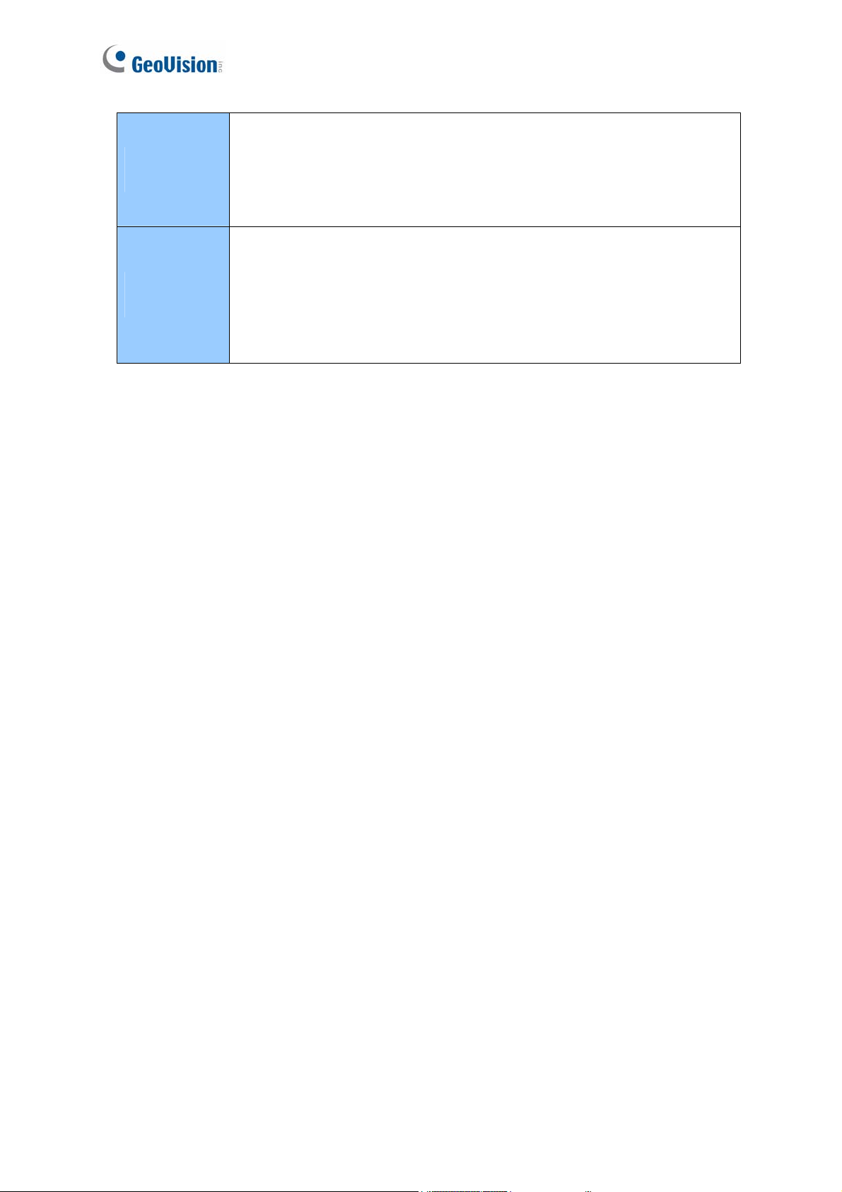
- 1-channel video input
- Records up to 30 (NTSC) / 25 (PAL) fps at the D1 resolution
- H.264, MEPG4 and MJPEG video compression
- One-way audio
- Dual streams
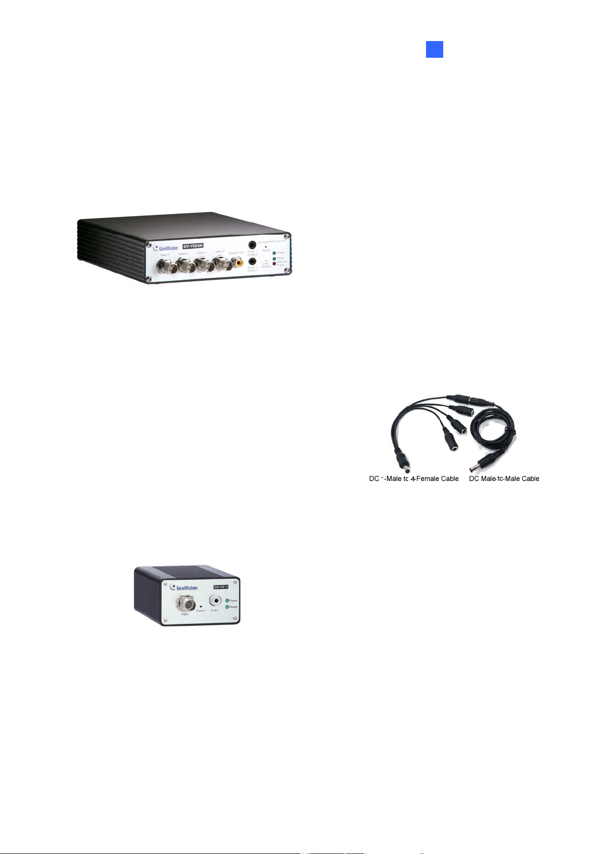
- 2-channel video inputs
- Records up to 60 (NTSC) / 50 (PAL) fps at the D1 resolution
- MEPG4, MJPEG and H.264 video compression
- Two-way audio
- GPS tracking support
- 4-channel video inputs
- Records up to120 (NTSC) / 100 (PAL) fps at the D1 resolution
- H.264 and MJPEG video compression
- Two-way audio
- GPS tracking / Wiegand access control support
- Dual streams
Page 10
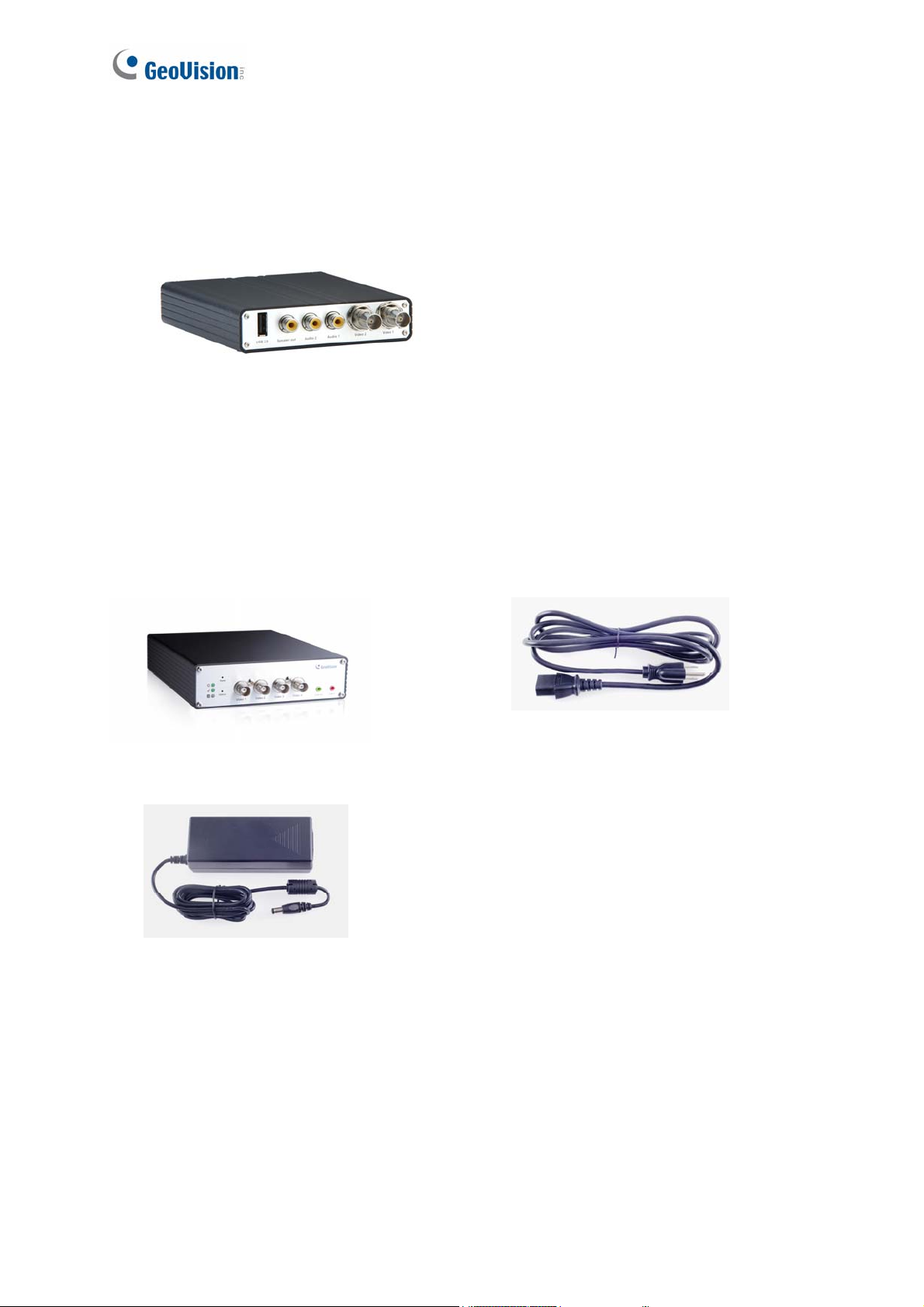
GV-VS2420
(AHD)
GV-VS2400
(TVI)
- 4-channel video inputs
- Records up to120 (NTSC) / 100 (PAL) fps at AHD 1080p resolution
- H.264
- Two-way audio
- Dual streams
- 4-channel video inputs
- Records up to120 (NTSC) / 100 (PAL) fps at HD-TVI 1080p
resolution
- H.264
- Two-way audio
- Dual st
reams
2
Page 11
1.2 Packing List
1.2.1 GV-VS04H / GV-VS14
Introduction
1
1. GV-VS04H / GV-VS14
2. AC Power Cord x 1DC Male-to-Male
Cable (for powering on the camera
through GV-Video Server) x 1
3. Power Adaptor x 1
4. Wall Hook x 1
5. Conical Anchor x 4
6. Screw x 4
7. 3.5 mm Stereo to RCA Cable x 2
8. GV-Video Server Software CD/DVD x 1
9. GV-NVR Software CD/DVD x 1
Note: The DC Male-to-Male Cable is used to power on
the camera through the GV-Video Server. You can also
optionally purchase three more DC Male-To-Mare
Cables and one DC 1-Male to 4-Female Cable to power
on four cameras through the GV-Video Server.
1.2.2 GV-VS11
1. GV-VS11
2. Power Adaptor x 1
3. GV-Video Server Software CD/DVD x 1
4. GV-NVR Software CD/DVD x 1
3
Page 12
1.2.3 GV-VS12
1. GV-VS12
2. AC Power Cord x 1
3. Power Adaptor x 1
4. I/O Cable with RJ-45 Connector x 1
5. Wall Hook x 1
6. Conical Anchor x 4
1.2.4 GV-VS2420 / 2400
1. GV-VS2420 / 2400
3. Power Adaptor x 1
7. Screw x 4
8. Sticker (for positioning conical anchors) x 1
9. GV-Video Server Software CD/DVD x 1
10. GV-NVR Software CD/DVD x 1
2. AC Power Cord x 1
4. GV-Video Server Software CD/DVD x 1
4
5. GV-NVR Software CD/DVD x 1
6. Warranty Card
Page 13

Introduction
1
1.3 Compatible Products and System Requirements
1.3.1 Compatible GeoVision Software
This section introduces the compatible applications for GV-VS2420 /2400.
Surveillance System & Network Storage
y GV-System (GV-DVR/NVR): V8.6.2 with patch files or later
y GV-VMS: V15.10 or later
y GV-Recording Server: V1.3.0.0 or later (Upcoming)
y GV-Control Center: V3.4.0.0 or later (Upcoming)
Mobile App
y GV-Eye for iOS and Android: V2.0 or later
Edge Recording
y GV-Edge Recording Manager for Windows: V1.2.0.0 or later (Upcoming)
1.3.2 System Requirements
To access the Web interface of the GV-Video Server, ensure your PC is in good
network connection and use one of the following Web browsers:
For GV-VS04H and GV-VS11 / 12 / 14
y Microsoft Internet Explorer 7.x or later
For GV-VS2420 / 2400
y Microsoft Internet Explorer 8.x or later
y Google Chrome
y Mozilla Firefox
y Safari
y Microsoft Edge
Note:
1. For the users of Internet Explorer 8 or later, additional settings are required. For
details, see Appendix A.
2. Internet Explorer 10 is only supported by GV-VS11 version 1.05, GV-VS12 version
1.09, GV-VS14 version 1.03.
3. For users of non-IE browsers using GV-VS2420 / 2400, download GV-Web Viewer
to access full functioning user interface. For details, see 3.1 Accessing Your
Surveillance Images.
5
Page 14

1.4 PoE Support
The models supporting PoE (Power over Ethernet) include:
• GV-VS04H and GV-VS12
When the PoE (Power over Ethernet) function is used, please note:
• The I/O terminal functions cannot work. Don’t connect any devices to the I/O terminal
block on the rear panel of the unit.
• External power supply is required for USB storage device when used for recording.
See “Power over Ethernet” in Specifications later in this manual before purchasing a PoE
adaptor.
1.5 GPS Support
Attached with the GV-GPS Receiver, the GV-Video Server allows you to perform vehicle
tracking on Google Maps. The models supporting GPS function include:
• GV-VS04H, GV-VS12 and GV-VS14.
Different models of the GV-Video Server support different interfaces:
• UART: GV-VS04H and GV-VS14
• RS-232: GV-VS12
6
Page 15
Introduction
1
1.6 Options
Optional devices can expand your GV-Video Server’s capabilities and versatility. Contact
your dealer for more information.
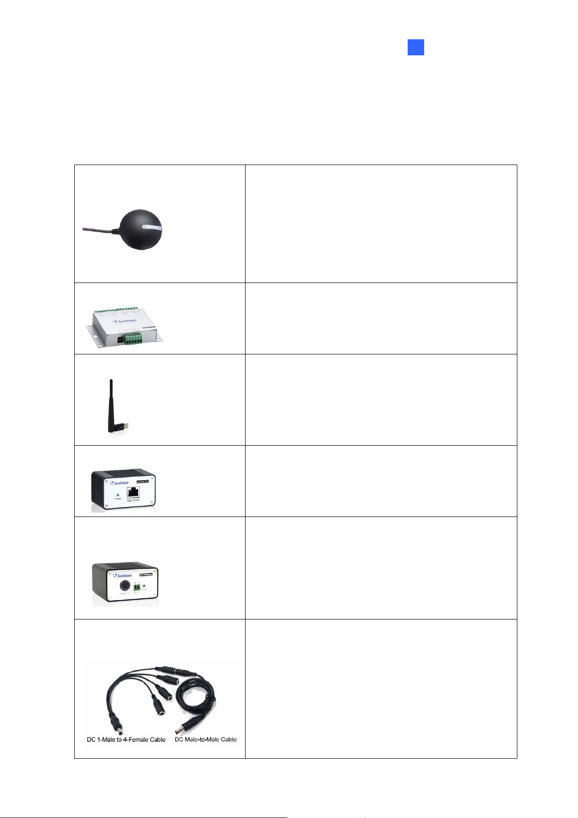
The GV-GPS Receiver is a Global Position System
GV-GPS Receiver
receiver. With the GV-GPS Receiver, you can perform
GPS tracking and location verification of the GV-Video
Server. Two types of interfaces are available: UART
(for GV-VS04H/GV-VS14) and RS-232 (for GV-VS12).
Note: The GV-GPS Receiver is not supported by GVVS11 and GV-VS2420 / 2400.
GV-Relay V2
GV-WiFi USB Adaptor
GV-PA191 PoE Adaptor
GV-VR605A DC Voltage
Regulator
Working with the GV-Relay V2, the GV-Video Server
is capable of driving the loads of relay outputs over 5
volts.
The WiFi USB Adaptor is designed to connect the GV
IP devices, such as GV-Video Server or GV-Compact
DVR, to the wireless network.
The GV-PA191 is designed to provide power to the IP
device through a single Ethernet cable. The GVPA191 is only supported by GV-VS04H and GV-VS12.
With the GV-VR605A, you can install GV-Video Server
in the car. The GV-VR605A will supply and maintain a
12V voltage to the GV-Video Server and its connected
cameras.
DC Male-to-Male Cable
DC 1-Male to 4-Female Cable
Note: The GV-VR605A is not supported by GVVS2420 / 2400.
Only supported by GV-VS2420 / 2400, the DC Maleto-Male Cable is used to power on the camera through
the GV-Video Server.
For instance, you can purchase four DC Male-to-Male
Cables and one DC 1-Male to 4-Female Cable to
power on four cameras through the GV-Video Server.
7
Page 16
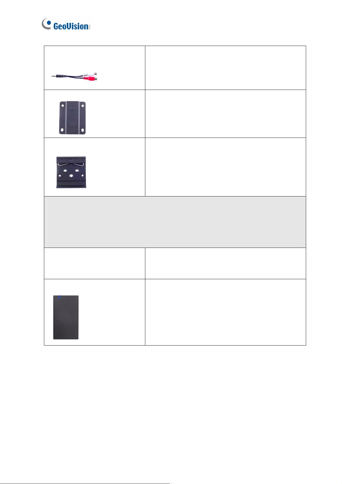
3.5 mm Stereo to
RCA Cable
Wall Hook
Only supported by GV-VS2420 / 2400, the 3.5 mm
Stereo to RCA Cable is served as an audio adapter for
microphones with RCA connectors.
Only supported by GV-VS2420 / 2400, the Wall Hook
is used to mount the device to the wall.
Din-rail Hook
Only supported by GV-VS2420 / 2400, the Din-rail
Hook is used to mount the device to a cabinet.
Access Control Series
The GV-Video Server can work with the Wiegand-interface card reader to send cardholder
data to the central monitoring stations Center V2 and Vital Sign Monitor, as well as GVSystem(GV-DVR/ NVR). The following devices are only supported by GV-VS04H and GVVS14.
GV-Reader
GV-R1352 Card Reader
GV-Reader includes transmit-receive antenna and
electronics. Featured with the Wiegand output, the unit
is compatible with any standard access control panel.
The GV-R1352 is a card reader designed to recognize
identification cards. Featured with the Wiegand output,
the unit can be connected to any standard access
control panel. The GV-R1352 comes with a weather
sealed and IP66 compliant housing for outdoor use.
8
Page 17
1.7 Physical Description
This section identifies the various components of the GV-Video Server.
1.7.1 Front View
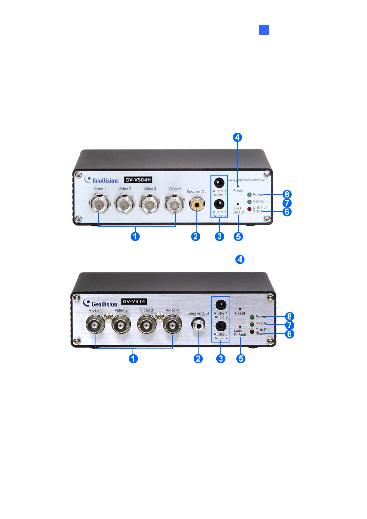
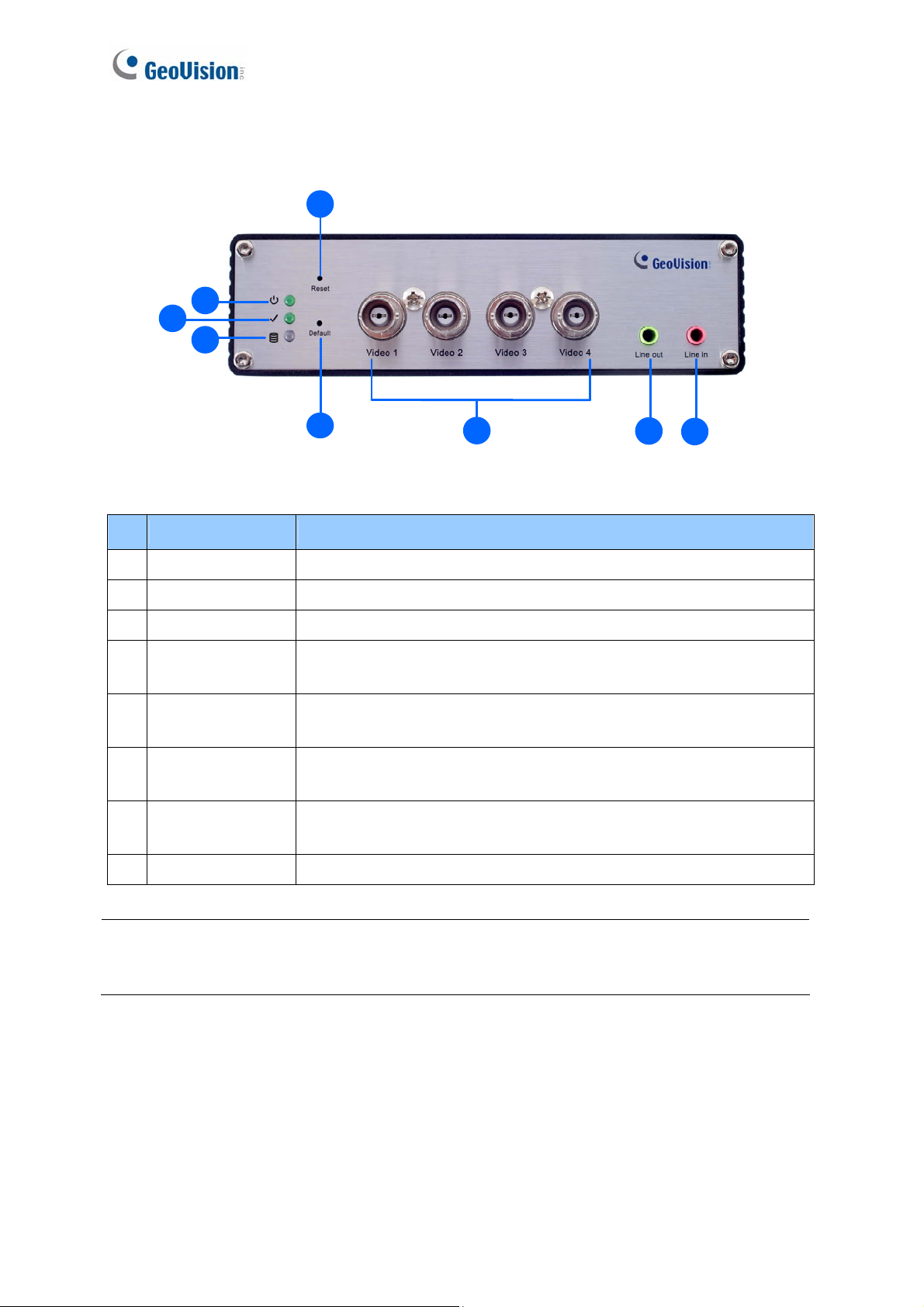
1.7.1.1 GV-VS04H / GV-VS14
Introduction
1
Figure 1-1
9
Page 18
No. Name Function
Video Input 4 plugs for video inputs.
1
Speaker Output A plug for the speaker device.
2
Audio Input Each plug is for 2 audio inputs.
3
4 Reset
5 Default Button
Disk Full/Fault
6
LED
7 Ready LED
Power LED This LED is on, indicating the power is supplied.
8
It reboots the GV-Video Server, and keeps all current
configurations.
It resets all configurations to their factory settings. See 6.4
Restoring to Factory Default Settings.
This LED is on, indicating the hard drive is full or faulty.
This LED is on, indicating the GV-Video Server is ready for
connection.
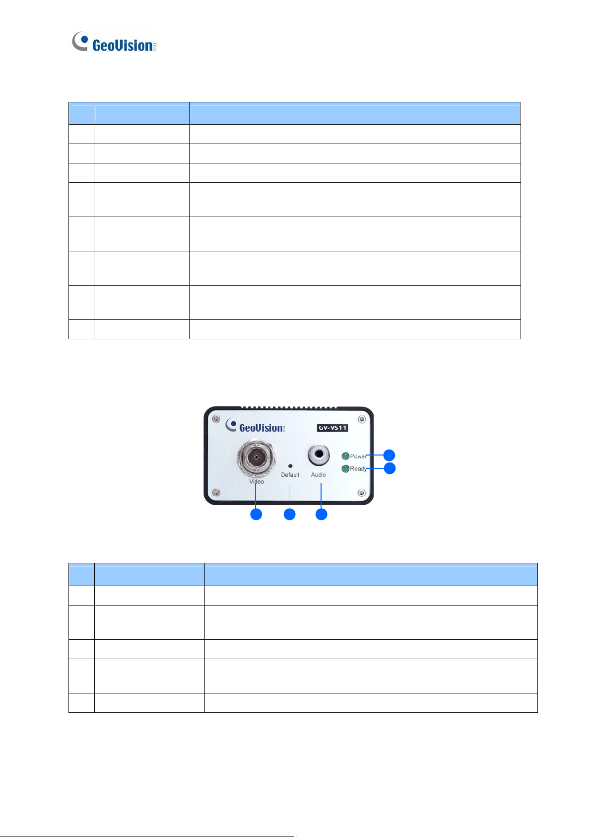
1.7.1.3 GV-VS11
5
4
1
No. Name Function
1 Video Input 1 plug for video input.
2 Default Button
3 Audio Input 1 plug for audio input.
4 Ready LED
5 Power LED This LED is on, indicating the power is supplied.
It resets all configurations to their factory settings. See 6.4
Restoring to Factory Default Settings.
This LED is on, indicating the GV-Video Server is ready for
connection.
1
2
Figure 1-2
3
10
Page 19
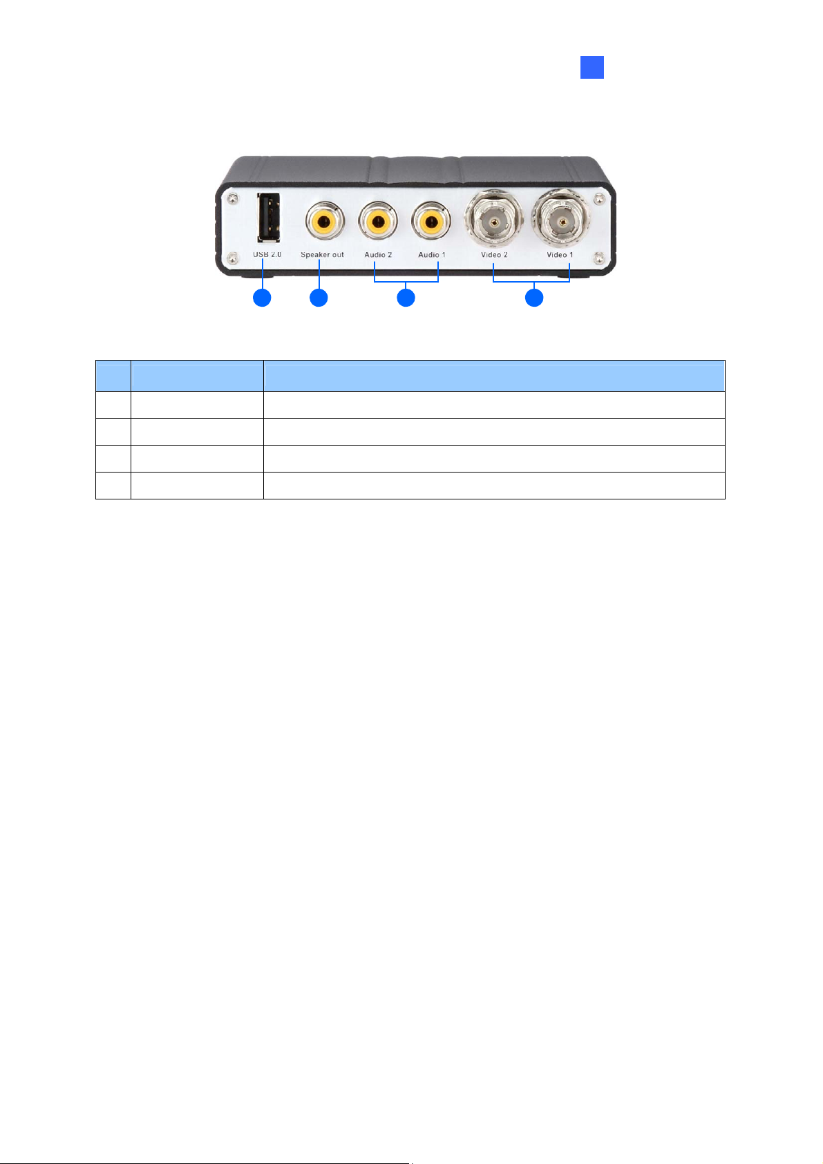
1.7.1.4 GV-VS12
12
1 2 3 4
No. Name Function
USB Port 1 USB port for installing the portable storage device.
1
Speaker Output A plug for the speaker device.
2
34
Figure 1-3
Introduction
1
Audio Input 2 plugs for audio inputs.
3
Video Input 2 plugs for video inputs.
4
11
Page 20
1.7.1.5 GV-VS2420 / 2400
4
8
7
6
5
Figure 1-4
No. Name Function
Video Input 4 plugs for video inputs.
1
Line Out A plug for Video 1 speaker device.
2
Line In A plug for Video 1 audio input.
3
4 Reset
5 Default Button
Disk Full/Fault
6
LED
7 Ready LED
Power LED This LED is on, indicating the power is supplied.
8
It reboots the GV-Video Server, and keeps all current
configurations.
It resets all configurations to their factory settings. See 6.4
Restoring to Factory Default Settings.
This LED is on, indicating the hard drive is full or faulty.
This LED is on, indicating the GV-Video Server is ready for
connection.
1
2
3
Note: When transmitting video signals over a long distance, it is highly recommended to
use 5C-FB coaxial cables or above to minimize the degradation of image quality. The
transmission distance should be within 300 m (984 ft).
12
Page 21
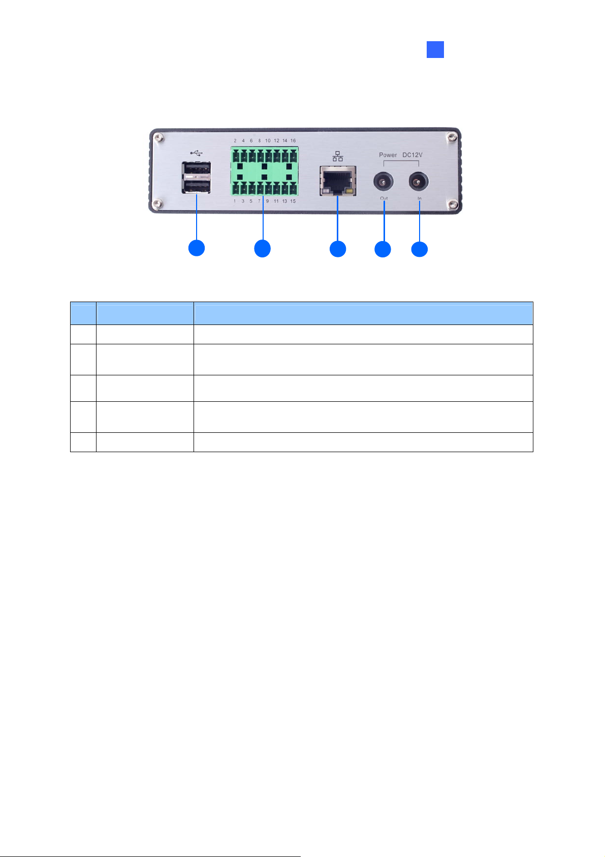
1.7.2 Rear View
1.7.2.2 GV-VS04H / GV-VS14
1 2 3
No. Name Function
Figure 1-5
4 5
Introduction
1
1 USB Port 2 USB ports for installing portable storage devices.
The connectors for digital input, relay output, PTZ camera,
2 Terminal Block
3 Ethernet Port
4 Power Out
5 Power In A plug for power input.
Wiegand device and GPS module control. See Chapter 9 Auxiliary
Device Connectors.
A plug for a 10/100 Ethernet or PoE.
Note: GV-VS14 does not support PoE function.
A plug to power on the camera, by using a DC Male-to-Male Cable,
directly through the GV-Video Server.
Note: When PoE is applied, you cannot power on the camera
through the GV-Video Server.
13
Page 22
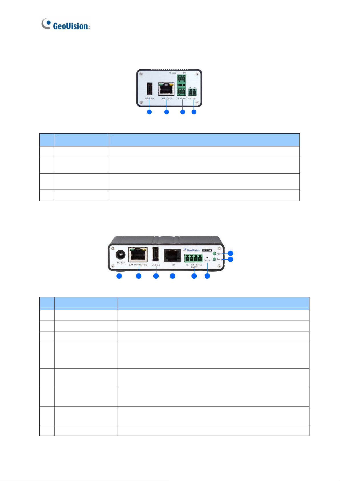
1.7.2.3 GV-VS11
1
1
1
331
2
4
Figure 1-6
No. Name Function
1 USB Port 1 USB port for installing portable storage device.
2 Ethernet Port
3 Terminal Block
A plug for inserting an Ethernet cable to build the network
connection.
The connectors for digital input, digital output and PTZ camera
control. See Chapter 9 Auxiliary Device Connectors.
4 Power In A plug for power input.
1.7.2.4 GV-VS12
8
7
1 2 3 4 5 6
Figure 1-7
No. Name Function
1 Power In A plug for power input.
2 Ethernet Port A plug for a 10/100 Ethernet or PoE.
3 USB Port 1 USB port for installing the portable storage device.
A port for digital input, relay output and PTZ camera control. Insert
4 I/O / PTZ Port
the I/O Cable with RJ-45 Connector to this port. See Chapter 9
Auxiliary Device Connectors.
RS-232
5
Terminal Block
6 Default Button
7 Ready LED
The connectors for GPS module control. See Chapter 9 Auxiliary
Device Connectors.
It resets all configurations to their factory settings. See 6.4
Restoring to Factory Default Settings.
This LED is on, indicating the GV-Video Server is ready for
connection.
8 Power LED This LED is on, indicating the power is supplied.
14
Page 23
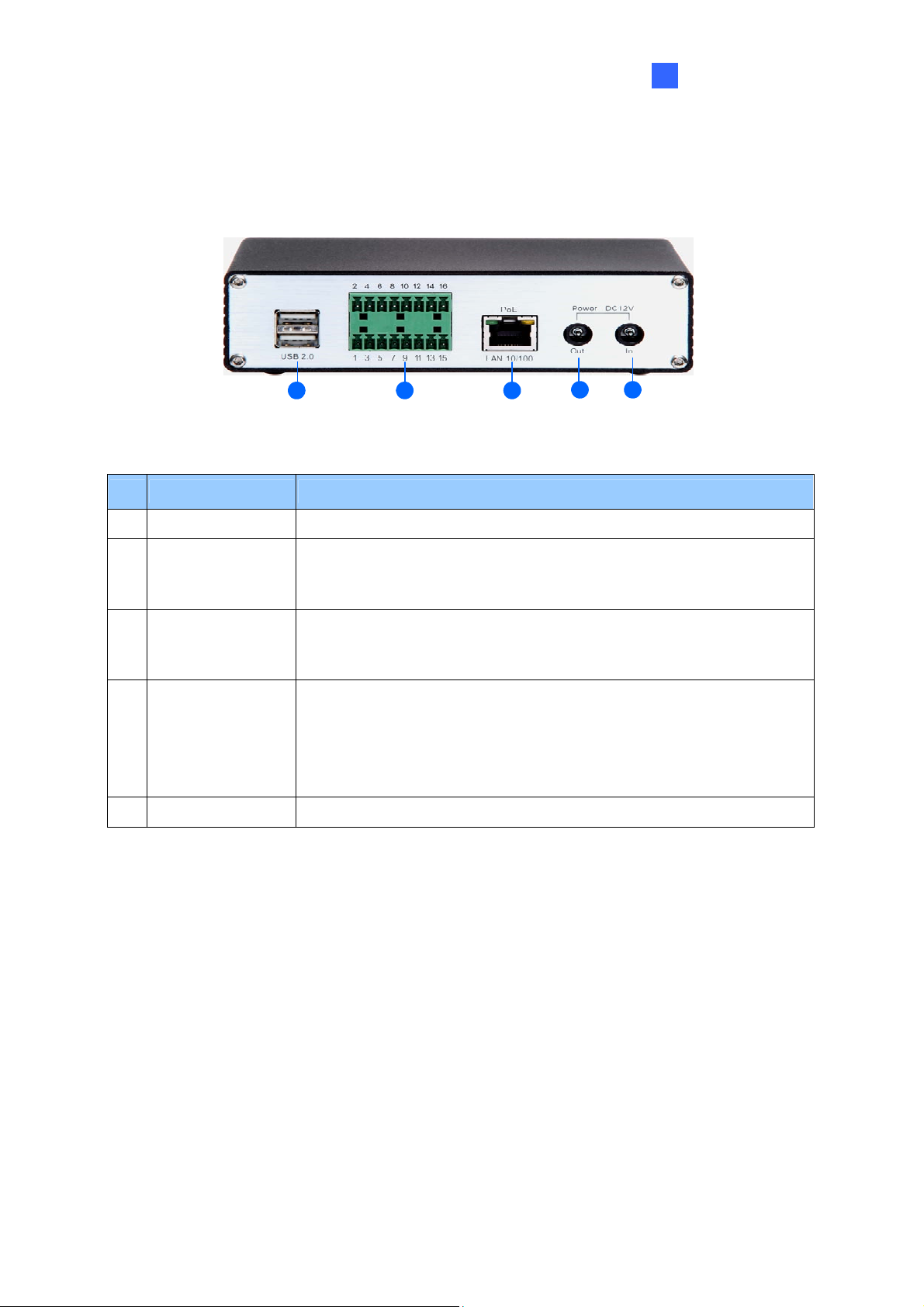
1.7.2.5 GV-VS2420 / 2400
Introduction
1
1 2
Figure 1-8
No. Name Function
1 USB Port 2 USB ports for installing portable storage devices.
2 Terminal Block
Gigabit Ethernet
3
Port
4 Power Out
5 Power In A plug for power input.
The connectors for digital input, relay output, and PTZ camera. See
Chapter 9 Auxiliary Device Connectors.
A plug for a 10/100/1000 Base-T Ethernet
A plug to power on the camera, by using the optional DC Male-toMale Cable, directly through the GV-Video Server
3
4
5
15
Page 24

Chapter 2 Getting Started
This section provides basic information to get the GV-Video Server working on the network.
2.1 Installing on a Network
These instructions describe the basic connections to install the GV-Video Server on the
network. Here we use GV-VS04H as the example to demonstrate the steps.
1 2
4
3
5
Figure 2-1
1. Connect your camera’s video output to the BNC video input.
2. Connect the microphone to the RCA audio input using the 3.5 mm Stereo to RCA
Cable.
3. Connect the hub or switch on the LAN to the unit’s 10/100 Mbps port.
4. Connect the power using one of the following methods:
z Use the supplied power adapter, connect to power.
z Use the Power over Ethernet (PoE) function. The power is provided over the
network cable.
5. Optionally connect the DC Male-to-Male Cable to power on the camera through the
GV-Video Server.
6. Wait until both Power and Ready LEDs are on.
7. By default, the GV-Video Server is assigned with an unused IP address by the DHCP
server when the unit is connected to the network. The IP address remains unchanged
unless you unplug or disconnect it from the network.
z To see how to look up the IP address assigned by the DHCP server, see 2.2
Checking the IP Address.
z If the GV-Video Server is installed in a LAN without the DHCP server, the default IP
address 192.168.0.10 will be applied. To change the IP address, see 2.3 Changing
the IP Address.
16
Page 25

Getting Started
2
Note:
1. The GV-VS11 / 14 and GV-VS2420 / 2400 do not support PoE function.
2. The DC Male-to-Male Cable and 3.5 mm Stereo to RCA Cable are only supplied for
GV-VS04H and GV-VS14. Optionally purchase these accessories for GV-VS2420 /
2400.
3. The GV-Video Server cannot work with the microphone requiring power from the unit.
Use the microphone that has external power supply.
4. When PoE is applied, you cannot power on the camera through the GV-Video Server.
17
Page 26
2.2 Checking the IP Address
By default, an unused IP address is automatically assigned by the DHCP server to the
GV-Video Server when connecting to the network. Follow the steps below to look up the IP
address and access the Web interface.
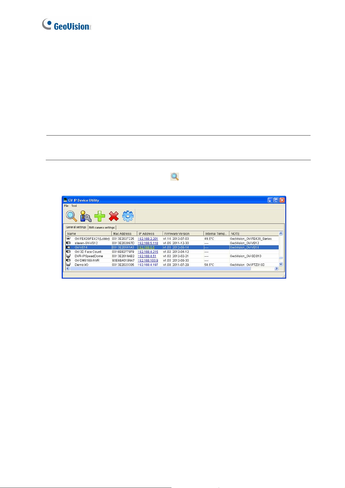
1. Install the GV-IP Device Utility program included on the Software CD/DVD.
Note: The PC installed with GV-IP Device Utility must be under the same LAN with the
GV-Video Server you wish to configure
2. On the GV-IP Utility window, click the button to search for the IP devices
connected in the same LAN. Click the Name or Mac Address column to sort.
Figure 2-2
3. Find the GV-Video Server with its Mac Address to see the IP address.
4. To login, type the IP address in your web browser. A dialog box appears.
5. Type the default username and password admin.
6. Click OK to access the Web interface.
18
Page 27
Getting Started
2
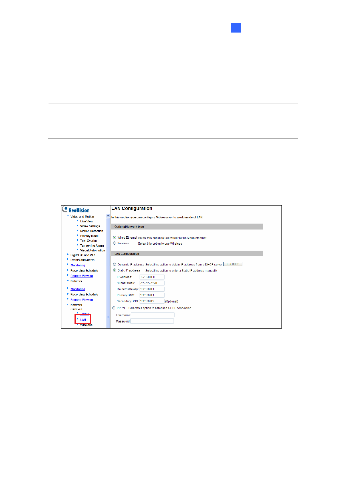
2.3 Changing the IP Address
To assign a static IP address or establish a connection to your ISP, log in the Web interface
to access the network setting page.
Note: If your router does not support DHCP, the default IP address will be 192.168.0.10.
In this case, it is strongly suggested to modify the IP address to avoid the IP address
conflict with other GV-IP device on the same LAN.
1. Open your Web browser, and type the IP address of the GV-Video Server or the
default IP address http://192.168.0.10
2. In both Login and Password fields, type the default value admin. Click Apply.
3. In the left menu, select Network and then LAN to begin the network settings.
Figure 2-3
4. To assign a static IP address, select Static IP address. Type IP Address, Subnet
Mask, Router/Gateway, Primary DNS and Secondary DNS in the Configure
connection parameters section.
5. To establish a connection to your ISP, select Use PPPoE, and type the username and
password.
6. Click Apply. The GV-Video Server is accessible by entering the assigned IP address
on the Web browser.
For details, see 4.7.1 LAN.
19
Page 28

IMPORTANT:
• PPPoE should only be enabled if you know which IP address the GV-Video
Server will get from the ISP. Otherwise, you must use the Dynamic DNS service
to obtain a domain name linked to the GV-Video Server’s changing IP address
first.
For details on Dynamic DNS Server settings, see 4.7.3 Advanced TCP/IP.
• If PPPoE is enabled and you cannot access the unit, you may have to reset it to
the factory default settings and then perform the network settings again.
To restore the factory settings, see the Default button in 1.7.1 Front View.
2.4 Configuring the Basic
Once the GV-Video Server is properly installed, the following important features can be
configured using the browser-based configuration page and are discussed in the following
sections in this manual:
• Date and time adjustment: see 4.8.1 Date and Time Settings.
• Login and privileged passwords: see 4.8.4 User Account.
• Network gateway: see 4.7 Network.
• Camera image adjustment: see 3.2.2 The Control Panel of the Live View Window.
• Video format, resolution and frame rate: see 4.1.2 Video Settings.
20
Page 29
Accessing the GV-Video Server
3
Chapter 3 Accessing the GV-Video Server
Two types of users are allowed to log in the GV-Video Server: Administrator and Guest.
The Administrator has unrestricted access to all system configurations, while the Guest
has the access to live images and network status only.
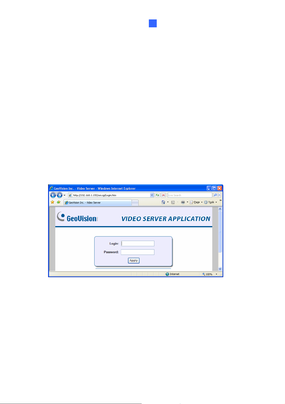
3.1 Accessing Your Surveillance Images
Once installed, your GV-Video Server is accessible on a network. Follow these steps to
access your surveillance images:
1. Open a Web browser.
2. Enter the IP address or domain name of the GV-Video Server in the
Location/Address field of your browser.
Figure 3-1
3. Enter the login name and password.
• The default login name and password for Administrator are admin.
• The default login name and password for Guest are guest.
4. The live view web page is now displayed on your browser.
• For Internet Explore, a video image, similar to the example in Figure 3-2, is now
displayed in your browser.
21
Page 30

• Only supported by GV-VS2420 / 2400. For Mozilla Firefox, Google Chrome, Safari,
or Microsoft Edge. Click GV-Web Viewer, type in the IP address of your camera,
and click Connect to access the full functioning user interface.
Note:
1. GV-VS04H and GV-VS11 /12 / 14 are only supported by Microsoft Internet
Explorer 7.x or later.
2. To enable the updating of images in Microsoft Internet Explorer, you must set
your browser to allow ActiveX Controls and perform a one-time installation of
GeoVision’s ActiveX component onto your computer.
22
Page 31

Accessing the GV-Video Server
3
3.2 Functions Featured on the Main Page
This section introduces the features of the Live View window and Network Status on the
main page. The two features are accessible by both Administrator and Guest.
Main Page of Guest Mode
▼ Video and Motion
▼ Live View
► Camera 1
► Camera 2
► Camera 3
► Camera 4
► 4 Cameras
▼ Network
► Status
Figure 3-2 Main page of GV-VS04H in Guest Mode
For GV-VS11 / 14 and GV-VS2420 / 2400 users, you can process one video stream in two
different image settings. In the Administrator mode, both streams are available. Click
Streaming 1 or Streaming 2 in the left menu to access the live view. In the Guest mode,
only one stream is available.
23
Page 32

3.2.1 The Live View Window
In the left menu, click Live View, and then select the desired Camera to see live video. .
11
10
9
8
1
2 3 4 5 6 7
Figure 3-3
No. Name Function
1 Play Plays live video.
2 Stop Stops playing video.
3 Microphone Talks to the surveillance area from the local computer.
4 Speaker Listens to the audio around the camera.
5 Snapshot
6 File Save
Takes a snapshot of live video. --- See 3.2.3 Snapshot of a Live
Video.
Records live video to the local computer. --- See 3.2.4 Video
Recording.
Switches to full screen view. Right-click the image to have these
7 Full Screen
options: Snapshot, PIP, PAP, Zoom In and Zoom Out.
--- See 3.2.5 Picture-in-Picture and Picture-and-Picture View.
8 I/O Control
9 PTZ Control
24
Starts the I/O Control Panel or the Visual Automation.
--- See 3.2.13 I/O Control.
Starts the PTZ Control Panel and the Visual PTZ.
--- See 3.2.11 PTZ Control and 3.2.12 Visual PTZ.
Page 33

Accessing the GV-Video Server
3
10 Change Camera Sets the desired camera for display.
Brings up these functions: Alarm Notify, Video and Audio
Configuration, Remote Config, Show Camera Name and
Show System
11
Menu
Note: For GV-VS2420 / 2400, only Camera 1 supports audio function.
Image Enhance. --- See 3.2.6 Alarm Notification, 3.2.7 Video
and Audio Configuration, 3.2.8 Remote Configuration, 3.2.9
Camera Name Display and 3.2.10 Image Enhancement
respectively.
3.2.2 The Control Panel of the Live View Window
To open the control panel of the Live View window, click the arrow button or on top of
the viewer. You can access the following functions by using the right and left arrow buttons
on the control panel.
Click the arrow button to display the control panel.
Click the right and left
arrow buttons to change
the page of the control
panel.
Figure 3-4
[Information] Displays the version of the Video Server, local time of the local computer,
host time of the Video Server, the number of users logging in to the Video Server and the
OCX registration path.
[Video] Displays the current video codec, resolution and data rate.
[Audio] Displays the audio data rates when the microphone and speaker devices are
enabled. For GV-VS2420 / 2400, only Camera 1 supports audio function.
25
Page 34

[I/O Control] Provides a real-time graphic display of the input and output status. You can
force the output to be triggered by double-clicking its icon.
[Alarm Notify] Displays the captured images by sensor triggers and/or motion detection.
For this function to work, you must configure the Alarm Notify settings first. See 3.2.6
Alarm Notification.
[Camera Adjustment] Allows you to adjust the image quality.
[GPS] For details see 6.3 GPS Tracking. This function is not supported by GV-VS11 and
GV-VS2420 / 2400.
[Download] Allows you to install the programs from the hard drive. This function is not
supported by GV-VS2420 / 2400.
[Internal Temperature] Displays the current chipset temperature inside the camera. This
function is only available for GV-VS2420 / 2400.
26
Page 35

Accessing the GV-Video Server
3
3.2.3 Snapshot of a Live Video
To take a snapshot of live video, follow these steps:
1. Click the Snapshot button (No. 5, Figure 3-3). The Save As dialog box appears.
2. Specify Save in, type the File name, and select JPEG or BMP as Save as Type. You
may also choose whether to display the name and date stamps on the image.
3. Click the Save button to save the image in the local computer.
3.2.4 Video Recording
You can record live video for a certain period of time to your local computer.
1. Click the File Save button (No. 6, Figure 3-3). The Save As dialog box appears.
2. Specify Save in, type the File name, and move the Time Period scroll bar to specify
the time length of the video clip from 1 to 5 minutes.
3. Click the Save button to start recording.
4. To stop recording, click the Stop button (No. 2, Figure 3-3).
3.2.5 Picture-in-Picture and Picture-and-Picture View
The full screen mode provides two types of close-up views: Picture-in-Picture (PIP) and
Picture-and Picture (PAP). The two views are useful to provide clear and detailed images
of the surveillance area.
To access this feature:
• Click the Full Screen button (No. 7, Figure 3-3). Right-click the full screen to have the
options of PIP and PAP.
• Right-click the live view to have the options of PIP and PAP.
27
Page 36

Picture-in-Picture View
With the Picture in Picture (PIP) view, you can crop the video to get a close-up view or
zoom in on the video.
Navigation box
Inset window
Figure 3-5
1. Select PIP. An inset window appears.
2. Click the insert window. A navigation box appears.
3. Move the navigation box around in the inset window to have a close-up view of the
selected area.
4. To adjust the navigation box size, move the cursor to any of the box corners, and
enlarge or diminish the box.
5. To exit the PIP view, right-click the image and click PIP again.
28
Page 37

Accessing the GV-Video Server
3
Picture-and-Picture View
With the Picture and Picture (PAP) view, you can create a split video effect with multiple
close-up views on the image. A total of 7 close-up views can be defined.
Figure 3-6
1. Select PAP. A row of three inset windows appears at the bottom.
2. Draw a navigation box on the image, and this selected area is immediately reflected
in one inset window. Up to seven navigation boxes can be drawn on the image.
3. To adjust a navigation box size, move the cursor to any of the box corners, and
enlarge or diminish the box.
4. To move a navigation box to another area on the image, drag it to that area.
5. To change the frame color of the navigation box or hide the box, right-click the image,
select Mega Pixel Setting and click one of these options:
Display Focus Area of PAP Mode: Displays or hides the navigation boxes on
the image
Set Color of Focus Area: Changes the color of the box frames.
6. To delete a navigation box, right-click the desired box, select Focus Area of PAP
Mode and click Delete.
7. To exit the PAP view, right-click the image and click PAP again.
29
Page 38

3.2.6 Alarm Notification
After input triggers and motion detection, you can be alerted by a pop-up live video and
view up to four captured images.
Pop-up live video
Captured images
Figure 3-7
To configure this function, click the Show System Menu button (No. 11, Figure 3-3), and
select Alarm Notify. This dialog box appears.
Figure 3-8
Motion Notify: Once motion is detected, the captured images are displayed on the
control panel of the Live View window.
I/O Alarm Notify: Once the input device is triggered, the captured images are
displayed on the control panel of the Live View window. For this function to work, the
Administrator needs to install the input device properly. See 4.2.2 Input/Output
Settings.
Alert Sound: Activates the computer alarm on motion and input-triggered detection.
Auto Snapshot: The snapshot of live video is taken every 5 seconds on motion and
input-triggered detection.
File Path: Assigns a file path to save the snapshots.
30
Page 39

Accessing the GV-Video Server
3
3.2.7 Video and Audio Configuration
You can enable the microphone and speaker for two-way audio communication and adjust
the audio volume. To change audio configuration, click the Show System Menu button
(No. 11, Figure 3-3), and select Video and Audio Configuration.
Note:
1. The GV-VS11 only supports one-way audio communication.
2. For GV-VS2420 / 2400, only Camera 1 supports audio function.
Audio Configure: You can enable the microphone and speaker, and adjust the audio
volume.
Camera: Sets the number of frames to keep in live view buffer. Keeping more frames
for live view buffer can ensure a smooth live view, but the live view will be delayed for
the number of frames specified.
Figure 3-9
3.2.8 Remote Configuration
You can upgrade firmware over the Internet. Click the Show System Menu button (No. 11,
Figure 3-3), and select Remote Config. The Remote Config dialog box will appear.
[Firmware Upgrade] In this tab, you can upgrade the firmware over the network. For
details, see Chapter 6 Advanced Applications.
31
Page 40

3.2.9 Camera Name Display
To display the camera name on the image, click the Show System Menu button (No. 11,
Figure 3-3), and select Show Camera Name.
3.2.10 Image Enhancement
To enhance the image quality of live video, click the Show System Menu button (No. 11,
Figure 3-3), and select Image Enhance. This dialog box appears.
Figure 3-10
De-Interlace: Coverts the interlaced video into non-interlaced video.
De-Block: Removes the block-like artifacts from low-quality and highly compressed
video.
Enable DirectDraw: Activates the DirectDraw function.
32
Page 41

Accessing the GV-Video Server
3
3.2.11 PTZ Control
To open the PTZ control panel, click the PTZ Control button (No. 9, Figure 3-3) and select
PTZ Control Panel. Different PTZ devices have different functions, so the features
included in the Option button may vary.
This feature is only available when the PTZ is set ahead by the Administrator. For details,
see 4.2.1 PTZ Settings.
Exit
Pan / Tilt Control
Zoom
Focus
Option (Settings for Auto Mode,
Preset, Port, Speed and etc.)
Preset Switch Panel
Figure 3-11
33
Page 42

3.2.12 Visual PTZ
In additional to the PTZ control panel, you can display a visual PTZ control panel on the
image. This feature is only available when the PTZ is set ahead by the Administrator. For
details, see 4.2.1 PTZ Settings.
Figure 3-12
¾ To access this feature, click the PTZ Control button (No. 9, Figure 3-3) and select
Visual PTZ.
¾ To change the panel settings, click the green PTZ button on the top left corner. You
will have these options:
[PTZ Control Type]
Type 1: In this mode when you place the mouse arrow on the four directions, i.e.
north, south, east, west, the speed indicator of five levels will appear. Click and
hold on the required level of movement and the camera will move as per the
specific speed.
Type 2: In this mode with the mouse click, the PTZ control panel will appear. The
movement of the camera will depend on the speed of the mouse movement.
[Configure]
Set Color: Changes the color of the panel. Three kinds of colors are available:
34
Red, Green and Blue.
Transparent Degree: Adjusts the transparency level of the panel. Ten levels
range from 10% (fully transparent) to 100% (fully opaque).
Page 43

Accessing the GV-Video Server
3
3.2.13 I/O Control
The I/O Control window provides real-time graphic displays of camera and I/O status, and
alarm events. Additionally, you can force output to be triggered.
Figure 3-13
¾ To display the I/O control window, click the I/O Control button (No. 8, Figure 3-3).
¾ The Alarm List is displayed in three levels. The first level indicates date, the second
indicates time, and the third indicates alarm ID. Clicking the Reset button will clear the
list.
¾ To trigger an output device, highlight an output and then click the Output button.
35
Page 44

3.2.14 Visual Automation
The Visual Automation allows you to change the current state of the electronic device by
simply clicking on its image, e.g. turning the light ON. This feature is only available when
the Visual Automation is set ahead by the Administrator. For details, see 4.1.7 Visual
Automation.
Figure 3-14
¾ To access this feature, click the I/O Control button (No. 8, Figure 3-3) and select
Visual Automation.
¾ To change the style of the set areas, click the green I/O button on the top left corner.
You will have these options:
Show All: Displays all set areas.
Rect Float: Embosses all set areas.
Set Color: Changes the frame color of all set areas
3.2.15 Network Status
To view the network status, in the left menu, click Network and select Status.
Figure 3-15
36
Page 45

Administrator Mod e
4
Chapter 4 Administrator Mode
The Administrator can access the system configuration via the Internet. E
configurations are involved in the system configuration:
and PTZ, Events and Alerts, Monitoring, Recording Schedule, Remote ViewLog,
Network, and Management.
Video and Motion, Digital I/O
ight categories of
Figure 4-1
37
Page 46

List of Menu Options
Find the topic of interest by referring to the section number prefixed to each option. The
available options vary among v models.
4.1 Video and Motion
4.2 Digital I/O and PTZ
4.3 Events and Alerts
ideo server
4.1.1 Multicas
4.1.2 Video
4.1.3 Moti
4.1.4 Privacy
4.1.5 Text Ove
4.1.6 Tampering Alarm
4.1.7 Visual Auto
4.2.1
4.2.2
4.2.
4.2.4 Bu
4.3.1 E-
4.3.2 FTP
4.3.3 Center V2
4.3.4 Vital Si
4.3.5 GV-G
4.3.6 Backup Center
4.3.7 Video Gateway / R
4.3.8 ViewLog Ser
4.3.9 3GPP / RTSP
on Detection
PTZ Settings
Input/Output Settings
3 GPS / Wiegand
zzer
mail
Settings
gn Monitor
IS
t
Mask
rlay
mation
han4.1.8 Video C
nel Source Settings
ecording Server
ver
4.4 Monitoring
4.5 Recording Schedule
4.6 Remote ViewLog
4.7 Network
4.8 Management
4.5.1 Recordin
I/O Monitoring Settings
4.5.2
4.7.1 LAN
4.7.2 Wireless-Clien
4.7.3 Advanced
4.7.4 UMTS
4.7.5 Multicast
4.7.6 IP F
7 SNM
4.7.
4.8.1 Da
4.8.2 GPS Maps Settings
4.8.3 Storage Settings
4.8.4 User Account
4.8.5 Log Information
4.8.6 System Log
4.8.7 Tools
4.8.8 Language
te and Time Settings
g Schedule Settings
t Mode
TCP/IP
ilte
r
P Setting
38
Page 47

Comparison Table for Major Functions
Administrator Mod e
4
The options or functions on the left menu of the Web interface (Figure 4-1
depended on mo
dels. The table below provides the information of major differences in
supported functions.
Model
GV-VS04H GV-VS11 GV 2 -VS1 G -VS14 V
(FW V1.03 or
later)
(FW V1.0
or later)
(FW V1.02 (FW V1.0 or
or later) later)
Function
Dual Streams
Wiegand
Buzzer
Multicast
Tampering
Alarm
No Yes
Yes No No Yes
No No No No Yes
Yes Yes Yes Yes
Yes Yes Yes Yes
No Yes Yes
) may vary
GV-VS2420
/ 2400
No
No
Yes
Watermark
Text Overlay
Video
Channe
Source S
ettings
System Log
GV-B
ackup
Center
Connecti
on
GV-Video
Gateway
Connection
GV-GIS
Connection
Yes Yes Yes Yes Yes
Yes Yes Yes Yes Yes
l
Yes
No No No
Yes Yes Yes Yes
Yes Yes Yes Yes
Yes Yes Yes Yes
Yes
No Yes Yes
No
No
Yes
Yes
No
39
Page 48

4.1 Video and Motion
This section includes the video image settings and introduces how the ima
managed by using Multicast, Motion Dete
Automation and Video Channel Source Settings.
ction, Privacy Mask, Tampering Alarm, Visual
ges can be
4.1.1 Multicast
Note this function is only available for GV-VS04H (Firmware Version 1.03 or later), GVVS11, GV-VS12 (Firmware Version 1.05 or later) and GV-VS14.
The Multicast view allows the GV-Video Server receiving video and audio streams from a
multicast group. It also enables the GV-Video Server to receive audio broa
hosts in the multicast group
To join a multicast group and listen to audio broadcasting, it is required to activate the
related settings in 4.7.5 Multicast.
.
dcast from the
Figure 4-2
1. The host(s), in the multicast group, is displayed automatically on the host list. If you
Configure Button
Host List
cannot see any host displayed, click the Configure button, select General Setu p , select
Multicast and ensure the relevant IP address, port number and network card are
correctly configured.
40
Page 49

Administrator Mod e
4
2. Expand the Host folder and drag the desired cameras to the screen for display. If the host
has already set a password, you will be promoted to enter it at this step.
3. To receive audio broadcasting, first ensure a speaker is properly insta
computer. Then click the Configure button, select General Setup, selec
broadcast
configured.
4. To save the current settings of screen div
the Configure button, select Video List Setup, and select Export. You can also select
Import to apply the
audio, and ensure the broadcast IP address and port number are correctly
ision and camera display for future use, click
pre-defined settings.
lled on the local
t Receive
4.1.2 Video Settings
For GV-VS11 / 14 and GV-VS2420 / 2400, it can simultaneously process one
in two different codec and resolutions. The dual-stream design benefits for lo
bandwidth environment, allowing Streaming 2 set with lower resolution and codec for live
streaming, and Streaming 1 set with highest resolution and codec H.264 for best recording
quality. Two setting pages Streaming 1 and Streaming 2 are provided for separate setup.
video stream
wer
41
Page 50

42
Figure 4-3
Page 51

Administrator Mod e
4
[Name]
Rename the camera. The camera name will appear on the Live View. To display the
camera name, see 3.2.9 Camera Name Display.
[Connection Template]
Note this function is not supported by GV-VS2420 / 2400. S
elect the type of your network
connection. Unless you select Customized, this option will automatically bring up the
recommended video resolution, frame rate, bandwidth and GOP size.
Due to the bandwidth limitation for mobile phone connections, only the video
352 x 240 (352 x 288) are su
rate or better video quality you will get. But no
pported. The higher resolution you select, the higher frame
te that your mobile phone must support the
resolutions
video resolution you wish to select.
Connection t connect
emplates for mobile phone ions:
3GPPv7, Msview V2 / V3, Ssview V3 and GView V2 Supported
Resolution Frame Rate
NTSC 352 x 240 5
PAL 352 x 288 5
[Video Signal Type]
Video Format: Note this function is only available for GV-VS11 and GV-VS12. Select
a codec for the video stream.
A ype
uto detect signal t on booting: Automatically detects the type of video input is
NTS r GV-V
C or PAL. Fo S04H and GV-VS 11 / 12 /14, select to enable this function.
For 2400, this function is enabled by default.
GV-VS2420 /
The sup vary from model to model.
ported codecs
Model Codec
GV-VS04H
GV-VS11
GV-VS12
GV-VS14
GV-VS2420 / 2400
H.264
H.264, MPEG4 , MJPEG (Streaming 1 and 2)
H.264, MPEG4 , MJPEG
H.264 (Streaming 1), MJPEG (Streaming 2)
H.264 (Streaming 1 and 2)
43
Page 52

The image resolution v rom model to model. aries f
Models
GV-VS04H,
GV-VS11 / 12 / 14
GV-VS2420
GV-VS2400
NTSC PAL
704 x 480 704 x 576
704 x 480 de-interla 704 x 576 de-interlace ce
352 x 240 352 x 288
x11 176 4
176 2 x 14
NTSC
HD, AHD
NTSC
SD
PAL PAL
HD, AHD SD
1920 x 1080 960 x 480 1920 x 1080 960 x 576
1280 x 20 128 720 x 576 720 7 x 480 0 x 720
640 x 3 480 640 480 x 288 60 x 240 x 360
2 60 8 360 x 288 448 x 52 3 x 240 44 x 252
NTSC NTSC PAL PAL
HD, TVI SD HD, TVI SD
1920 x 1080 960 x 480 1920 x 1080 960 x 576
1280 x 720 720 x 480 1280 x 720 720 x 576
640 x 360 480 x 240 640 x 360 480 x 288
448 x 252 360
x 240 448 x 252 360 x 288
The frame rate va om m o model. ries fr odel t
Models
GV-VS04H,
GV-VS11 / 12 / 14
GV-VS2420 / 2400
Format Frame Rate
NTSC
PAL
NTSC
PAL
1, 2, 3, 5, 7.5, 10, 15, 30
1, 2.5, 5, 8, 12.5, 25
1 ~ 30
1 ~ 25
Note:
1. The GV-VS11 / 14 and GV-VS2420 / 2400 support dual streams. By default, the dual
streams are not enabled on GV-VS11 / 14, but enabled on GV-VS2420 / 2400.
2. For GV-VS11, four resolution options and three codec types are available for both
streaming 1 and 2.
3. The frame rate and the performance may vary depending on the number of
connections and data bitrates (different scenes).
44
Page 53

Administrator Mod e
4
[Bandwidth Management]
When using MPEG-4 or H.264, it is possible to control the bitrate, which in turn allows the
amount of bandwidth usage to be controlled.
VBR (Variable Bitrate): The quality of the video stream is kept as cons
possible at the cost o
f a varying bitrate. The bandwidth is much more efficiently used
than a comparable CBR.
y Set the image quality to one of the 5 s
tandards: Poor, Fair, Good, Great and
Excellent.
y Set the Maximal Bitrate to 1, 2, 4, 6, or 8 Mbit.
CBR (C
qualit f the stream. The bitra
resolu n.
onstant Bitrate): CBR is used to achieve a specific bitrate by varying the
y o tes available for selection depend on the image
tio
Model Bitrates for selection
GV-VS04H
3072 kbps, 2048 kbps, 1536 kbps, 1024 kbps, 768 kbps,
512 kbps, 384 kbps, 256 kbps (3GPPV7), 128 kbps (3GPPV7), 64 kbps
GV-VS14
GV-VS11
(3GPPV6), 52 kbps (3GPPV6)
2048 kbps, 1536 kbps, 1024 kbps, 768 kbps,
512 kbps, 384 kbps, 256 kbps (3GPPV7), 128 kbps (3GPPV7), 64 kbps
GV-VS12
GV-VS2420 /
2400
(3GPPV
6), 52 kbps (3GPPV6)
8192 kbps, 6144 kbps, 4096 kbps, 2048 kbps, 1024 kbps, 512 kbps.
tant as
[GOP Structure and Length]
Set the maximum number of seconds between every key frame. For, GV-VS04H and GV-
VS11 / 12 / 14, selec
length of GOP structure. For GV-VS2420 / 2400, you can directly config
t Customized in the Connection Template section before setting the
ure the settings
here.
[Record Settings]
The record settings allow you to capture images before and/or after the m
otion or I/O
event happens.
Pre-alarm record
ing time: Activates video recording before an event occurs. Set the
recording time to 1 or 2 seconds.
Post-alarm recording time: Activates video recording onto the attached USB mass
storage device after an event occurs. Set the recording time from 1 to 30 seconds.
Split Interval (Max. Video Clip): Sets the maximum time length of each recorded file
from 1 to 5 minutes.
45
Page 54

Record Audio: Activates audio recording when an event occurs.
Immediately close file: Note this function is not supported by GV-VS242
Ends a recorded file once a motion or an I/O trigger stops. When the opt
the time length of a recorded file is based on the duration of a motion or
instead of the time you set for Max. Video Clip above. Select
this option to have short
an I/O trigger
recorded files and have an easier access through mobile phones.
[Test Overlay Settings]
The text overlay settings allow you to overlay camera names, date, time, G
PS speed or
names of selected inputs on live and recorded videos.
Overlaid with camera name: Includes camera names on live and
Overlaid with date stamps: Includes date stamps on live and recorded v
Overlaid with time stamps: Includes time s
Overlaid with the GPS spee d : Includes the vehicle speed in live and rec
Note this function is on
ly available for GV-VS04H (Firmware Version 1.05 or later), GV-
tamps on live and recorded videos.
recorded videos.
VS12 (Firmware Version 1.05 or later) and GV-VS14.
0 / 2400.
ion is enabled,
ideos.
orded videos.
Overlaid with digital input description name: Includes the names of s
elected inputs
on live and recorded videos.
[Watermark] En
verify whether the video has been tampered while it was recorded and saved
able this option to watermark all recordings. The watermark allows you to
. See 6.5
Verifying Watermark.
[Apply All Settings]
Apply the settings to all cameras: Applies the same settings to other cameras. Note
this function is not supported by GV-VS2420 / 2400.
46
Page 55

4.1.3 Motion Detection
Administrator Mod e
4
Motion detection is used to generate an alarm whenever movement o
image. Y
detection.
ou can configure up to 8 areas with different sensitivity values for motion
ccurs in the video
Figure 4-4
47
Page 56

1. The default sensitivity value for the whole area is 2 for GV-VS04H and
/ 14, and
the value is 9 for GV-VS2420 / 2400. To define a different sensitivity value,
GV-VS11 / 12
click Reset.
2. Select the desired sensitivity by moving t
he slider to set the value. The higher the
value, the more sensitive the camera is to motion.
3. Drag an area on the image. Click Add when you are prompted to
confirm the setting.
4. To create several areas with different sensitivity values, repeat Steps 2 and 3.
5. Click Save to save the above settings.
6. To trigger the alarm outputs when motion is detected, s
Output 4). To activate the output settings, you must also start Camera
elect the outputs (Output 1 to
monitoring
manually or by schedule. For related settings, see 4.4 Monitoring.
7. Note this function is not supported by GV-VS2420 / 2400. To send mo
notifications to Center V2 and
Vital Sign Monitor during a particular time period,
tion detection
enable the schedule mode and click Apply.
A. Set each time frame during the day. Each day can be divided into 3
time frames,
represented by Span 1 to Span
B. Enable the Weekend option to have a whole-day monitoring on the
Define whether your weekend includes or
3.
weekend.
Saturday and Sunday Only Sunday.
C. Click Apply to save the above settings.
Note: For GV-VS11 and GV-VS12 users, this function does not wo
codec is selected in the Video Signal Type field (Figure 4-1). For detai
rk when MJPEG
ls, see 4.1.2
Video Settings.
8. If you want to ignore environmental changes such as rain or snow, select Ignore
environmental changes. Note this function is only available for GV-VS2420 / 2400.
9. The Noise Tolerance function is enabled by default. It ignores video noise when the
light intensity changes. Note this function is only available for GV-VS2420 / 2400.
48
Figure 4-4-1
Page 57

Administrator Mod e
4
4.1.4 Privacy Mask
The Privacy Mask can block out sensitive areas from view, covering the area
boxes in both live view and recorded clips. This feature is ideal for locatio
keyboard seque
information visible.
nces (e.g. passwords), and for anywhere else you don’t want sensitive
ns with displays,
s with dark
Figure 4-5
1. Select the Enable option.
2. Drag the area(s) where you want to block out on the image. Click Add when you are
prompted to confirm the setting.
3. Click the Save button to save all the settings.
49
Page 58

4.1.5 Text Overlay
Note this option is available for GV-VS04H (Firmware Version 1.03 or
GV-VS12 (Firmware Version 1.02 or later), GV-VS14, and GV-VS2420 / 2400. .
The T
ext Overlay function allows you to type any text in any place on the camera view. Up
to 16 text messages can be created. The overlaid text will also be saved in the recorded
images.
later), GV-VS11,
Figure 4-6
1. Select the Enable option.
2. Click any place on the image. This dialog box appears.
Figure 4-7
3. Type the desired text, and click OK. The text is overlaid on the image.
4. Click on the text and drag it to any place on the image.
5. Click Set Font to modify the font style of the text.
6. Click Save to apply the settings, click Preview to preview the camera view with
50
overlaid text or click Load (Undo) to revert to a previous setting.
Page 59

4.1.6 Tampering Alarm
Administrator Mod e
4
Note this option is available for GV-VS04H (Firmware Version 1.03
or later), GV-VS11,
GV-VS12 (Firmware Version 1.02 or later), GV-VS14, and GV-VS2420 / 2400.
The Tampering Alarm is used to detect when a camera is being physically tam
alarm can be generated when the camera is moved, covered
up, or out of focus. The
pered. An
alarm approaches include the triggered output device, e-mail alerts and system buzzer. To
have the tampering alarm, first set up these alarm approaches properly:
• To trigger the output dev
select Tampering Alarm for the related camera. See Output Setting in
ice when a tamper event occurs, enable the output setting and
4.2.2
Input/Output Settings.
• To trigger the e-mail alert when a tamper event occurs, enable the e-ma
il setting and
select Tampering Alarm for the related camera. See 4.3.1 E-Mail.
• To trigger the system buzzer when a tamper event occurs, enable the buzzer setting.
See 4.2.4 Buzzer.
Figure 4-8
51
Page 60

To configure the tampering alarm:
1. Select the Enable option.
2. If you want GV-Video Server to ignore any moveme
button to drag areas on the camera view. areas, click the
3. Select the desired detection sensitivity by moving the slider. The higher the value, the
more sensitive the camera is to scene changes.
4. In the Toler ance Time of Alarm field, specify the time length allow
changes before an alarm is generated.
5. In the Duration of Alarm field, specify the duration of the alarm afte
triggered output device or system buz
6. To trigger an alarm when the
covered, select Alarm for Dark Images.
7. Click Apply to save all the settings.
8. Start monitoring to enable the function. To have buzzer alarm, it is required to start
the Camera monitoring. To have output alarm, it is required to start
For these two types of monitoring, see 4.4 Monitoring.
scene turns dark, e.g. the lens of camera has been
zer will be turned off.
nt or scene change in certain
ed for scene
r which the
Input monitoring.
When the camera has been tampered, the output device and system buzzer can be
activated. To turn off the output device and system buzzer immediately, r
setting page, and click Restart Detection.
Note: The system buzzer is only supported by GV-VS04H (Firmware Version 1.03 or
later). .
eturn to this
52
Page 61

4.1.7 Visual Automation
Administrator Mod e
4
This intuitive feature helps you automate any electronic device by trigge
output device. When you click o
change its current state, e.g. light ON.
Figure 4-9
n the image of the electronic device, you can simply
ring the connected
1. Select the Enable option.
2. Drag an area on the image of the electronic device. This dialog box appears.
Figure 4-10
3. Assign the connected module and output device. In the Note filed, type a note to help
you manage the device. Click OK to save the settings.
4. To change the frame color of the set area, click the Set Color button.
5. To emboss the set area, select Float Up; or keep it flat by selecting Normal.
6. Click the Save Set button to apply the settings.
To perform the function, see 3.2.14 Visual Automation.
53
Page 62

4.1.8 Video Channel Source Settings
Note this option is only available for GV-VS04H (Firmware Version 1.03 or l
The function allows you to assign the video input to the desired video channel for display.
Figure 4-11
ater).
54
Page 63

4.2 Digital I/O & PTZ
Administrator Mod e
4
For auxiliary device control, you can find one I/O / PTZ port along with on
terminal block for GPS control on the rear panel of GV-VS12 (see Figure
rear panels of GV-VS04H, GV-VS11 /14 and GV-VS2420 / 2400, all t
auxiliary device control are included in a terminal block. For details, see Chapter 9
Auxiliary Device Connectors.
The connectors for all terminal blocks on all models and the I/O / PTZ port on the GV-
VS12 can be divided in
1. Digital Input / Output
2. RS-485 interface for PTZ control
3. Wiegand interface for access control
(only available on V-VS04H and GV-VS14)
4. GPS interface for vehicle tracking:
• UART: available on GV-VS04H and GV-VS14
• RS-232: available on GV-VS12
to four categories based on the interface being used:
e RS-232
1-12). On the
he functions for
4.2.1 PTZ Settings
Through the RS-485 interface on the I/O terminal block, you can connect up to 4 PTZ
cameras depended on models. Before adding a PTZ camera to the GV-Video Server, you
must install the PTZ components from the Software CD/DVD by selecting Install PTZ on
the installation menu. Then open this PTZ Settings page to configure the baud rate and
address. For these settings, please consult your PTZ documentation.
Figure 4-12
Note: Currently the GV-Video Server doesn’t support the PTZ camera with RS-232
interface. For compatible PTZ models, see Appendix E.
55
Page 64

4.2.2 Input/Output Settings
The number of input and output devices the GV-Video Server can connect
model to model. The GV-VS04H, GV-VS14, and GV-VS2420 / 2400 can c
input and 4 output devices, GV-VS11 can con
VS12 can
connect up to 2 input and 2 output devices.
nect 1 input and 1 output device, and GV-
Input Setting
to vary from
onnect up to 4
Figure 4-13
Normal State: Set up the input state to trigger actions by selecting Open Circuit (N/O)
or Grounded Circuit (N/C).
Latch Mode: Enable the mode to have a momentary output alarm.
Trigger Digital Outpu
activated.
Record: Select the camera(s) to start recording once the input is activa
Send Video to Center V2
when the input is triggered.
You can direct a PTZ camera to a preset point upon input trigger:
Set PTZ camera to preset point: Enable the preset function and select the camera
that represents the PTZ camera.
t Relay: Select the output(s) to be triggered once the input is
ted.
: Select the camera(s) to send their images to Center V2
Input on: Direct the PTZ camera to a preset point when the input is triggered.
56
Page 65

Administrator Mod e
4
Input off: Direct the PTZ camera to another preset point when the triggered input is
off.
Duration to set preset after input off x seconds: Specify the amount
PTZ camera stays in “Input on” preset point before moving to “Input off” preset point.
For related PTZ
settings, see 4.2.1 PTZ Settings.
Output Setting
of time the
Figure 4-14
Select Enable to enable the output device. Choose the output signal that mostly suits the
device you are using: N/O (Open Circuit), N/C (Grounded Circuit), N/O Toggle, N/C Toggle,
N/O Pulse or N/C
triggered until the next trigger. For Pulse output type, the output is trigger
amount of time you specify in the Trigger Pulse Mode for x Seconds field.
Alarm Settings:
You can choose to automatically activate the configured output device for alarm under
these conditions: video lost, tampering alarm, video recording start (Start Record), video
recording stop (Stop Record), disk write error (Rec Error) and hard disk full (HD Full).
Note the video recording start / stop function is not supported by GV-VS2420 / 2400.
Pulse. For Toggle output type, the output will keep going on once it is
ed for the
57
Page 66

Important: The input/output settings only function after you start I/O Monitor manually
or by schedule. To configure the I/O monitoring, see 4.4 Monitoring.
58
Page 67

4.2.3 GPS/Wiegand
Administrator Mod e
4
You can select either G
enabled at the same time.
PS or Wiegand function for use. The two functions cannot be
Figure 4-15
GPS Function
Note this function is only available for GV-VS04H
The GV-Video Server supports the Global Position System (GPS) for active v
tracking and location ve
display the average speed of a vehicle in live view.
To enable the GPS function, a GV-GPS Receiver or any GPS module s
RS-232 interface is requi
Auxiliary Device Connectors.
To enable the GPS function:
Select GPS Baud rate: Two baud rate options are available: 4800 and 9600. By
default the value is 9600.
rification. You can track the vehicle location on Google maps and
red to connect to the GV-Video Server first. See Chapter 9
, GV-VS12 and GV-VS14.
ehicle
upporting UART or
Set GPS Update Frequency: Set the update frequency in seconds for GPS data.
Maximum length of the data to be saved after network connection is broken:
Specify the duration of GPS data to be saved in the storage device of GV-Video Server
59
Page 68

in case that the connection between GV-Video Server and GV-GIS is inte
When the connection is resumed, the saved GPS data will be automat
GV-GIS and removed from the storage device. For the setup of GV-GIS c
see 4.3.5 GV- GIS. Note this function is only available fo
or later), GV-VS12 (Firmware Version 1.04 or later) and GV-VS14.
Sync GPS Time: Synchronizes the time of GV-Video Server with the GPS time once
GV-Video Server receives GPS signals.
To display the vehicle speed:
Select Overlaid with the GPS speed on the Video Settings page, and click Apply.
r GV-VS04H (Firmware V1.03
rrupted.
ically sent to the
onnection,
Video Settings page Vehicle speed in live view
Figure 4-16
To track the vehicle l
See 6.3 GPS Tracking.
To play back GPS tracks:
If the monitoring is also activated, the GPS tracks will be recorded along with video. This
makes it possible to play back video with GPS tracks on maps using the Remote ViewLog
player. See 5.2.3 Playback of GPS Tracks.
ocation:
60
Page 69

Wiegand Function
Note this function is only available for GV-VS04H and GV-VS14.
Administrator Mod e
4
The GV-Video Server can work in conjunction with the Wiegand-interface car
send video and cardholder data to the central monitoring stations Center V2
Monitor, as well as GV-System (GV-DVR / N
VR). Moreover, the Wiegand port on the GV-
d reader to
and Vital Sign
Video Server can be used as an input to activate recording once the card reader is
triggered or a valid card is present to the card reader.
The output format of Wiegand supported by the GV-Video Server is HID standard 26 bits
and 37 bits.
IP
TCP
/
Wiegand In
Card Reader
GV-Video Server
Recording
Text Data
GV-Vital Sign Monitor
Video Data
Text Data
GV-Center V2
Video Data
USB Mass Storage Device
Text Data
GV-Syste
(GV-DVRm / NVR)
Figure 4-17
Transfer Card Number to Center V2, Vital Sign Monitor and GV-Syst
/ NVR): Sends the cardholder da
ta to Center V2, Vital Sign Monitor and GV-System
em (GV-DVR
(GV-DVR / NVR) once the card reader is triggered.
Send video to Center V2 and GV-System (GV-DVR / NVR) when th
e Wiegand
device is triggered: The selected camera(s) will start recording into the GV-Video
Server and the related video will also be sent to Center V2 and GV-System (GV-DVR /
NVR) once the card reader is triggered.
Note: To receive cardholder data from the GV-Video Server, the GV-System(GV-DVR /
NVR ) must be version 8.2 or later.
61
Page 70

For the related settings, see 4.3.3 Center V2, 4.3.4 Vital Sign Monitor and 7.2 Receiving
Cardholder Dat
a from Video Server.
4.2.4 Buzzer
Note this function is only available for GV-VS04H (Firmware Version 1.03 or later).
The system buzzer can be activated automatically under these condition
device triggered, motion detected, disk full, disk write error and ta
set the duration of buzzing sounds to be 5 Seconds, 10 Seconds, 20 Seconds or 30
Seconds. To turn on the buzzer, select On; to turn off the buzzer, sele
It is required to start monitoring for the buzzer to work. To start monitoring, see 4.4
Monitoring.
mpering alarm. You can
s: video lost, input
ct Off.
Figure 4-18
62
Page 71

Administrator Mod e
4
4.3 Events & Alerts
nts of motion detection or I/O trigger, the Administrator can set up the two For the eve
trigger actions:
1. Send a captured still image by e-mail or FTP.
2. Notify Center Monitoring Station, Center V2, Vital Sign Monitor or GV-GIS, by video
or text alerts.
To have above trigger actions, you must also set the following features:
• Motion Detection (See 4.1.3 Motion Detection)---optional
• Input Setting (See 4.2.2 Input/Output Settings)
• For e-mail and FTP alerts, it is required to start monitoring (See 4.4 Monitoring).
Motion Detection function is an optional setting since it is activated by default. Note: The
4.3.1 E-mail
After a trigger event, the GV-Video Server can send the e-mail to a remote user containing
a captured still image.
Figure 4-19
63
Page 72

[Enable] Select to enable the e-mail function.
Sever URL/IP Address: Type the SMTP Server’s URL address or IP address.
Server Port: Type the SMTP Server’s port num
From email address: Type the sender’s e-mail address.
Send to: Type the e-mail address(s) you want to send alerts to.
Alerts Interval Time: Specify the interval between e-
between 0 and 60 minutes. Any event trigger during the interval perio
This option is useful for the events with
high occurrence.
[Need authentication to login] If the SMTP Server needs authentica
option and type the valid usernam
e and password.
[This server requires a secure connection] If the SMTP Servers ne
connection (SSL), select this o
ption.
ber. Or keep the default value 25.
mail alerts. The interval can be
d will be ignored.
tion, select this
eds a secure
[Alarm Settings] You can choose to automatically send e-mail alerts under
conditions: video lost, tampering alarm, disk w
rite error (Rec Error), hard disk full (HD full),
motion detection and triggered input.
For the
alarm condition Motion Detection and Digital Input triggered, a still image from
these
the specified camera will be sent with the e-mail alert.
Note:
1. For GV-VS12, the This server requires a secure connection option is only
available on Firmware Version 1.02 or later.
2. The motion detection and triggered input options (under the Alar
section) are available for GV-
VS04H (Firmware Version 1.03 or later), GV-VS11,
m Settings
GV-VS12 (Firmware Version 1.04 or later), GV-VS14 and GV-VS2420 / 2400.
For the related settings to send e-mail alerts, see 4.1.3 Motion Detection, 4.2.2
Input/Output Settings and 4.4 Monitoring.
64
Page 73

Administrator Mod e
4
4.3.2 FTP
You can also send the captured still image to a remote FTP server for alerts.
Figure 4-20
[Upload to a FTP Server]
Enable: Select to enable the FTP function.
Server URL/IP Address: Type the URL address or IP address of the FTP Server.
Port Number: Type the port number of the FTP Server. Or keep the de
User Name: Type a valid user name to log into the FT
Password: Type a valid password to log into the FTP Server.
Remote Directory: Type the name of the storage folder on the FTP Server.
Alerts Interval time in minute : Specify the interval between FTP alerts. The interval
P Server.
fault value 21.
can be between 0 and 60 minutes. Any event trigger during the interval period will be
ignored. The option is useful for the events with high occurrence.
65
Page 74

[Alarm Settings]
Motion Detection: Once the motion is detected on the selected camera, a still image
will be sent to the FTP Server as a notification.
~ Continuously send images upon trigger events (motion): A sequence o
snapshot imag
es are uploaded to the FTP Server when motion is detected on the
f
selected camera.
Digital Input: Once the selected input is triggered, a still image fr
om the specified
camera will be sent to the FTP Server as a notification.
~ Continuously send imag
es upon trigger events (input): A sequence of
snapshot images from the specified cameras are uploaded to the FTP Server when
the select
ed input is triggered.
[Act as FTP Server]
Enable FTP access to the video server: The GV-Video Server acts as a FTP server,
enabling users to download AVI files.
Use alternative port: The default port is set to 2
1.
To access the internal FTP server through a web browser, enter t
he IP address or the
domain name of the GV-Video Server in your browser like this:
ftp://192.168.0.10
When you are prompted for Username and Password, enter the default v
in both fields. Then you s
hould find the AVI files recorded after trigger events.
alue videos erver
To change the login information of the internal FTP server, see 4.8.4 User Account. For
the related settings to send FTP alerts, see 4.1.3 Motion Detection, 4.2.2 Input/Output
Settings and 4.4 Monitoring.
66
Page 75

4.3.3 Center V2
Administrator Mod e
4
After a motion or an I/O triggered event, the central monitoring station C
notified by live videos and text alerts. Up to two Center V2 servers c
simultaneously. For live monitoring thr
subscriber account on each Center V2 server.
Note: To receive video alerts on input triggers, the software version of Center V2 must
be 8.2 or later. Otherwise, the Center V2 will only have text alerts on input triggers.
ough Center V2, you must already have a
enter V2 can get
an be connected
Figure 4-21
67
Page 76

To enable the Center V2 connection:
1. Activate Link: Enable the monitoring through Center V2.
2. Host Name or IP Address: Type the host name or IP address of Center
3. Port Number: Match the
port to Port 2 on Center V2. Or keep the default value 5551.
V2.
For details, see 8.1 Center V2.
4. User Name: Type a valid user name to log into
Center V2.
5. Password: Type a valid password to log into Center V2.
6. Click Apply. The Connection S
tatus should display “Connected” and connected time.
7. To establish the connection to the second Center V2 server, click the Connection 2
tab and repeat above steps for setup.
These options you can also find on this Center V2 setting page:
Cease motion
detection messages from: Stops notifying Center V2 of motion
detection from the selected camera.
Cease input
trigger messages from: Stops notifying Center V2 of input trigger from
the selected input.
Cease video lost messages from: St
ops notifying Center V2 of video lost from the
selected camera.
Enable schedule mode: Starts the monitoring through Center V2
schedule you set in the Select Schedule Time
section. Refer to 4.5 Recording
based on the
Schedule for the same settings.
For related settings to activate the monitoring through Center V2, see 4.1.3 Motion
Detection, 4.2.2 Input/Output Setting, and 8.1 Center V2.
68
Page 77

4.3.4 Vital Sign Monitor
Administrator Mod e
4
After a motion or an I/O triggered event, the central monitoring station V
can get notified by text alerts. Up to two Vital Sign Monitor servers can be
simultaneously. For live monitoring through V
subscriber account on each Vital Sign Monitor server.
ital Sign Monitor, you must already have a
ital Sign Monitor
connected
Figure 4-22
To enable the Vital Sign Monitor connection:
1. Activate Link: Enable the monitoring through Vital Sign Monitor.
2. Host Name or IP Address: Type the host name or IP address of Vital S
3. Port Number: Match the port to Port 2 on Vital Sign Monitor. Or keep the default
value 5609. For details, see 8.1 Center V2.
4. User Name: Type a valid user name to log into Vital Sign Monitor.
5. Password: Type a valid password to log into Vital Sign Monitor.
6. Click Apply. The Connection Status should display “Connected” and connected time.
ign Monitor.
69
Page 78

7. To establish the connection to the second Vital Sign Monitor server, click the
Connection 2 tab and repeat above steps for setup.
These options you can also find on this Vital Sign Monitor setting page:
from: Stops notifying Vital Sign Monitor of
Cease motion detection messages
motion detection from the selected camera.
Cease input trigger messages from: Stops notifying Vital Sign Mon
trigger from the selecte
Cease video lost messages from: Stops notifying Vital Sign Monitor o
d input.
itor of input
f video lost
from the selected camera.
Enable schedule mode: Starts the monitoring through Vital Sign Monitor based on
the schedule you set in the Select Schedule Time section. Refer to 4.5 Recording
Schedule for the same settings.
For related settings to activate the monitoring through Vital Sign Monitor, see 4.1.3 Motion
Detection, 4.2.2 Input/Output Settings, and 8.2 Vital Sign Monito r .
70
Page 79

4.3.5 GV-GIS
Administrator Mod e
4
Note the GV-GIS with two connections is only available on G
1.03 or later), GV-VS12 (Firmware Version 1.02 or later) and GV-VS14.
Through the Internet connection, the GV-Video Server with enabled-GPS fun
send GPS data and live video to the GV-GIS ge
services of vehicle tracking, location verification and live monitoring. The GV-Video Server
can connect up to two GV-GIS systems simultaneously.
Before you configure the GV-GIS connection on this setting page, the follo
must be met:
A subscriber account created on the GV-GIS (For details on the GV-GIS geographic
•
information system, see GV-GIS User’s Manual)
ographic information system for the
V-VS04H (Firmware Version
ction can
wing conditions
• UMTS mobile connection activated on the GV-Video Server (See 4.7.4 UMTS)
• GPS function activated on the GV-Video Server (See 4.2.3 GPS/Wiegand)
Figure 4-23
71
Page 80

To enable the GV-GIS connection:
1. Activate Link: Enable the monitoring through GV-GIS.
2. Host Name or IP Address: Type the host name or IP address of GV-G
3. Po
4. User Name: Type a valid user name to log int
5. Password: Type a valid password to log into GV-GIS.
6. Enable Schedule Mode:
7. Click Apply. The Connection
8. To establish the connection to the second GV-GIS system, click the Connection 2 tab
For related settings to activate the monitoring through GV-GIS, see 4.1.3 Motion Detection,
and 4.2.2 Input/Output Setting.
rt Number: Match the communication port on GV-GIS. Or keep the default value
3356.
o GV-GIS.
Enable the monitoring through GV-GIS based on the
schedule you set in the Select Schedule Time section. Refer to 4.5 Re
Schedule for the same settings.
Status should display “Connected” and connected time.
and repeat above steps for settings.
IS.
cording
72
Page 81

4.3.6 Backup Center
Administrator Mod e
4
Note the function is only available for GV-VS04H (Firmware Version 1.03
or later), GV-
VS11, GV-VS12 (Firmware Version 1.02 or later) GV-VS14 and GV-VS2420 / 2400.
The connection to GV-Backup Center allows you to back up another copy of
and system log to a PC-based GV-Backup Center while t
he GV-Video Server is saving
recordings
these data to the attached storage device. If a disaster strikes where the GV-Video Server
is located, the recording data remain safe in a different location.
Figure 4-24
To enable the GV-Backup Center connection:
1. Activate Link: Enable the connection to GV-Backup Center.
2. Host Name or IP Address: Type the host name or IP address of GV-Backup Center.
73
Page 82

3. Port Number: Match the communication port on GV-Backup Center. Or keep the
default value 30000.
4. User Name: Type a valid user name to log into GV-Backup Center.
5. Backup Video:
Select the cameras that you want to back up their recordings to GV-
Backup Center.
6. Compact
instead of full recordings, to GV-Backup Center. This option is usef
Video: Select the cameras that you only want to back up their Key Frames
ul to save the
backup time.
7. Resend all files: Select this option in case of the netw
network is recovered, all the missing data will be resent to GV-Backup C
ork interruption. After the
enter again.
8. Password: Type a valid password to log into GV-Backup Center.
9. Enable Schedule Mode: Enable the GV-Backup Center connection on t
he schedule
you set in the Select Schedule Time section. Refer to 4.5 Recording Schedule for the
same settings.
10. Click Apply. The Connection Status should display “Connected” and
connected time.
If the GV-Backup Center has a failover server providing the uninterrupted b
in case of the GV-Bac
kup Center failure, you can also configure the connection to the
ackup service
failover server.
1. Automatic Failover Support: Enable the automatic connection to t
once the connec
tion between GV-Video Server and GV-Backup Center is interrupted
he failover server
for the specified time.
2. Host Name or IP Address: Type the host name or IP
3. Port Numbe
r: Match the communication port on the failover server. Or keep the
address of the failover center.
default value 30000.
4. User Name: Type a valid user name to log into the failover server.
5. Password: Type a valid password to lo
g into the failover server.
6. Click Apply.
Note: The Backup Video, Compact Video and Resend all files functions are available
for GV-VS04H (Firmware Version 1.03 or later), GV-VS11, GV-VS12 (Firmware Version
1.02 or later), GV-VS14 and GV-VS2420 / 2400.
74
Page 83

4.3.7 Video Gateway/Recording Server
Administrator Mod e
4
Note the function is only available on GV-VS04H (Firmware Version 1.0
VS11, GV-VS12 (Firmware Version 1.02 or later), GV-VS14 and GV-VS2420 / 2400.
The GV-Video Gateway / GV-Recording Server is a video streaming server
large-scale video surveillance deployments. The GV-Video Gateway / GV-R
Server (with recording capability) can receive up to 128 channels from v
devices, and distribute up to 300 channels to its clients.
Recording Server, the desired frame rate can be ensured while the CPU loading and
bandwidth usage of the IP video devices are significantly reduced.
With the GV-Video Gateway / GV-
3 or later), GV-
designed for
ecording
arious IP video
Figure 4-25
75
Page 84

The GV-Video Server can connect up to two GV-Video Gateway / GV-Rec
To send the v
steps below.
1. Activate Link: Enable the connection to GV-Video Gateway / GV-Recording Ser
2. Host Name or IP
GV-Recording Server.
3. Port Number: Match the communication port on GV-Video Gateway / G
Serv
4. User Name: Type a valid user name to log into GV-Video Gateway /
Serv
5. Password: Type a valid password to log into GV-Video Gateway / G
Server.
6. Enable schedule mode: Enable the GV-Video Gateway / GV-Recordin
connection on the schedule you set in the Select Schedule Time sectio
Recording Schedule for the same settings.
ideo images to the GV-Video Gateway or GV-Recording Server, follow the
Address: Type the host name or IP address of GV-Video Gateway /
er. Or keep the default value 50000.
er.
ording Server.
V-Recording
GV-Recording
V-Recording
g Server
n. Refer to 4.5
ver.
7. Click Apply. The Connection Status should display “Connected” and connected time.
8. To establish the connection to the second GV-Video Gateway / GV-Recording Server,
click the Connection 2 tab and repeat above steps for setup.
76
Page 85

4.3.8 ViewLog Server
Administrator Mod e
4
The ViewLog Server is designed for remote playback function. This server al
remotely access
the player ViewLog.
Select Enable to activate the built-in server. Keep the default port 5552 or modify it if
necessary. For details on the remote playback, see 5.2.2 Playback over Network.
Figure 4-26
the recorded files saved at the GV-Video Server and play back video with
lows you to
77
Page 86

4.3.9 3GPP/RTSP
GPP / RTSP Server enables video and audio streaming to your 3G-enabled mobile
The 3
phone.
Figure 4-27
Activate Link: Enable the 3GPP / RTSP service.
RTSP/TCP Port: Keep the default value 8554, or modify it if necessary.
RTP/UDP Port: Keep the default
The number of ports for use is limited to 20.
Max Connection: Set the maximum number of connections to the
The maximum value is 20.
udio: Enable audio streaming.
Enable A
Disable Authentication: By default, when accessing live view t
command, the ID and password of the GV-Video Server are required. Select this
option to disable the authentication prompt. For details on the RTSP command, see
Appendix D.
range from 17300 to 17319, or modify it if necessary.
GV-Video Server.
hrough RTSP
For details on remote monitoring with mobile phones, see 10.4 3G Mobile Phone.
78
Page 87

4.4 Monitoring
You can start recording manually, by schedule or by input trigger.
Administrator Mod e
4
Figure 4-28
[Manual] Manually activates motion detection and input monitoring. Select one of the
following options and then click the Start button.
Select all: Manually start recording and input monitoring as well.
Camera x: Manually start recording. Select the desired camera and the recording
mode for recording.
I/O Monitor: Manually start input monit
associated camera and output will also be activated for recording and alerting. For
input and output settings, see 4.2.2 Input/Output Settings.
[Schedule] The system starts recording or input monitoring based on the schedule you set.
For schedule settings, see 4.5 Recording Schedule.
oring. When the input is triggered, its
79
Page 88

[Start monitoring by Input X] This function is not supported by GV-VS2
monitoring by the assigned input. When the assigned input is triggered, t
respond based
on your recording or input monitoring settings in above Manual or
420 / 2400. Start
he system will
Schedule options.
[Stop monit
monitoring by the assigned input. When the assigned input is triggered, the sy
oring by Input X] This function is not supported by GV-VS2420 / 2400. Stop
stem will
stop monitoring.
Remove HDD: When the monitoring is stopped by the input trigger, the s
torage device
will also be removed from the system.
ACC Signal: The option is designed for the use of GV-VR605A DC V
oltage Regulator.
With the GV-VR605A, the GV-Video Server can be installed in the car. When the car
ignition is turned off, the GV-Video Server will remove the storage device from the
system and turn off automatically. For details, see
GV-VR605A Installation Guide.
Note: The ACC Signal option is not functional in version 1.05.
[Camera Status Icon]
: Manual recording : Schedule recording
: On standby : Enabled for motion detection and input trigger
80
Page 89

Administrator Mod e
4
4.5 Recording Schedule
e schedule is provided to activate recording and I/O monitoring on a specific time each
Th
day.
4.5.1 Recording Schedule Settings
You can set up different monitoring schedules for each camera.
Figure 4-29
Span 1- Span 3: Set a different recording mode for each time frame dur
Each day can be divided
time frame settings will work from Monday throu
Weekend: Enable this option to have a whole-day monitoring on the weekend and
select a recording mode to be used. Define whether your weekend in
and Sunday or Only Sunday.
Special Day: Set the recording mode on a specified day.
Note: In Recording Schedule and I/O Monitoring Schedule, if the settings for Special
Day conflict with those for Span 1-3 or Weekend, the Special Day settings will get
priority.
into 3 time frames, represented by Span 1 to Span 3. The
gh Sunday.
ing the day.
cludes Saturday
81
Page 90

4.5.2 I/O Monitoring Settings
You can set the schedule for I/O monitoring to start.
Figure 4-30
Span 1-3: Set different time frames during the day to enable I/O mon
can be divided into 3 time frames, represented by Span 1 to Span 3
settings will work from Monday through Sunday
Weekend: Enable this option to have a whole-day monitoring on the weekend and
select whether your w
Special Day: Enable I/O monitoring on a specified day.
eekend includes Saturday and Sunday or Only Sunday.
.
itoring. Each day
. The time frame
4.6 Remote ViewLog
With the Remote ViewLog function, you can play
Server over TCP/IP network.
For the first-time user, you need to install the Remote ViewLog program from the Software
back the files recorded at the GV-Video
CD/DVD. For remote access to the GV-Video Server, the ViewLog Server built in the unit
must be enabled. See 4.3.8 ViewLog Server.
For details on connecting to the GV-Video Server for playback, see 5.2.2 Playback over
Network.
82
Page 91

4.7 Network
Administrator Mod e
4
The Network section includes some basic but imp
the GV-Video Server to be connected to a TCP/IP network.
ortant network configurations that enable
4.7.1 LAN
According to your network environment, select among Static IP, DHCP and PPPoE.
Figure 4-31
[OptionalNetwork type]
According to the network environment, select Wired or Wireless.
Before enabling Wireless, set up a wireless module first. For details, see 4.7.2 Wireless-
Client Mode.
83
Page 92

[LAN Configuration]
Dynamic IP address: The network environment has a DHCP server. B
GV-Video Server will be automatically assigned a dynamic I
P address by the DHCP
y default the
server. To check the current IP address, click the Test DHCP button.
ver. Type the GV-
Static IP address: Assign a static IP or fixed IP to the GV-Video Ser
Video Server’s IP address, Subnet Mask, Gateway and DNS Server para
If no DHCP se our net
will be assig Video Server
rver exists in y work environment, the following default IP address
ned to the GV- .
meters.
Parameters Default
IP address 192.168.0.10
Subnet Mask 255.255.255.0
Router/Gateway 192.168.0.1
Primary DNS server 192.168.0.1
Secondary DNS server 192.168.0.2
PPPoE: Establish the connection to your ISP. Type the Username
provided by the ISP to establish the connection. How
ever, if the IP address provided
and Password
by your ISP is dynamic, use the DDNS function to obtain a domain name linking to the
unit’s changing IP address before enabling the PPPoE function. Fo
Dynamic DNS Server Settings, see 4.
7.3 Advanced TCP/IP.
r details on
Note: To establ
article: ftp://geo-demo-japan.dipmap.com/Technotice/GV_IP_Devices/How
ish connection through a broadband modem, you may refer to this
to access
GV-IP Camera through broadband modem.pdf
[W tings]
ireless Set
B ling Wireless, set odule first. For details, see 4.7.2 Wireless-
efore enab up a wireless m
C hen you can se ic IP Address or S tatic IP Address in this
lient Mode. T lect the Dynam
s reless LAN. B following static IP address will be applied for
ection for the wi y default, the
w
ireless connection.
Parameters Default
IP address 192.168.100.10
84
Subnet Mask 255.255.255.0
Router/Gateway 192.168.0.1
Primary DNS server 192.168.0.1
Secondary DNS server 192.168.0.2
Page 93

4.7.2 Wireless-Client Mode
Administrator Mod e
4
To use the wireless function, a wir
eless LAN USB adaptor is required. For supported
wireless LAN adaptors, see Appendix B.
Figure 4-32
Network type: Select the network mode Ad Hoc or Infrastructure.
~ Infrastructure: Via the Access Point to connect to the Interne
gives wireless access to the Internet or data sharing under a p
t. This mode further
reviously wired
environment.
~ Ad-Hoc: A Peer-to-Peer mode.
WLAN card, and does not need the Access Point to connect to each
Network nam
e (SSID): The SSID (Service Set Identify) is a unique name that
identifies a particular wireless network. Type SSID of the Wireless
This mode connects to other computer with the
other.
LAN group or
Access Point you are going to connect to.
~ Access P
(Infrastructure mode) and wireless stations (AD-Hoc mo
oint Survey: Click this button to search all the available Access Points
de) within the range of your
WLAN card.
Authentication Type: Select one of these network authentications and data
encryptions: Disable, WEP, WPAPSK-TKIP, WPAPSK-AES, WPA2PSK-TKIP or
WPA2PSK-AES.
~ Disabled: No authentication is needed within the wireless network.
85
Page 94

~ WEP (Wired Equivalent Privacy): A type of data encryption. Type u
Keys in HEX or AS
CII format. Note that if you use HEX format, only digits 0-9 and
p to four WEP
letters A-F, a-f are valid.
~ WPAPS
K-TKIP and WPA2PSK-TKIP: Type WPA-PSK (Pre-Shared Key) for data
encryption.
~ WPAPSK-AES and WPA2PSK-AES: Type WPA-PSK (Pre-Shared Key) for data
encryption.
Note:
1. Your encryption settings must match those used by the Access Points o
stations
with which you want to associate.
r wireless
2. When both WiFi and 3G are available, the device will automatically choose WiFi for
network connection. This function is only supported in GV-VS12 / 14 and GV-VS2420
/ 2400.
86
Page 95

4.7.3 Advanced TCP/IP
Administrator Mod e
4
This section introduces the adva
HTTPS port, streaming port and UPnP.
nced TCP/IP settings, including DDNS Server, HTTP port,
Figure 4-33
87
Page 96

[Dynamic DNS Server Settings]
DDNS (Dynamic Domain Name System) provides a convenient way of acc
Video Server when using a dynamic IP. DDNS assigns a domain name to the
Server, so that the Administrator does not need to go through the tro
IP address assigned by DHCP Server or ISP (in xDSL connection) has c
Before enabling the DDNS function, the Adminis
trator should have applied for a Host
essing the GV-
GV-Video
uble of checking if the
hanged.
Name from the DDNS service provider’s website. There are 2 providers listed in the GV-
Video Server: GeoVision DDNS Ser
ver and DynDNS.org.
To enable the DDNS function:
1. Enable: Enable the DDNS function.
2. Service Provider: Select the
3. Host Name: Type the host name used to link to the GV-Video Se
GeoVision DDNS Server, it is unnecessary to fill the field becau
detect the
host name automatically.
DDNS service provider you have registered with.
rver. For the users of
se the system will
4. User Name: Type the user name used to enable the service from the DDNS.
5. Password: Ty
pe the password used to enable the service from the DDNS.
6. Click Apply.
[HTTP Port Settings]
The HTTP port
integration, the Administrator can hide the server from the general HTTP por
the default HTTP port of 80 to a different port number within the range of 102
enables connecting the GV-Video Server to the web. For security
t by changing
4 thru 65535.
[HTTPS Settings]
By enabling the Hypertext Transfer Protocol Secure (HTTPS) settings, you can access the
camera through a secure protocol. You can use self-generated Certificate an
or the ones verified by the SSL authority. Click Browse to loca
te the Certificate and
d Private Key
Private Key files and type the password if the .pem files are protected by password. Click
. The Web interface will be restarted and you will need to log in again.
Apply
Note this function is available for GV-VS04H (Firmware V1.03 or later), GV-VS11 and GV-
VS12 (Firmware Version 1.04 or later), GV-VS14 and GV-VS2420 / 2400.
Note: The .pem file format is supported by Certificate and Private Key.
88
Page 97

Administrator Mod e
4
[Video Server Streaming Port Settings]
The VSS port enables connecting the GV-Video Server to the GV-System (GV-DVR /
NVR)/ GV-VMS. The default setting is 10000.
[UPnP Settings]
UPNP: UPnP (Universal Plug & Play) is a networking architecture tha
compatibility among networking equipment, software and peripherals
vendors that are part of the Universal Plug and Play Forum. It means t
listed in the network devices table for the operating system (such as Wind
supported by this function. Enabling this function, you can connect to
Server directly by clicking on the GV-Video Server listed in the network
DLNA: allows the DLNA certified devices to automatically communicate with each
t provides
of the 400+
hat they are
ows XP)
the GV-Video
devices table.
other once connected to the same network. The function is currently supported with
W
indows Media Player for recording playback.
Note:
1. The DLNA
2. The DLNA function is only supported with Windo
function is not supported by GV-VS2420 / 2400.
ws Media Player version 1.1 or
later. You must have installed GeoVision codec from the Software CD/DVD or
have accessed
Media
Player.
the GV-Video Server Web interface on the computer with Windows
3. The DLNA function does not support the connection to TV.
[QoS Settings]
The Quality of Service (QoS) is a bandwidth control mechanism that guara
sensitive data flows such as voice and video streams, obtain a certain amou
ntees delay-
nt of
bandwidth to keep the streaming smooth.
To apply QoS to the GV-Video Server, a
ll network routers must support QoS and QoS
must be enabled on these devices. To enable the QoS on the GV-Video Server, enter a
Differentiated Services Code Point (DSCP) value. This value is a field in an IP packet that
enables different levels of services for the network traffic. When the video stream from the
GV-Video Server reaches a router, the DSCP value will tell the router what service level to
be applied, e.g. the bandwidth amount. This value ranges from 0 to 63 in decimal format.
The default value is 0, meaning QoS is disabled.
89
Page 98

Note this function is available for GV-VS04H (Firmware Version 1.05 or later), GV-VS11,
GV-VS12 (Firmware Version 1.05 or later), and GV-VS14 and GV-VS2420 / 2400.
90
Page 99

4.7.4 UMTS
Administrator Mod e
4
UMTS stands for Universal Mobile Telephone System. UMTS is a third-ge
broadband, packet-based transmission of text, digitized voice, video, and mult
data rates up to 2 megabits per second. UMTS offers a consiste
computer and phone users, no matter where they are located in the world.
After a mobile broadband device (supporting UMTS, HSDPA, etc.) is attach
port on the rear panel and the UMTS function is enabled, the GV-Video Server can have
wireless broadband access. For supported mobile broadband devices, se
The Virtual Private Network (VPN) over a UMTS connection is also configurable in the
setting page.
nt set of services to mobile
neration (3G)
imedia at
ed to the USB
e Appendix C.
Figure 4-34
91
Page 100

PIN number: Type the PIN number that is provided by your netwo
Access Poin
t Name (APN): Type Access Point Name that is provided by your
rk operator.
network operator.
Usern
ame: Type a valid username to enable the UMTS service from your network
operator.
Password: Type a valid password to enable the UMTS service from your
operator.
Maximum Transmission Unit: Type the Maximum Transfer Unit (MTU
). The default
value is 1500.
Retain UMTS Connection: Select this option to check the UM
and use the drop-down list to specify the desired time length for ch
TS connection status
eck frequency. The
GV-Video Server will rebuild the connection if disconnection is detected.
Enable VPN Connection: Select this option to e
Network) connection. Type the target IP address in the Check Targe
UMTS Authentication Protocol: Use the drop-down list to select
nable the VPN (Virtual Private
t IP Address field.
the UMTS
network
Authentication Protocol prov
Enable Schedule Mode: Starts the UMTS connection automatic
schedule you set in the Select Schedule Time section. Refer t
ided by your network operator.
ally based on the
o 4.5 Recording
Schedule for the same settings.
Enable DNS: Optional type up to two DNS servers of your network op
3G Connection Status: Indicates the connection status of UMTS or VPN.
erator.
Note: When both WiFi and 3G are available, the device will automatically choose WiFi for
network connection. This function is only supported by GV-VS12 / 14 and GV-VS2420 /
2400.
92
 Loading...