

Page 1
GV-IP Speed Dome
User's Manual
Before attempting to connect or operate this product,
please read these instructions carefully and save this manual for future use.
ISDV107-A-EN
Page 2

Preface
Welcome to the GV-IP Speed Dome User’s Manual.
There are two types of the GV-IP Speed Dome, Indoor and Outdoor. They are distinguished
by model:
Application Model Firmware Version
Indoor GV-SD220 (PoE)
Outdoor GV-SD220-S (PoE)
GV-SD2300
Outdoor
GV-SD2301
This Manual provides an overview of the GV-IP Speed Dome and its accessories. The
instructions will guide you through the installation and use of the GV-IP Speed Dome as well.
V1.07
V1.07
i
Page 3

Contents
Regulatory Notices...................................................................................................vi
Note for Connecting to GV-System / GV-VMS.......................................................vii
Note for Recording .................................................................................................viii
Note for Installing Camera Outdoor ....................................................................... ix
Optional Devices ...................................................................................................... x
Chapter 1 Introduction........................................................................................... 1
1.1 Overview............................................................................................................ ….1
1.2 System Requirements.............................................................................................3
1.3 Packing List ............................................................................................................4
1.3.1 Indoor GV-IP Speed Dome Camera (GV-SD220) ....................................... 4
1.3.2 Outdoor GV-IP Speed Dome Camera (GV-SD220-S / GV-SD2300) ........... 5
1.3.3 Outdoor GV-IP Speed Dome Camera (GV-SD2301)............................................... 6
1.4 Functional Panel ..................................................................................................... 7
1.4.1 Removing the Camera Cover..................................................................... 7
1.4.2 Camera Interior .......................................................................................... 8
1.5 Installing the GV-IP Speed Dome.......................................................................... 10
1.5.1 Indoor GV-IP Speed Dome: Hard-Ceiling Mount........................................10
1.5.2 Outdoor GV-IP Speed Dome: Wall Pendant Mount....................................12
1.6 Connecting the Camera........................................................................................20
1.6.1 Connecting the GV-PA901 PoE Adapter....................................................22
Chapter 2 Getting Started.................................................................................... 23
2.1 Looking Up the IP Address.................................................................................... 23
2.2 Accessing Your Surveillance Images ....................................................................26
2.3 Configuring the Basics .......................................................................................... 27
Chapter 3 Guest Mode and Live View Panel...................................................... 28
3.1 The Live View Window.......................................................................................... 29
3.2 The Control Panel of the Live View Window..........................................................31
3.3 Snapshot of a Live Video ......................................................................................32
3.4 Video Recording ...................................................................................................32
3.5 Picture-in-Picture and Picture-and-Picture View.................................................... 33
3.6 Alarm Notification..................................................................................................35
3.7 Video and Audio Configuration.............................................................................. 36
3.8 Remote Configuration ........................................................................................... 37
3.9 Camera Name Display ..........................................................................................37
3.10 Image Enhancement........................................................................................... 37
3.11 PTZ Control......................................................................................................... 38
ii
Page 4

3.12 Visual PTZ .......................................................................................................... 39
3.13 I/O Control .......................................................................................................... 41
3.14 Network Status....................................................................................................41
Chapter 4 PTZ Control Panel .............................................................................. 42
4.1 Preset Settings ..................................................................................................... 45
4.2 Cruise Settings ..................................................................................................... 46
4.3 Auto Pan Settings ................................................................................................. 47
4.4 PTZ Settings- Sequence Settings ......................................................................... 48
4.5 PTZ Settings- Tour Settings ..................................................................................50
4.6 Image Settings- White Balance ............................................................................. 52
4.7 Image Settings- Auto Exposure.............................................................................53
4.8 Image Settings- Color ........................................................................................... 55
4.9 Image Settings- Mask ........................................................................................... 56
4.10 Image Settings- Other.........................................................................................58
4.11 PTZ Settings- Schedule ......................................................................................60
4.12 PTZ Settings– Other ...........................................................................................61
4.13 System Configuration..........................................................................................62
Chapter 5 Administrator Mode............................................................................ 64
5.1 Video & Motion ..................................................................................................... 66
5.1.1 Video Settings ...........................................................................................67
5.1.2 Motion Detection .......................................................................................71
5.1.3 Text Overlay ..............................................................................................73
5.2 I/O Control ............................................................................................................ 74
5.2.1 Input Settings ............................................................................................74
5.2.2 Output Setting ...........................................................................................77
5.3 Events & Alerts......................................................................................................78
5.3.1 E-mail........................................................................................................79
5.3.2 FTP ...........................................................................................................81
5.3.3 Center V2 ..................................................................................................83
5.3.4 VSM ..........................................................................................................85
5.3.5 Backup Center ..........................................................................................87
5.3.6 GV-Video Gateway / GV-Recording Server ...............................................89
5.3.7 ViewLog Server.........................................................................................91
5.3.8 RTSP / 3GPP ............................................................................................92
5.4 Monitoring............................................................................................................. 93
5.5 Recording Schedule.............................................................................................. 94
5.5.1 Recording Schedule Settings ....................................................................94
5.5.2 I/O Monitoring Settings ..............................................................................95
iii
Page 5

5.6 Remote ViewLog Player........................................................................................ 96
5.7 Network ................................................................................................................97
5.7.1 LAN Configuration .....................................................................................97
5.7.2 Advanced TCP/IP......................................................................................99
5.7.3 IP Filter....................................................................................................103
5.7.4 SNMP Settings........................................................................................104
5.8 Management....................................................................................................... 105
5.8.1 Date and Time Settings ...........................................................................105
5.8.2 Storage Settings......................................................................................107
5.8.3 User Account........................................................................................... 111
5.8.4 Log Information .......................................................................................112
5.8.5 Tools........................................................................................................ 113
5.8.6 Language ................................................................................................115
Chapter 6 Recording and Playback...................................................................116
6.1 Recording ........................................................................................................... 116
6.2 Playback ............................................................................................................. 117
6.2.1 Playback Using the Memory Card ...........................................................117
6.2.2 Playback over Network............................................................................121
6.2.3 Access to the Recorded Files through FTP Server ..................................121
6.2.4 Playback of Daylight Saving Time Events................................................122
Chapter 7 Advanced Applications .................................................................... 123
7.1 Upgrading System Firmware...............................................................................123
7.1.1 Using the Web Interface..........................................................................124
7.1.2 Using the GV IP Device Utility .................................................................125
7.2 Backing Up and Restoring Settings.....................................................................127
7.3 Restoring to Factory Default Settings..................................................................129
7.4 Verifying Watermark............................................................................................ 131
7.4.1 Accessing AVI Files .................................................................................131
7.4.2 Running Watermark Proof .......................................................................131
7.4.3 The Watermark Proof Window.................................................................132
7.5 Downloading Videos from the Memory Card.......................................................133
7.5.1 Installing the GV-SDCardSync Utility .......................................................133
7.5.2 The GV-SDCardSync Utility Window .......................................................136
Chapter 8 DVR Configurations ......................................................................... 137
8.1 Setting Up IP Cameras on GV-System................................................................ 138
8.1.1 Customizing Camera Settings on GV-System .........................................141
8.2 Remote Monitoring with Multi View .....................................................................146
8.3 Remote Monitoring with E-Map...........................................................................148
iv
Page 6

Chapter 9 CMS Configurations......................................................................... 150
9.1 Center V2 ...........................................................................................................150
9.2 Vital Sign Monitor................................................................................................152
9.3 Dispatch Server ..................................................................................................153
Chapter 10 Smart Device Connection .............................................................. 154
GV-IP Speed Dome Specifications ...................................................................... 155
Appendix ........................................................................................................... 163
A. The CGI Command.................................................................................................163
B. RTSP Protocol Support...........................................................................................164
C. Settings for Internet Explorer 8 ............................................................................... 165
v
Page 7
Regulatory Notices
FCC Notice
This equipment has been tested and found to comply with the limits for a Class A digital
device, pursuant to part 15 of the FCC Rules. These limits are designed to provide reasonable
protection against harmful interference when the equipment is operated in a commercial
environment.
Class A
This equipment generates, uses, and can radiate radio frequency energy and, if not installed
and used in accordance with the instruction manual, may cause harmful interference to radio
communications. Operation of this equipment in a residential area is likely to cause harmful
interference in which case the user will be required to correct the interference at their own
expense.
CE Notice
This is a Class A product. In a domestic environment, this product may cause radio
interference in which case the user may be required to take adequate measures.
RoHS Compliance
The Restriction of Hazardous Substances (RoHS) Directive is to forbid the use of hazardous
materials of production. To meet the RoHS Directive requirements, this product is made to be
RoHS compliant.
This product is subject to the Waste Electrical and Electronic Equipment (WEEE) Directive
and made compliant with the WEEE requirements.
vi
WEEE Compliance
Page 8

Naming Definition
GeoVision Analog and Digital Video Recording Software. The
GV-System
GV-VMS
GV-System also refers to Multicam System, GV-NVR System,
GV-DVR System and GV-Hybrid DVR System at the same time.
GeoVision Video Management System for IP cameras.
Note for Connecting to GV-System / GV-VMS
The GV-IP Speed Dome is designed to work with and record on GV-System / GV-VMS, a
video management system.
1. By default, the images are recorded to the memory card inserted in the GV-IP Speed
Dome.
2. Once the camera is connected to the GV-System / GV-VMS, the resolution set on the
GV-System / GV-VMS will override the resolution set on the camera’s Web interface. You
can only change the resolution settings through the Web interface when the connection to
the GV-System / GV-VMS is interrupted.
vii
Page 9

Note for Recording
1. By default, the images are recorded to the memory card inserted in the GV-IP Seed
Dome.
2. Mind the following when using a memory card for recording:
• Recorded data on the memory card can be damaged or lost if the data are accessed
while the camera is under physical shock, power interruption, memory card
detachment or when the memory card reaches the end of its lifespan. No guarantee is
provided for such causes.
• To avoid power outage, it is highly suggested to apply a battery backup (UPS).
• For better performance, it is highly suggested to use Micro SD card or SD card of MLC
NAND flash, Class 10.
• Replace the memory card when its read/write speed is lower than 6 MB/s or when the
memory card is frequently undetected by the camera.
viii
Page 10
Note for Installing Camera Outdoor
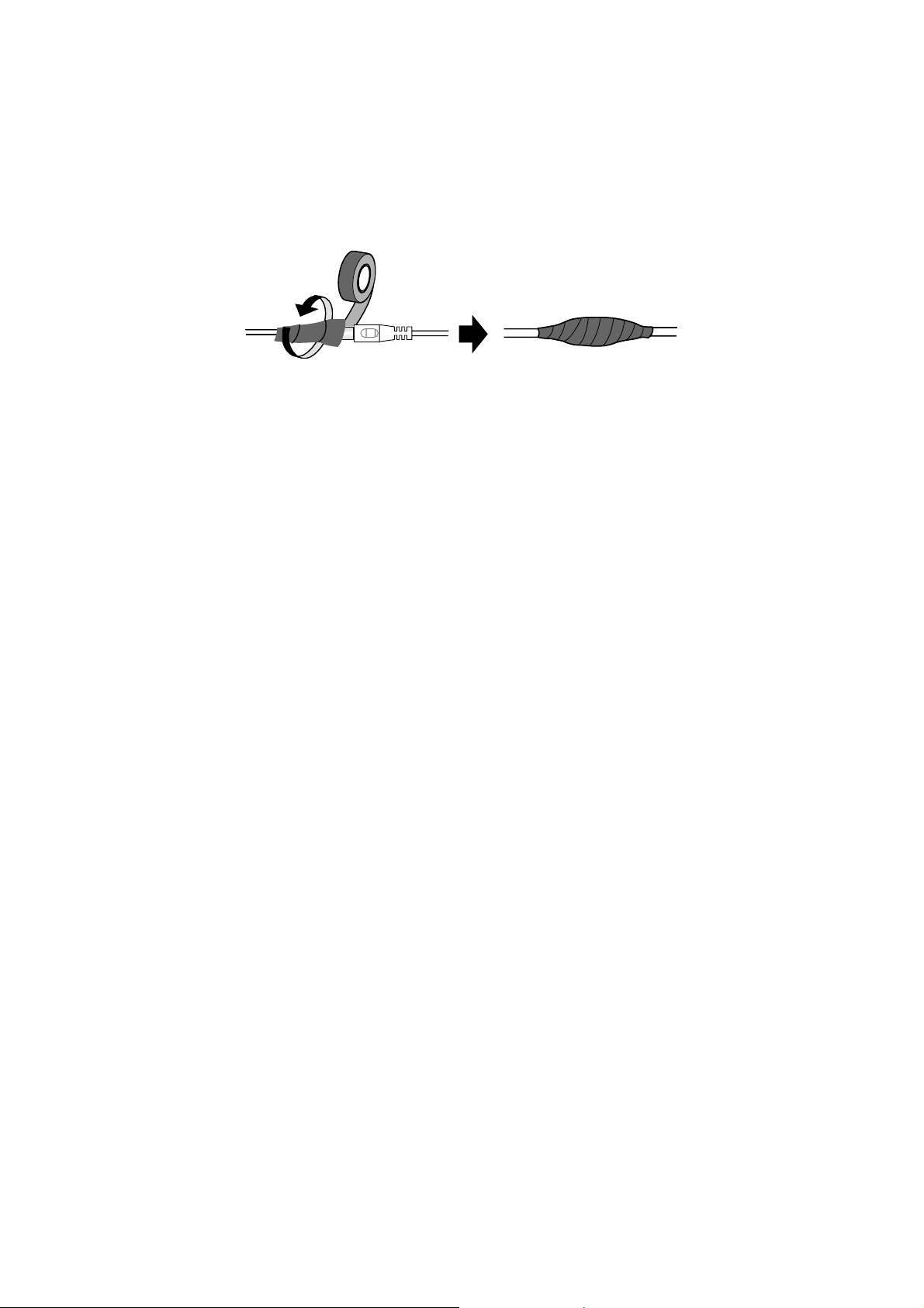
When installing the GV-IP Speed Dome, be sure that any PoE, power, audio and I/O cables
are waterproofed using waterproof silicon rubber or the like.
ix
Page 11
Optional Devices
Optional devices can expand your camera’s capabilities and versatility. Contact your dealer
for more information.
Device Description
The GV-Mount Accessories provide a comprehensive
lineup of accessories for installing the outdoor GV-IP
GV-Mount Accessories
In-Ceiling Installation
Package
Power Adapter
PA-901 PoE Adapter The GV-PA901 is a Power over Ethernet (PoE) adapter
GV-PoE Switch The GV-PoE Switch is designed to provide power along
Speed Dome on ceiling, wall corner and pole. For details,
see GV-Mount Accessories Installation Guide on the
Software CD.
The in-ceiling package is used to install the indoor GV-IP
Speed Dome by embedding the camera to the ceiling.
The 24V DC power adapter is designed to convert AC 100V
~ 240V 2.5A to DC 24V 3.75A and supply the power to
indoor and outdoor GV-IP Speed Dome. The power
adapter is available in the regions: AR, AU, EU, JU, UK,
US.
designed to provide power and network connection through
a single Ethernet cable to outdoor GV-IP Speed Dome.
with network connection for IP devices. The GV-PoE
Switch is available in various models with different numbers
and types of ports.
x
Page 12

Introduction 1
Chapter 1 Introduction
1.1 Overview
The GV-IP Speed Dome is a network PTZ camera designed for image quality and adaptability
in various environments. This camera offers the image of 1080p at 30 fps, 720p at 60 fps and
20x / 30x optical zoom, capable of showing smooth live view with great detail. In low-light
environments, image quality is promised with its image processing tools, such as IR cut filter
(ICR), Wide Dynamic Range pro (WDR pro), Backlight Compensation and noise reduction.
Wide surveillance coverage is made possible with 360° endless panning and 180° tilting
capacity. With GV-SD2301, it is up to 200° tilting angle. Dome movements such as Preset,
Sequence, Auto Pan, Cruise and Tour can be programmed and activated by schedule. You
can create multiple dome movement modes and have different modes enabled at different
time slots. The GV-IP Speed Dome provides variable pan/tilt speeds ranging from a fast patrol
of 400°/460° per second to a slow ramble of 0.5° per second with 0.2° pan accuracy for fast
and accurate tracking ability.
GeoVision offers a complete series of GV-IP Speed Dome comes for indoor and outdoor use,
and also optional mounting kits for outdoor installations on wall, ceiling and pole.
1
Page 13

Features:
• 1/2.8’’ progressive scan CMOS sensor
• Full HD 1080p at up to 30 fps and 720p at up to 60 fps
• 20x / 30x optical zoom and 12x digital zoom
• Wide Dynamic Range Pro (WDR Pro)
• Day and night function with IR-cut filter
• 2-way audio
• Vandal resistance (IK10 for metal and polycarbonate casing, GV-SD220-S / GV-SD2300
/ GV-SD2301 only)
• Ingress protection (IP67 for GV-SD220-S / GV-SD2300 / GV-SD2301 only)
• Built-in SD card slot for local storage
• 4 digital inputs, 1 relay output
• DC 24V / AC 24V / PoE + (IEEE 802.3at) for GV-SD220, PoE ++ (60 W) for GV-SD220-S
/ GV-SD2300 and PoE ++ (50 W) for GV-SD2301
• Pan 360° endlessly
• Tilt from 0° to 180° for GV-SD220 / GV-SD220-S / GV-SD2300 and -20° to 220° for
GV-SD2301
• Preset speed at up to 400°/sec for GV-SD220 and 460°/sec for GV-SD220-S / GV-2300 /
GV-2301
• PTZ movement (Preset, Sequence, Auto Pan, Cruise and Tour)
• PTZ movement by schedule
• Auto and manual PTZ calibration
• Auto focus
• Backlight Compensation
• Image noise reduction
• Motion detection
• Privacy Mask
• Dual streams H.264 and MJEPG
• Smart phones & 3GPP support
• 31 languages on Web interface
• ONVIF (Profile S) conformant
2
Page 14

Introduction 1
1.2 System Requirements
To access GV-IP Speed Dome functions through Web browser, ensure your PC is in good
network connection and use one of the following web browsers:
• Microsoft Internet Explorer 7.x or later
• Google Chrome
• Mozilla Firefox
• Safari
Note:
1. For users of Internet Explorer 8, additional settings are required. For details, see
Appendix C.
2. With non-IE browsers,
A. Motion Detection, Text Overlay, two-way audio settings are not supported.
B. The Play function is only available on the live view window (Figure 3-2)
C. RTSP streaming must be kept as enabled. For more details, see 5.3.8 RTSP /
3GPP.
3
Page 15
1.3 Packing List
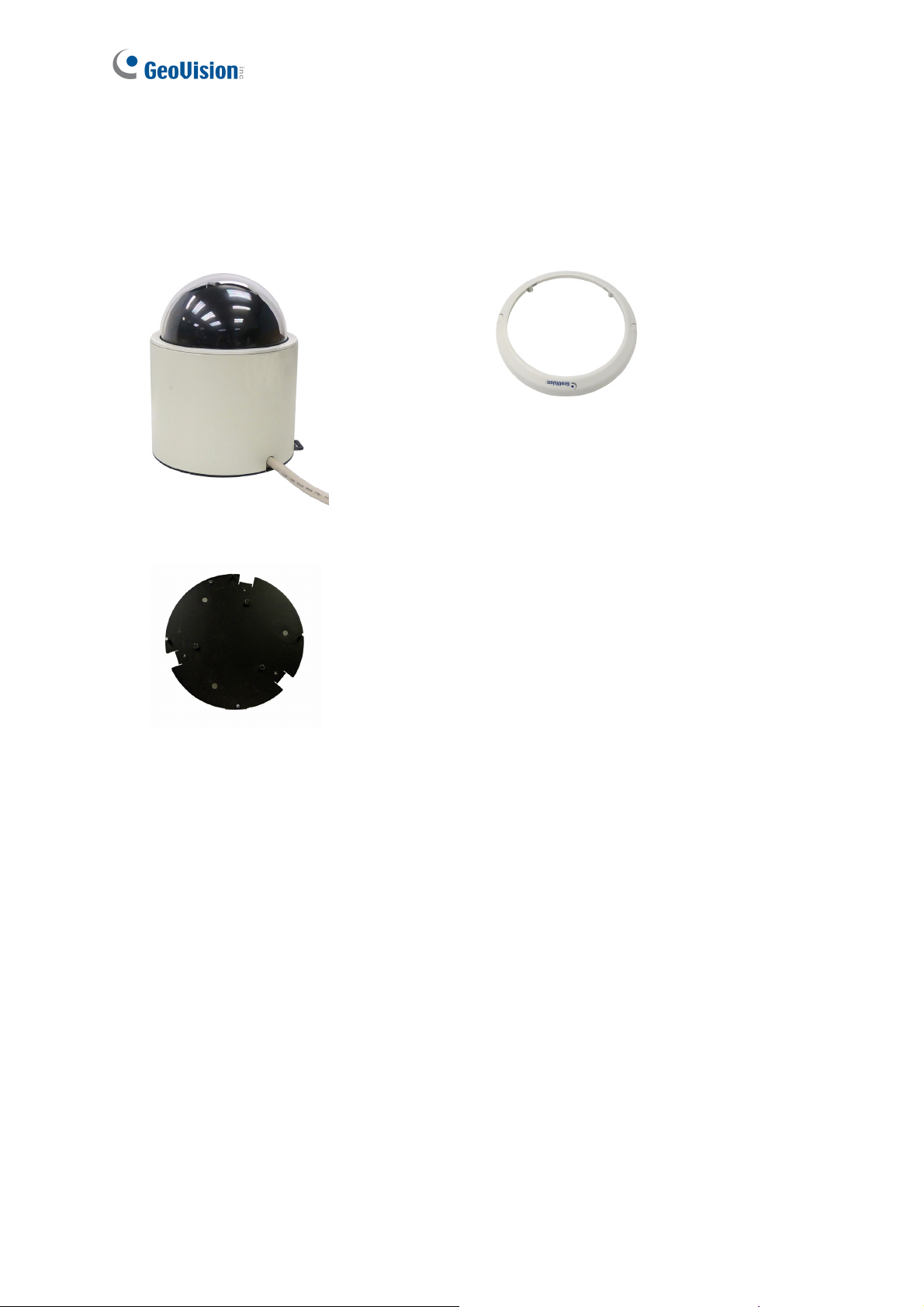
1.3.1 Indoor GV-IP Speed Dome Camera (GV-SD220)
• Indoor GV-IP Speed Dome
• Mounting Plate
• Hard-Ceiling Cover
• GV-IP Speed Dome Software CD
• GV-NVR Software DVD
4
Page 16
Introduction 1
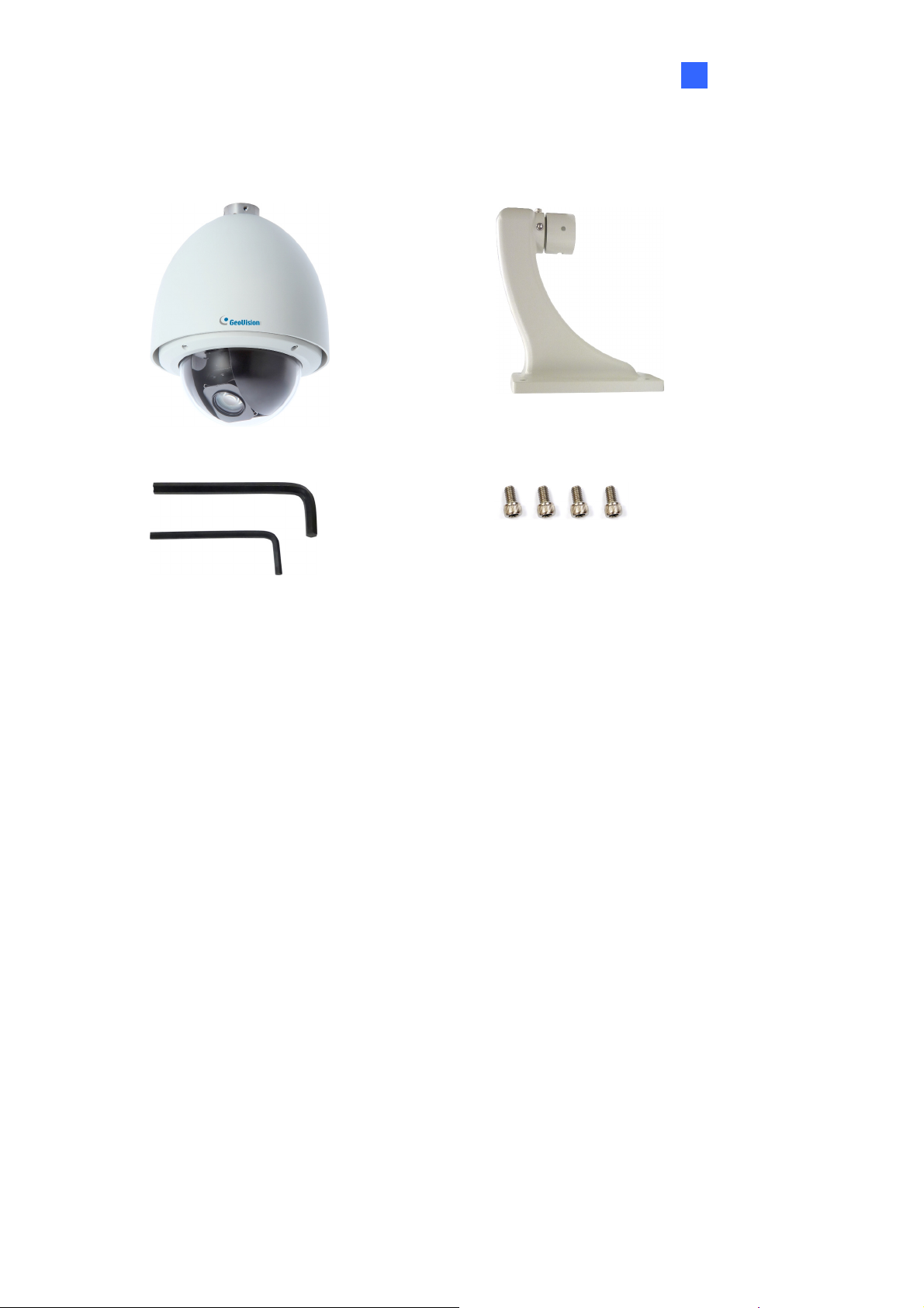
1.3.2 Outdoor GV-IP Speed Dome Camera (GV-SD220-S / GV-SD2300)
• Outdoor GV-IP Speed Dome
• Hex Key x 2
• Desiccant Pack x 4 • GV-IP Speed Dome Software CD
• Pendant Tube
• M6 Screw x 4
• GV-NVR Software DVD
5
Page 17
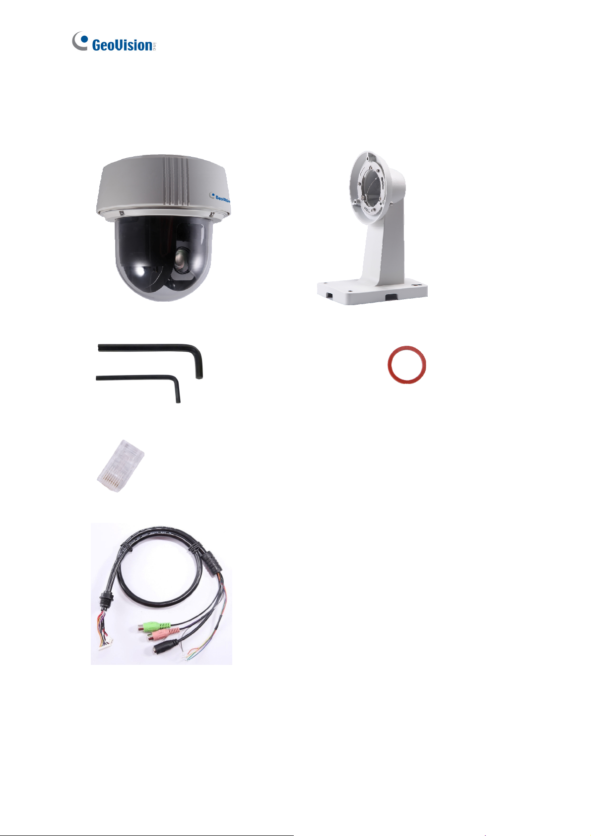
1.3.3 Outdoor GV-IP Speed Dome Camera (GV-SD2301)
• Outdoor GV-IP Speed Dome
• Hex Key x 2
• Pendant Tube
• Rubber ring
• RJ-45 Connector
• Data Cable
• GV-NVR Software DVD
• Desiccant Pack x 2
• GV-IP Speed Dome Software CD
6
Page 18
Introduction 1
1.4 Functional Panel
To access the functional panel of the GV-IP Speed Dome follow the section below to remove
its camera cover first.
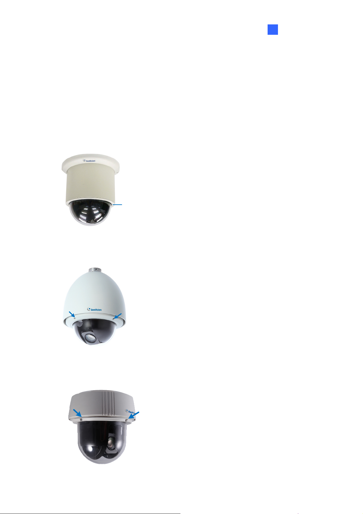
1.4.1 Removing the Camera Cover
• GV-SD220: Rotate to remove the camera cover.
camera cover
Figure 1-1
• GV-SD220S / GV-SD2300: Unscrew using the supplied hex key.
Figure 1-2
• GV-SD2300: Unscrew using the supplied hex key.
Figure 1-3
7
Page 19
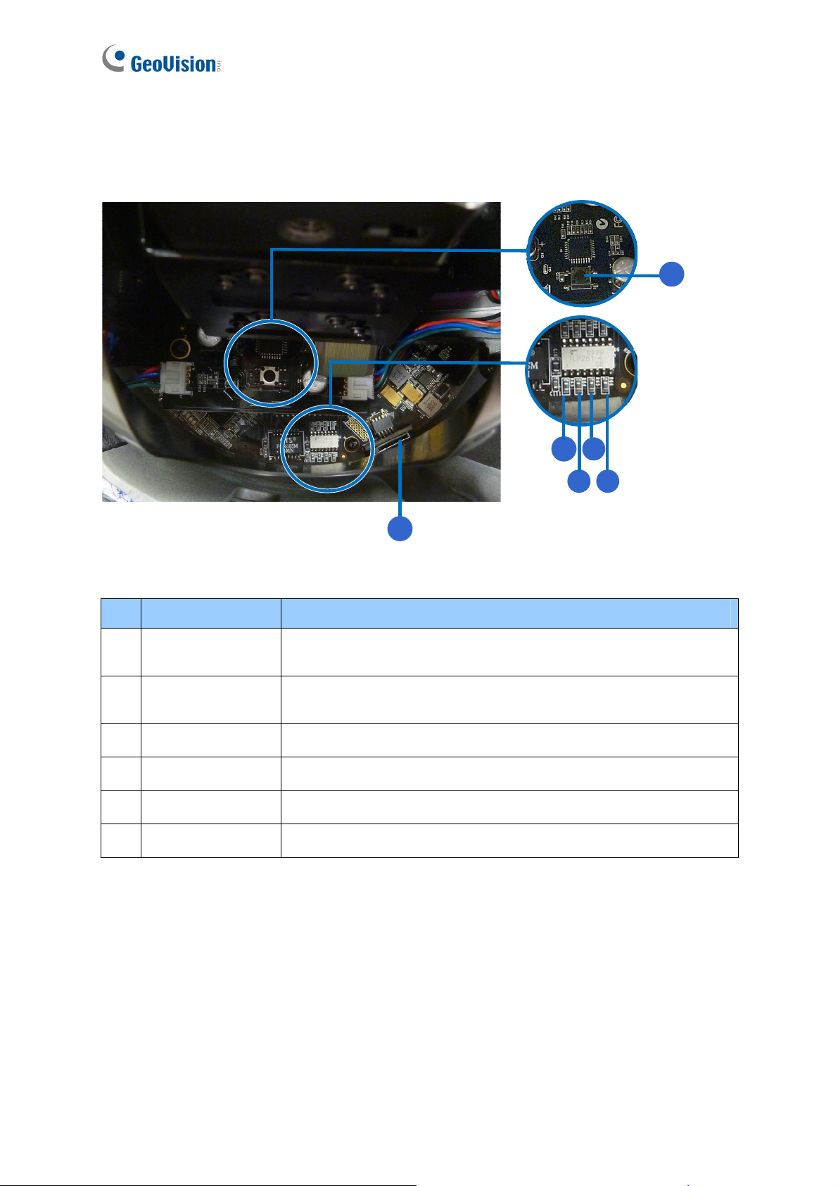
1.4.2 Camera Interior
1.4.2.1 GV-SD220/ GV-SD220S / GV-SD2300
1
234
5
6
Figure 1-4
No. Name Function
1. Default
2. Status
3. Power The power LED turns green when the power is on.
4. ACT The ACT LED flashes orange light upon data transmission.
5. Link The Link LED turns green with Internet connectivity.
6. Memory Card Slot Insert a micro SD / SDHC card to store recording data.
Restores all the settings to the factory default values. For details
see 7.3 Restoring to Factory Default Settings.
The status LED turns green when the power is on and fades
when the camera is ready for use.
8
Page 20
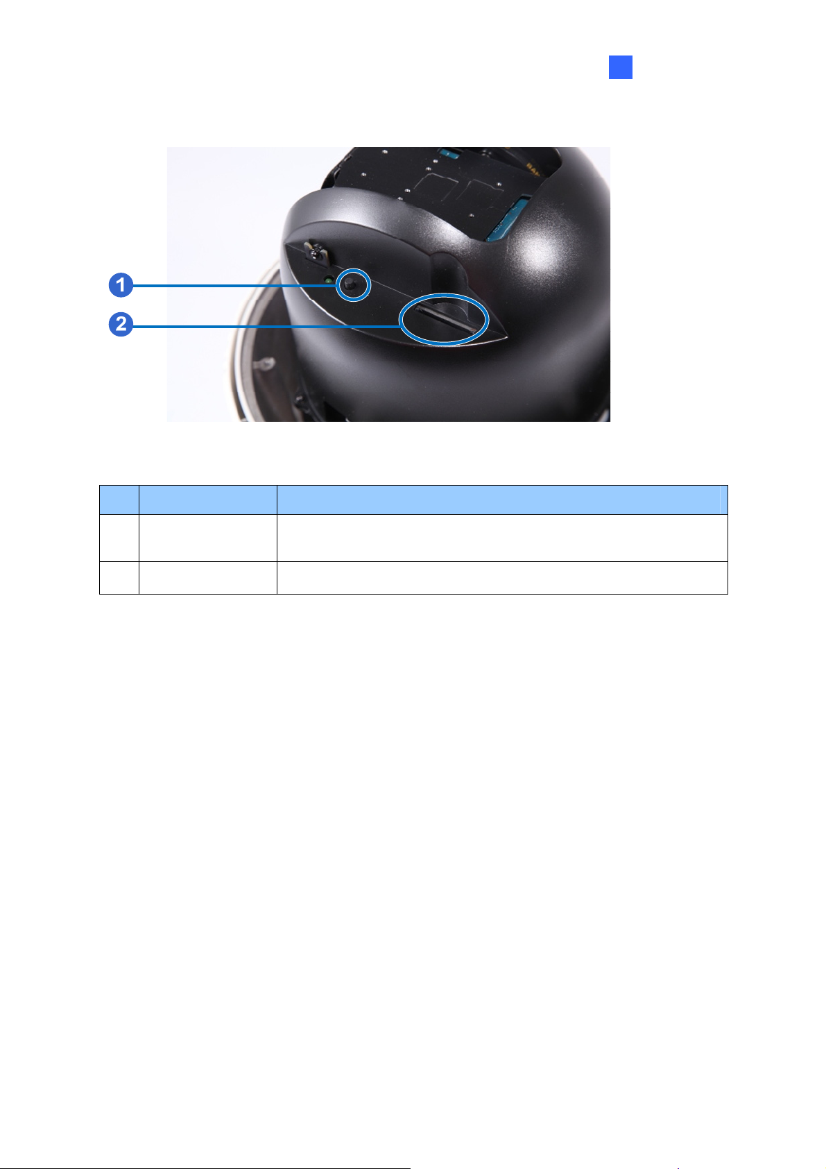
1.4.2.2 GV-SD2301
Figure 1-5
Introduction
1
No. Name Function
1. Default
Restores all the settings to the factory default values. For details
see 7.3 Restoring to Factory Default Settings.
2. Memory Card Slot Insert a SD / SDHC card to store recording data.
9
Page 21
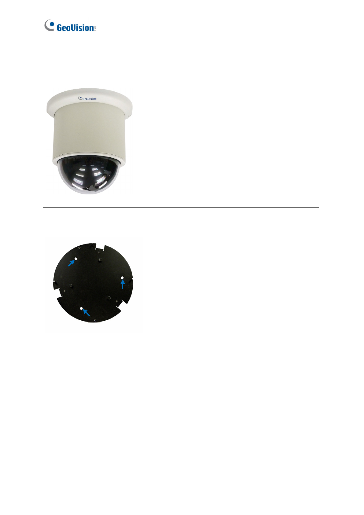
1.5 Installing the GV-IP Speed Dome
1.5.1 Indoor GV-IP Speed Dome: Hard-Ceiling Mount
Required Items
• Indoor packing (supplied)
• ceiling screws x 3 (user-prepared)
Figure 1-6
1. Secure the mounting plate to the ceiling with self-prepared screws.
Figure 1-7
10
Page 22
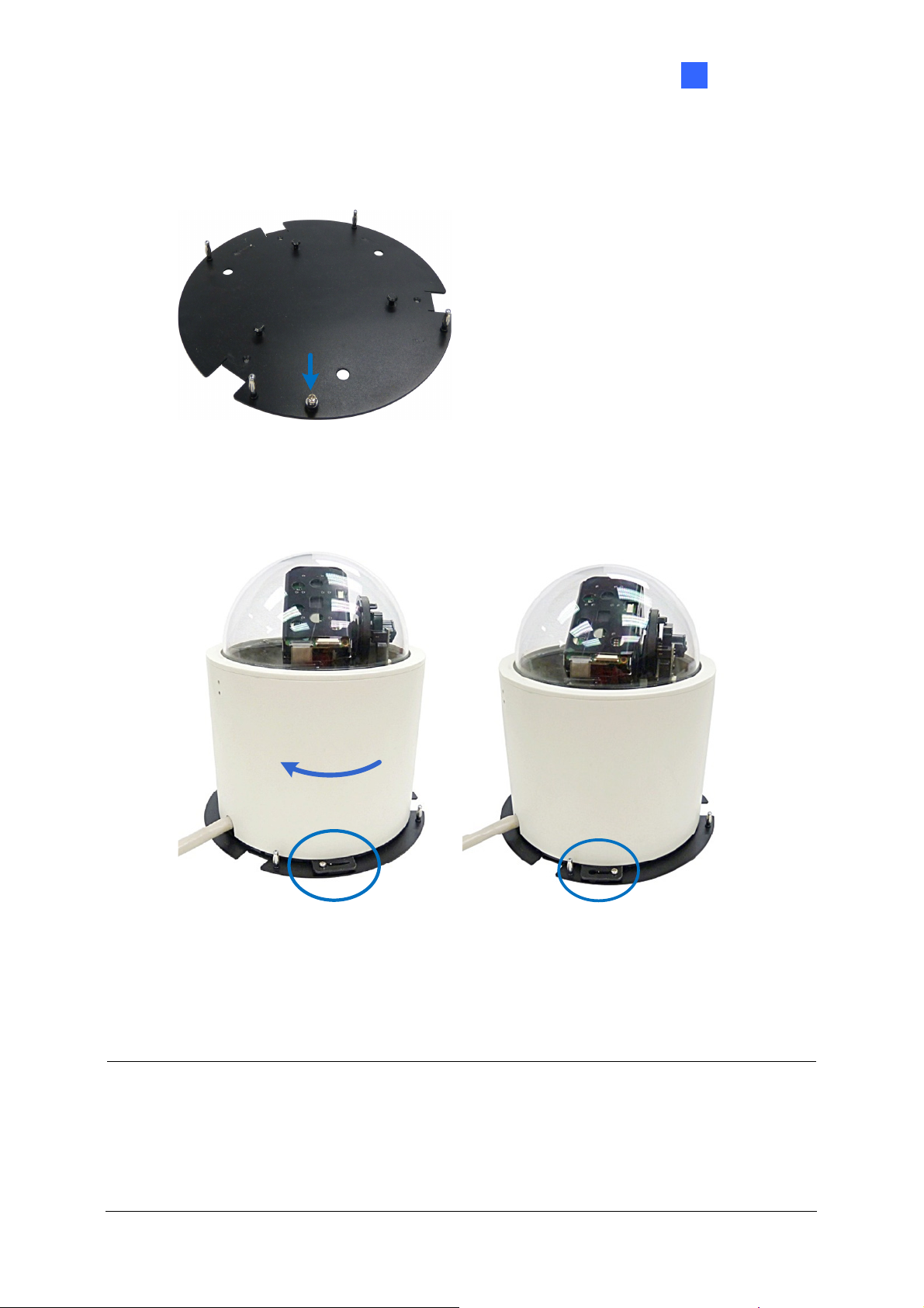
2. Secure the indoor GV-IP Speed Dome to the mounting plate.
A. Loosen the screw on the mounting plate
Figure 1-8
B. Align the camera to the mounting plate and rotate the camera body to the right.
Introduction 1
Figure 1-9
C. Tighten the screw.
3. Put on the hard-ceiling cover.
Note:
1. Cut away a side of the cover if you want to run the cable through.
2. You may also install the indoor GV-IP Speed Dome into the ceiling with optional
mounting kits. For detail, see GV-Mount Accessories Installation Guide on the Software
CD.
11
Page 23
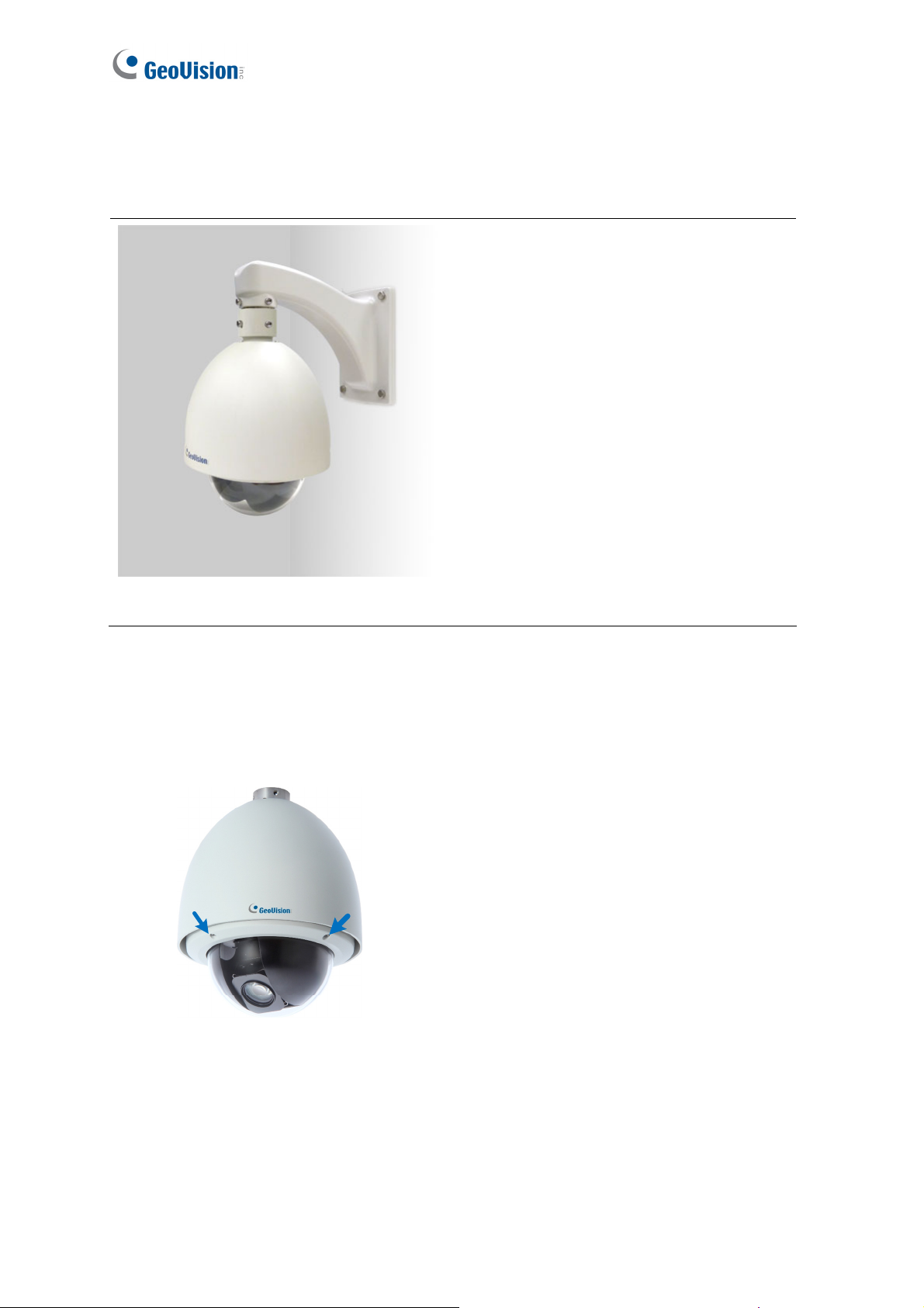
1.5.2 Outdoor GV-IP Speed Dome: Wall Pendant Mount
1.5.2.1 GV-SD220-S / GV-SD2300
Required Items
• Outdoor packing (supplied)
• Ceiling screws x 4 (user-prepared)
Figure 1-10
1. Insert the desiccants to the camera.
A. Remove the camera cover using the supplied hex key.
Figure 1-11
12
Page 24
Introduction 1
B. Insert two desiccant packs to the indicated places.
Figure 1-12
IMPORTANT: Be sure to conceal the desiccants in the GV-IP Speed Dome within 2 minutes
of opening the desiccant pack.
C. Insert your micro SD card into the memory card slot. See 1.4.2.1 GV-SD220/
GV-SD220S / GV-SD2300
D. Follow step 1A to secure the camera cover with the supplied hex key.
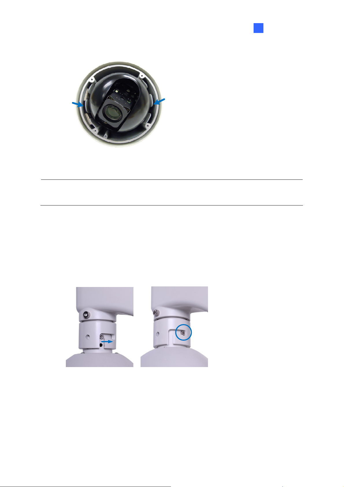
2. Assemble the camera with the pendant tube.
A. Thread the camera cable through the pendant tube.
B. Rotate the camera and lock it to the pendant tube.
Figure 1-13
13
Page 25
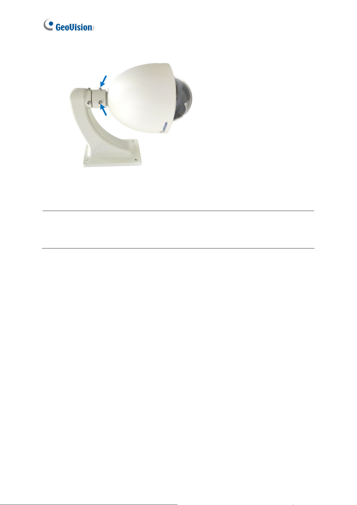
C. Secure the camera with the supplied M6 screws.
Figure 1-14
3. Secure the pendant tube to the wall with self-prepared screws.
Note: You may also install the camera to ceilings, wall corners (concave or convex), and
poles using optional mounting kits. For details, see GV-Mount Accessories Installation
Guide on the Software CD.
14
Page 26
1.5.2.2 GV-SD2301
Introduction 1
Required Items
• Outdoor packing (supplied)
• Ceiling screws x 4
(user-prepared)
Figure 1-15
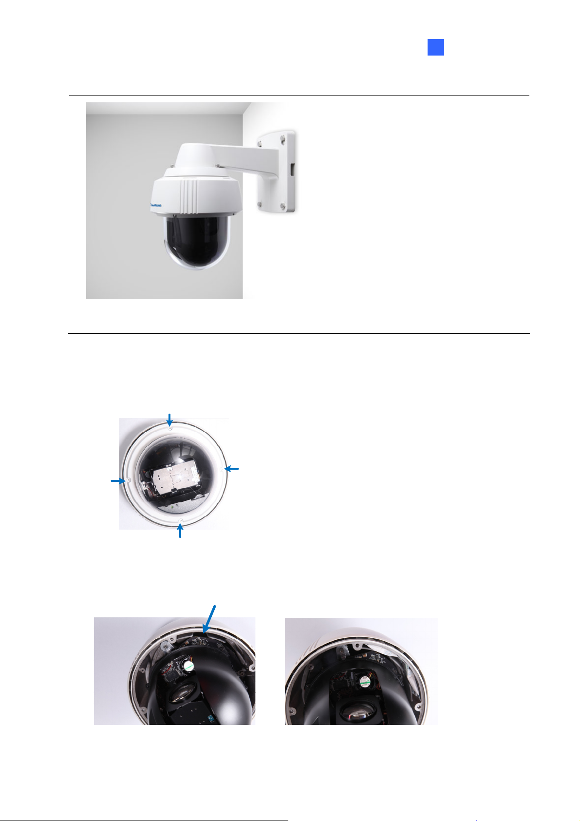
1. Insert the desiccants to the camera.
A. Remove the camera cover using the supplied hex key.
Figure 1-16
B. Insert one desiccant pack to the indicated place.
Figure 1-17
15
Page 27
IMPORTANT: Be sure to conceal the desiccants in the GV-SD2301 within 2 minutes of
opening the desiccant pack.
C. Insert your SD card into the SD card slot. See 1.4.2.2 GV-SD2301.
D. Secure the camera cover with the supplied hex key.
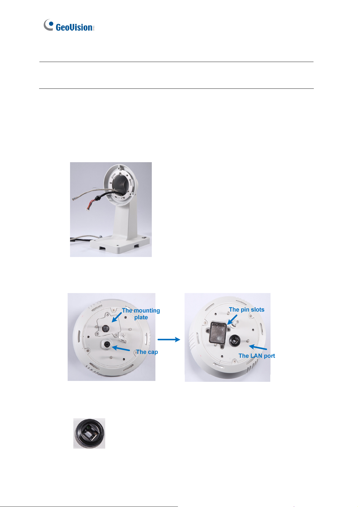
2. Connect the cables to the camera.
A. Thread the Ethernet cable and the data cable through the pendant tube.
Figure 1-18
B. Remove the cap and the mounting plate at the back of the camera.
Figure 1-19
C. Insert the Ethernet cable to the LAN port on the camera.
16
Figure 1-20
Page 28
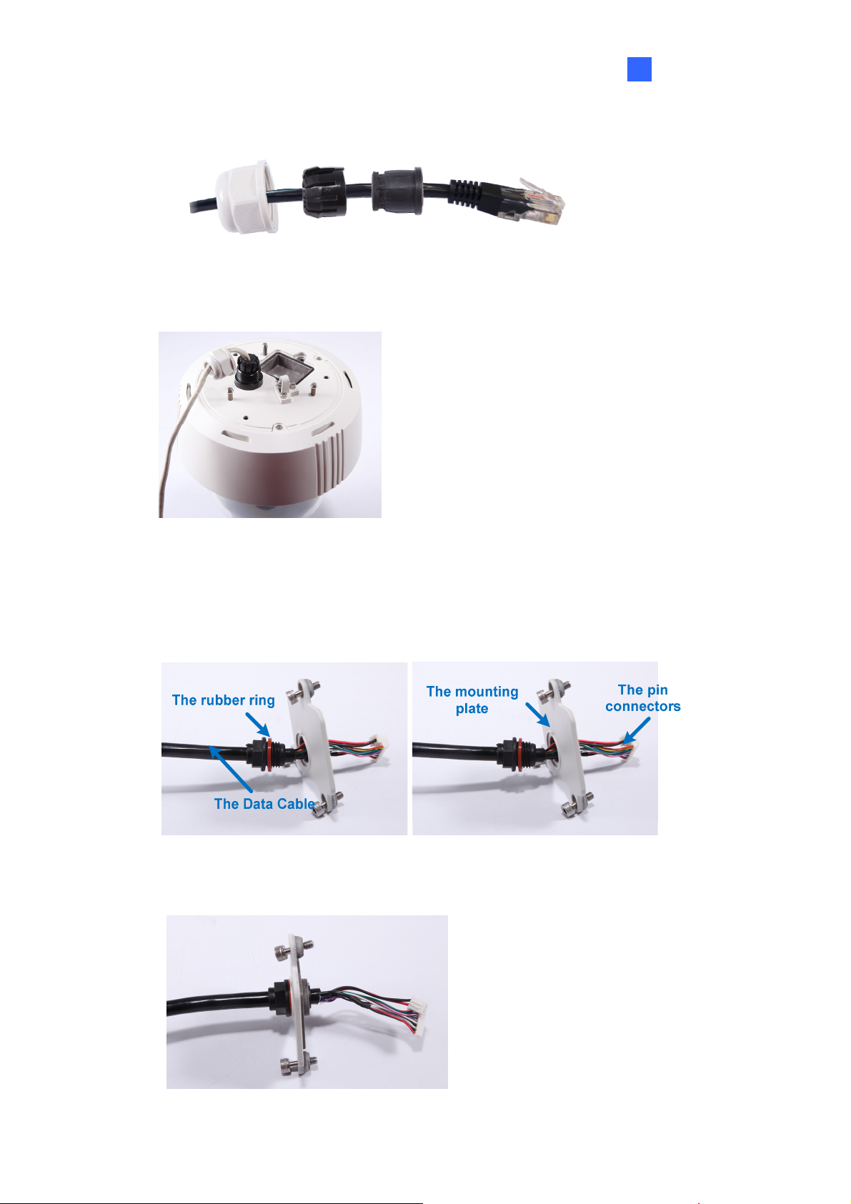
D. Slide the cap and components through the Ethernet cable as shown below.
Introduction 1
Figure 1-21
E. Move the cap and the components toward the LAN port.
Figure 1-22
F. Secure the cap tightly.
G. Slip the rubber ring on the Data Cable and then pass the pin connectors of the Data
Cable through the mounting plate.
Figure 1-23
H. Fasten the data cable with the mounting plate and the rubber ring.
Figure 1-24
17
Page 29
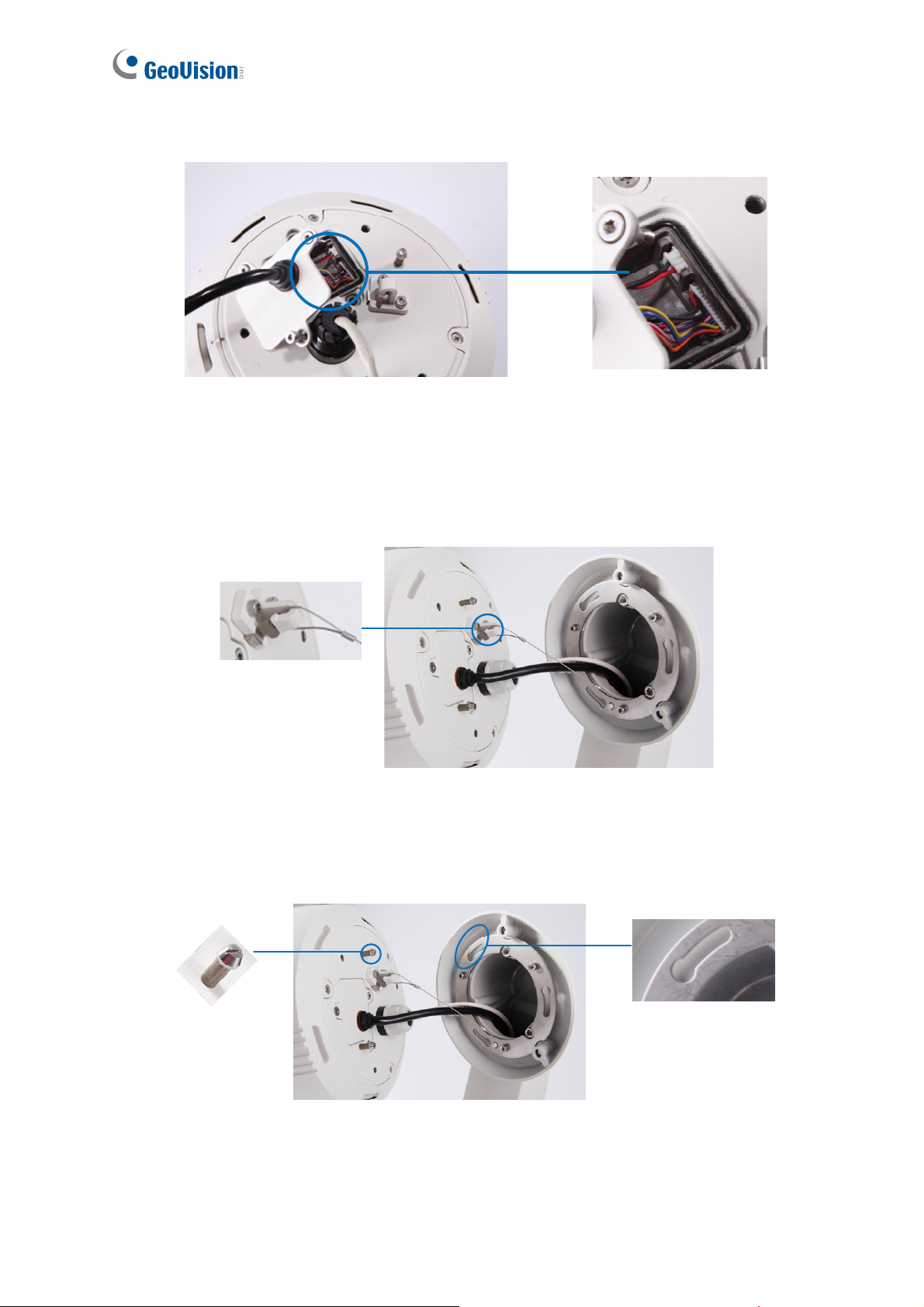
I. Insert the pin connectors of the Data Cable to the indicated area.
Figure 1-25
J. Secure the mounting plate with the supplied hex key.
3. Assemble the camera with the pendant tube.
A. Secure the safety lock.
Figure 1-26
B. Push the rivets into the holes on the pendant tube and rotate clockwise to lock the
position.
Figure 1-27
18
Page 30
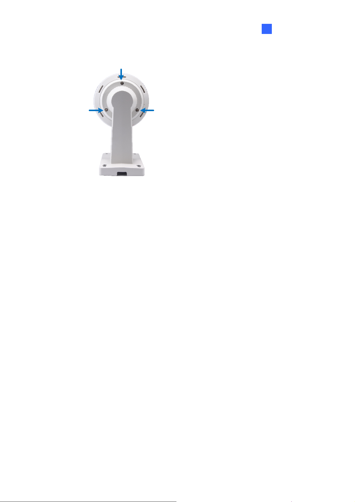
C. Tighten the screws with the supplied hex key.
Introduction 1
Figure 1-28
D. Secure the pendant tube to the wall with self-prepared screws.
19
Page 31

1.6 Connecting the Camera
Follow the steps below to connect the camera. Refer to The Data Cable and I/O Wire
Definition in this section for detailed information.
1. Connect Power using one of the following methods:
• Connect the Power Adapter to the camera. See The Data Cable section below for how
to connect the Power Adapter to the data cable.
• Use the Power over Ethernet (PoE) function and the power will be provided over the
network cable.
2. Connect a standard network cable to the Ethernet cable of the camera.
3. Optionally connect I/O devices, speaker and microphone to the camera.
For how to use the PoE function on the Outdoor GV-IP Speed Dome, see 16.1 Connecting
the GV-PA901 PoE Adapter.
Note:
1. The Power Adapter is an optional device.
2. The Optional GV-PA901 PoE Adapter is required for applying PoE function.
20
Page 32

Introduction 1
The Data Cable
With the Data Cable, you can connect the power, microphone, speaker, and I/O devices to the
GV-IP Speed Dome. The Data Cable is illustrated as below.
I/O Wires
Microphone
Speaker
Ethernet
Power Adapter
Figure 1-13
I/O Wire Definition
The I/O wires on the Data Cable allow you to connect 4 alarm input and 1 output devices.
Connect the I/O devices based on the wire definition listed below.
No. Wire Definition
1 Orange Alarm In 1
2 Yellow Alarm In 2
3 Green Alarm In 3
4 Blue Alarm In 4
5 Pink Ground
6 Purple Alarm Out
7 White Alarm Out_Open
8 Gray Alarm Out_Close
21
Page 33

1.6.1 Connecting the GV-PA901 PoE Adapter
The GV-PA901 PoE Adapter is only for the Outdoor GV-IP Speed Dome. Prepare two
Ethernet cables for the connection.
Note: PoE function is available for the Outdoor GV-IP Speed Dome only when GV-PA901
PoE Adapter (optional device) is applied for connection.
1. Connect one end of an Ethernet cable to the LAN 10 / 100 Port on the GV-PA901 and the
other end to the LAN port on a Hub / Router.
2. Connect one end of an Ethernet cable to the PoE 10 / 100 port on the GV-PA901, and the
other end to the Outdoor GV-IP Speed Dome.
3. Connect the connector end of the GV-PA901 Power Adapter to the GV-PA901 PoE
Adapter and the plug end to the power outlet.
22
Figure 1-14
Page 34

Getting Started 2
Chapter 2 Getting Started
2.1 Looking Up the IP Address
By default, your GV-IP Speed Dome is assigned with an unused IP address by the DHCP
server when the camera is connected to the network. This IP address remains unchanged
unless you unplug or disconnect your camera from the network.
Note: If your router does not support DHCP, the default IP address will be 192.168.0.10. In
this case, it is strongly suggested to modify the IP address to avoid IP address conflict with
other GeoVision IP device on the same LAN. To change the IP address, see Changing the IP
Address later in this section.
Follow the steps below to check out the GV-IP Speed Dome’s IP address:
1. Install the GV-IP Device Utility program from the Software CD.
Note: The PC installed with GV-IP Device Utility must be under the same LAN with the
camera you wish to configure.
2. On the PC desktop, select Start, point to Programs and select GV IP Device Utility to
execute the program. The GV IP Device Utility window appears and automatically
searches for the GV IP devices on the same LAN.
Figure 2-1
23
Page 35

3. Click the Name or Mac Address column to sort.
Figure 2-2
4. Find the Mac Address of the camera to see its IP address.
Changing the IP Address
To modify the static IP address or set the camera to a public dynamic IP address, log in the
Web interface to access the network setting page.
1. Open your web browser, and type in the IP address.
• For static network connection, type the default IP address http://192.168.0.10
• For DHCP connection, follow steps in 2.1 Looking Up the IP Address to look up the
current IP address.
2. In both Login and Password fields, type the default value admin. Click Apply.
3. In the left menu, select Network and then LAN to begin the network settings. This page
appears.
24
Figure 2-3
Page 36

Getting Started 2
4. Select Dynamic IP address, Static IP address or PPPoE and type the required network
information.
5. Click Apply. The camera is now accessible by entering the assigned IP address on the
web browser.
Important:
1. If your camera uses a public dynamic IP address via PPPoE, use the dynamic DNS
Service to obtain a domain name linked to the camera’s changing IP address first. For
details on Dynamic IP Address and PPPoE, see 5.7.2 Advanced TCP/IP and 5.7.1 LAN
Configuration.
2. If Dynamic IP Address or PPPoE is enabled and you cannot access the camera, you
may have to reset it to the factory default and then perform the network settings again.
To restore the factory settings, see 6.3 Restoring to Factory Default Settings.
25
Page 37

2.2 Accessing Your Surveillance Images
Follow these steps to access your surveillance images:
1. Open the Internet Explorer browser.
2. Enter the IP address or domain name of the GV-IP Speed Dome in the Location/Address
field of your browser. To look up the IP address, see 2.1 Looking Up the IP Address.
Figure 2-4
3. Enter the login name and password. The administrator account has unrestricted access to
all the features and function. The guest account is restricted to accessing live view and
network status information.
• The default login name and password for Administrator are admin.
• The default login name and password for Guest are guest.
4. A video image, similar to the example in Figure 3-1, is now displayed on your browser.
Note: To enable the updating of images in Microsoft Internet Explorer, you must set your
browser to allow ActiveX Controls and perform a once-only installation of GeoVision’s
ActiveX component onto your computer.
26
Page 38

Getting Started
2
2.3 Configuring the Basics
Once you have installed and logged in the GV-IP Speed Dome, you are ready to configure
some of its primary settings through the Web interface:
• Date and time adjustment: see 5.8.1 Date & Time Settings.
• Login and privileged passwords: see 5.8.4 User Account.
• Network gateway: see 5.7 Network.
• Camera image adjustment: see 3.2 The Control Panel of the Live View Window.
• Video format, signal format, resolution and frame rate: see 5.1.1 Video Settings.
IMPORTANT: If you are using a 50 Hz flicker, set the Flicker Hz value to 50 Hz. See Video
Signal Type in 5.1.1 Video Settings.
27
Page 39

Chapter 3 Guest Mode and Live View Panel
This section introduces the features of the guest mode and the live view window.
Main Page of Guest Mode
28
Figure 3-1
Page 40

3
Guest Mode & Live View Panel
3.1 The Live View Window
In the left menu, click Live View, and then select Camera to see the live video.
12
11
10
1
2
3 4
Figure 3-2
No. Name Function
1 Play Plays live video.
2 Stop Stops playing video.
3 Microphone Talks to the surveillance area from the local computer.
4 Speaker Listens to the audio around the camera.
5 Snapshot
6 File Save
7 Full Screen
Takes a snapshot of live video.
--- See 3.3 Snapshot of a Live Video.
Records live video to the local computer.
--- See 3.4 Video Recording.
Switches to full screen view. Right-click the image to have these
options: Snapshot, Full Screen, Resolution, PIP, PAP,.
--- See 3.5 Picture-in-Picture and Picture-and-Picture View.
5 6
9
8
7
29
Page 41

No. Name Function
Clicks to switch to one of the three visual PTZ control modes:
8 Visual PTZ
9 PTZ Home
10 I/O Control
11 PTZ Control
Show System
12
Menu
Fixed Direction Move, Random Move or Center Move. For
details, see 3.12 Visual PTZ.
Click to return the dome view to the home position. To set up a
home position, see 4.12 PTZ Settings-Other.
Starts the I/O Control Panel.
--- See 3.13 I/O Control.
Starts the PTZ Control Panel and the Visual PTZ.
--- See 3.11 PTZ Control and 3.12 Visual PTZ.
Brings up these functions: Alarm Notify, Video and Audio
Configuration, Remote Config, Show Camera Name and
Image Enhance.
--- See 3.6 Alarm Notification, 3.7 Video and Audio Configuration,
3.8 Remote Configuration, 3.9 Camera Name Display and 3.10
Image Enhancement respectively.
30
Page 42

3
Guest Mode & Live View Panel
3.2 The Control Panel of the Live View Window
To open the control panel of the Live View window, click the arrow button on top of the viewer.
You can access the following functions by using the right and left arrow buttons on the control
panel.
Click the this arrow button
to open the control panel
Left arrow
button
Right arrow
button
Figure 3-3
[Information] Displays the version of the GV-IP Speed Dome, local time of the local computer,
host time of the GV-IP Speed Dome, the number of users logging in to the GV-IP Speed Dome
and the OCX registration path.
[Video] Displays the current video codec, resolution and data rate.
[Audio] Displays the audio data rates when the microphone and speaker devices are
enabled.
[I/O Control] Provides a real-time graphic display of the input and output status. You can
force the output to be triggered by double-clicking its icon.
[Alarm Notify] Displays the captured images by sensor triggers and/or motion detection. For
this function to work, you must configure the Alarm Notify settings first. See 3.7 Alarm
Notification.
[Internal Temperature] Shows the current internal temperature of the camera and the normal
temperature range.
[Download] Allows you to install programs from the hard drive.
31
Page 43

3.3 Snapshot of a Live Video
To take a snapshot of live video, follow these steps:
1. Click the Snapshot button (No. 5, Figure 3-2). The Save As dialog box appears.
2. Specify Save in, type the File name, and select JPEG or BMP for Save as Type. You
may also choose to display the camera name and/or the date, the text color and image
quality for the snapshot.
3. Click the Save button to save the image in the local computer.
Note: You can also obtain a snapshot of the live view without logging in the user interface by
executing the CGI command. See Appendix A.
3.4 Video Recording
You can record live video for a certain period of time to your local computer.
1. Click the File Save button (No. 6, Figure 3-2). The Save As dialog box appears.
2. Specify Save in, type the File name, and move the Time Period scroll bar to specify the
time length of the video clip from 1 to 5 minutes.
3. Click the Save button to start recording.
4. To stop recording, click the Stop button (No. 2, Figure 3-2).
32
Page 44

3
Guest Mode & Live View Panel
3.5 Picture-in-Picture and Picture-and-Picture View
The full screen mode provides two types of close-up views: Picture-in-Picture (PIP) and
Picture-and Picture (PAP). The two views are useful to provide clear and detailed images of
the surveillance area.
Picture-in-Picture View
With the Picture-in-Picture (PIP) view, you can crop the video to get a close-up view or zoom
in on the video.
Navigation box
Inset window
Figure 3-4
1. Right-click the live view and select PIP. An inset window appears.
2. Click the insert window. A navigation box appears.
3. Move the navigation box around in the inset window to have a close-up view of the
selected area.
4. To adjust the navigation box size, move the cursor to any of the box corners, and enlarge
or diminish the box.
5. To exit the PIP view, right-click the image and click PIP again.
33
Page 45

Picture-and-Picture View
With the Picture-and-Picture (PAP) view, you can create a split video effect with multiple
close-up views on the image. A total of 7 close-up views can be defined.
Figure 3-5
1. Right-click the live view and select PAP. A row of three inset windows appears at the
bottom.
2. Draw a navigation box on the image, and this selected area is immediately reflected in
one inset window. Up to seven navigation boxes can be drawn on the image.
3. To adjust a navigation box size, move the cursor to any of the box corners, and enlarge or
diminish the box.
4. To move a navigation box to another area on the image, drag it to that area.
5. To add, display/hide or to change the frame color of the navigation boxes, right-click the
live view, select Mega Pixel Setting and click one of these options:
Enable Add-Focus-Area Mode: Allows the user to add navigation boxes to the
image.
Display Focus Area of PAP Mode: Displays or hides the navigation boxes on the
image
Set Color of Focus Area: Changes the color of the box frames.
6. To delete a navigation box, right-click the desired box, select Focus Area of PAP Mode
and click Delete.
7. To exit the PAP view, right-click the image and click PAP again.
34
Page 46

3
Guest Mode & Live View Panel
3.6 Alarm Notification
After input triggers and motion detection, you can be alerted by a pop-up live video and view
up to four captured images.
Pop-up live video
Captured images
Figure 3-6
To configure this function, click the Show System Menu button (No. 12, Figure 3-2), and
select Alarm Notify. This dialog box appears.
Figure 3-7
Motion Notify: Once motion is detected, the captured images are displayed on the
control panel of the Live View window.
I/O Alarm Notify: Once the input device is triggered, the captured images are displayed
on the control panel of the Live View window. For this function to work, the Administrator
needs to install the input device properly. See 5.2.1 Input/Output Settings.
Alert Sound: Activates the computer alarm on motion and input-triggered detection.
Auto Snapshot: The snapshot of live video is taken every 5 seconds on motion and
input-triggered detection.
File Path: Assigns a file path to save the snapshots.
35
Page 47

3.7 Video and Audio Configuration
You can enable the microphone and speaker for two-way audio communication and adjust the
set the number of frames to keep for live view buffer.
Click the Show System Menu button (No. 12, Figure 3-2), and select Video and Audio
Configuration.
Camera: Sets the number of frames to keep in live view buffer. Keeping more frames for
live view buffer can ensure a smooth live view, but the live view will be delayed for the
number of seconds specified.
Figure 3-8
Audio Configure: You can enable the microphone and speaker and adjust the audio
volume.
36
Figure 3-9
Page 48

3
Guest Mode & Live View Panel
3.8 Remote Configuration
You can upgrade the device firmware over the network. Click the Show System Menu button
(No. 12, Figure 3-2), and select Remote Config. The Remote Config dialog box will appear.
[Firmware Upgrade] In this tab, you can upgrade the firmware over the network. For details,
see Chapter 6 Advanced Applications.
3.9 Camera Name Display
To display the camera name on the image, click the Show System Menu button (No. 12,
Figure 3-2), and select Show Camera Name.
3.10 Image Enhancement
To enhance the image quality of live video, click the Show System Menu button (No. 12,
Figure 3-2), and select Image Enhance. This dialog box appears.
Figure 3-10
De-Interlace: Coverts the interlaced video into non-interlaced video.
De-Block: Removes the block-like artifacts from low-quality and highly compressed video.
Enable DirectDraw: Activates the DirectDraw function.
37
Page 49

3.11 PTZ Control
The PTZ control panel is a virtual panel used to control the dome view. With the control panel,
the Guest user can carry out Pan, Tilt, Zoom, Focus and Iris functions as well as pre-defined
Preset, Sequence, Auto Pan, Cruise and Tour movements. In addition to these functions, the
Administrator can also use the control panel to set Presets, Sequence, Auto Pan, Cruise, Tour
routes and configure other PTZ settings. For setup details, see Chapter 4 PTZ Control Panel.
To open the PTZ Control Panel, click the PTZ Control button (No. 11, Figure 3-2) and select
PTZ Control Panel.
Exit
Pan / Tilt Control
Figure 3-11
Zoom
Focus
Iris
Option (Settings for AF, Auto
Mode, Preset and Setup.)
Preset Switch Panel
38
Page 50

3
Guest Mode & Live View Panel
3.12 Visual PTZ
In addition to the PTZ Control Panel, you may also use a minimized panel, the visual PTZ
control panel to operate your GV-IP Speed Dome. This panel can be used to perform all the
functions of the guest PTZ control panel except iris control. For functions of guest PTZ control
panel, see 3.11 PTZ Control.
Figure 3-12
• To access this feature, click the PTZ Control button (No. 11, Figure 3-2) and select
Visual PTZ or right-click on the live view and select Visual PTZ.
• To change the panel settings, right-click on the live view or click the green PTZ button on
the top left corner and select Visual PTZ to access the following settings:
Fixed Direction Move: In this mode, the dome view can only be moved to the eight
directions (east, west, south, north, northeast, northwest, southeast and southwest).
To move the dome view, click and hold on to the dotted red line of the desired
direction. To move the dome view faster, click and hold on the dotted red line further
from the panel. The round panel only appears when moving the mouse to the live
view.
Random Move: In this mode, you can move the dome view to any direction. Click
any place on the live view for the panel to appear, and right-click for the panel to
hide. To move the dome view, click and hold on to a desired direction. Click further
for the dome view to move faster.
Center Move: In this mode, you can zoom in and out using the mouse scroll or by
drawing a block directly on the live view.
39
Page 51

Set Color: Changes the color of the panel. Three kinds of colors are available:
Red, Green and Blue.
Transparent Degree: Adjusts the transparency level of the panel. Ten levels range
from 10% (fully transparent) to 100% (fully opaque).
40
Page 52

3
Guest Mode & Live View Panel
3.13 I/O Control
The I/O Control window provides real-time graphic displays of camera and I/O status, and
alarm events. Additionally, you can force output to be triggered.
Figure 3-13
• To display the I/O control window, click the I/O Control button (No. 8, Figure 3-2).
• The Alarm List is displayed in three levels. The first level indicates date, the second
indicates time, and the third indicates alarm ID. Clicking the Reset button will clear the list.
• To trigger an output device, highlight an output and then click the Output button.
3.14 Network Status
To view the network status, in the left menu, click Network and select Status.
Figure 3-14
41
Page 53

Chapter 4 PTZ Control Panel
In this chapter, you will be guided through setup steps for various type of dome view
movements (including Preset, Cruise, Auto Pan, Sequence and Tour), image quality settings,
(including white balance, exposure and color parameters), schedule settings and PTZ
settings.
Calling Up the PTZ Control Panel:
Click the PTZ Control button (No. 11, Figure 3-2) on the Live View window and select PTZ
Control Panel. The PTZ Control Panel appears.
The figure below illustrates the functions included in the Option button of the PTZ Control
Panel. The Auto Go option includes the controls of cruise, sequence and auto pan. The
Setup option allows the Administrator to adjust the camera’s parameters.
Figure 4-1
42
Page 54

4
PTZ Control Panel
Accessing the PTZ Configuration Dialog Box:
From the PTZ control panel (Figure 4-1), click Option and select Setup. This dialog box
appears.
Figure 4-2
PT Speed: determines the speed of panning and tilting of the dome view. The drop-down
list contains 5 speed settings: 1 is the slowest speed and 5 the fastest speed.
Max Preset: determines the number of Preset points for configuration. The valid range is
from 16 to 255 points.
43
Page 55

Start Menu: Click Open to open PTZ configuration dialog box which contains Image
Settings, PTZ settings and general settings related to PTZ function.
Figure 4-3
Click OK to save and exit the setup.
44
Page 56

4
PTZ Control Panel
4.1 Preset Settings
You can set up a preset position toward which the dome view moves. Up to 255 preset points
can be configured and saved.
Setting Up a Preset
1. To set up a preset position, use the Pan/Tilt Control keys on the PTZ Control Panel to
move the dome to a desired position in Live View.
2. To save the preset position, click Option (Figure 4-1) on the PTZ Control Panel, click
Preset Set, and select the desired preset number.
3. To create more preset positions, repeat Steps 1 and 2, and select a different preset
number.
Using a Preset
To move the dome view to a previously defined preset position, click Option (Figure 4-1) on
the PTZ Control Panel, click Preset Go, and select a Preset number which has been set up.
45
Page 57

4.2 Cruise Settings
You can set up a route consisting of different directions, angles, and zooms for the GV-IP
Speed Dome to follow. Up to 4 Cruises can be created.
Setting Up a Cruise
1. Click Option (Figure 4-1) on the PTZ Control Panel, click Auto Set and select Set Cruise
1.
2. Use Pan/Tilt Control keys and zoom in / out keys to set the desired route path and zoom.
3. When you are finished with setting up a Cruise 1 route, click Option (Figure 4-1), click
Auto and select Set Cruise Stop.
4. To set up another Cruise route, repeat Steps 1 to 3, and select a different Cruise number.
Starting and Stopping a Cruise
To start the GV-IP Speed Dome on a defined Cruise route, click Option (Figure 4-1) on the
PTZ Control Panel, click Auto Go and select a Go Cruise number which has been previously
set.
To stop a Cruise route in action, click on a Pan/Tilt Control key, home key, zoom button or
focus button on the PTZ Control Panel.
46
Page 58

4
PTZ Control Panel
4.3 Auto Pan Settings
The GV-IP Speed Dome can pan up to 360° endlessly to survey the horizontal view between 2
user-defined positions. You can configure up to 8 sets of Auto Pan mode.
Setting Up an Auto Pan
1. Set up the vertical position of your GV-IP Speed Dome first. The vertical direction set
during or after the horizontal movement settings will not be effective.
2. Set up the start position of the Auto Pan.
A. Use the Pan/Tilt Control keys and zoom in / out keys on the PTZ control panel to
move to a start position.
B. Click Option (Figure 4-1) on the PTZ Control Panel, click Auto Set and select Set
Auto Pan 1 Start Position.
3. Set up the end position of the Auto Pan.
A. Use the Pan/Tilt Control keys and zoom in / out keys on the PTZ control panel to
move to an end position.
B. Click Option (Figure 4-1) on the PTZ Control Panel, click Auto Set and select Set
Auto Pan 1 Stop Position.
4. To create another Auto Pan mode, repeat Steps 1 to 4, and select a different Auto Pan
number.
To configure the Pan speed and the duration of dome view staying at the two positions, see
4.12 PTZ Settings- Other in this manual.
Note: The zoom ratio of an Auto Pan’s Start Point will persist throughout the whole path.
Starting and Stopping an Auto Pan
To start the GV-IP Speed Dome on an Auto Pan mode, click Option (Figure 4-1) on the PTZ
Control Panel, click Auto and select an Auto Pan number which has been previously set. An
enabled Auto Pan will repeat until it is stopped by clicking a Pan/Tilt Control key, home key,
zoom button or focus button on the PTZ Control Panel.
47
Page 59

4.4 PTZ Settings- Sequence Settings
You can have the dome view move in a series of predefined movements, called a Sequence.
Create a Sequence by linking a number of presets points. Up to 8 Sequences can be created
and a minimum of 2 preset points must be selected for a Sequence route to work.
Figure 4-4
Setting Up a Sequence
1. Follow the steps in Accessing the PTZ Configuration Dialog Box above and click Open to
display the PTZ Configuration dialog box, click Sequence located under PTZ Setting on
the left menu.
2. Use the Index drop-down list to select the Sequence group number to be configured. Up
to 8 Indexes (Sequence groups) can be created.
3. One Sequence group can include up to 16 Preset Points. Use the Point drop-down list to
select the number of Preset Points allowed in this Sequence group.
4. Use the Preset drop-down list to select the Presets for this Sequence group.
5. Use the Dwell Time drop-down list to set the duration for the dome to stay at this Preset.
The duration time ranges from 1 to 255 seconds.
6. Use the Speed drop-down list to set the speed at which the dome travels from one Preset
to another.
7. To create another Sequence group, repeat Steps 1 to 6, and select a different Index
number.
8. Click Save to complete the settings.
48
Page 60

4
PTZ Control Panel
Starting and Stopping a Sequence
To start the dome view on a Sequence route, click Option (Figure 4-1) on the PTZ Control
Panel, click Auto Go and select a Go Sequence number which has been previously set. The
dome view will continue moving once a Sequence is started. To stop the movements, click a
Pan/Tilt Control key, home key, zoom button or focus button on the PTZ Control Panel.
49
Page 61

4.5 PTZ Settings- Tour Settings
You can set up your GV-IP Speed Dome to move in a combination of preset positions,
Sequence, Cruise and Auto Pan. You can configure up to 8 Tour routes.
Figure 4-5
Setting Up a Tour
1. Follow the steps in Accessing the PTZ Configuration Dialog Box above and click Open to
display the PTZ Configuration dialog box, click Tour located under PTZ Setting on the
left menu.
2. Use the Index drop-down list to select the Tour group number to be configured. Up to 8
Indexes (Tour groups) can be created.
3. One Tour group can include up to 16 sets of Preset Points, Sequence, Cruise and Auto
Pan. Use the Type drop-down list to select the movement type.
4. Use the Index drop-down list to select the movement number for each movement type.
5. To create another Tour group, repeat Steps 1 to 6, and select a different Index number.
6. Click Save to complete the settings.
50
Page 62

4
PTZ Control Panel
Starting and Stopping a Tour
To start the GV-IP Speed Dome on a Tour route, click Option (Figure 4-1) on the PTZ Control
Panel, click Auto Go and select a Go Tour number which has been previously set. An
enabled Tour will repeat until it is stopped by clicking a Pan/Tilt Control key, home key, zoom
button or focus button on the PTZ Control Panel.
51
Page 63

4.6 Image Settings- White Balance
The White Balance setting is used to adjust the colors of camera image so that it reflects
normal coloring under different environment lighting.
Figure 4-6
Auto: The camera automatically performs color adjustments. This option is suitable for
environments with unchanging lightings.
Indoor: This option is designed to adjust the colors of an indoor scene.
Outdoor: This option is designed to adjust the colors of an outdoor scene.
One Push: Once enabled, the camera adjusts its colors for one time.
Tracing: The camera adjusts constantly for the correct color balance. This option is
suitable for environments with changing lightings.
Manual: The White Balance values can be manually changed by moving the sliders to
adjust R Gain (red color of images) and B Gain (blue color of images) values.
52
Page 64

4.7 Image Settings- Auto Exposure
4
PTZ Control Panel
Figure 4-7
Auto Exposure: provides controls on camera exposure. Select Full Auto, Shutter
Priority, Iris Priority or Bright Priority. The default is Full Auto.
Full Auto: The camera adjusts its exposure automatically. By enabling this option,
you can also adjust the Slow Shutter below.
Shutter Priority: The camera uses the specified Shutter speed below.
Iris Priority: The camera uses the specified Iris setting below.
Bright Priority: The camera adjusts its iris and AGC settings using an internal
algorithm to achieve different degrees of brightness. Brightness is controlled by Gain
under low-light conditions and by Iris under well-lit conditions. By enabling this option,
you can also adjust the Bright value below.
Shutter: This option is only available under the Shutter Priority mode for Auto Exposure.
Use the drop-down list to select a shutter speed. For details see Appendix B Shutter
Speed.
Iris: This option is available under the Iris Priority mode for Auto Exposure. Use the
drop-down list to select the iris level.
Bright: This option is only available under the Bright Priority mode. Use the drop-down
list to select a brightness value. The higher the value the brighter the image.
53
Page 65

Max Gain Limit: analyzes the brightness of the scene and enhances the image when it is
pixilated and noisy due to insufficient light. Use the drop-down list to select a value. The
higher the value, the stronger the gain effect.
Slow Shutter: This option is only available under the Full Auto mode. The shutter speed
determines how long the image sensor is exposed to light. For clearer images in low light
conditions, select ON to enable slow shutter speed.
54
Page 66

4
4.8 Image Settings- Color
The Color settings are used to adjust color contrast, sensitivity and gain.
PTZ Control Panel
Figure 4-8
Luminance (low lux): Enable this function to make low-light views clearer.
Color Gain: Adjusts the contrasts of the dome view.
ICR: Defines how the camera’s IR-cut filter works. Select Auto, Day, Night or Schedule.
The default setting is Auto, with the sensitivity level 10.
Auto: The camera will automatically turn on the IR-cut filter depending on the light
conditions.
Day: The camera will enable the IR-cut filter and remain in color mode.
Night: The camera will disable the IR-cut filter and remain in night mode.
Schedule: Set the start and end time the camera will switch to day mode at specific
times. Beyond the scheduled time, the camera will switch to night mode.
55
Page 67

4.9 Image Settings- Mask
The Mask is used to block out sensitive areas from view. You can create and save up to 8
Masks. The Mask size will stay proportional to the zoom, which increases when zoomed in
and decreases when zoomed out. The Mask will be fixed to the position where it is first
created. This means, when the dome pans to the left, the Mask will gradually move to the right
and out of the view and when the dome moves from the left back to the right side, the mask
will gradually appear back into the view.
Note:
1. The Mask function is only available when the tilting angle is between 0
2. It is highly recommended to set the mask area at least twice bigger (in height and width)
than the object that you want to cover it with a protective mask.
° to 70°.
Figure 4-9
1. To create a Mask, follow the steps below.
A. Use the Mask drop-down list to select a Mask number. You can create up to 8
different Masks.
B. Select ON and use the Width and Height slider bars to set the Mask size.
C. Click the Save button to save the settings. The Mask appears at the center of the
dome view.
56
Page 68

4
PTZ Control Panel
D. To modify the Mask size, repeat Steps 2B and 2C.
2. To disable a Mask, select the Mask number from Mask, select Off and click the Save
button.
3. To create a new Mask, select a different Mask number and follow steps 1B to 1D.
4. To delete a Mask, select the Mask number from Mask, select Clear Mask and click Save
button.
57
Page 69

4.10 Image Settings- Other
Figure 4-10
Digital Zoom: With this option, users can enable or disable the 12x Digital Zoom. The
Digital Zoom will be activated after the Optical Zoom level is fully reached. The default
setting is Off.
Focus: Sets the focus mode of the dome. Select Auto for the dome to automatically focus
after scene change and PTZ movement (such as preset or any function executed from the
PTZ control panel); select Manual for the dome to focus only once after every PTZ
movement and the focus will not be adjusted even if the scene changes. The default is
Auto.
AF Sensitivity: Adjusts the speed of automatic focusing. The default setting is High.
Focus Near Limit: Use the drop-down list to select the distance beyond which the focus
can not be done. The default value is 30 cm.
Wide Dynamic Range: The Wide Dynamic Range is used to adjust scenes that contain
both very bright and dark areas. This function improves scene clarity by making the dark
areas more visible and at the same time keeping the clarity of the bright areas. This
function is disabled by default.
Exposure Compensation: Adjust the brightness for auto exposure. This function is
disabled by default.
58
Page 70

4
PTZ Control Panel
Backlight: Backlight Compensation (BLC) is used to compensate AGC in adjusting color
intensity. For scenes with strong light in the background and dim light in the foreground,
AGC is not effective because AGC averages the light intensity of a whole frame. BLC
compensates for this characteristic by restricting AGC to adjust color intensity of a specific
area. This function is disabled by default. To enable this function, use the drop-down list
and select ON.
Noise Reduction: reduced image specks (noise). The default value is 3. The higher the
value, the stronger the effect.
Picture Flip: Rotate the image by 180 degrees.
59
Page 71
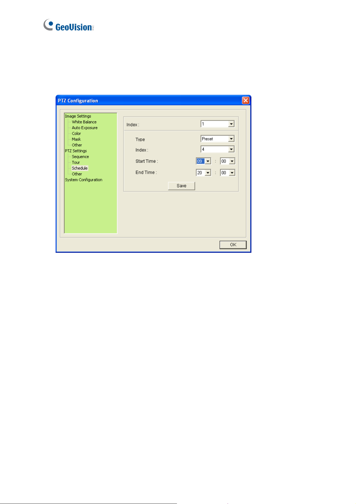
4.11 PTZ Settings- Schedule
You can set up a schedule for the dome to perform Preset, Sequence, Auto Pan, Cruise or
Tour during a specified time. Up to 8 sets of schedule can be configured and saved.
Figure 4-11
1. Select a schedule number from the Index drop-down list.
2. Select a movement type from the Type drop-down list.
3. Select a movement number from the Index drop-down list.
4. Select the Start Time and the End Time using the drop-down lists.
5. To create a new schedule, select a different Index number and repeat Steps 2 to 4.
6. Click Save to save the settings.
60
Page 72

4.12 PTZ Settings– Other
This page contains speed and duration settings of Auto Pan and PT.
4
PTZ Control Panel
Figure 4-12
Auto Pan: An Auto Pan is a pan movement of the dome view between two user-defined
positions. For setup steps, see 4.3 Auto Pan Mode Settings.
Speed: Select the panning speed. The greater value indicates faster speed.
Dwell Time (Left): Select the duration that the dome stays at the left point.
Dwell Time (Right): Select the duration that the dome stays at the right point.
PT Top Speed: The maximum speed for Pan and Tilt movements. Use the drop-down
lists for Pan and Tilt and select a speed (degrees/second).
PT Auto Calibration: Automatically calibrates the camera when it detects any inaccuracy.
This function is disabled by default. For manual calibration, see Self test setting, 4.13
System Configuration.
Set Home Position: First adjust the dome view to a desired position and click this button
to set it as your Home Position.
61
Page 73

4.13 System Configuration
Freeze: Skip showing camera images while traveling from one preset to another. This
function is disabled by default.
Mechanic Flip: The dome view rotates 180° when it is tilted to the maximum angle
(vertically 0° or 90°) and is thus able to track objects continuously.
Start-Up Action: Defines the dome view movement when the camera reboots.
PTZ Idle Protection: When the dome idles for a period of time, the user can select a
movement mode to activate automatic monitoring of the surveillance site. After the idle
time, the selected movement mode will be automatically activated. To configure and
enable this function, follow these steps:
1. Select Idle Protection to start setting.
2. Use the Idle Time (Minute) drop-down list to select the time length allowed for the
dome to remain stationary. The time length can be set from 0 to 120 minutes.
3. Use the drop-down list to select the desired movement mode. The modes include:
Figure 4-13
62
Preset: When the Delay Time is up, the dome will automatically move to the
chosen Preset point. To configure a Preset, see 4.1 Preset Settings.
Sequence: When the Delay Time is up, the dome will automatically perform the
selected Sequence number. To configure a Sequence, see 4.4 PTZ
Settings-Sequence Settings.
Page 74

4
PTZ Control Panel
Auto Pan: When the Delay Time is up, the dome will automatically perform the
selected Auto Pan number. To configure an Auto Pan, see 4.3 Auto Pan Settings.
Cruise: When the Delay Time is up, the dome will automatically perform the
selected Cruise number. To configure a Cruise, see 4.2 Cruise Settings.
Tour: When the Delay Time is up, the dome will automatically perform the
selected Tour number. To configure a Tour, see 4.5 PTZ Settings-Tour Settings.
Load Camera Default (Include PTZ): Click the button to restore default settings to all the
settings in PTZ Configuration dialog box (Figure 4-13).
Load Camera Default (Exclude PTZ): Click the button to restore default settings to
Image Settings and System Configuration in PTZ Configuration dialog box (Figure 4-13).
Self test: Click this button to re-calibrate the GV-IP Speed Dome to maintain its accuracy.
63
Page 75

Chapter 5 Administrator Mode
The Administrator can access and configure the GV-IP Speed Dome over the network. The
configuration categories include: Video and Motion, I/O Control, Events and Alerts,
Monitoring, Recording Schedule, Remote ViewLog, Network, and Management.
64
Figure 5-1
Page 76

Corresponding Section for Configuration Menu
Find the topic of interest by referring to the indicated section.
5.1.1 Video Settings
5.1 Video and Motion
5.1.2 Motion Detection
5.1.3 Text Overlay
5
Administrator Mode
5.2 I/O Control
5.3 Events and Alerts
5.4 Monitoring
5.5 Recording Schedule
5.6 Remote Viewlog
5.7 Network
5.8 Management
5.2.1 Input Settings
5.2.2 Output Settings
5.3.1 Email
5.3.2 FTP
5.3.3 Center V2
5.3.4 VSM
5.3.5 Backup Center
5.3.6 GV-Video Gateway / GV-Recording Server
5.3.7 Viewlog
5.3.8 RTSP
5.5.1 Camera
5.5.2 I/O Monitor
5.7.1 LAN
5.7.2 Advanced TCP/IP
5.7.3 IP Filter
5.7.4 SNMP Settings
5.8.1 Date and Time
5.8.2 Storage Settings
5.8.3 User Account
5.8.4 Log Information
5.8.5 Tools
65
Page 77

5.1 Video & Motion
The GV-IP Speed Dome supports dual streams, Streaming 1 and Streaming 2, which allow
separate codec and resolutions settings for a single video transmission. In a
bandwidth-limited network, such as mobile phone surveillance, this dual-stream feature
allows you to view live video in lower resolution and codec (Streaming 2), and record in
highest resolution 1920 x 1080 and codec H.264 (Streaming 1) at the same time.
Comparison between Stream 1 and Stream 2:
Video Setting Options Stream 1 Stream 2
Video Signal Type
Watermark Setting
Audio In Source
Record Settings
Different codec, resolutions and frame rates can be applied to
Stream 1 and 2.
Not configurable. Settings in
Yes
Stream 1 will be automatically
applied to Stream 2.
66
Page 78

5.1.1 Video Settings
5
Administrator Mode
Figure 5-2 a
67
Page 79

Figure 5-2 b
[Name]
Rename the camera. The camera name will appear on the Live View. To display the camera
name, see 3.9 Camera Name Display.
[Connection Template]
Select the type of your network connection. Unless you select Customized, this option will
automatically bring up the recommended video resolution, frame rate, bandwidth and GOP
size.
[Video Signal Type]
68
Page 80

5
Administrator Mode
Configure the codec type, signal format, resolution and frame rate. Select the codec type
H.264 or MJPEG for the main stream/sub stream. Choose the Flicker Hz value between 60
Hz or 50 Hz. The default is 60 Hz. The supported resolutions are listed blow:
Streams Ratio Supported Resolution
Main Stream
Sub Stream
16:9 1920 x 1080, 1280 x 720, 640 x 360, 488 x 252
16:9 640 x 360, 448 x 252
[Bandwidth Management]
When using the H.264 codec, it is possible to configure the bitrate settings to control
bandwidth usage.
VBR (Variable Bitrate): The quality of the video stream is kept as constant as possible at
the cost of a varying bitrate. The bandwidth is much more efficiently used than a
comparable CBR. Set the image quality to one of the 5 standards: Standard, Fair, Good,
Great and Excellent.
Maximal Bit Rate: When the system bitrate exceeds the specified Maximal Bit Rate, the
system will automatically lower its bitrate so as not to exceed it. Select one of the bitrates
from the drop-down list or select Auto if you do not want to enable this function. By
default, the Maximal Bit Rate is 10 Mbit.
CBR (Constant Bitrate): CBR is used to achieve a specific bitrate by varying the quality
of the stream. The bitrates available for selection depend on the image resolution.
[GOP Structure and Length]
Set the maximum number of seconds between every key frame. The default is 1 (second).
[Record Settings]
Configure recording settings for motion and I/O events, and the condition to record.
Pre-alarm recording time: Activates video recording before an event occurs. Set the
recording time to 1 or 2 seconds. The recording is saved in the buffer of the camera.
Post-alarm recording time: Activates video recording onto the inserted memory card
after an event occurs. Set the recording time from 1 to 30 seconds.
Split-interval: Sets the time length between each event file from 1 to 5 minutes.
Recording Profile: This setting is only applicable for recording to the camera’s memory
card. Select Performance to maximize the lifespan of the memory card by restricting the
69
Page 81

frame rate to 30 fps and maximum bit rate to 4 Mbit. Select Quality to adopt your current
settings. The default setting is Performance..
Record audio: Activates audio recording when an event occurs.
Continue recording to the local storage when live view is accessed: Continues
recording to the memory card when live view is accessed through the Web interface or
other software. This function is enabled by default.
[Text Overlay Settings]
Enable this option to play videos over HTTP protocol or GeoVision software integration.
Overlaid with camera name: Includes camera names on live and recorded videos.
Overlaid with date stamps: Includes date stamps on live and recorded videos.
Overlaid with time stamps: Includes time stamps on live and recorded videos.
Overlaid with digital input description name: Includes the names of selected inputs on
live and recorded videos.
[OSD Settings]
Enable this option to play videos over RTSP protocol, ONVIF protocol or third-party software
integration.
Font Size On-screen display: Set the font size from 1x to 5x to display on the screen.
Overlaid with camera name: Includes camera names on live and recorded videos.
Overlaid with date stamps: Includes date stamps on live and recorded videos.
Overlaid with time stamps: Includes time stamps on live and recorded videos.
[Watermark Setting]
Enable this option to watermark all recordings. The watermark allows you to verify whether
the video has been tampered while it was recorded. See 6.4 Verifying Watermark.
70
Page 82

5
Administrator Mode
5.1.2 Motion Detection
Motion detection is used to generate an alarm whenever movement occurs in the dome view.
You can configure up to 8 detection zones with different sensitivity values. Create at least one
detection zone to enable this function.
Figure 5-3
1. Select a sensitivity value using the slider bar. There are 10 sensitivity levels. The higher
the value, the more sensitive the camera is to motion. The default sensitivity value is 9.
2. Define a detection zone by dragging an area on the image. Click Add when you are
prompted to confirm the setting.
3. To create several areas with different sensitivity values, repeat Steps 1 and 2.
4. Click Save to save the above settings.
5. Click Reset to clear all the selected areas.
71
Page 83

6. For the camera to ignore environmental changes such as rain or snow, select the Ignore
environmental changes.
7. To reduce video noise when the lighting condition changes, select Noise Tolerance.
8. To trigger the alarm output when motion is detected, select the Output 1 and click the
Apply button. To activate the output settings, you must also start Camera monitoring
manually or by schedule. For related settings, see 5.4 Monitoring.
72
Page 84

5
Administrator Mode
5.1.3 Text Overlay
The Text Overlay allows you to overlay any text in any place on the camera view. Up to 16 text
messages can be created on one camera view. The overlaid text will be saved in the
recordings.
Figure 5-4
1. Select the Enable option.
2. Click Set Font to set up the font, font style and font size in a pop-up window.
3. Click any place on the image. This dialog box appears.
Figure 5-5
4. Type the desired text, and click OK. The text is overlaid on the image.
5. Drag the overlaid text to a desired place on the image.
6. Click Set Font to modify the font settings.
7. Click Save to apply the settings, or click Load (Undo) to revert to the last saved setting.
8. Click Preview to see how the text will appear on the image. Click Close to end the
preview.
73
Page 85

5.2 I/O Control
This section introduces how to configure the I/O devices connected to the GV-IP Speed
Dome.
5.2.1 Input Settings
The GV-IP Speed Dome can connect up to 4 input devices.
74
Figure 5-6a
Page 86

5
Administrator Mode
Figure 5-6b
Name: Edit the input name.
Normal State: Set up the input state to trigger actions by selecting Open Circuit (N/O) or
Grounded Circuit (N/C).
Latch Mode: Enable the mode to have a momentary output alarm.
Trigger Digital Output Relay: Select the output to be triggered once the input is
activated.
Record: Enable this function to record when the input is triggered.
Send Video to Center V2: Select the camera to send the images to Center V2 when the
input is triggered.
75
Page 87

Set PTZ camera to Auto Function: Enable this option for your GV-IP Speed Dome to
perform one of the Auto Functions, including Preset, Sequence, Auto Pan, Cruise or
Tour upon input trigger.
Input on: Direct the GV-IP Speed Dome to the specified preset point when the input
is triggered.
Input off: Direct the GV-IP Speed Dome to the specified preset point when the
triggered input is off.
Duration to set preset after input off x seconds: Specify the amount of time the
GV-IP Speed Dome stays in “Input on” preset point before moving to “Input off” preset
point.
Note: The input settings only function after you start Input monitoring manually or by
schedule. To configure the input monitoring, see 5.4 Monitoring.
For related PTZ settings, see Chapter 4 PTZ Control Panel.
76
Page 88

5.2.2 Output Setting
The GV-IP Speed Dome can connect 1 output device.
5
Administrator Mode
Figure 5-7
Select Enable to start the output device. Choose the output signal that mostly suits the device
you are using: N/O (Open Circuit), N/C (Grounded Circuit), N/O Toggle, N/C Toggle, N/O
Pulse and N/C Pulse. For Toggle output type, the output will remain on once it is triggered
until the next trigger. For Pulse output type, the output is triggered for the amount of time you
specify in the Toggle Pulse Mode for x Seconds field.
77
Page 89

5.3 Events & Alerts
For the events of motion detection or I/O trigger, the Administrator can set up two triggered
actions:
1. Send a captured still image by e-mail or FTP.
2. Notify Center Monitoring Stations such as Center V2, VSM or GV-GIS, by video or text
alerts.
To have above triggered actions, you must also set the following features:
• Motion Detection (See 5.1.2 Motion Detection)
• Input Setting (See 5.2.1 Input Settings)
• For e-mail and FTP alerts, it is required to start monitoring (See 5.4 Monitoring).
78
Page 90

5
Administrator Mode
5.3.1 E-mail
After a trigger event, the GV-IP Speed Dome can send an e-mail to a remote user containing a
captured image.
Important: To send e-mail alert upon motion, be sure to set up the detection area on the
Motion Detection page. For details, see 5.1.2 Motion Detection.
Figure 5-8
To enable the e-mail functions:
1. Select Enable to set up e-mail notifications.
2. Server URL/IP Address: Type the SMTP Server’s URL address or IP address.
3. Server Port: Type the SMTP Server’s port number. Or keep the default value 25.
4. From email address: Type the sender’s e-mail address.
5. Send to: Type the e-mail address(s) you want to send alerts to.
6. Alerts interval time in minute: Specify the interval between e-mail alerts. The interval
can be between 0 and 60 minutes. The option is useful for frequent event occurrence.
Any event triggers during the interval period will be ignored.
79
Page 91

7. If the SMTP Server needs authentication, select Need authentication to login and
type a valid Username and Password to log in the SMTP server. If the SMTP Server
needs a secure connection (SSL), select This server requires a secure connection.
8. Email-Alarm Settings: Select to automatically send an e-mail alert when there is a
recording error, when the hard drive is full, when motion is detected, and/or the input is
triggered.
9. Click Apply.
10. In the left menu, select Monitoring and click the Start button to start monitoring.
For related settings to e-mail alerts, see 5.1.2 Motion Detection, 5.2.1 Input Settings and
5.4 Monitoring.
80
Page 92

5
Administrator Mode
5.3.2 FTP
You can also send the captured image to a remote FTP server for alerts.
Important: To send FTP alert upon motions, be sure to set up the detection area on the Moti
Detection page. For details, see 5.1.2 Motion Detection.
Figure 5-9
[Upload to an FTP Server]
1. Select Enable to set up the FTP function.
2. Server URL/IP Address: Type the URL address or IP address of the FTP Server.
3. Server Port: Type the port number of the FTP Server. Or keep the default value 21.
4. Type the Username and Password of the FTP Server.
5. Remote Directory: Type the name of the storage folder on the FTP Server.
81
Page 93

6. Alerts interval time in minute: Specify the interval between FTP alerts. The interval
can be between 0 and 60 minutes. The option is useful for frequent event occurrence.
Any event triggers during the interval period will be ignored.
7. FTP-Alarm Settings: Select to automatically send a snapshot to the FTP Server upon
motion detection or input trigger. Select Continuously send images upon trigger
events (Motion) or Continuously send images upon trigger events (input) to
upload a series of snapshots to the FTP Server upon motion detection or input trigger.
8. Digital Input: Select to send a snapshot to the FTP Server when the input is triggered.
Select Continuously send images upon trigger events (Input).
[Act as FTP Server]
1. Enable FTP access to the GV-IP Cam: The GV-IP Speed Dome acts as an FTP
server, enabling users to download AVI files.
2. Use alternative port: Modify the FTP port if needed or use the default port 21
3. Click Apply.
4. In the left menu, select Monitoring and click the Start button to start monitoring.
To access the internal FTP server through a web browser, enter the IP address or the domain
name of the camera in your browser like this: ftp://192.168.0.10
When you are prompted for Username and Password, enter the default value 123456 in both
fields. Then you should find the AVI files recorded after trigger events.
To change login information of the internal FTP server, see 5.8.4 User Account. For the
related settings to send FTP alerts, see 5.1.2 Motion Detection, 5.2.1 Input / Output Settings
and 5.4 Monitoring.
82
Page 94

5
Administrator Mode
5.3.3 Center V2
After a motion or an I/O triggered event, the central monitoring station Center V2 can be
notified by live videos and text alerts. Up to two Center V2 servers can be connected. For live
monitoring through Center V2, you must already have a subscriber account on each of the
Center V2 server.
Important: To notify the Center V2 Server upon motions, be sure to set up the detection
area on the Motion Detection page.
Figure 5-10
To enable the Center V2 connection:
1. Activate Link: Enable the monitoring through Center V2.
2. Host Name or IP Address: Type the host name or IP address of Center V2.
83
Page 95

3. Port Number: Match the port to Port 2 on Center V2. Or keep the default value 5551. For
details, see 8.1 Center V2.
4. User Name: Type a valid user name to log in to Center V2.
5. Password: Type a valid password to log in to Center V2.
6. Click Apply. The Connection Status should display “Connected” and connected time.
7. To establish connection to the second Center V2, click the Connection 2 tab and repeat
the above steps for setup.
These options you can also find on this Center V2 settings page:
Cease motion detection messages from: Stops notifying Center V2 of motion detection.
Cease input trigger messages from: Stops notifying Center V2 of input trigger from
selected input(s).
Enable schedule mode: Starts the monitoring through Center V2 based on the schedule
you set in the Select Schedule Time section. Refer to 5.5 Recording Schedule for the
same settings.
For related settings to activate the monitoring through Center V2, see 5.1.2 Motion Detection,
5.2.1 Input / Output Setting, and 8.1 Center V2.
84
Page 96

5
Administrator Mode
5.3.4 VSM
After a motion or an I/O triggered event, the central monitoring station VSM can be notified by
text alerts. Up to two VSM servers can be connected. For live monitoring through VSM, you
must already have a subscriber account on each of the VSM server.
Important: To notify the VSM upon motions, be sure to set up the detection area on the Moti
Detection page.
Figure 5-11
To enable the VSM connection:
1. Activate Link: Enable the monitoring through VSM.
2. Host Name or IP Address: Type the host name or IP address of VSM.
85
Page 97

3. Port Number: Match the port to Port 2 on VSM. Or keep the default value 5609. For
details, see 8.2 VSM.
4. User Name: Type a valid user name to log into VSM.
5. Password: Type a valid password to log into VSM.
6. Click Apply. The Connection Status should display “Connected” and connected time.
7. To establish connection to the second VSM, click the Connection 2 tab and repeat the
above steps for setup.
These options you can also find on this VSM setting page:
Cease motion detection messages from: Stops notifying VSM of motion detection.
Cease input trigger messages from: Stops notifying VSM of input trigger from selected
input(s).
Enable schedule mode: Starts the monitoring through VSM based on the schedule you
set in the Select Schedule Time section. Refer to 5.5 Recording Schedule for the same
settings.
For related settings to activate the monitoring through VSM, see 5.1.2 Motion Detection, 5.2.1
Input / Output Settings, and 8.2 VSM.
86
Page 98

5
Administrator Mode
5.3.5 Backup Center
The connection to the GV-Backup Center allows you to back up another copy of recordings
and system log to the GV-Backup Center on an offsite location while the camera is saving
these data to the memory card. The GV-Backup Center provides a PC-based storage and
backup solution. For details on the GV-Backup Center, see GV-Backup Center User’s
Manual.
Figure 5-12
To enable connection to GV-Backup Center:
1. Activate Link: Enable the connection to the GV-Backup Center.
2. Host Name or IP Address: Type the host name or IP address of the GV-Backup Center.
87
Page 99

3. Port Number: Match the communication port on the GV-Backup Center. Or keep the
default value 30000.
4. User Name: Type a valid user name to log into the GV-Backup Center.
5. Password: Type a valid password to log into the GV-Backup Center.
6. Backup Video: Select this option to back up their recordings to the GV-Backup Center.
7. Compact Video: Select this option to only back up their Key Frames to the GV-Backup
Center, instead of full recordings. This option is useful to save the backup time.
8. Resend all files: Select this option to send all the recorded files that have received by the
Backup Center again.
9. Enable Schedule Mode: Enable the GV-Backup Center connection on the schedule you
set in the Select Schedule Time section. Refer to 5.5 Recording Schedule for the same
settings.
10. Click Apply. The Connection Status should display “Connected” and connected time.
If you have a failover GV-Backup Center server which provides uninterrupted backup services in case
the first GV-Backup Center failed, configure the failover GV-Backup Center as below.
1. Automatic Failover Support: Enable the automatic connection to the failover
GV-Backup Center once the connection between camera and the first GV-Backup Center
is interrupted.
2. Host Name or IP Address: Type the host name or IP address of the failover GV-Backup
Center.
3. Port Number: Match the communication port on the failover GV-Backup Center. Or keep
the default value 30000.
4. User Name: Type a valid user name to log into the failover GV-Backup Center.
5. Password: Type a valid password to log into the failover GV-Backup Center.
6. Click Apply.
88
Page 100

5
Administrator Mode
5.3.6 GV-Video Gateway / GV-Recording Server
The GV-IP Speed Dome can be connected with up to two GV-Video Gateway / GV-Recording
Server. To send the video images to the GV-Video Gateway or GV-Recording Server, you
must already have an account on each of the GV-Video Gateway / GV-Recording Server with
the user name and password specified below. Follow the steps below to set up the
connection.
Figure 5-13
To enable connection to GV-Video Gateway / GV-Recording Server:
1. Activate Link: Enable the monitoring through GV-Video Gateway / GV-Recording Server.
2. Host Name or IP Address: Type the host name or IP address of the GV-Video Gateway /
GV-Recording Server.
89
 Loading...