

Page 1
GV-SD200 User's Manual
GV-IP Speed Dome
GV-SD200 User's Manual
Before attempting to connect or operate this product,
please read these instructions carefully and save this manual for future use.
ISD200V104-A
Page 2
© 2013 GeoVision, Inc. All rights reserved.
Under the copyright laws, this manual may not be copied, in whole or in part,
without the written consent of GeoVision.
Every effort has been made to ensure that the information in this manual is
accurate. GeoVision, Inc. makes no expressed or implied warranty of any kind
and assumes no responsibility for errors or omissions. No liability is assumed
for incidental or consequential damages arising from the use of the information
or products contained herein. Features and specifications are subject to
change without notice.
GeoVision, Inc.
9F, No. 246, Sec. 1, Neihu Rd.,
Neihu District, Taipei, Taiwan
Tel: +886-2-8797-8377
Fax: +886-2-8797-8335
http://www.geovision.com.tw
Trademarks used in this manual: GeoVision, the GeoVision logo and GV
series products are trademarks of GeoVision, Inc. Windows and Windows XP
are registered trademarks of Microsoft Corporation.
June 2013
Page 3
Preface
Welcome to the GV-IP Speed Dome User’s Manual.
There are two types of the GV-IP Speed Dome, Indoor and Outdoor. They are distinguished
by model:
Application Model Firmware Version
Indoor GV-SD200
V1.04
Outdoor GV-SD200-S
This Manual provides an overview of the GV-IP Speed Dome and its accessories. The
instructions will guide you through the installation and use of the GV-IP Speed Dome as well.
i
Page 4

Note for Setting Video Signal Format
You can set video signal format of the GV-IP Speed Dome to 30 fps (NTSC) or 25 fps (PAL)
in PTZ > Camera - Misc2 > TV System.
ii
Page 5

Contents
Chapter 1 Overview..............................................................................1
1.1 Features............................................................................................................... 1
1.2 System Requirements.......................................................................................... 2
1.3 Packing List ......................................................................................................... 3
1.4 Optional Accessories ........................................................................................... 5
1.5 Dimensions .......................................................................................................... 9
1.6 Physical Description............................................................................................10
1.7 Connecting the Camera ......................................................................................11
1.7.1 Connecting the Power ...........................................................................11
1.7.2 Connecting the Ethernet Cable..............................................................11
1.7.3 Applying Alarm I/O.................................................................................12
1.7.4 Applying Audio ......................................................................................12
Chapter 2 Installing the GV-IP Speed Dome.....................................13
2.1 Ceiling Mount ......................................................................................................14
2.1.1 Surface Mounting (Indoor Only).............................................................14
2.1.2 Flush Mount (Indoor Only) .....................................................................17
2.1.3 Straight Tube Mount ..............................................................................21
2.2 Wall Mount..........................................................................................................22
2.2.1 Mini Pendent Mount...............................................................................22
2.2.2 Standard Pendent Mount.......................................................................24
2.2.3 Wall Box Mount .....................................................................................25
2.3 Corner Mount......................................................................................................26
2.3.1 Corner Plate Mount ...............................................................................26
2.3.2 Corner Thin Box Mount..........................................................................27
2.4 Pole Mount..........................................................................................................28
2.4.1 Pole Thin Direct Mount ..........................................................................28
2.4.2 Pole Thin Box Mounting.........................................................................29
iii
Page 6

Chapter 3 Accessing the Camera ..................................................... 30
3.1 Installing on a Network........................................................................................30
3.1.1 Checking the Dynamic IP Address.........................................................31
3.1.2 Changing the IP Address.......................................................................32
3.2 Accessing Your Surveillance Images ..................................................................33
3.3 Set Up Video Resolution .....................................................................................34
Chapter 4 Administrator Mode.......................................................... 39
4.1 Home Page.........................................................................................................41
4.1.1 Function Items on Home Page ..............................................................41
4.2 System................................................................................................................45
4.2.1 System ..................................................................................................46
4.2.2 Security .................................................................................................48
4.2.3 Network.................................................................................................54
4.2.4 DDNS ....................................................................................................60
4.2.5 Mail........................................................................................................61
4.2.6 FTP .......................................................................................................62
4.2.7 Application (Alarm Settings)...................................................................63
4.2.8 Motion Detection....................................................................................67
4.2.9 Network Failure Detection .....................................................................71
4.2.10 Storage Management (Local Recording) ...............................................73
4.2.11 Recording (Local Recording) .................................................................75
4.2.12 Schedule ...............................................................................................76
4.2.13 File Location (Snapshots and Web Recording)......................................77
4.2.14 View Log File.........................................................................................78
4.2.15 View User Information ...........................................................................79
4.2.16 View Parameters ...................................................................................80
4.2.17 Factory Default......................................................................................81
4.2.18 Software Version ...................................................................................82
4.2.19 Software Upgrade..................................................................................83
4.2.20 Maintenance..........................................................................................84
4.3 Streaming ...........................................................................................................85
4.3.1 Video Format (Video Resolution / Video Deinterlace)............................85
4.3.2 Video Compression ...............................................................................88
4.3.3 Video OCX Protocol ..............................................................................90
4.3.4 Video Frame Rate .................................................................................91
iv
Page 7

4.3.5
Audio (Audio Mode and Bit Rate Settings).............................................92
4.4 PTZ.....................................................................................................................94
4.4.1 Preset....................................................................................................95
4.4.2 Cruise....................................................................................................96
4.4.3 Auto Pan................................................................................................98
4.4.4 Sequence ............................................................................................100
4.4.5 Tour.....................................................................................................103
4.4.6 Home...................................................................................................105
4.4.7 Tilt Range............................................................................................107
4.4.8 Camera— Exposure ............................................................................108
4.4.9 Camera—WB (White Balance) ............................................................110
4.4.10 Camera—Misc 1 (Miscellaneous Setups Menu 1) ...............................112
4.4.11 Camera—Misc 2 (Miscellaneous Setups Menu 2) ...............................114
4.4.12 Camera- Default..................................................................................116
4.5 Logout...............................................................................................................117
Chapter 5 Advanced Applications .................................................. 118
5.1 Upgrading System Firmware.............................................................................118
5.1.1 Upgrading Firmware Using the Web Interface .....................................119
5.2 Restoring to Factory Default Settings................................................................120
Chapter 6 DVR Configurations........................................................122
6.1 Setting Up IP Cameras .....................................................................................123
6.1.1 Customizing the Basic Settings ...........................................................126
6.1.2 Accessing the PTZ Settings.................................................................127
Chapter 7 Optional Power Box........................................................129
7.1 Power Box Overview.........................................................................................129
7.2 Installation.........................................................................................................131
7.3 Optional Power Box Specifications....................................................................132
Specifications....................................................................................133
Appendix A: Installing DC Viewer................................................................................136
Appendix B: Deleting the Existing DC Viewer..............................................................137
v
Page 8

Appendix C: Setting Up I
Appendix D: RTSP Command.....................................................................................139
nternet Security ....................................................................138
vi
Page 9

1
Overview
Chapter 1 Overview
The Full HD Speed Dome IP Camera transmits digital video and audio data using network
connection. Live video can be monitored and recorded from window-based computer via
network.
The video encoder supports real-time H.264 Full HD resolution. Better image quality and
high resolution are delivered by IP support. It eliminates the “combing” effect due to scene
change and performs more stabilized image.
With IP solution, multiple and authorized users can remotely access the camera from any
location through network using a standard web-browser.
1.1 Features
• 2 M progressive CMOS
• 18x Optical Zoom
• 10x Digital Zoom
• H.264 and MJPEG
• Dual streams
• Full HD Real-time Resolution
• Two-way audio support on Web interface
• Removable IR Cut Filter
• Wide Dynamic Range Pro (WDR Pro)
• Digital Noise Reduction
• Motion Detection
• Schedules for motion detection and alarm functions
• P-Iris Mode for camera exposure
• Ingress protection IP66 (for GV-SD200-S only)
• ONVIF (Profile S) conformant
• 11 languages on Web interface
1
Page 10
1.2 System Requirements
To perform the IP Speed Dome Camera via web browser, ensure your PC is in good network
connection, and meet system requirement as described below.
OS Windows XP / Windows Vista / Windows 7
GV-System GV-System V8.5.4 or later
Browser • Internet Explorer 7.0 or later
• Firefox
• Google Chrome
• Safari
NOTE: With non-IE browsers, only the Play function is available on the live view
window.
2
Page 11
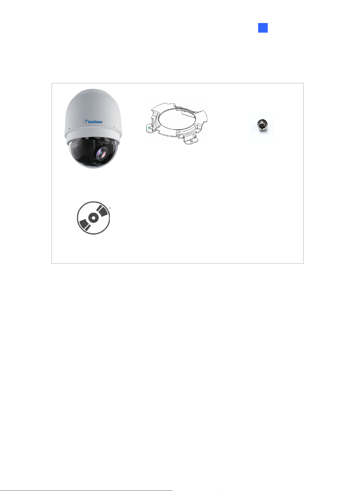
1.3 Packing List
Indoor Dome Camera
1
Overview
Hard Ceiling Mount
Camera Body
GV-IP Speed Dome
Software CD
GV-NVR Software DVD
(GV-MountD603)
M4 Screw (x5)
Plastic Anchor (x5)
Terminal Block
M3 Standard Screw (x1)
3
Page 12
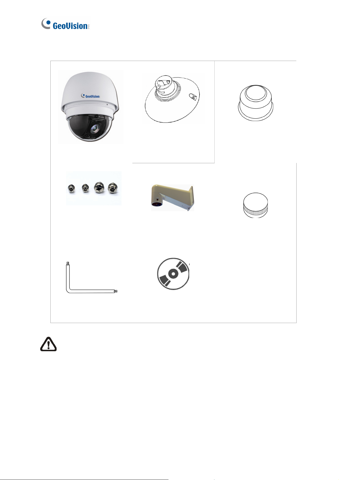
Outdoor Dome Camera
Camera Body
M3 Standard Screw (x1)
M3 Security Screw (x1)
M5 Standard Screw (x1)
M5 Security Screw (x1)
Outdoor Mounting Kit
(GV-MountD902)
Mini Pendent Mount
(GV-MountD202)
Waterproof Rubber
Lubricant
Terminal Block
Security Torx
GV-IP Speed Dome
Software CD
GV-NVR Software DVD
NOTE: If any item is missing or defective, DO NOT install or operate the
product and contact your dealer for assistance.
4
Page 13

1
Overview
1.4 Optional Accessories
Optional accessories can expand the capabilities and versatility of your IP Speed Dome.
Contact your dealer for more information.
Model Number Name Details
GV-MountD100 Straight Tube
(25 cm)
GV-MountD101 Straight Tube
(50 cm)
GV-MountD202
(w/o anti-drop
wire)
Mini Pendent
Mount
Height: 250 mm / 9.8 in
Diameter: 50 mm / 2 in
Weight: 1 kg / 2.2 lb
Supplied with rubber washer-8 x 1, pendent tube
washer x 1, spring washer -8 x 1, waterproof
rubber x 1, M8-12 screw x 1
Height: 500 mm / 19.7 in
Diameter: 50 mm / 2 in
Weight: 1.8 kg / 4 lb
Supplied with rubber washer-8 x 1, pendent tube
washer x 1, spring washer -8 x 1, waterproof
rubber x 1, M8-12 screw x 1
Included in Outdoor packing list.
Dimensions (L x W x D):
184 x 104 x 115.2 mm / 7.24 x 4.09 x 4.54 in
GV-MountD203
(w/o anti-drop
wire)
GV-MountD300
Standard Pendent
Mount
Corner Plate Mount
Weight: 0.6 kg / 1.32 lb
Dimensions (L x W x D):
348 x 104 x 138.6 mm / 13.7 x 4.1 x 5.5 in
Weight: 1.5 kg / 3.3 lb
Supplied with M8-12 screw x 1, spring washer-8 x
1, rubber washer-8 x 1, pendent tube washer x 1,
sponge x 2
Dimensions (L x W x D):
222 x 204 x 117 mm / 8.7 x 8 x 4.6 in
Weight: 2 kg / 4.4 lb
Supplied with washer-8 x 4, spring washer x 4,
M8-16 screw x 4, M8 nut x 4
5
Page 14

GV-MountD301 Corner Thin Box
Mount
GV-MountD302 Wall Box Mount
GV-MountD400 Pole Thin Box
Mount
Dimensions (L x W x D):
300 x 164 x 222 mm / 11.8 x 6.5 x 8.7 in
Weight: 3.05 kg / 6.7 lb
Supplied with washer x 4, M8-16 screw x 4, spring
washer x 4 (Power Box can be set inside the thin
box.)
Dimensions (L x W x D):
270 x 166 x 95 mm / 10.6 x 6.5 x 3.7 in
Weight: 2.2 kg / 4.84 lb
Supplied with M8-16 screw x 4, washer x 4, spring
washer x 4 (Power Box can be set inside the wall
box)
Dimensions (L x W x D):
291 x 136 x 242 mm / 11.5 x 5.4 x 9.5 in
Weight: 3.1 kg / 6.9 lb
GV-MountD401 Pole Thin Direct
Mount
GV-MountD500 Power Box (Input:
110 -115V AC)
Supplied with M8-16 screw x 4, washer x 4, spring
washer x 4, stainless steel straps x 4
(Power Box can be set inside the thin box.)
Dimensions (L x W x D):
232 x 136 x 60 mm / 9.1 x 5.4 x 2.4 in
Diameter: 112~130 mm / 4.4 ~ 5 in
Weight: 0.7 kg / 1.6 lb
Supplied with stainless steel strap x 4, Mx16
screw x 4, washer x 4, spring washer-8 x 4
For outdoor use
Dimensions (L x W): 185.5 x 147 mm / 7.3 x 5.8 in
Weight: 2.6 kg / 5.8 lb
Output: 24VAC 72VA
Weatherproof (IP66)
6
Page 15

1
Overview
GV-MountD501 Power Box (Input:
220 -230V AC)
GV-MountD603 Hard Ceiling Mount
GV-MountD604 T-Bar Ceiling
Mount
For outdoor use
Dimensions (L x W): 185.5 x 147 mm / 7.3 x 5.8 in
Weight: 2.6 kg / 5.8 lb
Output: 24VAC 72VA
Weatherproof (IP66)
Indoor use only (included in packing list)
Height: 19.51 mm / 0.77 in
Diameter: 103.1 mm / 4.05 in
Weight: 0.06 kg / 0.13 lb
Supplied with M4*25 Self Tapping Screws x 5, M4
Anchor x 5, M3*14 Screw x 1, Anti-Drop Spring x 1
Indoor use only
Height: 166.11 mm / 6.5 in
GV-MountD605 5.8" Smoke Cover
GV-MountD901 Indoor Mounting Kit
Diameter: 276 mm / 10.9 in
Weight: 1.34 kg / 2.95 lb
Supplied with M4*8 Screw x 2, Mounting Template
Sticker x 1, sticker x 1
Diameter: 145 mm / 5.7 in
Indoor use only
Height: 75.31 mm / 3 in
Diameter: 110.66 mm / 4.4 in
Weight: 0.26 kg / 0.56 lb
7
Page 16

GV-MountD902 Outdoor Mounting
Kit
E57-A1015-100 Power Adaptor
(Input: 100-115V
AC)
E57-A2015-110 Power Adaptor
(Input: 220-230V
AC)
Outdoor use only (included in packing list)
Height: 73 mm / 2.87 in
Diameter: 142.58 mm / 5.6 in
Weight: 0.26 kg / 0.57 lb
Supplied with Waterproof Rubber, T5 / T10
Hexagon Key, M5 Stainless Screw x 1, M5
Stainless Tamperproof Screw x 1
Indoor use only
Dimensions (L x W): 131 x 90 mm / 5.16 x 3.54 in
Weight: 1.47 kg / 3.23 lb
Output: 24V AC 1.5A
Indoor use only
Dimensions (L x W): 131 x 90 mm / 5.16 x 3.54 in
E57-A2030-110 Power Adaptor
(Input: 220-230V
AC)
E57-A1030-100 Power Adaptor
(Input: 100-115V
AC)
Weight: 1.47 kg / 3.23 lb
Output: 24V AC 1.5A
For outdoor use
Dimensions (L x W): 131 x 90 mm / 5.16 x 3.54 in
Weight: 1.47 kg / 3.23 lb
Output: 24V AC 3A
For outdoor use
Dimensions (L x W): 131 x 90 mm / 5.16 x 3.54 in
Weight: 1.47 kg / 3.23 lb
Output: 24V AC 3A
8
Page 17

1.5 Dimensions
Indoor
1
Overview
Outdoor
9
Page 18

1.6 Physical Description
There are various connectors located on the Dome Camera’s back plate as shown in the
figures below.
Refer to the diagrams and tables accompanied with for use of each switch/connector.
Figure 1-1a: Indoor Figure 1-1b: Outdoor
A RJ-45 Connector
B ALARM I/O
C Power
D Micro SD Card Slot
E Factory Reset Button
F Audio I/O
NOTE: DO NOT change the IP Speed Dome Camera’s Communication Switch
factory default settings.
10
Page 19

1
Overview
1.7 Connecting the Camera
Follow the instructions below to complete IP Speed Dome Camera connection.
1.7.1 Connecting the Power
Refer to the illustrations below to connect power core through the power adaptor. The colors
of the wires vary for different power adaptors.
Pin Definition
1 AC_2
2 GND
3 AC_1
NOTE: If you have purchased GeoVision’s optional power adaptors, connect
the green or green/yellow wire to GND. The two remaining wires are
interchangeable, and both wires can be connected to AC_2 or AC_1.
1.7.2 Connecting the Ethernet Cable
Use of Category 5 Ethernet cable is recommended for network connection; to have best
transmission quality, cable length shall not exceed 100 meters. Connect one end of the
Ethernet cable to the RJ-45 connector of the IP Speed Dome Camera, and the other end of
the cable to the network switch or PC.
NOTE: In some cases, you may need use an Ethernet crossover cable when
connecting the IP Speed Dome Camera directly to the PC.
Check the status of the link indicator and activity indicator LEDs; if the LEDs are unlit, check
LAN connection.
Green Link Light indicates good network connection.
Orange Activity Light flashes for network activity indication.
11
Page 20

1.7.3 Applying Alarm I/O
The IP Speed Dome Camera supports 4 digital alarm inputs and 2 digital alarm outputs.
Make sure the alarm connections are properly wired before starting to configure alarm
related settings on this “Application” page. Refer to the pin definition table below for alarm
system wiring.
Pin Definition Pin Definition
1 ALARM_OUT_NC_1 7 ALARM_OUT_COM_2
2 ALARM_OUT_NO_1 8 GND
3 ALARM_OUT_COM_1 9 ALARM_IN_4
4 GND 10 ALARM_IN_3
5 ALARM_OUT_NC_2 11 ALARM_IN_2
6 ALARM_OUT_NO_2 12 ALARM_IN_1
1.7.4 Applying Audio
Refer to the illustrations below to set up the audio according to the Audio pin definition.
Pin Definition
1 LINE_OUT
2 GND
3 LINE_IN
12
Page 21

Chapter 2 Installing the GV-IP Speed
Dome
With the proper accessories, GV-IP Speed Dome can be installed differently to suit different
environments. The table below lists the installation methods available and the accessories
you need to purchase for each installation methods.
Installation Methods
Indoor Type Outdoor Type
Ceiling Mount
Surface Mount
Flush Mount GV-MountD604
Straight Tube Mount GV-MountD100 / D101
Wall Mount
Mini Pendent Mount GV-MountD202
Standard Pendent
Mount
Wall Box Mount GV-MountD302
Corner Mount
Standard package is enough
GV-MountD603 (Supplied)
GV-MountD603 (Supplied)
GV-MountD901
GV-MountD901
GV-MountD203
GV-MountD901
GV-MountD901
GV-MountD202 / D203
Accessories Required
N/A
N/A
GV-MountD100 / D101
GV-MountD902 (Supplied)
Standard package is enough
GV-MountD202 (supplied)
GV-MountD902 (supplied)
GV-MountD203
GV-MountD902 (supplied)
GV-MountD302
GV-MountD902 (supplied)
GV-MountD202 (supplied) / D203
Corner Plate Mount GV-MountD300
GV-MountD901
GV-MountD202 / D203
Corner Thin Box
Mount
Pole Mount
Pole Thin Direct
Mount
Pole Thin Box Mount GV-MountD400
GV-MountD301
GV-MountD901
GV-MountD202 / D203
GV-MountD401
GV-MountD901
GV-MountD202 / D203
GV-MountD901
GV-MountD202 / D203
GV-MountD300
GV-MountD902 (supplied)
GV-MountD202 (supplied) / D203
GV-MountD301
GV-MountD902 (supplied)
GV-MountD202 (supplied) / D203
GV-MountD401
GV-MountD902 (supplied)
GV-MountD202 (supplied) / D203
GV-MountD400
GV-MountD902 (supplied)
GV-MountD202 (supplied) /D203
Page 22

2.1 Ceiling Mount
There are three kinds of Dome Camera ceiling mounting methods: hard-ceiling, in-ceiling and
mounting with Straight Tube. Refer to the following sections for more details.
2.1.1 Surface Mounting (Indoor Only)
Surface Mount is a standard installation for an indoor Dome Camera, and the mounting
accessories are included in the indoor Dome Camera’s standard packing list.
Surface Mount
GV-MountD603
(Supplied)
Figure 2-1
Follow the steps:
1. Mark the positions of the three screw holes on the Hard Ceiling Mount at the chosen
installation location.
2. In the marked locations, drill each hole slightly smaller than the supplied Screw Anchors,
and put supplied Anchors into these drilled holes.
14
Figure 2-2
Page 23

2
Installing the GV-IP Speed Dome
3. Fasten the Hard Ceiling Mount with the three supplied Self-tapping Screws.
4. Thread the connected cables and wires through the center hole of the Mount and
connect the cable to the camera body.
5. Users can choose to hide the cable and wires inside the ceiling, and put the rubber from
the accessory package to fill the gap at the side of the Fixing Plate. Or let the cables out
from the gap on the side of the Fixing Plate (as shown in the diagram).
Figure 2-3
6. Install the Camera on the fixed Hard Ceiling Mount by turning the Camera clockwise.
Figure 2-4
7. Fasten the screw at the side of the Fixing Plate.
Figure 2-5
15
Page 24

8. After installing the Camera on the Hard Ceiling Mount, put the Dome Cover back, and
use a flat screw drive to fasten two supplied Flat Screws on the Dome Cover.
Figure 2-6
9. Fasten the supplied Standard Screw on the Dome Cover.
Figure 2-7
16
Page 25

2.1.2 Flush Mount (Indoor Only)
Flush Mount
Figure 2-8
2
Installing the GV-IP Speed Dome
GV-MountD604
(Optional Accessory)
Follow the steps:
1. Attach the Hard Ceiling Mount on the T-Bar bottom mount with the three supplied
screws.
Figure 2-9
2. Install the Camera on the fixed Hard Ceiling Mount by turning the Camera clockwise.
Figure 2-10
17
Page 26

3. Tighten the screw at the side of the Fixing Plate.
Figure 2-11
4. Tighten the screw at the side of the Fixing Plate to finish installing the camera on T-Bar
Bottom Mount.
Figure 2-12
5. Place the Ceiling Sticker on the ceiling plate, and cut the circle part out of the ceiling.
Figure 2-13
18
Page 27

2
Installing the GV-IP Speed Dome
6. Loosen the three screws counterclockwise on the In-Ceiling (T-Bar) Mount until the
wings are loose enough to be turned outward from the ring. (as shown in the second
diagram)
Figure 2-14
7. Put the T-Bar Bracket into the ceiling opening and fix the In-Ceiling (T-Bar) Mount on
the ceiling by tightening three screws clockwise.
Figure 2-15
8. As you tighten the screws, the Wings will approach the ceiling board until it is
completely clinched into the board.
Figure 2-16
NOTE: Make sure the Wings of the T-Bar Bracket completely clinched into the
ceiling board.
19
Page 28

9. Put the Power Cable and Ethernet Cable down through the center hole of the T-bar and
connect it to the Camera.
10. Put the installed T-Bar Bottom Mount with Camera into the ceiling opening.
Figure 2-17
11. Tighten the screws to fix T-Bar Bottom Mount on the T-Bar Bracket.
Figure 2-18
12. Fix the Trim Ring to the T-Bar Bracket.
20
Figure 2-19
Page 29

2
Installing the GV-IP Speed Dome
2.1.3 Straight Tube Mount
The Straight Tube is available in different length: 25 cm and 50 cm.
Ceiling Mounting: Straight Tube
GV-MountD100 / GV-MountD101
(Optional Accessory)
GV-MountD901: for indoor GV-SD200, optional accessory
GV-MountD902: for outdoor GV-SD200, supplied
Figure 2-20
Follow the steps:
1. Ensure that the ceiling can support the weight of the Dome Camera and Straight Tube.
2. Make a cable entry hole on the ceiling.
3. Fix the suspension bracket to the ceiling with proper screws and screw anchors.
4. Thread the cables through the Straight Tube and the Mounting kit.
NOTE: After threading the cables, block the cable entry hole with the supplied
sponge(s) to prevent insects from entering the tube.
5. Fix the Mounting Kit to the Straight Tube with the supplied screws and washers.
6. Connect the cables to the Dome Camera.
7. Mount the Dome Camera to the Mounting Kit. (Ensure the Dome Camera is fixed
completely, and the thread holes on the Lock Screw Plate and Mounting Kit are aligned).
Afterwards, screw the supplied M5 standard screw, as shown in the picture.
Figure 2-21
21
Page 30

2.2 Wall Mount
The Dome Camera can be mounted on the wall with Mini Pendent Mount, Standard
Pendent Mount and Wall Box.
2.2.1 Mini Pendent Mount
Wall Mounting: Mini Pendent Mount + Mounting Kit
GV-MountD202
(Supplied for outdoor GV-SD200-S,
optional accessory for indoor GV-SD200)
GV-MountD901: for indoor GV-SD200, optional accessory
GV-MountD902: for outdoor GV-SD200-S, supplied
Figure 2-22
Follow the steps:
1. Make a cable entry hole on the wall to recess the cables. You can also push the Cable
Entry Board on the Mini Pendent Mount’s Mounting Plate to place the cables, as shown
in the photo below.
Mounting
Cable Entry
Figure 2-23
2. Fix the Mini Pendent Mount on the wall with suitable screws and screw anchors of your
choice.
22
Page 31

2
Installing the GV-IP Speed Dome
3. Attach the Waterproof Rubber to the Mini Pendent Mount.
4. Run the cable(s) through the Mini Pendent Mount.
NOTE: Block the cable entry hole with the supplied sponge to prevent insects from
entering the Pendent Mount. The sponge can be placed in two ways as shown in
the illustrations below.
Sponge
Sponge
Figure 2-24
5. Thread the cable(s) through the Mounting Kit and join the Mounting Kit to the Mini
Pendent Mount with the supplied screws and washers. Then adjust the Waterproof
Rubber to the joint.
6. Connect the cable(s) to the Dome Camera.
7. Join the Dome Camera to the Mounting Kit with the supplied screw and washers.
23
Page 32

2.2.2 Standard Pendent Mount
Wall Mounting: Standard Pendent Mount + Mounting Kit
GV-MountD203
(Optional Accessory)
GV-MountD901: for indoor GV-SD200, optional accessory
GV-MountD902: for outdoor GV-SD200, supplied
Figure 2-25
Follow the steps:
1. Make a cable entry hole on the wall to recess the cables. You can also push the cable
entry board on the Standard Pendent Mount’s mounting plate to place the cables (refer
to the illustration in section 4.4.2 Mini Pendent Mount
2. Fix the Standard Pendent Mount on the wall with suitable screws and screw anchors of
your choice.
3. Attach the Waterproof Rubber to the Standard Pendent Mount.
4. Run the cable(s) through the Standard Pendent Mount.
NOTE: Block the cable entry hole with the supplied sponge to prevent insects from
entering the Pendent Mount. Refer to the illustrations in section 4.4.2 Mini Pendent
Mount > Step 4.
5. Thread the cable(s) through the Mounting Kit and join the Mounting Kit to the Standard
Pendent Mount with the supplied screws and washers. Then adjust the Waterproof
> Step 1).
Rubber to the joint.
6. Connect the cable(s) to the Dome Camera.
7. Join the Dome Camera to the Mounting Kit with the supplied screw and washers.
24
Page 33

2
Installing the GV-IP Speed Dome
2.2.3 Wall Box Mount
Wall Box Mounting:
Wall Box Mounting + Standard/Mini Pendent Mount + Mounting Kit
Figure 2-26
Follow the steps.
1. Make a cable entry hole on the wall to recess the cable(s).
2. Fix the Wall Box Mounting on the wall with proper screws and screw anchors. Then run
the cable(s) through the hole on the Wall Box Mounting.
3. Fasten the Standard / Mini Pendent Mount onto the Wall Box Mounting with the supplied
screws and washers. Then thread the cable(s) through the Standard/ Mini Pendent
Mount with the cable(s) coming out of the Pendent Mount’s outlet.
NOTE: Block the cable entry hole with the supplied sponge to prevent insects from
entering the Pendent Mount. Refer to the illustrations in section 4.4.2 Mini Pendent
Mount > Step 4.
4. Attach the Waterproof Rubber to the Standard / Mini Pendent Mount.
5. Thread the cable(s) through the Mounting Kit and join the Mounting Kit to the Standard /
Mini Pendent Mount with the supplied screws and washers. Then adjust the Waterproof
Rubber to the joint.
6. Connect the cable(s) to the Dome Camera.
7. Join the Dome Camera to the Mounting Kit with the supplied screw and washers.
25
Page 34

2.3 Corner Mount
2.3.1 Corner Plate Mount
Corner Wall Mounting:
Corner Standard Mounting Plate + Standard/Mini Pendent Mount + Mounting Kit
Figure 2-27
Follow the steps:
1. Make a cable entry hole on the wall to recess the cable(s).
2. Fix the Corner Mounting Plate on the corner of the wall with suitable screws and screw
anchors. Then run the cable(s) through the hole on the Corner Mounting Plate.
3. Fasten the Standard/ Mini Pendent Mount onto the Corner Mounting Plate with the
supplied screws and washers. Then thread the cable(s) through the Standard/ Mini
Pendent Mount with the cable(s) coming out of the Pendent Mount’s outlet.
NOTE: Block the cable entry hole with the supplied sponge to prevent insects from
entering the Pendent Mount. Refer to the illustrations in section 4.4.2 Mini Pendent
Mount > Step 4.
4. Attach the Waterproof Rubber to the Standard/ Mini Pendent Mount.
5. Thread the cable(s) through the Mounting Kit and join the Mounting Kit to the Standard/
Mini Pendent Mount with the supplied screws and washers. Then adjust the Waterproof
Rubber to the joint.
6. Connect the cable(s) to the Dome Camera.
7. Join the Dome Camera to the Mounting Kit with the supplied screw and washers.
26
Page 35

2
Installing the GV-IP Speed Dome
2.3.2 Corner Thin Box Mount
Corner Box Mounting:
Corner Thin Box + Standard/ Mini Pendent Mount + Mounting Kit
Figure 2-28
Follow the steps:
1. Make a cable entry hole on the wall to recess the cable(s).
2. Fix the Corner Thin Box on the corner of the wall with suitable screws and screw
anchors. Then run the cable(s) through the hole on the Corner Mounting Plate.
3. Fasten the Standard / Mini Pendent Mount onto the Corner Thin Box with the supplied
screws and washers. Then thread the cable(s) through the Standard/ Mini Pendent
Mount with the cable(s) coming out of the Pendent Mount’s outlet.
NOTE: Block the cable entry hole with the supplied sponge to prevent insects
from entering the Pendent Mount. Refer to the illustrations in section 4.4.2 Mini
Pendent Mount
4. Attach the Waterproof Rubber to the Standard / Mini Pendent Mount.
5. Thread the cable(s) through the Mounting Kit and join the Mounting Kit to the Standard/
> Step 4.
Mini Pendent Mount with the supplied screws and washers. Then adjust the Waterproof
Rubber to the joint.
6. Connect the cable(s) to the Dome Camera.
7. Join the Dome Camera to the Mounting Kit with the supplied screw and washers.
27
Page 36

2.4 Pole Mount
2.4.1 Pole Thin Direct Mount
Pole Direct Mounting:
Pole Thin Direct Mounting + Standard / Mini Pendent Mount + Mounting Kit
Figure 2-29
Follow the steps.
1. Fasten the Pole Thin Direct Mounting on a pole with equipped stainless straps.
2. Run the cable(s) through the hole on the Pole Thin Direct Mounting.
3. Fasten the Standard / Mini Pendent Mount onto the Pole Thin Direct Mounting with the
supplied screws and washers. Then thread the cable(s) through the Standard / Mini
Pendent Mount with the cable(s) coming out of the Pendent Mount’s outlet.
NOTE: Block the cable entry hole with the supplied sponge to prevent insects
from entering the Pendent Mount. Refer to the illustrations in section 4.4.2 Mini
Pendent Mount
4. Attach the Waterproof Rubber to the Standard/ Mini Pendent Mount.
5. Thread the cable(s) through the Mounting Kit and join the Mounting Kit to the Standard/
> Step 4.
Mini Pendent Mount with the supplied screws and washers. Then adjust the Waterproof
Rubber to the joint.
6. Connect the cable(s) to the Dome Camera.
7. Join the Dome Camera to the Mounting Kit with the supplied screw and washers.
28
Page 37

2
Installing the GV-IP Speed Dome
2.4.2 Pole Thin Box Mounting
Pole Box Mounting:
Pole Thin Box + Standard/ Mini Pendent Mount + Mounting Kit
GV-MountD400
(Optional Accessory)
GV-MountD202
(Supplied for outdoor,
optional accessory for indoor)
or
GV-MountD203
(Optional Accessory)
GV-MountD901: for indoor GV-SD200, optional accessory
GV-MountD902: for outdoor GV-SD200, supplied
Figure 2-30
Follow the steps:
1. Fasten the Pole Thin Box on a pole with equipped stainless straps.
2. Run the cable(s) through the hole on the Pole Thin Box Mounting.
3. Fasten the Standard/ Mini Pendent Mount onto the Pole Thin Box Mounting with the
supplied screws and washers. Then thread the cable(s) through the Standard / Mini
Pendent Mount with the cable(s) coming out of the Pendent Mount’s outlet.
NOTE: Block the cable entry hole with the supplied sponge to prevent insects from
entering the Pendent Mount. Refer to the illustrations in section 4.4.2 Mini Pendent
Mount > Step 4.
4. Attach the Waterproof Rubber to the Standard/ Mini Pendent Mount.
5. Thread the cable(s) through the Mounting Kit and join the Mounting Kit to the Standard /
Mini Pendent Mount with the supplied screws and washers. Then adjust the Waterproof
Rubber to the joint.
6. Connect the cable(s) to the Dome Camera.
7. Join the Dome Camera to the Mounting Kit with the supplied screw and washers.
29
Page 38

Chapter 3 Accessing the Camera
Once installed, the IP Speed Dome is accessible on a network. Follow these steps to
configure the network settings and access your surveillance images:
3.1 Installing on a Network
These instructions describe the basic connections to install the camera on the network.
1. Using a standard network cable, connect the camera to your network.
2. Connect power using the appropriate power adapter. For details, see 1.7.1 Connecting
the Power.
3. By default, the GV-IP Speed Dome is assigned with an unused IP address by the DHCP
server when the camera is connected to the network. This IP address remains
unchanged unless you unplug or disconnect your camera from the network.
• To see how to look up the IP address assigned by the DHCP server, refer to 3.1.1
Checking the Dynamic IP Address.
• If your router does not support DHCP, the default IP address will be 192.168.0.10. In
this case, it is strongly suggested to modify the IP address to avoid IP address
conflict with other GeoVision IP device on the same LAN. To assign a new static IP
address, see 3.1.2 Changing the IP Address.
NOTE: When accessing the IP Speed Dome for the first time, you must set your
browser to allow a one-time installation of DC Viewer. Refer to Appendix A, Installing
DC Viewer for details.
Page 39

3
Accessing the Camera
3.1.1 Checking the Dynamic IP Address
By default, the GV-IP Speed Dome is assigned with an unused IP address by the DHCP
server when the camera is connected to the network. To look up the dynamic IP address
assigned to the GV-IP Speed Dome and access the Web interface, follow the steps below.
1. Install the GV-IP Device Utility program from the Software CD.
NOTE: The PC installed with GV-IP Device Utility must be under the same LAN with
the camera you wish to configure.
2. On the GV-IP Utility window, click the button to search for the IP Speed Dome. Click
the Name or Mac Address column to sort.
Figure 3-1
3. Find the camera with its Mac Address to see the IP address.
4. To login, type the IP address in your web browser. A dialog box appears.
5. Type the default username and password admin.
6. Click OK to access the Web interface.
31
Page 40

3.1.2 Changing the IP Address
To assign a static IP address or establish a connection to your ISP, log in the Web interface
to access the network setting page.
1. Open your web browser, and type the IP address of the camera or the default IP address
http://192.168.0.10
2. Type the default username and password admin.
3. Click the System tab, select Network in the left menu and select Basic to access the
network settings.
4. To assign a static IP address, select Use fixed IP address and type IP Address, Subnet
if your router does not support DHCP. A dialog box appears.
Figure 3-2
Mask, Router/Gateway, Primary DNS and Secondary DNS.
5. To establish a connection to your ISP, select Use PPPoE and type the username and
password.
6. Click Apply.
IMPORTANT:
• PPPoE should only be enabled if you know which IP address the camera will get
from the ISP. Otherwise, you must use the Dynamic DNS service to obtain a
domain name linked to the camera’s changing IP address first.
For details on Dynamic DNS Server settings, see 4.2.4 DDNS.
• If PPPoE is enabled and you cannot access the unit, you may have to reset it to the
factory default settings and then perform the network settings again.
To restore the factory settings, see 5.2 Restoring to Factory Default Settings.
32
 Loading...